Embed Size (px)
Citation preview
Proposal
for Funding Starting January 2013
Submitted to
Office of Naval Research
(Mr. George Stimak, Dr. Peter Chu)
Electromagnetic Signature Modeling and Measurement of
Multi-Component Ship Power Systems
Professor Osama Mohammed
Florida International University
Energy Systems Research Laboratory
10555 West Flagler Street
Room EC-3983
Miami, FL 33174
Cell Phone: 305-321-5622
AUGUST 2012
2 | P a g e
Abstract
The objective of this research is to create an accurate computational model that computes the
electromagnetic signatures from multi component source such as those found in shipboard power
systems. The electromagnetic fields radiated from electric power components onboard the vessel. These
fields are detected at a distance and announce their presence underwater. If this magnetic signature is
measurable, the source producing it is detectable and could be classified by sensors. Also because of the
increasing sensitivity of magnetic sensors and smart signal processing, signature reduction is very
important. Therefore, it is increasingly important to design and mitigate detection range by complying
with the strict signature requirements. Subsequently, identifying, understanding and modeling the
underlying physical processes of electromagnetic signatures is the subject of this proposal.
We will study a shipboard power system arrangement; develop a comprehensive modeling and
computational evaluation process to identify the voltage and current waveforms that produce these fields.
This will be done for ideal and practical operating conditions, including pulsed load conditions, fault and
other aspects of non-ideal conditions. In addition, other minor objectives are considered. Mitigation as the
second step in signature study is considered and some ideas including proper up-front design of high
power electric propulsion motors, generators for mitigation and optimization of the advanced types of
degaussing and individual component signature mitigation design.
1. Introduction
The efficient control and use of electric energy, electronic components and power electronics devices
are increasingly being used within electrical systems. Examples of such technologies are utilized in many
applications including naval platforms.
The electromagnetic signatures are observable at low frequency in the local fields produced by the
operation of these systems. The improvements in the sensitivity of electromagnetic sensing devices and
smart signal processing enable the identification of these signatures and use it for a variety of reasons.
Therefore, controlling the creation of signatures is vital. Decreasing the detection range may be necessary
at the design stage to achieve proper signature requirements.
Part of our studies and research here aim at predicting the range of the produced signature given the
electromagnetic history of the signature source. This is helpful in assessing the risk of using the
component, either in an operational situation or at the design stage. In military applications, it might be
used in determining the right instant for their control. To this end, identifying, understanding and
modeling the underlying physical processes of EM signatures is proposed.

3 | P a g e
One of the most important aspects of signature studies in power system is the modeling of the
individual components including electrical machines, cable runs and power converters. Since testing
various techniques with realistic component models has substantial computational cost, we need to devise
new and comprehensive modeling techniques that would produce accurate results with manageable
computational time. Many researchers are involved in the modeling of these devices in addition to
defining techniques for the mitigation of radiated fields [1-4]. From the literatures, it is inferred that most
of the works were done in high frequencies due to the effects of increased utilization of electronic devices
that are working at higher frequencies. As discussed above. The low frequency devices also radiate
electromagnetic field that not only disturb other devices in vicinity but also, creates electromagnetic
signature. Therefore, the detection and mitigation of them are important. Reducing the EM field signature
in a naval vessel is necessary. The application of naval technologies to achieve these magnetic silencing
goals will have important military benefits can still be realized even for signature reduction levels lower
than 100%.
The objective of this proposal is to use various techniques in computational electromagnetics to design
proper equivalent source models for components on the vessel where ideal and non-ideal conditions are
considered. This model will make the simulation of low frequency fields in multi-component
environments simpler and faster using numerical techniques for signature studies. In the following
sections, details on the modeling of an example power system with interconnected components (the
vessel's drive power train), for the purpose of evaluating their signatures, are discussed. Another
objective, of this work is the development of a signature-based source recognition that can be considered
as an application of equivalent source modeling. In addition, we will also identify an overview of
mitigation techniques that will aid in their implementation in a shipboard power system.
As a statement of work, it is expected that the research would achieve the following.
Obtaining equivalent models for multi component system including machines, cables, and
converters, electric loads and so on.
Generalize the equivalent source modeling of machines and other components to have the model
for any machine with different sizes, power ratings and operating voltage and current levels.
Identifying and evaluating the power rating and the position of sources by evaluating their
radiated electromagnetic signature at far distance. This will be done using an optimization method
such as genetic algorithms.
Evaluate the electromagnetic interference radiated from components in the near field. This may
have negative effects on the operation of other components producing additional signatures that

4 | P a g e
may add up in the far field. Therefore a new model will be developed to cover the impact on the
signature from the near fields.
In previous research the equivalent source models for electrical machines were designed for
balanced current condition. If the current of a phase of the corresponding generator changes and
unbalanced condition occurs, what would be the impact on the equivalent source model? We
propose to develop a model to deal with this condition
Another situation which occurs frequently in the ship power system is turning components on and
off. We want to consider this condition in our model for the multi component ship power system.
In other words the model will be modified to physical dynamic model.
One of the advantages of equivalent source model can be signature based fault recognition. It is
proposed to design a model and offer related equations for diagnosis or prognosis of fault
conditions by observing the produced signatures for different conditions from a far distance from
the system.
One of the parameters that have impact on the electromagnetic fields at a far distance is vibration.
There is an idea that vibration can be detected from signatures. We will evaluate several
conditions of a single case machine and also multi case machine to determine the effect of
vibration on signatures.
Objectives of mitigation ideas are discussed in section 3.
2. Studying equivalent models
The electromagnetic signature study of electrical machine can be estimated at a far distance based on
the following equations.
2
0 0sin sinsin ( ) sin ( )
4 4
I dl I dlE t r t r
r r
a a
0 sinsin ( )
4
I dlH t r
r
a
However, as mentioned earlier, estimating the radiated field from electrical machines at far distance
requires significant time especially for multi-component studies using physics-based simulations.
Therefore a logical simplification is used here using edge modeling in finite element analysis.
The path and direction of current and the value of current density of the electric machine have a very
important role in establishing magnetic stray fields at far distances whereas magnetic field’s waveform at
far distance is under the influence of direction of the wires in the component windings. Therefore, a line-
5 | P a g e
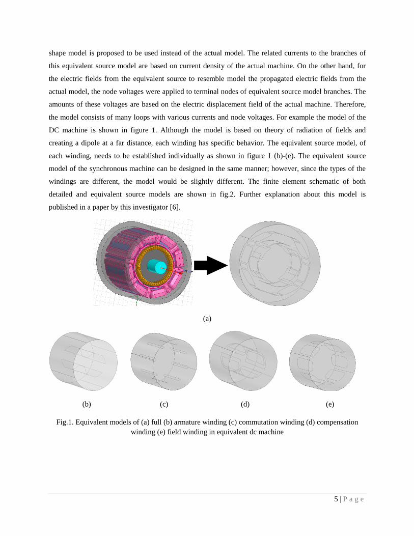
shape model is proposed to be used instead of the actual model. The related currents to the branches of
this equivalent source model are based on current density of the actual machine. On the other hand, for
the electric fields from the equivalent source to resemble model the propagated electric fields from the
actual model, the node voltages were applied to terminal nodes of equivalent source model branches. The
amounts of these voltages are based on the electric displacement field of the actual machine. Therefore,
the model consists of many loops with various currents and node voltages. For example the model of the
DC machine is shown in figure 1. Although the model is based on theory of radiation of fields and
creating a dipole at a far distance, each winding has specific behavior. The equivalent source model, of
each winding, needs to be established individually as shown in figure 1 (b)-(e). The equivalent source
model of the synchronous machine can be designed in the same manner; however, since the types of the
windings are different, the model would be slightly different. The finite element schematic of both
detailed and equivalent source models are shown in fig.2. Further explanation about this model is
published in a paper by this investigator [6].
(a)
(b) (c) (d) (e)
Fig.1. Equivalent models of (a) full (b) armature winding (c) commutation winding (d) compensation
winding (e) field winding in equivalent dc machine

6 | P a g e
(a) (b)
Fig.2. Schematic of the synchronous machine connected to the cable
In the following of section , various aspects of studying equivalent source model are explained.
2.1 Physics based modeling of ship power system and initial results
In a large multi-scale, multi component system, see example of a notional ship power system Fig.3,
several active and passive components exist and they radiate electromagnetic fields.
POWER
CONVERTER &
DRIVES
POWER CABLES
ELECTRICAL
GENERATORS
DC MOTOR
INDUCTIO
N
MOTOR
ELECTRICAL
PULSE LOAD
Fig.3. prototype of multi-component system
Each of these components has radiated electromagnetic fields at a distance. Therefore, it is essential to
consider them in signature study. As mentioned earlier, modeling actual components will increase the
simulation time and in many cases it would not even simulate even in large supercomputers. The Meshed
model of both detailed and equivalent source models of a synchronous generator are shown in Fig.4. The
simulation time of this machine using finite element method while using detailed model takes about
7 | P a g e
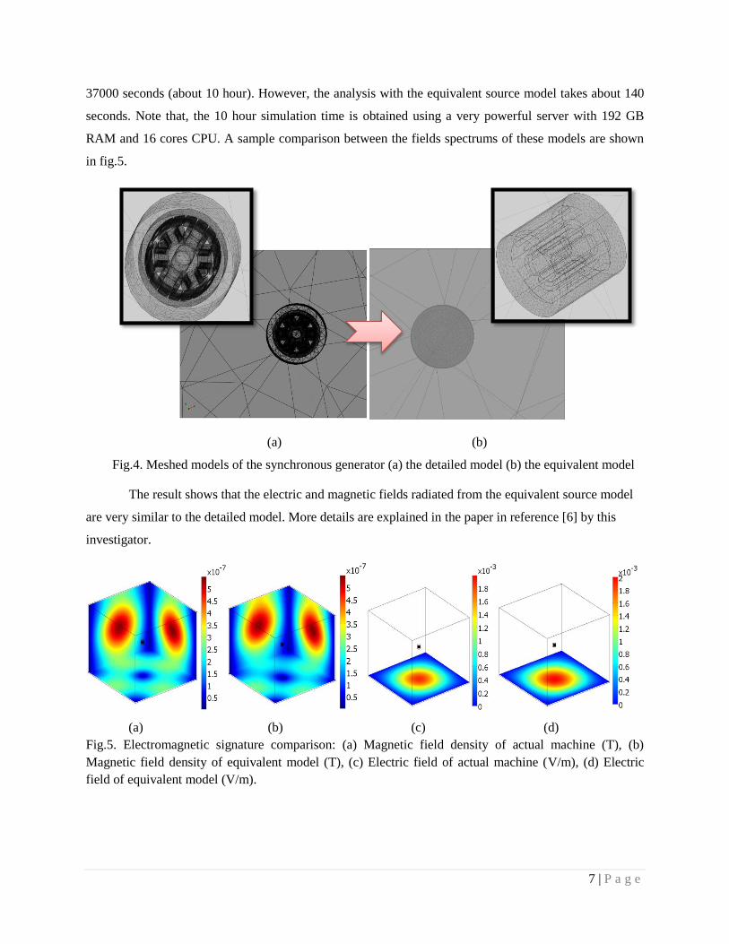
37000 seconds (about 10 hour). However, the analysis with the equivalent source model takes about 140
seconds. Note that, the 10 hour simulation time is obtained using a very powerful server with 192 GB
RAM and 16 cores CPU. A sample comparison between the fields spectrums of these models are shown
in fig.5.
(a) (b)
Fig.4. Meshed models of the synchronous generator (a) the detailed model (b) the equivalent model
The result shows that the electric and magnetic fields radiated from the equivalent source model
are very similar to the detailed model. More details are explained in the paper in reference [6] by this
investigator.
(a) (b) (c) (d)
Fig.5. Electromagnetic signature comparison: (a) Magnetic field density of actual machine (T), (b)
Magnetic field density of equivalent model (T), (c) Electric field of actual machine (V/m), (d) Electric
field of equivalent model (V/m).

8 | P a g e
2.2 Generalized modeling of power system components for various sizes, power, voltage and
current ratings
Basically, the dimensions of the proposed equivalent source model are based on the size of the actual
machine. However, for better and accurate results, an optimization method is used. The proposed
optimization process is Genetic Algorithms-based Particle Swarm Optimization (GA-based PSO). The
PSO is a population-based algorithm that exploits a population of individuals to probe the promising
region of the search space. The details of this specific optimization method are explained in reference [7]
by this investigator.
In this method, the objective functions are the dimensions of the model including their number, and
their geometrical information. In addition to the length of the dimensions and their numbers can be
considered as objectives of the model. The shape of the model can vary from a cone and cube to
polyhedral shapes. A typical schematic of this aspect of the modeling is shown in Fig.6.
Fig.6. Typical Schematic of the equivalent model (optimization aspect)
For other sizes of similar types of machines, an appropriate generalization coefficient can be applied.
This coefficient can be obtained based on the size of the studied machine whereas the coefficient for the
studied machine can be considered as basic values. For other machines, any deviation can be proportional
to this basic values. The factors which are obtained from study of the actual machine can be applied to
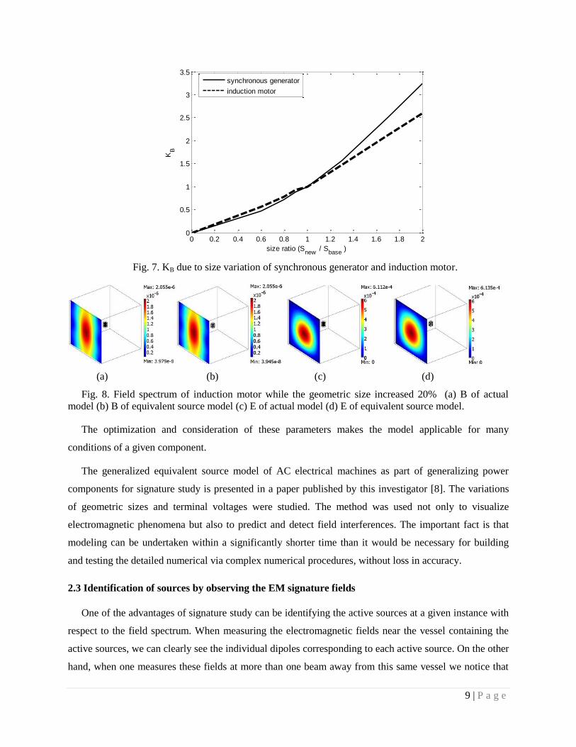
equivalent machine models. This can also be done for different voltage and power ratings. For example,
the curves of the KB factor (to be multiplied by the terminal voltage) due to size variation of synchronous
generator and induction motor is shown in Fig.7. A sample change in the size of an induction machine is
done and the results are shown in fig.8. Note that the size of the equivalent source model in fig.8 is not
modified. This change is applied by multiplying the variation factors [8] by the currents and voltages of
the equivalent source model.
A B
C
9 | P a g e
Fig. 7. KB due to size variation of synchronous generator and induction motor.
(a) (b) (c) (d)
Fig. 8. Field spectrum of induction motor while the geometric size increased 20% (a) B of actual
model (b) B of equivalent source model (c) E of actual model (d) E of equivalent source model.
The optimization and consideration of these parameters makes the model applicable for many
conditions of a given component.
The generalized equivalent source model of AC electrical machines as part of generalizing power
components for signature study is presented in a paper published by this investigator [8]. The variations
of geometric sizes and terminal voltages were studied. The method was used not only to visualize
electromagnetic phenomena but also to predict and detect field interferences. The important fact is that
modeling can be undertaken within a significantly shorter time than it would be necessary for building
and testing the detailed numerical via complex numerical procedures, without loss in accuracy.
2.3 Identification of sources by observing the EM signature fields
One of the advantages of signature study can be identifying the active sources at a given instance with
respect to the field spectrum. When measuring the electromagnetic fields near the vessel containing the
active sources, we can clearly see the individual dipoles corresponding to each active source. On the other
hand, when one measures these fields at more than one beam away from this same vessel we notice that
0 0.2 0.4 0.6 0.8 1 1.2 1.4 1.6 1.8 20
0.5
1
1.5
2
2.5
3
3.5
size ratio (Snew
/ Sbase
)
KB
synchronous generator
induction motor

10 | P a g e
all the individual dipoles become one final dipole. This now increases the complexity of identifying the
active sources with respect to a distant field spectrum. Keeping all this in mind we will develop a
database that stores the electromagnetic spectrum for each of the different axis for each of the possible
configuration of active sources. We will first choose a constant path for all trials. Then start measuring the
electromagnetic fields corresponding to the cases with different sources turned on and off. Once this
database is created we cross reference any incoming field spectrum with our database and it would
provide the closest match. This will also take into account possible failures of the different sources. The
essential part would be to create this database with all the possible scenarios of active sources with
respect to a single path and use a method as genetic algorithm to classify these databases.
2.4 Dynamic modeling (considering turn on and off switch)
One of the scenarios that is frequently encountered in vessels is the turning on and off electrical
machines. By turning on and off machines, the signature field at a far distance will change. Therefore,
similar to other cases, this phenomenon should be considered in the equivalent source model. Hence
appropriate switches are intended to be considered for each machine or component. These switches can be
turned on and off in both offline and also in real-time mode. To do real-time control on switches, the
model can be connected to numerically based software, for instance Matlab. These types of computer
aided software can have access to practical situation by using A/D converters. The command taken from
the real situation will be sent from the software to the model in the physics based modeling program.
2.5 Non ideal and pulsed load conditions (unbalanced current or voltage waveforms)
The equivalent models for electrical machines are designed for balanced current condition. If the
current of a phase of a generator changes and an unbalance occurs, the radiated field will be in different
shape and amplitude. However the radiated field at far distance is dipole, the dipole can have specific
peak bandwidth and amplitude. It is proposed to develop a model to cover this condition. As an initial
work, the current of the component is sent to a lookup table and applied to the equivalent model input
database. So this data can vary and if unbalance in the currents and/or voltages occur, the changes will go
automatically to the database of equivalent model. Then appropriate factors based on the principles of the
equivalent source model will be applied and the model will show the radiated field with unbalanced
currents. This non-ideal condition can be also overvoltage, overcurrent and/s spike due to pulsed load
conditions.

11 | P a g e
2.6 Fault diagnosis and prognosis
Another advantage of equivalent source model can be investigating faults in the system. It is proposed
to design a model and offer related equations to diagnose or even prognoses of faults such as various
types of short-circuits by observing the signatures of different conditions at far distance from the system.
We will propose a new model this condition. In other words, this is similar to the signature-based source
recognition. We need to get the data of healthy and unhealthy conditions and classify them. This can be
done by using search heuristic strategies such as genetic algorithm.
2.7 Detection of vibration by studying the fields
One of the parameters that have an effect on electromagnetic fields at far distance is vibration. There is
an idea that vibration can be detected from radiated fields. By checking several conditions of a single case
machine and also multi case machine, the effect of vibration can be evaluated. Since the effect of
vibration is so slight, high frequency modeling is needed to detect the changes of radiated fields due to
vibration of machines. In the case of vibration, the effective capacitance between machine and
surrounding area will change marginally which can only be detected in high frequency analysis since
capacitive reactance will increase at high frequencies. The deviation of capacitance which has effects on
radiated fields will help in detecting vibration.
2.8. Time Analysis
In addition to frequency and stationary analyses, time analysis is needed in some application. Some
power equipment radiate electromagnetic signature while they are moving. Therefore, time analysis of
these components show their behavior at every instant. For instance, the time analysis of a typical power
system is implemented (see fig.9). First, only the induction machine is considered working in time
analysis and other equipment are stationary.
Fig.9. A typical power setup for the time analysis study

12 | P a g e
(a) (b)
Fig.10. Time analysis of the proposed power setup (fig.9) while only IM is time variant. (a) Magnetic
flux density (T), (b) electric field (V/m).
As shown in fig.10, the changes of the fields are negligible when only the induction machine is
considered time variant. After analyzing the system while only induction motor is time variant, the whole
power setup is considered time variant and the result is shown in fig.11. Considering the whole system
time variations, the field wave-shape is as shown. However, the changes of field amplitude due to time
variation seem to be linear and the wave-shape doesn’t change. In other words, this amplitude variation
can be considered by applying appropriate factors to the voltage and current of the model. By doing this,
implementing time analysis would be done quickly saving significant simulation time.
(a) (b)
Fig.11. Time analysis of the proposed power setup (fig.9) while the whole system is time variant. (a)
Magnetic flux density (T), (b) electric field (V/m).

13 | P a g e
3. Mitigation
One of the factors that are needed to decrease the EM field signature of a naval vessel is the
degaussing system. This system can reduce vessel’s susceptibility to detection. Basically, the magnetic
signatures of a naval vessel are produced by four different sources:
1- Stray field produced by electrical machines like motors, generators, cable and switching
elements.
2- Ferromagnetism induced by the Earth’s natural magnetic field in the hull and other ferrous
material in the vessel.
3- Eddy currents induced in shipboard electrically conducting material while it rotates in the Earth’s
magnetic field.
4- Magnetic field produced by corrosion process.
Actually, each of these sources is important depending on the type and the materials of the naval
vessel. However, in this part of the project, the third and fourth source of magnetic signature assumed to
be negligible.
Initial condition
To reduce magnetic signature, the magnetic field produced by each component should be known
accurately. Therefore, The actual position of each power component as well as their current, power, and
size should be known. Also, the type of cable is very important.
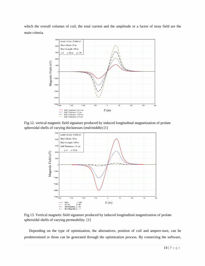
The material of the hull and its thickness has very crucial effects on its signature. Fig.12 and
Fig.13 shows the effect of the permeability and the thickness of the hull on its vertical magnetic field
signature.
3. Intended degaussing system
Degaussing system can mainly be divided to passive and active reduction of ferromagnetic signatures.
The following is the objectives to improve the degaussing system:
3.1 Optimization of the advanced M, L and A type degaussing coil
Advanced M, L and A type degaussing coil are generally used to cancel a vessel’s vertical, athwart
ship and longitudinal field accordingly. The proposal is to implement heuristic optimization method to
find the best configuration instead of using classical least-square method to just adjust the current.
Heuristics optimization methods can be used for combinatorial optimization in which an optimal solution
is sought over a discrete search-space. Optimization of the degaussing system is multi criteria type in
14 | P a g e
which the overall volumes of coil, the total current and the amplitude or a factor of stray field are the
main criteria.
Fig.12. vertical magnetic field signature produced by induced longitudinal magnetization of prolate
spheroidal shells of varying thicknesses (end/middle) [1]
Fig.13. Vertical magnetic field signature produced by induced longitudinal magnetization of prolate
spheroidal shells of varying permeability. [1]
Depending on the type of optimization, the alternatives, position of coil and ampere-turn, can be
predetermined or those can be generated through the optimization process. By connecting the software,

15 | P a g e
MATLAB to COMSOL the process of generating the alternatives and evaluating the overall signature as
well as reaching the goal, best configuration, will be enhanced.
3.2 Novel arrangement of the degaussing coils.
Since the simulation has good accuracy, we can seek for novel arrangement of degaussing coil. The
arrangement is novel in the scene that the shapes and the location of coils are different from the general
M, L and A type degaussing coil. Elliptical, circular and rectangular shape coils can be implemented at
different position to cancel the magnetic field of each electrical machine and also the Earth’s inducing
field on the shipboard equipment and the hull. Also, another solution can be a combination of novel
deployment of the degaussing coils and general M, L and A type.
3.3 Proper up-front design of high power electrical machine.
Proper up-front design of high power electric propulsion motors, generators can decrease the stray
field effectively. In another word, the electromagnetic component can be arranged so that the fields of
each other are canceled while their performances are not affected. Deferent approaches can be examined
in the simulation.
3.4 Optimization of each electrical component
It is possible to measure the stray field produced by each individual machine with accurate simulation.
One of the effective solutions to decrease the overall signature is to design each machines to produce less
stay field. Using different materials and trying to reduce the size of the machine can be one of the possible
solutions. So it is noteworthy to optimize each electrical component to reduce its stray field while its
performance not to be effected.
4. Measurement system for validation
In order to validate all designs and investigation of the proposed equivalent source model with the
entire range of conditions, there is a need to measure radiated fields at far distances. In addition to
validation for some cases such as testing real-time turning on and off machines, experimental test is
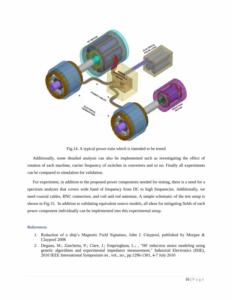
needed. Hence, an experimental arrangement of a complete power system as in fig.14.
Since each power component has its own type of signature, therefore it should be tested individually.
For example, we can get radiated electromagnetic fields of each machine, cables, power supplies, and
drives to know their individual behavior as a source of electromagnetic field. Then, all components can be
collected in a space as power system and the test can be implemented for multi-machine system.
16 | P a g e
POWER
CONVERTER &
DRIVES
POWER CABLES
ELECTRICAL
GENERATORS
DC MOTOR
INDUCTIO
N
MOTOR
ELECTRICAL
PULSE LOAD
Fig.14. A typical power train which is intended to be tested
Additionally, some detailed analysis can also be implemented such as investigating the effect of
rotation of each machine, carrier frequency of switches in converters and so on. Finally all experiments
can be compared to simulation for validation.
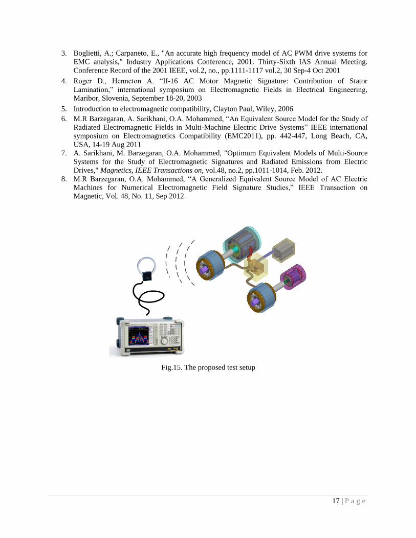
For experiment, in addition to the proposed power components needed for testing, there is a need for a
spectrum analyzer that covers wide band of frequency from DC to high frequencies. Additionally, we
need coaxial cables, BNC connectors, and coil and rod antennas. A simple schematic of the test setup is
shown in Fig.15. In addition to validating equivalent source models, all ideas for mitigating fields of each
power component individually can be implemented into this experimental setup.
References
1. Reduction of a ship’s Magnetic Field Signature, John J. Claypool, published by Morgan &
Claypool 2008
2. Degano, M.; Zanchetta, P.; Clare, J.; Empringham, L.; , "HF induction motor modeling using
genetic algorithms and experimental impedance measurement," Industrial Electronics (ISIE),
2010 IEEE International Symposium on , vol., no., pp.1296-1301, 4-7 July 2010
17 | P a g e
3. Boglietti, A.; Carpaneto, E., "An accurate high frequency model of AC PWM drive systems for
EMC analysis," Industry Applications Conference, 2001. Thirty-Sixth IAS Annual Meeting.
Conference Record of the 2001 IEEE, vol.2, no., pp.1111-1117 vol.2, 30 Sep-4 Oct 2001
4. Roger D., Henneton A. “II-16 AC Motor Magnetic Signature: Contribution of Stator
Lamination,” international symposium on Electromagnetic Fields in Electrical Engineering,
Maribor, Slovenia, September 18-20, 2003
5. Introduction to electromagnetic compatibility, Clayton Paul, Wiley, 2006
6. M.R Barzegaran, A. Sarikhani, O.A. Mohammed, “An Equivalent Source Model for the Study of
Radiated Electromagnetic Fields in Multi-Machine Electric Drive Systems” IEEE international
symposium on Electromagnetics Compatibility (EMC2011), pp. 442-447, Long Beach, CA,
USA, 14-19 Aug 2011
7. A. Sarikhani, M. Barzegaran, O.A. Mohammed, "Optimum Equivalent Models of Multi-Source
Systems for the Study of Electromagnetic Signatures and Radiated Emissions from Electric
Drives," Magnetics, IEEE Transactions on, vol.48, no.2, pp.1011-1014, Feb. 2012.
8. M.R Barzegaran, O.A. Mohammed, “A Generalized Equivalent Source Model of AC Electric
Machines for Numerical Electromagnetic Field Signature Studies,” IEEE Transaction on
Magnetic, Vol. 48, No. 11, Sep 2012.
Fig.15. The proposed test setup