Embed Size (px)
Citation preview

18
Electromagnetic Sensing Techniques for Non-Destructive Diagnosis of Civil
Engineering Structures
Massimo Bavusi et al.* CNR-IMAA,
Italy
1. Introduction
Health Assessment Methods (HAM) and Structural Health Monitoring (SHM) aim to
improve the standard of knowledge regarding the safety and maintenance of structures and
infrastructure acquiring information about geometrical, mechanical and dynamical
characteristics of structures. In earthquake-prone areas, this activity has the double aim of
assessing the buildings structural integrity and extracting information regarding their
response during a seismic event in order to define appropriate activities for risk mitigation.
A number of factors afflict buildings and infrastructure safety in seismic areas:
Outdated codes of practice: a significant number of highly urbanized areas are present
globally, where a high percentage of structures have been designed and erected
considering only gravity loading.
The age of the structures and the real in-situ performance of construction material
significantly affect their overall behaviour.
Structural deficiencies such as poor material qualities and/or degradation of structural
materials (rust, spalling etc.), inadequate construction detailing, low levels of ductility,
brittle collapse mechanisms.
The seismic assessment of structures is performed in terms of the estimation of the
earthquake intensity that would lead to a certain damage condition and/or collapse. The
assessment of the seismic vulnerability of existing buildings is generally based on the
knowledge of building characteristics and through a complex analysis of the possible
collapse mechanisms in order to identify the most probable failure for the given structure
(as example: Ansari, 2005; Douglas, 2007; Moustafa et al., 2010).
The methodological approach for the evaluation of a structure resistance is represented in
Figure 1 where structural knowledge obtained through a series of test assessments is needed
in order to define vulnerability and thus design suitable retrofit strategies.
*Romeo Bernini2, Vincenzo Lapenna1, Antonio Loperte1, Francesco Soldovieri2, Felice Carlo Ponzo3, Antonio Di Cesare3 and Rocco Ditommaso3
1CNR-IMAA, Italy 2CNR-IREA ,Italy 3Basilicata University/DiSGG, Italy
www.intechopen.com

Earthquake-Resistant Structures – Design, Assessment and Rehabilitation
456
Since the level of reliability of the assessment method is related to the adequacy of the model and to the completeness of the information, all useful available data have to be collected in order to define the original structural characteristics such as: geometry of structural elements, characteristics and behaviour of the construction materials, presence of degradation, arrangement of longitudinal and transversal reinforcement. The knowledge of an existing structure is never complete and the level and accuracy of construction details obviously corresponds proportionally with the available original design documentation, the time and funds available for in situ investigations and experimental tests on the structural elements.
Fig. 1. Methodological approach.
A reliable assessment of the vulnerability of buildings is also strictly connected to the
evaluation of the mechanical characteristics of the constitutive materials. This can be
particularly complex for concrete, due to the high variability of its resistance that depends
on intrinsic factors such as the composition as well as the environmental and maturing
conditions, and other factors attributable to the collection technique and reworking of the
concrete sample and the test conditions in general (Barlet, 1994).
A number of tests and methods have been developed for evaluating the resistance of
construction materials ranging from completely non-destructive tests (NDT), where there is
no damage to the structural element, using methods where the concrete surface is only
slightly damaged, to partially destructive or destructive tests (DT), where the structural
element has to be repaired afterwards.
The classical NDT methods, generally used for Reinforced concrete (R/C) structures, are the
surface hardness method coupled with the ultrasonic method. As these methods are
influenced in different and/or opposing ways by some fundamental parameters, their
combined use allows outputs with minimal dispersion to be obtained. It is generally not
advisable to use a single non-destructive test to estimate the strength in situ of concrete.
The range of properties that can be assessed using the range of NDT methods is significant
and includes fundamental parameters such as density, elastic modulus as well as surface
hardness, reinforcement location and depth of cover concrete. In some cases it is also
possible to check the quality of workmanship and structural integrity through the ability to
detect voids, cracking and delamination.
Preliminary tests can be performed with a covermeter according to the procedures described in the British Standard 188:204. With this technique it is possible to determine the presence and size of reinforcing bars, laps, transverse steel and depth and position of reinforcement.
www.intechopen.com

Electromagnetic Sensing Techniques for Non-Destructive Diagnosis of Civil Engineering Structures
457
The identification of the position of the reinforcement bars is also used as a preliminary to the other NDT (such as Ultrasonic Pulse Velocity, Schmidt Rebound Hammer, Pull-out UNI EN 12504-3, 2005) and also the DT (Core Extraction and Compression Test). In addition the partially destructive method of removing the cover concrete in some areas and measuring directly the diameter and type of the reinforcement can be performed. The Schmidt rebound hammer test is principally a surface hardness tester and is carried out
according to UNI EN 12504-2 (2001). The system works on the principle that the rebound of
an elastic mass depends on the hardness of the surface against which the mass impinges.
There is little apparent theoretical relationship between the strength of concrete and the
rebound number of the hammer, however within limits, experimental correlations are
established between strength properties and the rebound number. All of this cannot be
generalized and should be calibrated for each type of existing concrete, for example using
the results of compression tests. In the some cases the results of the hammer tests, taken as a
rebound average (Ir) is used individually to assess the homogeneity of the concrete.
The Ultrasonic test is carried out in compliance with UNI EN 12504-4 (2005) and is aimed at
determining the propagation velocity of a mechanical vibration pulse in concrete. By
measuring the pulse crossing time and the distance between the two probes, the apparent
propagation velocity can be calculated. This value can differ from the real value when the
elastic waves undergo deviations from the path identified by the conjunction line between
the two probes (RILEM 1972). The factors that affect the ultrasonic test the most are linked to
the concrete composition, environmental and test conditions.
When interpreting the NDT results, special attention is needed regarding the presence of
possible anomalies which can negatively influence the experimental assessment of the in
situ concrete mechanical characteristics. Such anomalies are generally characterized through
an evident correlation of the experimental datum with either a physical parameter of
reference (usually compressive strength from DT) or with respect to the trend shown by the
data acquired in the same context of structural homogeneity. These anomalies usually arise
from improper execution of the test or from the fact that the test is carried out in non-ideal
conditions.
Direct measure of the compressive strength of concrete in a structure is provided by the
Concrete Core Extraction and Compression method (DT). The process of obtaining core
specimens and interpreting the strength test results is often affected by various factors that
influence either the in-place strength of the concrete or the measured strength of the test
specimen (UNI EN 12504-1, 2002). In spite of such disturbance factors, values measured in
this way are certainly the most reliable possible. Furthermore errors can be reduced using
the A.C.I. 214.4R-03 guidelines which summarize current practices for obtaining cores and
interpreting core compressive strength test results.
Immediately after extraction, the core concrete is tested for carbonation (also called
depassivation). Carbonation penetrates below the exposed surface of concrete extremely
slowly. The significance of carbonation is that the usual protection of the reinforcing steel
generally present in the concrete due to the alkaline conditions caused by the hydrated
cement paste is neutralized. Thus, if the entirety of the cover concrete is carbonated,
corrosion of the steel will occur if moisture and oxygen can infiltrate the section.
The necessary destruction of the test object usually makes DT methods more expensive, and these testing methods can also be inappropriate in many circumstances. Therefore the use of NDT plays a crucial role in ensuring an economical operation. A general proportion of 1
www.intechopen.com

Earthquake-Resistant Structures – Design, Assessment and Rehabilitation
458
core to 4 non-destructive investigations is recommended. Both the results from the DT and NDT are then combined in order to estimate the in situ concrete strength using the SonReb method. This method is the principal combination of Schmidt Rebound Hammer with Ultrasonic Pulse Velocity used for quality control and strength estimation of in situ concrete (Braga, 1992). Another group of NDT methods are the Dynamic identification tests which can be used in
order to assess fundamental dynamic properties (frequencies and/or modal shapes) of the
structure and indirectly estimate the Young’s modulus of the material (Ponzo et al., 2010).
All dynamic characteristics can be estimated using two different approaches: classical
methodologies based on Fourier analysis (Ditommaso et al., 2010a) or innovative
methodologies based on time-frequency and interferometric analyses (Ditommaso et al.,
2010b; Picozzi et al., 2011). These latter analyses are also useful to detect possible structural
damage occurred after an earthquake (Ditommaso et al., 2011).
The results of the above testing methods (both NDT and DT) are used to calibrate numerical
models. These models can then be compared to the likely seismic loading thus providing the
overall vulnerability of the structure being considered (Ponzo et al. 2011).
Even if the methods described above can ensure (when correctly applied) a high level of
structural knowledge a number of issues remain to be addressed. In order to do this
innovative technologies and new methods must be developed: reduce uncertainty regarding
core extraction points, improve the detection of deflection and deficiencies, detect water
infiltration, improve reinforcement information, improve the depth under investigation, and
reduce time and cost.
Due to rapid and flexible execution, high spatial resolution and deep investigation depth,
electromagnetic sensing techniques are a group of NDT methods which can achieve these
objectives. They can direct the use of classical NDT and DT methods and reduce
uncertainties, coring number and the survey cost. Furthermore, their contribution to the
structural knowledge allows the adoption of lower safety coefficients (through the increase
in available information thus minimising spread) and thus higher calculation resistances.
This in turn reduces the extent and cost of the actions required for the improvement or
seismic retrofit of structures, if needed.
The building and infrastructure diagnostics can be take advantage from the use of new
NDT techniques enabling larger investigation depths, spatial resolution, void and defect
detection capacity, low cost and fastness. Electromagnetic sensing techniques can be an
useful tool in order to achieve these objectives. They are based on injection of a form of
electromagnetic energy (electrical current, radiowave, microwave, light, etc.) into the
surveyed object and gathering of returned signal in order to measure electromagnetic
properties (resistivity, electrical permittivity), reconstruct the inner structure, detect
embedded defects.
In table 1 an overview of the advantages and disadvantages of several techniques (both
classic and innovative) is presented, in terms of cost, speed of procedure, non intrusivity,
accuracy of data obtained and degree of correlation with actual values.
Nevertheless, applying electromagnetic sensing techniques to man made structures, some
adaptation needs to fit stringent requirements in terms of exploration depth, spatial
resolution and signal/noise ratio. In fact, commonly used building materials pose
challenging issues in terms of electrode impedance, coupling antennas, survey modalities,
tomographic reconstruction, sensor size.
www.intechopen.com

Electromagnetic Sensing Techniques for Non-Destructive Diagnosis of Civil Engineering Structures
459
Electromagnetic sensing techniques suitable for civil infrastructures and building diagnostic such as Ground Penetrating Radar (GPR) and Electrical Resistivity Tomography (ERT) are presented in this chapter. Concerning the GPR we focus the attention on the possibility to improve the imaging at low and radio/microwave frequencies by using novel inversion approaches such as the Microwave Tomography (MT). Then, a novel distributed fiber optic sensor technology able to monitor strain and temperature variations, is described. Finally, we discuss about the real contribution provided by electromagnetic sensing techniques in the building and infrastructure monitoring.
Test Method Cost Speed of
procedureDamage effected
Accuracy of data
Degree of correlation
Core samples High Slow Moderate Moderate High
Rebound hammer Very low Fast None Only
surface info
Low
Ultrasonic waves Low Fast None Complete
penetrationModerate
Covermeter Low Fast None Moderate -
Electromagnetic sensing
High Moderate None Good Low/
Moderate
Dynamic Test Low Moderate None Good None/Low
Table 1. Advantages and disadvantages of different health assessment techniques.
2. Electromagnetic sensing techniques
Electromagnetic sensing techniques use is now rather diffuse in several earth science fields such as geology, hydrogeology, seismology, glaciology, stratigraphy of urban areas study, polluted areas study, landslides characterization, etc. Few years ago, non intrusiveness and quickness of these techniques suggested their use for investigating buildings and civil engineering structures. The migration of these techniques towards the engineering can be identified with the Microgeophysics where specific issues are the sensor miniaturizing, signal/noise ratio improvement, exploitation of all available free surfaces for energizing and acquiring signals (Cosentino et al., 2011). Electromagnetic sensing techniques are an useful tool for the diagnostics of civil infrastructures, such as transport ones, in the framework of their static and dynamic behavior before, during and after a crisis event such as an earthquake. In fact, they ensure a fast and not-intrusive diagnosis useful in the pre-event stage since a precautionary diagnosis of strategic buildings and transport infrastructure can be a critical issue in the seismic risk prevention. Moreover, they can represent, during the crisis, a valid tool for the rapid damage mapping
of the civil buildings and infrastructures (bridges, roads, dams, assessment) in order to have
preliminary estimations of those safe for rescue forces. Then, a rapid damage assessment for
private buildings enable a correct estimate of the damaged houses and resources to be
www.intechopen.com

Earthquake-Resistant Structures – Design, Assessment and Rehabilitation
460
committed. Finally, in the post-event stage, restoration interventions can be driven by the
electromagnetic sensing techniques in order to minimize the costs and maximize the results.
The electromagnetic sensing techniques provides information about investigated materials in terms of amplitude and phase of the gathered signals, in turn function of the electromagnetic properties of the materials. Amongst the requirements of the infrastructure diagnostics there is certainly the determination of the structural element thickness, rebar diameters, fractures and defects detection, water content or moisture (as indicators of chemical reactions occurrence), strain. Therefore, the information obtained by the electromagnetic sensing techniques have to be converted in order to provide information directly usable by the engineers. Not all electromagnetic sensing techniques are suitable in becoming NDT techniques. Sensing technique selection have to keep into account a certain degree of electromagnetic noise immunity, high spatial resolution and a suitable sensor size. Other aspects to be kept into account are: - proper survey design; - useful spatial resolution and investigation depth; - suitable electrical contact, electromagnetic and/or mechanical coupling, precise
positioning, boundary problems minimization; - efficient data processing, including image processing and inversion techniques; - easy data interpretation; - possibility of data integration. Ground Penetrating Radar (GPR) and Electrical Resistivity Tomography (ERT) have these
qualities since they are active techniques providing the control on the injected signal, an
adjustable spatial resolution and an useful sensor size. Moreover a number of processing codes
and inversion routines are available allowing well interpretable images, although personnel
with certain degree of experience is required in the data processing and interpretation.
Another class of sensors is the distributed ones, ensuring the availability of measurements
along the entire envelop of the sensor. Among these, Fiber Optic Distributed Sensors based
on Brillouin scattering phenomenon is a promising experimental technique able to provide
field of temperature and strain along the fiber which can be a standard low cost
telecommunication fiber. Unlike other fiber optic sensors, this technique permits the remote
and spatially continuous monitoring of the structure in terms of temperature and strain with
the resolution of some tens of centimetres.
In the following paragraphs we describe those three techniques providing examples of
application and highlighting their strengths and limitations.
2.1 Ground penetrating radar Ground Penetrating Radar is an electromagnetic sensing technique based on the same
operating principles of classical radars (Daniels, 2004). In fact, it works by emitting an
electromagnetic signal (generally modulated pulses or continuous harmonic waves) into the
ground or another natural or manmade object; the electromagnetic wave propagates
through the opaque medium and when it impinges on a non-homogeneity of the
electromagnetic properties, in terms of dielectric permittivity and electrical conductivity, a
backscattered electromagnetic field arises. Such a backscattered field is then collected by the
receiving antenna located at the air/opaque medium interface and undergoes a subsequent
processing and visualization, usually as a 2D image (Figure 2).
www.intechopen.com

Electromagnetic Sensing Techniques for Non-Destructive Diagnosis of Civil Engineering Structures
461
Fig. 2. GPR survey design (upper panel) and radargram (lower panel).
Spatial resolution and investigation depth of GPR method are strictly dependent by the central frequency of the used antenna. In fact, antennas with low and mid frequency (40 MHz - 750 MHz) provided high investigation depth (10 m - 3 m) associated to a relative low spatial resolution (2 m - 10 cm). On the contrary, high central frequency antennas (900 MHz - 2.5 GHz) provide low investigation depths (1 m - 10 cm) and high spatial resolution (5 cm - 0.5 cm). Since the physical size of the antennas decreases as the frequency increases, the requirement of miniaturizing the sensors is naturally achieved for the GPR. As a consequence, the GPR technique is useful for the study of bedrock stratigraphy and cavity detection (Lazzari et al. 2006), groundwater and pollution (Chianese et al. 2006), metal and plastic pipelines such as cables in urban areas, archaeological finds (Bavusi et al. 2009) when low central frequency antennas are used. On the contrary, when high central frequency antennas are used, the GPR, more properly named in this case Surface Penetrating Radar (SPR), can be considered a NDT technique (McCann and Forde 2001) providing precious information about the presence of “embedded” objects such as, reinforced rebars (Shaw et al., 2005; Che et al., 2009), but also embedded “defects” such as voids and, by using special antennas (Huston et al, 2000; Forest and Utsi, 2004; Utsi et al., 2008), fractures. Moreover, the GPR technique can contribute to determine the concrete moisture content (Shaari et al., 2004; Hugenschmidt and Loser, 2008; GPR survey design is a crucial issue since it determines not only the possibility to detect the target (rebar, defect, water infiltration, ecc.), but also the format output in terms or 2D (cross section, time-slice, depth slice) or 3D data volume, kind of processing and difficult of interpretation. A proper GPR survey design have to keep into account: - orientation of searched target; - possibility of exploit one or more suitable free surfaces; - desired spatial resolution and investigation depth; - mispositioning error minimization; - format of the output; - processing and interpretation effort minimization.
www.intechopen.com
Earthquake-Resistant Structures – Design, Assessment and Rehabilitation
462
When rebars are searched, the most used method of acquisition requires a regular orthogonal survey grid with a proper spacing (a few centimeters) in order to have a suitable spatial resolution. Figure 3 shows a the survey design performed in order to check the continuity of longitudinal and transversal rebars and check the degree of success of the concrete restoration intervention based on epoxy resin injection (Bavusi et al., 2010a).
Fig. 3. GPR survey design and results on a beam of a school of L'Aquila damaged by the Abruzzo earthquake of 6th April 2009. a) beam; b) detail of damaged area with gridding; c) regular 4 cm square grid drawn on the beam; d) longitudinal processed radargram n.3.
A radargram has been gathered along each longitudinal and transversal survey line by
using a 1500 MHz antenna provided by survey wheel. This survey design allows to select proper cross-sections and built a data volume. In fact, transversal radargrams offer a view
of longitudinal rebars, while longitudinal radargrams are useful for visualizing transversal rebars. Then, the interpolation of all radargrams allows to built a data volume
and selects more significant time-slices or depth-slices in order to have a plan view of all rebars (Figure 4).
www.intechopen.com

Electromagnetic Sensing Techniques for Non-Destructive Diagnosis of Civil Engineering Structures
463
Fig. 4. a) data volume built by interpolating all radargrams gathered along the survey lines of figure 3c. b) slices extracted at several depths.
Then, GPR method provides very impressive and effective images of the inner of a
reinforced concrete structure. However, the main limitation is that deeper rebar layer is not
well detected due to scattering phenomena and attenuation losses producing in turn a loss
in spatial definition in depth. Moreover the upper layer of rebars produces a strong
disturbance on the rest of radargram.
In order to overcome this drawback, several strategies can be applied:
1. Repeating the measurements on the opposite surface of the structural element, if possible, in order to focus the other rebar layer;
2. Acquiring in cross-polarization mode: this method enables to focus the attention on the concrete matrix and not on the rebars;
3. Applying more robust inversion routines such as the Microwave Tomography. First strategy can be effective, but increases the time consuming. The second one exploits the
property of cross-polarized radargrams which are less sensitive to the rebars normal to the
survey direction and more sensitive to the rebars parallel to the survey direction (Figure 5).
www.intechopen.com

Earthquake-Resistant Structures – Design, Assessment and Rehabilitation
464
Fig. 5. a) Effect of the antenna polarization on the rebar reflection intensity. b) comparison between the normal-polarized and cross-polarized radargram gathered on the longitudinal survey lines n.9 of figure 2c.
Despite of the above mentioned advantages of GPR, one of the obstacles to its use regards the “low interpretability” of the radargram; therefore a an understandable “interpretation and visualization” of the investigated scene entails a high level operator’s expertise and often a-priori information is required. This difficulty of the interpretation is further on affected in the case that no a priori information is available as, for example, it often happens in the case of historical heritage (Masini et al., 2010) where a lack of knowledge about the constructive modalities and materials of the structure can arise. Therefore, a GPR data processing is often necessary to achieve more easily interpretable and reliable reconstructions of the scene, i.e. images that be easily understandable even by a not expert operator. The usual radaristic approaches are based on migration procedures that essentially aim at
reconstructing buried scattering objects from measurements collected above or just at the
air/soil interface. These approaches were first based on graphical methods (Hagendoorn,
1954) based on high frequency assumption of the electromagnetic propagation and
scattering; afterward this approach found a more consistent mathematical background
based on the wave equation of the electromagnetic scattering (Stolt, 1978).
The absence of reflection in the concrete corresponding to the restored fracture indicates the success of the epoxy injection which filled all possible voids. Finally, a retrofit reinforcing intervention can be designed on the bases of the existent rebar arrangement.
www.intechopen.com

Electromagnetic Sensing Techniques for Non-Destructive Diagnosis of Civil Engineering Structures
465
Recently, new data processing based on the inverse scattering problem have been developed and implemented also in realistic situations for infrastructure monitoring (Catapano et al., 2006; Soldovieri and Orlando, 2009, Bavusi et al., 2011). In particular, the microwave tomography approaches have arose as the most suitable ones for the on field exploitation (Soldovieri and Solimene, 2010; Persico et al., 2005). Such a class of approaches is based on the modeling of the electromagnetic scattering phenomena. According to this modelization, the imaging problem is cast as an inverse scattering problem where one attempts to infer the electromagnetic properties of the scattering object starting from the scattered field measured somewhere outside it.
The statement of the problem is then the following: given an incident field, incE , which is
the electromagnetic field existing in the whole space (the background medium) in absence of
the scattering object and is generated by a transmitting antenna, by the interaction of the
incident field with the embedded objects the scattered field SE arises; from the knowledge of
the scattered field SE properties about the scattering targets, either geometrical and/or
structural, have to be retrieved. The mathematical equations subtending the scattering
phenomena to solve the above stated problem are in order.
To this end, we refer to a two-dimensional and scalar geometry. We consider a cylindrical
dielectric object (i.e. invariant along the axis out-coming from the sheet) enclosed within the
domain D illuminated by an incident field linearly polarized along the axis of invariance.
The scattered field is observed over the domain (not necessarily rectilinear). Moreover, we
denote by (r) e by b(r) the permittivity profile of the unknown object and of the
background medium, respectively. In particular, the latter is not necessarily constant (i.e., a
non-homogeneous background medium is allowed too) but has to be known. The magnetic
permeability is assumed equal to that of the free space 0 everywhere. The geometry of the
problem is detailed in Figure 6.
Fig. 6. Geometry of the subsurface prospecting problem
www.intechopen.com

Earthquake-Resistant Structures – Design, Assessment and Rehabilitation
466
The problem, thus, amounts to retrieving the dielectric permittivity profile (r) of the
unknown object(s) from the knowledge of the scattered field SE . The physical phenomenon
is governed by the two equations (Chew, 1995)
2b inc b b b bS S S
D
2S b b b bO S O S O
D
E(r,r ;k ) E (r,r ;k ) k G(r,r';k )E(r',r ;k ) (r')dr' r D
E (r ,r ;k ) k G(r ,r;k )E(r,r ;k ) (r)dr r
(1)
where inc SE E E is the total field, bk is the subsurface (background) wave-number and
b(r) (r) / 1 is the dimensionless contrast function. G( , ) is the pertinent Green’s
function (Leone and Soldovieri, 2003), Or is the observation point and Sr is the position of
the source. In accordance to the volumetric equivalence theorem (Harrington, 1961), the above integral formulation permits to interpret the scattered field as being radiated by secondary sources (the ”polarization currents”) which are just located within the space occupied by the targets.
The reconstruction problem thus consists of inverting the “system of equations (1)” versus
the contrast function. However, since (from the first of the equations 1) the field inside the
buried targets depends on the unknown contrast function, the relationship between the
contrast function and the scattered field is nonlinear. However, the problem can be cast as a
linear one if the first line equation is arrested at the first term of its Neumann expansion.
After doing this incE E is assumed within the targets and the so-called Born linear model
is obtained (Chew, 1995). Accordingly, the scattering model becomes
2S b b b inc bO S O S O
D
E (r ,r ;k ) k G(r ,r;k )E (r,r ;k ) (r)dr r (2)
Let us just remark that, within the linear approximation, the internal field does not depend
on the dielectric profile, which is the same as to say that mutual interactions between
different parts of any object or between different objects are neglected. In other words, this
means to consider each part of the object as an elementary scatterer that does not depend on
the presence of the other scatterers.
Consequently, at this point the problem can be cast as the inversion of the linear integral
equation (2) and the numerical implementation of the solution algorithm requires the
discretization of eq. (2). This task is pursued by resorting to the method of moments (MoM)
(Harrington, 1961).
One of the main feature of a GPR data is its ability to provide images of the inner structure of a
building or infrastructure at all useful observation scales by exploiting antennas with several
central frequencies. Concerning this, the bridge inspection, which is normally carried out by
using classical DT and NDT methods, can derive benefit from the GPR technique (Scott et al.,
2003; Hugenschmidt and Mastrangelo, 2006). Structural particulars of interest are inner rebars,
tendons, boundary conditions, anchors, saddles and other internal elements. On the other
hand, the observation can involve the entire deck of a bridge. Such observations became
crucial when all original project documentations are partially or completely lost.
Figure 7 shows the survey design drown for the deck survey of the deck of Musmeci bridge in Potenza (Basilicata Region, Southern Italy) (Bavusi et al., 2011).
www.intechopen.com

Electromagnetic Sensing Techniques for Non-Destructive Diagnosis of Civil Engineering Structures
467
Fig. 7. a) location of the Musmeci bridge in Potenza, Basilicata Region, Italy. b) location of the survey area respect to the bridge; d) surveyed lane; e) survey grid. From Bavusi M., Soldovieri F, Di Napoli R., Loperte A., Di Cesare A., Ponzo F.C. and Lapenna V (2010).Ground Penetrating Radar and Microwave Tomography 3D applications for the deck evaluation of the Musmeci bridge (Potenza, Italy). J. Geophys. Eng. 8 (2011) 1–14. Courtesy of IOP Publishing Ltd.
A such survey design is able to provide several depth-slices in order to observe the asphalt layer, the sects layer and the lower reinforced concrete plate of the deck. Figure 8 shows more significant depth-slices showing the deck structure at several depths.
Fig. 8. a-d) depth-slices built at 6 cm (a), 20 cm (b), 40 cm (c) and 50 cm (d) by interpolating all radargrams gathered on the survey lines of figure 5e; d-f) depth-slices built at 6 cm (d), 20 cm (e) and 40 cm (f), by interpolating the same radargrams inverted by means of the Microwave Tomography. ab: absorption zone, Gs: Gerber saddle, ps: pillar support, sw: stiffening wall, ls: longitudinal stiffening wall. From Bavusi M., Soldovieri F, Di Napoli R., Loperte A., Di Cesare A., Ponzo F.C. and Lapenna V (2010).Ground Penetrating Radar and Microwave Tomography 3D applications for the deck evaluation of the Musmeci bridge (Potenza, Italy). J. Geophys. Eng. 8 (2011) 1–14. Courtesy of IOP Publishing Ltd.
www.intechopen.com

Earthquake-Resistant Structures – Design, Assessment and Rehabilitation
468
In particular the asphalt layer shows concentrated absorptive zones that can be related to water infiltration zones. In this case the precise positioning of traces is a critical issue since it can produce a staggering effect when rectilinear features are detected. The use of a survey wheel is mandatory such as a certain degree of care in the cart dragging in order to limit mispositioning errors. In this way a residual error can be subsequently reduced by using proper algorithms. Among possible defects afflicting buildings and infrastructures, fractures are a very warring problem. In fact, fractures can be due to several causes: temperature (3 mm), dry up (0.4 mm), load (0.4 mm). They can involve loss of mechanical strength and represent a preferential way for the water infiltration which in turn can favour the developin g of chemical reactions (expanding salt crystallization, oxidation, carbonation, etc.). Crack detection is an important issue in the field of non-destructive testing. Several techniques can be employed in order to check, localize and characterize fractures in manmade buildings: ultrasonic shear waves (De La Haza et al. 2008), elastic waves (Ohtsu et al. 2008), GPR (Utsi et al. 2008). Due to their small size and variable orientation, fractures detection represents a very challenge for the GPR technique. In fact, the crack detection requires the exploitation of all spatial resolution available in the frequency range used. Moreover it requires fracture to be surveyed is filled by air, water or a material different from the host medium in order to produce a backscattered field (Grandjean and Gourry 1996). In addition, the geometry of the fracture with respect to the survey line plays a fundamental role (Tsoflias et al. 2004). For a vertically oriented fracture, a reflection hyperbola arises due to the bottom of the fracture and to each change in the direction of the fracture with respect to the vertical path (Forest and Utsi 2004). By exploiting this property, it is theoretically possible to detect a fracture by using a common GPR dipole antenna, even the use of specifically designed high vertical resolution antennas is very helpful (Forest and Utsi 2004; Utsi et al. 2008). Moreover, data processing plays a fundamental role to improve the ‘imaging’ and the focusing of the buried reflectors (Grandjean and Gourry 1996; Leucci et al. 2007). Figure 9 shows a 1500 MHz GPR survey carried out on a fracture in the floor of the Prefecture of Chania (Crete Island, Greece) (Bavusi et al., 2010b). Fracture zone, located at the middle point of the radargram, is detected by using a classical processing approach, but best performances in terms of spatial resolution can be obtained by using the Microwave Tomography.
2.2 Electrical resistivity tomography Electrical resistivity tomography (ERT) is an electromagnetic sensing technique used to
obtain 2D and 3D images in terms of electrical resistivity of areas of complex geology
(Griffiths and Baker 1993), landslides, watertable, basins, faults.
Technically, during an electrical resistivity measurement, the electric current is injected into
the ground via two 30-40 cm × 1.5 cm steel electrodes and the resulting electrical voltage is
measured between two other electrodes in line with current electrodes (Sharma, 1997). ERT
can be carried out by using different electrode configurations such as dipole-dipole,
Wenner, Schulumberger, pole-dipole, etc. (Figure 10).
At present, such configurations can be carried out by using multi-electrode systems
enabling the automatic switch of all available electrodes previously fixed into the ground.
The system manages the current injection and simultaneous potential measurements which
can occur simultaneously at more potential electrodes in case of multichannel systems.
www.intechopen.com

Electromagnetic Sensing Techniques for Non-Destructive Diagnosis of Civil Engineering Structures
469
Fig. 9. a) GPR survey design carried out at the Prefecture of Chania (Crete, Greece) on a fracture in the floor. Fracture zone is at the middle point of the radargrams. b) processed radargram; c) Microwave Tomography From Bavusi M., Soldovieri F., Piscitelli S., Loperte A., Vallianatos F. and Soupios P. (2010). Ground-penetrating radar and microwave tomography to evaluate the crack and joint geometry in historical buildings: some examples from Chania, Crete, Greece. Near Surface Geophysics, Vol.8, No. 5, pp. 377-387. Courtesy of EAGE Publications BV..
Fig. 10. a) Dipole-dipole array for the acquisition of a measure of electrical resistivity.
www.intechopen.com
Earthquake-Resistant Structures – Design, Assessment and Rehabilitation
470
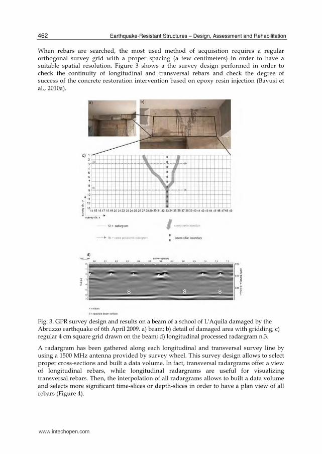
The result of an ERT survey is a distribution 2D or 3D of apparent resistivity where each data point is defined by two coordinates (x and z) depending on the position of the quadrupole (couple of current and potential dipoles) used and a value of apparent resistivity. Then, in order to reconstruct real resistivity distribution, an inversion routine is required. A number of algorithms are available in order to perform this reconstruction such as Res2DInv (Loke and Barker, 1996) for the automatic 2D inversion of apparent resistivity data was used. The inversion routine is based on the smoothness constrained least-squares inversion (Sasaki, 1992) implemented by a quasi-Newton optimization technique. ERT surveys have been successfully applied in geology for stratigraphy and cavity detection (Lazzari et al., 2010), fault characterization (Caputo et al., 2007), landslide studies (Lapenna et al., 2005), in hydrogeology, in environmental problems for contaminant plume detection and waste dump characterization (Bavusi et al., 2006), for hydrogeology and coastal salt water intrusion detection (Satriani et al., 2011a), in agricultural for the root-zone characterization (Al Hagrey, 2007; Satriani et al, 2011b), in archaeology and cultural heritage studies (Bavusi et al., 2009). Figure 11 shows an example of ERT carried out on a piling in an area subjected to landslides. It is well visible the effect of the structure on the water distribution.
Fig. 11. Example of ERT carried out on a piling in an area subjected to landslides.
The ERT exhibits significant potentialities in terms of high resolution and flexibility of the investigation depth that can be varied in a simple way, by varying the electrode spacing. A large electrode spacing provides a high investigation dept and a low spatial resolution. On the contrary, a small electrode spacing allows to achieve a great spatial resolution but a low investigation depth. This characteristic makes the ERT a candidate for the structure and infrastructure
monitoring, even though some problems have to be enfaced. First, a structure or
infrastructure survey requires an electrode spacing ranging between one centimeter and
some decimeter, then sensors have to miniaturized in order to respect the assumption of
geophysics stating transducers have to be punctual (i.e. small respect to dimension of the
investigated volume) and reduce modeling errors (Cosentino et al. 2011; Athanasiou et al.,
2007). Then, a low contact resistance have to be ensured in order to put an adequate current
injection (Cosentino et al. 2011).
www.intechopen.com

Electromagnetic Sensing Techniques for Non-Destructive Diagnosis of Civil Engineering Structures
471
In order to meet these requirements, several devices can be used such as Cu flat-base
electrodes with conductive gel (Athanasiou et al., 2007), Ag/AgCl medical electrodes and
nails (Cosentino et al 2011), Cu-CuSO electrodes (Seppänen et al., 2009). Main limitation of
these devices is the difficulty of put them on a vertical or steeply slope surface, even worse
under a ceiling. Moreover, medical electrodes are not stable in time (Cosentino et al 2011),
while flat-base electrodes are not suitable for the asphalt, where the only possibility to apply
the ERT is making holes in order to put the electrode in the substratum.
In spite of these limitations, the ERT has been successfully applied on masonry, floors, artifacts in order to detect fractures, voids, previous restoration works, structural
particulars, moisture. The application to reinforced concrete is possible in order to detect those targets and rebars, but experiments demonstrates target detection capacity in simple
geometrical configurations (Seppänen et al., 2009; Karhunen et al., 2009). In presence of complex rebar configurations such as reinforcement cages, the potential field
produced by the injected current suffers a warping due to the circuit represented by the cage not easily modelable. A new class of inversion routines is then required in order to solve this
problem. This technique appears still not adequate to be applied to structures and infrastructures, but technological development can provide technical solutions able to
mitigate and overcame described limitations.
2.3 Distributed fiber optic sensors Typically standard NDT systems are based on the use of point sensors, however the
Structural Health Monitoring (SHM) of large civil infrastructures like bridges, dams could require a large number of sensors. For these applications, there is an increasing interest
towards the use of distributed optical fiber sensors. In these sensors is the optical fiber itself that acts as a sensor providing measurements all along the fiber. This approach permits to
monitoring the whole structure by use of a single optical fiber avoiding the need of a huge amount of measurement points and lead to the comprehension of the real static behavior of
the structure rather than a limited number of sensors. Furthermore, distributed sensors could play a fundamental role in civil engineering because no other tools allow the detection
of local phenomena whose location is impossible to be predicted “a priori” like, for instance, for crack detection. Distributed fiber optic sensors are substantially different from other
fiber optic sensors technologies being based on optical scattering mechanism (Raleigh, Raman, Brillouin) occurring during light propagation in common telecom optical fibres.
Spatial resolution is typically achieved by using the optical time domain reflectometry (OTDR) (Barnoski 1976), in which optical pulses are launched into an optical fiber and consequent variations in backscattering intensity is detected as a function of time. Alternative detection techniques such as frequency-domain approaches have been also demonstrated. Raleigh scattering based sensors were first developed, in order to locate fiber breaks or bad splices along a fiber link. However Rayleigh backscatter in standard fibers gives information only about optical attenuation, and it can not be related to other parameters such as temperature or strain. Distributed temperature sensing was first demonstrated by Hartog and Payne (1982), who used temperature-induced variation of the Rayleigh scattering coefficient along the length of liquid-core, but the low reliability of liquid-core fibers may restrict their use. A recent, very interesting approach makes use of the very high spatial resolution allowed by swept-wavelength interferometry, in order to correlate temperature and strain of the fiber with the spectrum of the Rayleigh backscatter spatial fluctuations (Measures 2001). This approach
www.intechopen.com

Earthquake-Resistant Structures – Design, Assessment and Rehabilitation
472
requires standard telecommunication fibers and very high spatial resolution (a few millimeters) has been demonstrated. On the other hand, the main disadvantages are the equipment cost (a tunable laser source is needed for the measurements), and the limited sensing length (70m). Dakin et al. (1985) demonstrated temperature profiles measurement using the variations in the Raman backscattering coefficients of anti-Stokes and Stokes light. The Raman approaches are very practical because conventional silica-based optical fibers can be used as the sensor. The anti-Stokes-Raman-backscattered light is about 30 dB weaker than the Rayleigh-backscattered light. However, its sensitivity to temperature is great. Therefore, systems based on Raman scattering have been commercialized by several manufacturers. Nevertheless, Raman scattering based systems do not allow performing deformation measurements. In 1989, it was reported that the frequency shift of the Stokes-Brillouin-backscattered light (the so-called Brillouin frequency shift) greatly varies with strain and temperature along the fiber (Horiguchi 1989, Culverhouse 1989). Since then, considerable attention has been paid to exploiting Brillouin scattering for distributed sensing. This is for the following reasons. First, strain is a very important parameter in the monitoring of the integrity of civil structures. Secondly, unlike the Raman technique, Brillouin frequency shift measurement does not require calibration of the optical-fiber loss. Furthermore, a very attractive feature of Brillouin-based sensors stems from the use of a standard telecommunications-grade optical fiber as the sensor head. The low-cost and low-loss nature of the sensor make possible to perform distributed measurements over distances of many kilometers. Finally, the tremendous developments in the optical telecommunications market have reduced considerably the cost and increased the performances of optical fibers and their associated optical components. Distributed optical fiber sensors based on stimulated Brillouin scattering (SBS) rely on the
interaction between two lightwaves and an acoustic wave in the optical fiber. The
measurement principle is based on the characteristic that the Brillouin frequency of the
optical fiber is shifted when strain as well as temperature changes occur. Spatial information
along the length of the fiber can be obtained through Brillouin optical time domain analysis
(BOTDA) by measuring propagation times for light pulses travelling in the fiber. This allows
for continuous distributions of the parameter to be monitored.
The research in the beginning of distributed fiber optic strain sensing was mostly based on
laboratory applications (Bernini 2005, Bernini 2008) only in last years in-field demonstration
by a fully distributed sensor have been previously reported (Komatsu 2002).
About bridge structures recently the applications and the validation of distributed strain
sensor during load test has been demonstrated (Matta 2008, Minardo 2011). Other examples
are the installation of a distributed fiber optic strain sensing cable into the inspection gallery
of a dam (Inaudi and Glisic 2005, Glisic and Inaudi, 2007) or the monitoring of extra-long
tunnel, running over 150 km of seafloor geologic body with complicated topographic and
geologic units (Shi, 2003).
However, the use of distributed fiber optic sensors for crack detection in concrete are rare.
This is mainly due to the fact that the instrumentations available for in-field application
have a limited spatial resolution (1m) (Deif 2010). In fact, distributed sensors measure the
with average strain at each measurement point, where the strain is averaged over the length
called spatial resolution. Today, new methods for distributed fiber optic strain sensing with
sub-meter spatial resolution are being developed in order to increase the opportunities in
NDT of civil structures especially for crack detection (Hotate 2002, Zou 2005, Bernini 2007).
www.intechopen.com

Electromagnetic Sensing Techniques for Non-Destructive Diagnosis of Civil Engineering Structures
473
As an example, we report the results obtained in a load test on a road-bridge (Minardo
2011). In particular, the tests were performed by an stimulate Brilouin Scattering portable
sensor prototype with 3m-spatial resolution. The fiber employed for the measurements
was a PVC-coated, single-mode, standard telecom optical fiber. The fiber was bonded
along the lower flange of a 44-m-long, double-T steel beam, by use of a epoxy adhesive.
Strain measurements were performed while loading the bridge with an increasing weight
by use of gravel-loaded trucks (Figure 12a). During the loading test, data were also
collected by other instruments for a cross-correlation. In particular, two vibrating wire
(VW) strain gauges were previously spot-welded to the surface of the steel beam, so as to
provide the strain at the quarter and the middle section of the loaded beam. Figure 10b
depicts the results of the optical fiber measurements, for different load conditions. In
particular, the solid lines refer to the bridge loaded by two, four, and five gravel trucks,
respectively. Each truck had a weight of approximately 47 tons. The same figure also
reports the results of a finite-element-method (FEM)-based numerical analysis (circles).
Numerical data were obtained by modelling each gravel truck as three concentrated loads
applied in correspondence of the three truck axles. A good agreement exists between the
experimental and numerical data. The standard deviation was always less than 20 μ, corresponding to the nominal accuracy of the instrument. Moreover, the maximum strain
provided by the optical fiber sensor ( 350 μ), is in good agreement with the value
provided by the strain gauge placed at the middle beam section (330 μ). Another
interesting feature is that the optical fiber sensor was able to reveal the right-shift of the
center of gravity (CG), when loading the beam with five trucks. Actually, the fifth truck
was not disposed symmetrically with respect to the middle of the bridge; rather it was
closer to the right side. As a consequence, the section at which maximum strain occurs is
shifted to the right in the final load test. Finally, in figure 12b are also reported, for
comparison, the data obtained by the strain gauges (squares). As can be observed a good
agreement between the two different observations is achieved.
Fig. 12. a) bridge used for the load test. b) Distributed strain measurement along the girder,
for different load conditions (solid lines). FEM simulations (open circles). VW strain gauges
(squares).
www.intechopen.com
Earthquake-Resistant Structures – Design, Assessment and Rehabilitation
474
3. Conclusion
Health monitoring of civil engineering structures is devoted to assess the structural integrity
and dynamic behaviour during a seismic event in order to define appropriate activities for
risk mitigation. This need is more stringent for aged infrastructures built following outdated
codes of practice and where the chemical degradation of concrete and irons acted for more
time.
The design of suitable retrofit strategies requires a series of test assessments in order to
define the vulnerability. A number of destructive (DT) and non destructive tests (NTD) and
methods has been developed and applied around the world in order to achieve all necessary
information about construction material. An appropriate survey have to include a suitable
proportion of DT and NDT methods in order to reduce possible damage to investigated
structure, achieve a balanced combination of punctual and distributed information and
reduce the global cost of the survey.
Then, the requirement of new non invasive technique is a stringent need that can be
satisfied by the electromagnetic sensing techniques, this class of geophysical techniques
which can be easily adapted to the specific requirements of civil infrastructures. This is
the case of the Ground Penetrating Radar which at high frequencies provides the needed
spatial resolution and a convenient small size of the antenna. Moreover, this technique
can benefit on a new kind of processing based on the Microwave Tomography (MT)
inversion. In this way the technique can focus small defects such as fractures and voids,
detect rebars with great precision even if deep. The combination of GPR and MT will
provide in future a new class of devices able to supply a not focused image ready for use
by non expert users.
The Electrical Resistivity Tomography can be another suitable technique useful to depict
embedded structural particulars and defects, but its systematic application requires to
solve two problems. First is the design of appropriate non intrusive electrodes, stable in
time and easy to install in any position. A solution can be provided by medical industries
that have experience in the design of electrodes for human body applications. The latter
is the lack of inversion routines able to model the effect of a rebar cage on the potential
field and properly reconstruct the inner of a reinforced concrete structure. Anyway the
ERT is successfully applied on floors, pavements, masonry and reinforced concrete
structures having a simple inner arrangement. Moreover, the industry will provide in
future new sensors, equipments and inversion routines able to mitigate or solve
described problems.
Another class of sensors which will change the way of monitor a civil infrastructure is the
distributed fiber optic sensor able to provide temperature and strain information along
the fiber. This sensor is based on standard telecom fiber optic which is inexpensive and
allows to design sensor sized on the infrastructure to be surveyed or on a particular. It
allows to achieve in real time information by several points of a distributed civil
infrastructure such as a railway, aqueduct, gas or oil pipeline without using transmission
devices. In future optic fibers will be embedded in construction materials allowing a for
life monitoring of an infrastructure. Moreover, a possible technological improvement of
this technique can allow in future its application to the ambient vibration monitoring
(Wenzel and Pichler, 2005).
www.intechopen.com

Electromagnetic Sensing Techniques for Non-Destructive Diagnosis of Civil Engineering Structures
475
4. Acknowledgment
The research leading to these results concerning the Musmeci bridge has received funding from the European Community's Seventh Framework Programme (FP7/2007-2013) under Grant Agreement n° 225663 Joint Call FP7-ICT-SEC-2007-1. Moreover, the authors would like to thank the “Soprintendenza per i Beni Architettonici e Paesaggistici della Basilicata” and the “Direzione Regionale per i beni Culturali e Paesaggistici della Basilicata” that have partially funded the activities. Finally, the authors would like to thank the owner of the Musmeci Bridge, ASI Consortium, for their interest to these research activities and the Municipality of Potenza for the granted authorization to access and work on the structure. Furthermore, the authors would like to thank EAGE Publications BV and IOP Publishing Ltd for copyright permissions granted. Finally, the authors would like to thank TeRN Consortium for supporting this work.
5. References
A.C.I. 214.4R (2003). Guide for Obtaining Cores and Interpreting Compressive Strength
Results.
Al Hagrey, S.A., (2007). Geophysical imaging of root-zone, trunk, and moisture
heterogeneity, J. Exp. Bot., Vol. 58, pp. 839–854.
Ansari F.(2005). Sensing issues in civil structural health monitoring. Spinger.
Athanasiou E.N. , Tsourlos P.I., Vargemezis G.N., Papazachos C.B. and
Barlet, F.M. & MacGregor, J. (1994). Effect of Core Diameter on Concrete Core Strengths.
ACI Materials Journal, Vol. 91, No. 5, September-October.
Barnoski J. K., Jensen S. M., (1976). Fiber waveguides: A novel technique for investigation
attenuation characteristics. Appl. Opt., Vol. 15, pp. 2112 - 2115.
Bavusi M., Rizzo E., Lapenna V. (2006). Electromagnetic methods to characterize the Savoia
di Lucania waste dump (Southern Italy). Environmental Geology, Vol. 51, No. 2, pp.
301-308. DOI 10.1007/s00254-006-0327-9
Bavusi M., Rizzo E., Giocoli A., Lapenna V., (2009). Geophysical characterisation of
Carlo's V Castle (Crotone, Italy). Journal of Applied Geophysics, Vol. 67, No. 4, ,pp.
386-401.
Bavusi, M., Loperte, A.; Lapenna, V., Soldovieri, F., (2010a). Rebars and defects detection
by a GPR survey at a L'Aquila school damaged by the earthquake of April 2009.,
2010 13th International Conference on Ground Penetrating Radar (GPR), 21-25 June
2010.
Bavusi M., Soldovieri F., Piscitelli S., Loperte A., Vallianatos F.and Soupios P. (2010b).
Ground-penetrating radar and microwave tomography to evaluate the crack and
joint geometry in historical buildings: some examples from Chania, Crete, Greece.
Near Surface Geophysics, Vol.8, No. 5, pp. 377-387.
Bavusi M., Soldovieri F., Di Napoli R., Loperte A., Di Cesare A., Ponzo F. C. and Lapenna V.
(2011). Ground Penetrating Radar and Microwave Tomography 3D applications for
the deck evaluation of the Musmeci bridge (Potenza, Italy). Journal of Goph. and Eng,
No. 8, pp. 1–14.
www.intechopen.com

Earthquake-Resistant Structures – Design, Assessment and Rehabilitation
476
Bernini R., Fraldi M., Minardo A., Minutolo V., Carannante F., Nunziante L, Zeni L. (2005).
Damage detection in bending beams through Brillouin distributed optic-fibre
sensor. Bridge Struct. Vol. 1, 355–363.
Bernini R., Minardo A., Zeni L., (2007). Accurate high-resolution fiber-optic distributed
strain measurements for structural health monitoring. Sensors and Actuators A, Vol.
134, pp. 389-395.
Bernini R., Minardo A., Zeni L. (2008). Vectorial dislocation monitoring of pipelines by
use of Brillouin-based fiber-optics sensors. Smart Mater. Struct., Vol. 17, pp.
015006,
Braga, F., Dolce, M., Masi, A., Nigro, D. (1992). Valutazione delle caratteristiche meccaniche
dei calcestruzzi di bassa resistenza mediante prove non distruttive. L’Industria
Italiana del Cemento, Vol. 3, pp. 201-208.
Caputo R., Salviulo L., Piscitelli S., Loperte A., (2007). Late Quaternary activity along the
Scorciabuoi Fault (Southern Italy) as inferred from electrical resistivity
tomographies. Annals of Geophysics, Vol. 50, No., 2, pp.213-224.
Catapano I., Crocco L., Persico R., Pieraccini M., Soldovieri F. (2006). Linear and Nonlinear
Microwave Tomography Approaches for Subsurface Prospecting: Validation on
Real Data. Antennas and Wireless Propagation Letters, Vol. 5, pp. 49-53.
Che W. C., Chen H. L. and Hung S. L. (2009). Measurement radius of reinforcing steel
bar in concrete using digital image GPR. Constr. Build. Mater., Vol. 23, pp. 1057–
1063.
Chew C. W.(1995). Waves and Fields in inhomogeneous media. Piscataway,NJ: IEEE Press.
Chianese D., D’Emilio M., Bavusi M., Lapenna V., Macchiato M. (2006). Magnetic and
ground probing radar measurements for soil pollution mappingin the industrial
area of Val Basento (Basilicata Region, Southern Italy): a case study. Environ Geol ,
Vol. 49, pp. 389–404.
Cosentino P.L., , Capizzi P., Martorana R., Messina P. and Schiavone S. (2011). From
Geophysics to Microgeophysics for Engineering and Cultural Heritage.
International journal of Geophysics, Vol. 2011, pp. 1-8. DOI:
10.1155/2011/428412.
Culverhouse D., Fahari F., Pannell C. N., Jackson D. A.(1989). Potential of stimulated
Brillouin scattering as sensing mechanism for distributed temperature sensors.
Electron. Lett., Vol. 25, No. 14, pp. 913-915.
Dakin J. P., Pratt D.J, Bibby G. W., Ross J. N., (1985), Distributed optical fiber Raman
temperature sensor using a semiconductor light source and detector, Electron. Lett.,
Vol. 21, No. 13, pp. 569-570.
Daniels D.J. (2006). Ground Penetrating Radar. 2nd edition. Institution of Engineering and
Technology, pp.634. DOI: 978-0-86341-360-5; electronic DOI: 978-1-59124-893-4
De La Haza A.O., Petersen C. G. and Samokrutov A. (2008). Three dimesional imaging of
concrete structures using ultrasonic shear waves. Structural Faults & Repair-2008,
12th International Conference, Edinburgh, UK: 10th -12th June 2008.
Deif A., Martın-Perez B., Cousin B., Zhang C., Bao X., Li W. (2010). Detection of cracks in a
reinforced concrete beam using distributed Brillouin fibre sensors. Smart Mater.
Struct., Vol. 19, 055014.
www.intechopen.com

Electromagnetic Sensing Techniques for Non-Destructive Diagnosis of Civil Engineering Structures
477
Ditommaso R., Parolai S., Mucciarelli M., Eggert S., Sobiesiak M. and Zschau J. (2010a).
Monitoring the response and the back-radiated energy of a building subjected to
ambient vibration and impulsive action: the Falkenhof Tower (Potsdam,
Germany). Bulletin of Earthquake Engineering. Vol..8, No. 3. DOI: 10.1007/s10518-
009-9151-4.
Ditommaso R., Mucciarelli M., Ponzo F. C. (2010b). S-Transform based filter applied to the
analysis of non-linear dynamic behaviour of soil and buildings. 14th European
Conference on Earthquake Engineering. Ohrid, Republic of Macedonia, August 30 –
September 03.
Ditommaso R, Mucciarelli M., Ponzo F. C. (2011). Analysis of non-stationary structural
systems by using a band-variable filter. Submitted to Bulletin of Earthquake
Engineering.
Douglas A. (2007). Health Monitoring of Structural Materials and Components: Methods
with Applications. Copyright © 2007 John Wiley & Sons, Ltd.
Forest R. and Utsi V. (2004). Non destructive crack depth measurements with ground
penetrating radar. 10th Int. Conf. on Ground Penetrating Radar,Delft, The
Netherlands, 21–24 June 2004.
Glisic B. and Inaudi D. (2007). Fibre Optic Methods for Structural Health Monitoring. John
Wiley & Sons. ISBN: 0470061421.
Grandjean C. and Gourry J.C. (1996). GPR data processing for 3D fracture mapping in a
marble quarry (Thassos, Greece). Journal of Applied Geophysics,Vol. 36, pp.19-30.
Griffiths, D.H. and R.D. Baker (1993): Two-dimensional resistivity imaging and modelling in
areas of complex geology. J. Appl. Geophys., Vol. 29, pp. 211-226.
Hagedoorn, J. G. (1954). A Process of Seismic Reflection Interpretation. Geophys. Prospect.
Vol. 2, pp 85-127.
Harrington, R.F. (1961). Time-Harmonic Electromagnetic Fields, Mc Graw Hill.
Hartog A. H., and D. N. Payne (1982). Remote measurement of temperature distribution
using an optical fiber. Proc. ECOC ’82, Cannes, France, pp. 215-220, 1982.
Horiguchi T, Kurashima T., Tateda M., (1989). Tensile strain dependence of Brillouin
frequency shift in silica optical fibers. IEEE Photonics Tech. Lett., Vol. 1, No. 5, pp.
107-108.
Hotate K., Tanaka M., (2002). Distributed fiber Brillouin strain sensing with 1-cm spatial
resolution by correlation-based continuous-wave technique. IEEE Phot. Technol. Let.
Vol. 14, 179-181.
Hugenschmidt J. and Mastrangelo R. (2006). GPR inspection of concrete bridges Cem. Concr.
Compos., Vol. 28, pp. 384–92.
Hugenschmidt J. and Loser R. (2008). Detection of chlorides and moisture in concrete
structures with ground penetrating radar. Mater. Struct. Vol. 41, pp. 785–92
Huston D., Hu J. Q., Maser. K., Weedon W. and Adam C. (2000). GIMAground penetrating
radar system for monitoring concrete bridge decks. J. Appl. Geophys., Vol. 43, pp.
139–46.
Inaudi D., Glisic B., (2005). Application of distributed Fiber Optic Sensory for SHM”, 2nd
International Conference on Structural Health Monitoring of Intelligent Infrastructure
(SHMII-2'2005), Shenzhen, China, November 16-18.
www.intechopen.com

Earthquake-Resistant Structures – Design, Assessment and Rehabilitation
478
Karhunen K., Seppänen A., Lehikoinen A.&. Kaipio J.P,(2009). Locating reinforcing bars in
concrete with Electrical Resistance Tomography. Concrete Repair, Rehabilitation and
Retrofitting II – Alexander et al (eds). © 2009 Taylor & Francis Group, London, ISBN
978-0-415-46850-3
Komatsu, K., Fujihashi, K. & Okutsu, M., (2002). Application of optical sensing technology
to the civil engineering field with optical fiber strain measurement device (BOTDR).
Proc. SPIE, Vol. 4920: 352-361.
Lapenna V., Lorenzo P., Perrone A., Piscitelli P., Rizzo E. Sdao F., (2005). 2D electrical
resistivity imaging of some complex landslides in the Lucanian Apennine
chain, southern Italy. Geophysics, Vol. 70, No. 3; pp. B11-B18. DOI:
10.1190/1.1926571
Lazzari M., Loperte A., and Perrone A. (2006). Near surface geophysics techniques and
geomorphological approach to reconstruct the hazard cave map in historical and
urban areas. Adv. Geosci., Vol. 24, pp. 35–44.
Leucci G., Persico R. and Soldovieri F. (2007) Detection of fractures from GPR data: the case
history of the Cathedral of Otranto. J. Geophys. Eng., Vol. 4, pp. 452–461.
Lazzari M., Loperte A., and Perrone A. (2010). Near surface geophysics techniques and
geomorphological approach. Adv. Geosci., Vol. 24, pp. 35–44.
to reconstruct the hazard cave map in historical and urban areas
Leone G. and Soldovieri F. (2003). Analysis of the distorted Born approximation for
subsurface reconstruction: truncation and uncertainties effect”, IEEE Trans.
Geoscience and Remote Sensing, vol. 41, no. 1, pp. 66-74, Jan.
Loke, M.H and Baker R.D., (1996). Rapid least-squares inversion of apparent resistivity
pseudosections by quasi-Newton method. Geophys. Prospect., Vol. 44, pp.131-152.
Masini L, Persico R., Rizzo E, Calia A, Giannotta m. T., Quarta G., Pagliuca A. (2010).
Integrated Techniques for Analysis and Monitoring of Historical Monuments: the
case of S.Giovanni al Sepolcro in Brindisi (Southern Italy). Accepted for publication
on Near Surface Geophysics.
McCann D. M., Forde M. C. (2001). Review of NDT methods in the assessment of concrete
and masonry structures. NDT&E International, Vol. 34, pp. 71–84
Matta F., Bastianini F., Galati N., Casadei P., Nanni A. (2008). Distributed Strain
Measurement in Steel Bridge with Fiber Optic Sensors: Validation through
Diagnostic Load Test. ASCE Journal of Performance of Constructed Facilities, Vol. 22,
pp. 264-273.
Measures R. M., Structural monitoring with fiber optic technology. Academic Press, 2001
Minardo A., Bernini R., Amato L., Zeni L., (2011). Bridge monitoring using Brillouin fiber-
optic sensors. IEEE Sensors Journal, Vol. 99, pp.
Moustafa A., Mahadevan S., Daigle M., Biswas G. (2010). Structural and sensor damage
identification using the bond graph approach. Structural Control and Health
Monitoring, 17: 178-197.
Ohtsu M., Tokay M., Ohno K. and Isoda T., (2008). Elastic-wave methods for crack detection
and damage evaluation in concrete. Structural Faults & Repair-2008, 12th
International Conference, Edinburgh, UK: 10th -12th June 2008.
www.intechopen.com

Electromagnetic Sensing Techniques for Non-Destructive Diagnosis of Civil Engineering Structures
479
R. Persico, R. Bernini, Soldovieri F. (2005). The role of the measurement configuration in
inverse scattering from buried objects under the Born approximation. IEEE Trans.
Antennas and Propagation, Vol. 53, No.6, pp. 1875-1887.
Picozzi M., S. Parolai, M. Mucciarelli, C. Milkereit, D. Bindi, R. Ditommaso, M. Vona, M.R.
Gallipoli, and J. Zschau. (2011). Interferometric Analysis of Strong Ground Motion
for Structural Health Monitoring: The Example of the L’Aquila, Italy, Seismic
Sequence of 2009. Bulletin of the Seismological Society of America, Vol. 101, No. 2, pp.
635–651, April 2011, DOI: 10.1785/0120100070.
Ponzo, F., Ditommaso, R., Auletta, G., Mossucca, A. (2010). A fast method for a structural
health monitoring of Italian reinforced concrete strategic buildings. Bulletin of
Earthquake Engineering. DOI: 10.1007/s10518-010-9194-6. Vol. 8, No. 6, pp. 1421-
1434.
Ponzo F. C., Mossucca A., Di Cesare A., Nigro D., Dolce M., Moroni C. (2011). Seismic
assessment of the R/C buildings: the case study of Di.Coma.C Centre after the
L’Aquila (Italy) 2009 seismic sequence. 9th Pacific Conference on Earthquake
Engineering. Building an Earthquake-Resilient Society. 14-16 April, 2011, Auckland,
New Zealand.
RILEM Recommendation NDT 1, Testing of Concrete by the Ultrasonic Pulse Method, Paris,
December 1972.
Sasaky, Y. (1992). Resolution of resistivity tomography inferred from numerical simulation,
Geophys. Prospect., Vol. 54, pp. 453-464.
A. Satriani, A. Loperte, M. Proto, and M. Bavusi (2011a). Building damage caused by tree
roots: laboratory experiments of GPR and ERT survey. Adv. Geosci., Vol. 24, pp.
133–137.
Satriani A., A. Loperte, M. Proto (2011b). Electrical resistivity tomography for coastal salt
water intrusion characterization along the Ionian coast of Basilicata Region
(Southern Italy). Fifteenth International Water Technology Conference, IWTC-15 2011,
Alexandria, Egypt, 28-30 May.
Scott M,. Rezaizadeha A., Delahazab A., Santosc C. G., Moored M., Graybeale B. and
Washerf G. (2003). A comparison of nondestructive evaluation methods for bridge
deck assessment. NDT&E Int., Vol., 36, pp. 245–55.
Seppänen A., Karhunen K., Lehikoinen A. & Kaipio J.P., (2009). Electrical resistance
tomography imaging of concrete. Concrete Repair, Rehabilitation and Retrofitting II –
pp. 571-577. Alexander et al (eds). © 2009 Taylor & Francis Group, London, ISBN
978-0-415-46850-3
Shaari A., Millard S. G. and Bungeyb J. H. (2004). Modelling the propagation of a radar
signal through concrete as a low-pass filter. NDT&E Int., Vol. 37, pp. 237–42.
Sharma, P.S. (1997). Enviromental and Engineering Geophysics. Cambridge University
Press.
Shi B., Xu H., Chen B., Zhang D., Ding,Y., Cui H., Gao J.,(2003). Feasibility study on the
application of fiber-optic distributed sensors for strain measurementin the Taiwan
Strait Tunnel project. Marine Georesources and Geotechnology, Vol. 21, pp. 333-343.
www.intechopen.com

Earthquake-Resistant Structures – Design, Assessment and Rehabilitation
480
Shaw M. R., Millard S. G. Molyneauxc T. C. K., Taylord M. J., Bungeyb J. H. (2005). Location
of steel reinforcement in concrete using ground penetrating radar and neural
networks. NDT&E International, Vol. 38, pp. 203–212.
Soldovieri F. and Orlando L.(2009). Novel tomographic based approach and processing
strategies for multi-frequency antennas GPR measurements using multi-frequency
antennas. Journal of Cultural Heritage, Vol. 10, pp. e83-e92.
Soldovieri F., Solimene R., (2010). Ground Penetrating Radar Subsurface Imaging of Buried
Objects, in Radar Technology, IN-TECH, Vienna Austria, ISBN 978-953-307-029-2,
Edited by: Guy Kouemou, January 2010.
Stolt, R. H. (1978) Migration by Fourier Transform. Geophysics, Vol. 43 pp. 23-48.
Tsoflias G.P., Van Gestelz J.P., Blankenship D.D. and Sen M., (2004). Vertical fracture
detection by ex-ploiting the polarization properties of ground-penetrating radar
signals. Geophysics, Vol. 69, pp. 803-810.
UNI EN 12504-1 (2002) Prove sul calcestruzzo nelle strutture - Carote - Prelievo, esame e
prova di compressione
UNI EN 12504-2 (2001) Prove sul calcestruzzo nelle strutture - Prove non distruttive –
Determinazione dell'indice sclerometrico
UNI EN 12504-3 (2005) Prove sul calcestruzzo nelle strutture - Parte 3: Determinazione della
forza di estrazione
UNI EN 12504-4 (2005) Prove sul calcestruzzo nelle strutture - Parte 4: Determinazione della
velocità di propagazione degli impulsi ultrasonici
Utsi V., Birtwisle A. and Coock J. (2008). Detection of subsurface reflective cracking using
GPR. Structural Faults & Repair-2008: 12th Int. Conf., Edinburgh, UK, 10–12 June
2008.
Wenzel H. and Pichler D. (2005). Ambient Vibration Monitoring. Wilhey.
Zou L., Bao X., Wan Y., Chen L., (2005). Coherent probe-pump-based Brillouin sensor for
centimetre-crack detection. Opt. Let., Vol. 15, pp. 370-372.
www.intechopen.com

Earthquake-Resistant Structures - Design, Assessment andRehabilitationEdited by Prof. Abbas Moustafa
ISBN 978-953-51-0123-9Hard cover, 524 pagesPublisher InTechPublished online 29, February, 2012Published in print edition February, 2012
InTech EuropeUniversity Campus STeP Ri Slavka Krautzeka 83/A 51000 Rijeka, Croatia Phone: +385 (51) 770 447 Fax: +385 (51) 686 166www.intechopen.com
InTech ChinaUnit 405, Office Block, Hotel Equatorial Shanghai No.65, Yan An Road (West), Shanghai, 200040, China
Phone: +86-21-62489820 Fax: +86-21-62489821
This book deals with earthquake-resistant structures, such as, buildings, bridges and liquid storage tanks. Itcontains twenty chapters covering several interesting research topics written by researchers and experts in thefield of earthquake engineering. The book covers seismic-resistance design of masonry and reinforcedconcrete structures to be constructed as well as safety assessment, strengthening and rehabilitation of existingstructures against earthquake loads. It also includes three chapters on electromagnetic sensing techniques forhealth assessment of structures, post earthquake assessment of steel buildings in fire environment andresponse of underground pipes to blast loads. The book provides the state-of-the-art on recent progress inearthquake-resistant structures. It should be useful to graduate students, researchers and practicing structuralengineers.
How to referenceIn order to correctly reference this scholarly work, feel free to copy and paste the following:
Massimo Bavusi, Romeo Bernini, Vincenzo Lapenna, Antonio Loperte, Francesco Soldovieri, Felice CarloPonzo, Antonio Di Cesare and Rocco Ditommaso (2012). Electromagnetic Sensing Techniques for Non-Destructive Diagnosis of Civil Engineering Structures, Earthquake-Resistant Structures - Design, Assessmentand Rehabilitation, Prof. Abbas Moustafa (Ed.), ISBN: 978-953-51-0123-9, InTech, Available from:http://www.intechopen.com/books/earthquake-resistant-structures-design-assessment-and-rehabilitation/electromagnetic-sensing-techniques-for-civil-engineering-structures-non-destructive-diagnostics