Embed Size (px)
Citation preview
Shelley Begley
Application Development Engineer
Agilent Technologies
Electromagnetic Properties of Materials: Characterization at Microwave Frequencies and Beyond
Definitions
Measurement Techniques
Parallel Plate
Coaxial Probe
Transmission Line and Free-Space
Resonant Cavity
Summary
Agenda
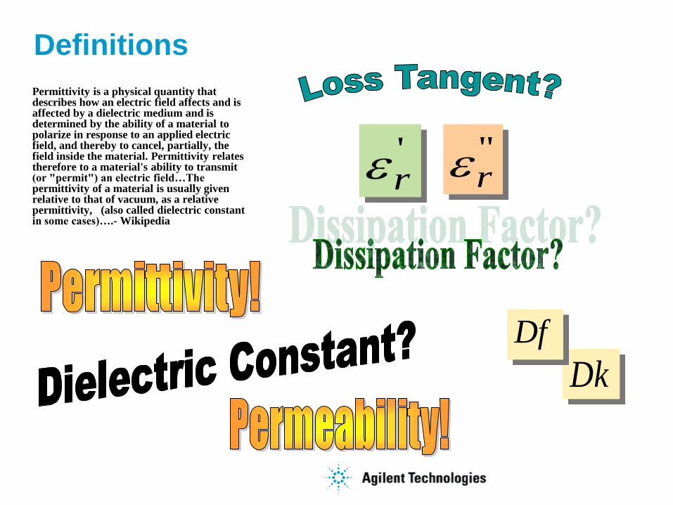
Definitions
Permittivity is a physical quantity that describes how an electric field affects and is affected by a dielectric medium and is determined by the ability of a material to polarize in response to an applied electric field, and thereby to cancel, partially, the field inside the material. Permittivity relates therefore to a material's ability to transmit (or "permit") an electric field…The permittivity of a material is usually given relative to that of vacuum, as a relative permittivity, (also called dielectric constant in some cases)….- Wikipedia
Dk
Df
'r
"r
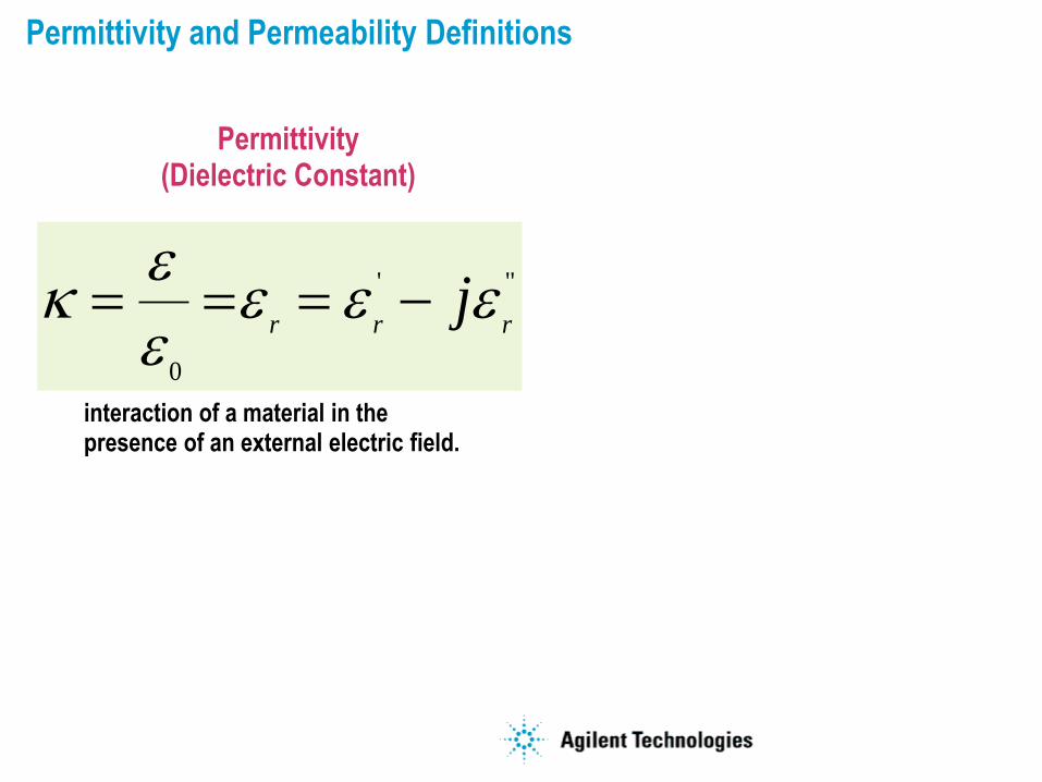
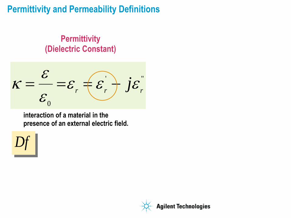
Permittivity and Permeability Definitions
interaction of a material in the presence of an external electric field.
"'
0
rrrj
Permittivity (Dielectric Constant)
Permittivity and Permeability Definitions
interaction of a material in the presence of an external electric field.
"'
0
rrrj
Permittivity (Dielectric Constant)
Df
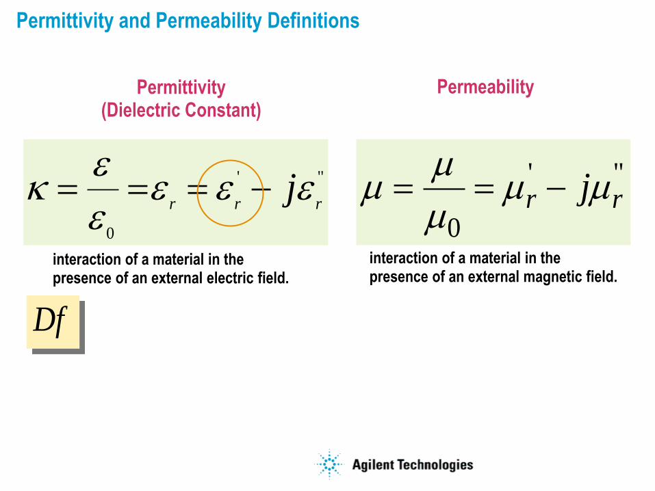
Permittivity and Permeability Definitions
interaction of a material in the presence of an external electric field.
"'
0
rrrj
"'
0rr j
interaction of a material in the presence of an external magnetic field.
Permittivity (Dielectric Constant)
Permeability
Df
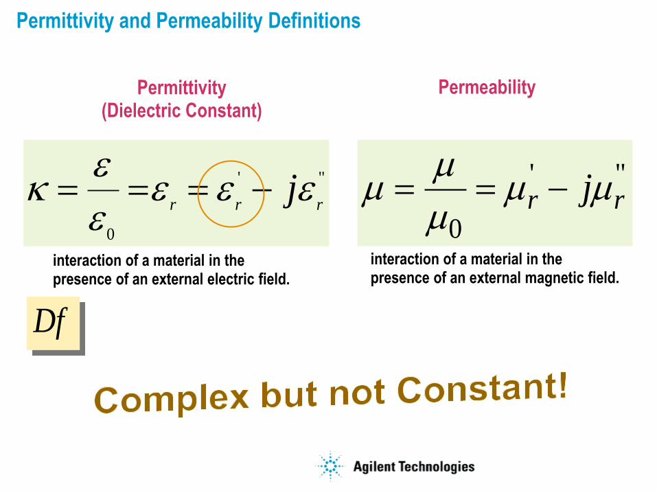
Permittivity and Permeability Definitions
interaction of a material in the presence of an external electric field.
"'
0
rrrj
"'
0rr j
interaction of a material in the presence of an external magnetic field.
Permittivity (Dielectric Constant)
Permeability
Df
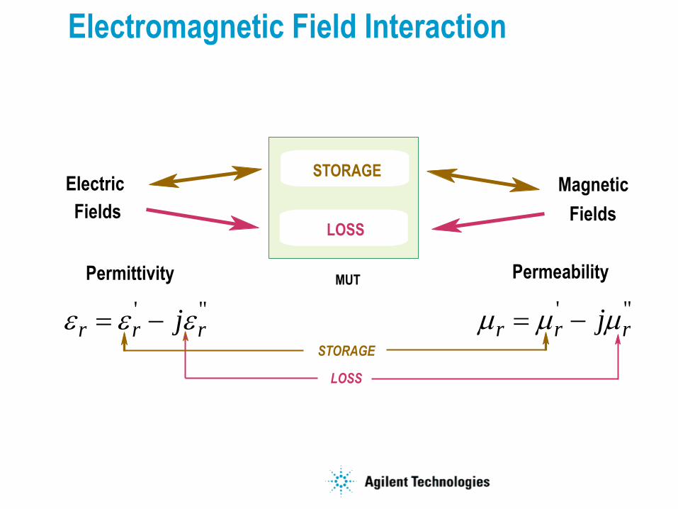
"'rrr j "'
rrr j
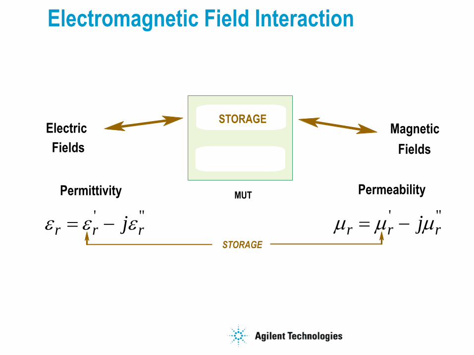
Electromagnetic Field Interaction
Electric Magnetic
Permittivity Permeability
FieldsFields
STORAGE
MUT
STORAGE
"'rrr j "'
rrr j
Electromagnetic Field Interaction
Electric Magnetic
Permittivity Permeability
FieldsFields
STORAGE
LOSS
MUT
STORAGE
LOSS
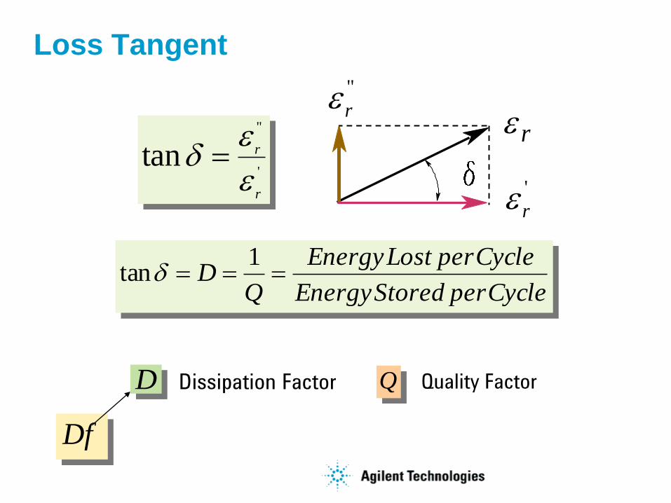
Loss Tangent
'
"
tanr
r
CycleperStoredEnergy
CycleperLostEnergy
QD
1tan
Dissipation FactorD Quality FactorQ
r
'
r
''
r
Df
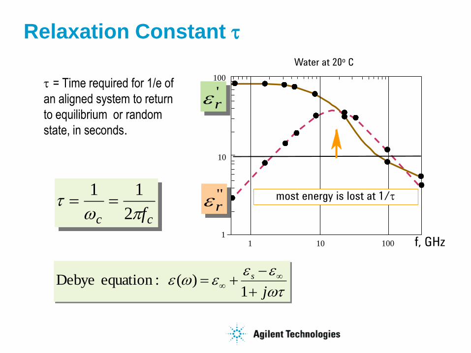
Relaxation Constant t
t = Time required for 1/e of
an aligned system to return
to equilibrium or random
state, in seconds.
cc ft
2
11
11
10
100
10 100
Water at 20o C
f, GHz
most energy is lost at 1/t
'r
"r
t
j
s
1
)( :equation Debye
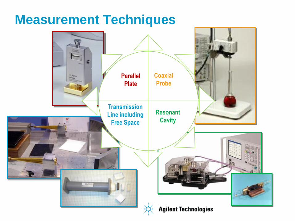
Measurement Techniques
Parallel
Plate
Resonant
Cavity
Transmission
Line including
Free Space
Coaxial
Probe

Which Technique is Best?
It Depends…
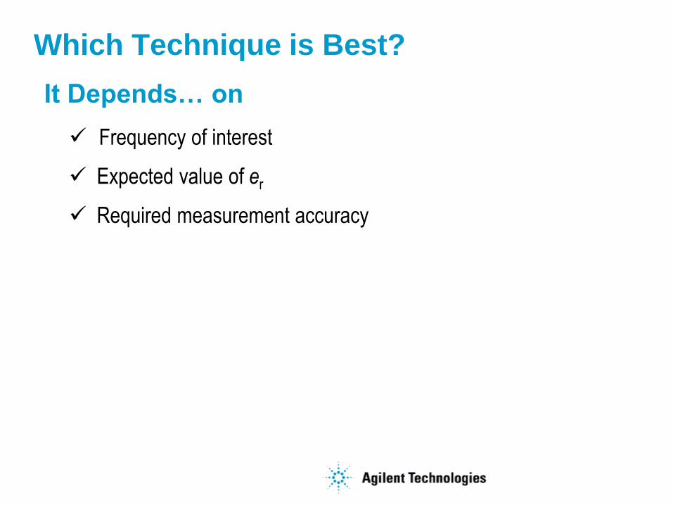
Frequency of interest
Expected value of er
Required measurement accuracy
Which Technique is Best?
It Depends… on
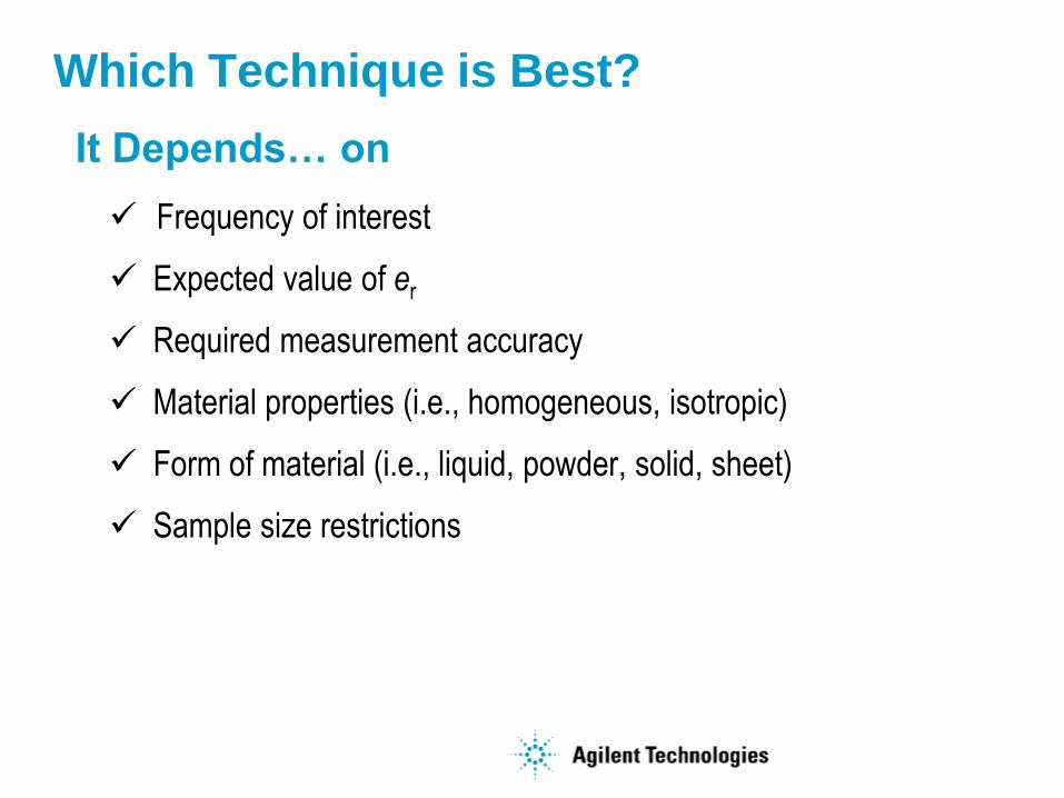
Frequency of interest
Expected value of er
Required measurement accuracy
Material properties (i.e., homogeneous, isotropic)
Form of material (i.e., liquid, powder, solid, sheet)
Sample size restrictions
Which Technique is Best?
It Depends… on
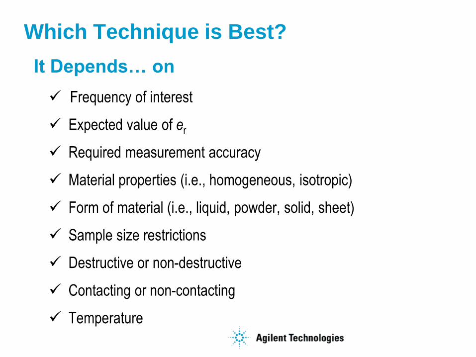
Frequency of interest
Expected value of er
Required measurement accuracy
Material properties (i.e., homogeneous, isotropic)
Form of material (i.e., liquid, powder, solid, sheet)
Sample size restrictions
Destructive or non-destructive
Contacting or non-contacting
Temperature
Which Technique is Best?
It Depends… on
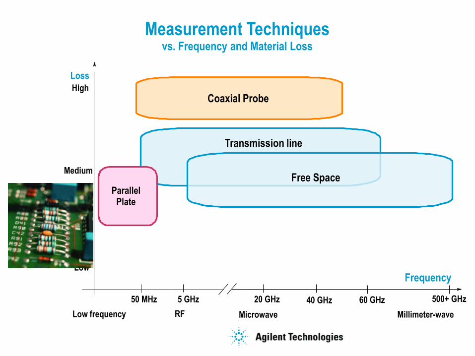
Measurement Techniques vs. Frequency and Material Loss
Parallel Plate
Frequency
Loss
Transmission line
Resonant Cavity
Coaxial Probe
MicrowaveRF Millimeter-waveLow frequency
High
Medium
Low
Free Space
50 MHz 20 GHz 40 GHz 60 GHz5 GHz 500+ GHz
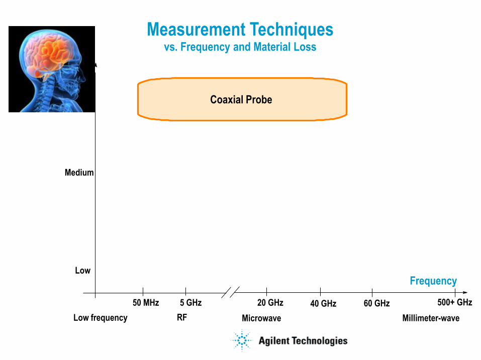
Measurement Techniques vs. Frequency and Material Loss
Frequency
Loss
Coaxial Probe
MicrowaveRF Millimeter-waveLow frequency
High
Medium
Low
50 MHz 20 GHz 40 GHz 60 GHz5 GHz 500+ GHz
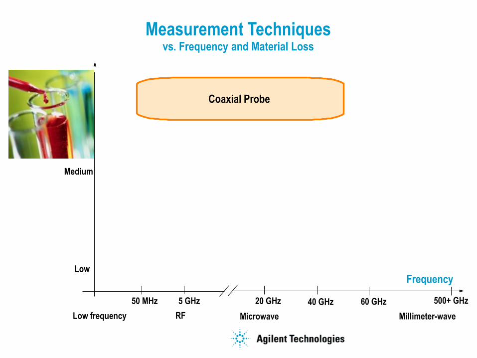
Measurement Techniques vs. Frequency and Material Loss
Frequency
Loss
Coaxial Probe
MicrowaveRF Millimeter-waveLow frequency
High
Medium
Low
50 MHz 20 GHz 40 GHz 60 GHz5 GHz 500+ GHz
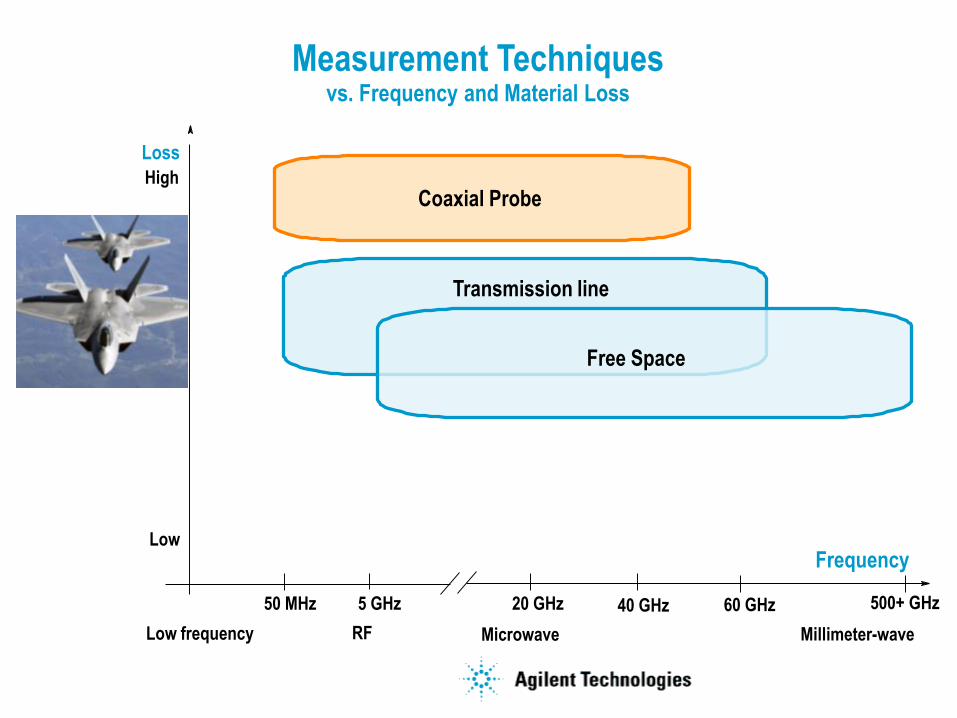
Measurement Techniques vs. Frequency and Material Loss
Frequency
Loss
Transmission line
Coaxial Probe
MicrowaveRF Millimeter-waveLow frequency
High
Medium
Low
Free Space
50 MHz 20 GHz 40 GHz 60 GHz5 GHz 500+ GHz
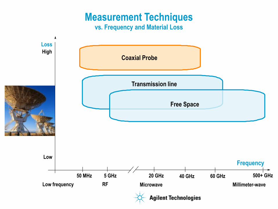
Measurement Techniques vs. Frequency and Material Loss
Frequency
Loss
Transmission line
Coaxial Probe
MicrowaveRF Millimeter-waveLow frequency
High
Medium
Low
Free Space
50 MHz 20 GHz 40 GHz 60 GHz5 GHz 500+ GHz
Measurement Techniques vs. Frequency and Material Loss
Parallel Plate
Frequency
Loss
Transmission line
Coaxial Probe
MicrowaveRF Millimeter-waveLow frequency
High
Medium
Low
Free Space
50 MHz 20 GHz 40 GHz 60 GHz5 GHz 500+ GHz
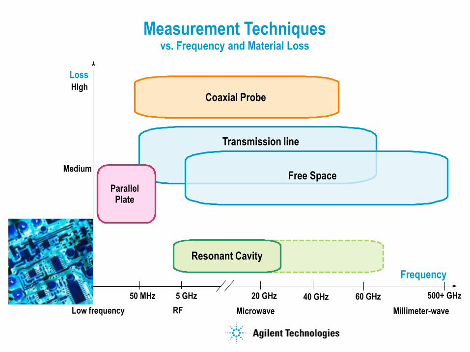
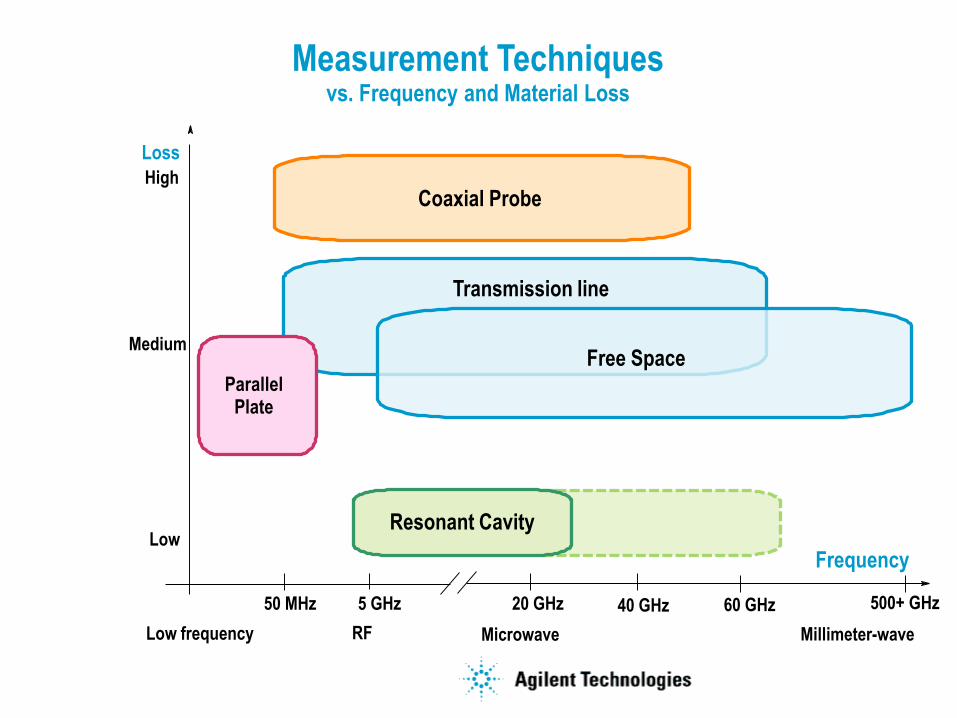
Measurement Techniques vs. Frequency and Material Loss
Parallel Plate
Frequency
Loss
Transmission line
Resonant Cavity
Coaxial Probe
MicrowaveRF Millimeter-waveLow frequency
High
Medium
Low
Free Space
50 MHz 20 GHz 40 GHz 60 GHz5 GHz 500+ GHz
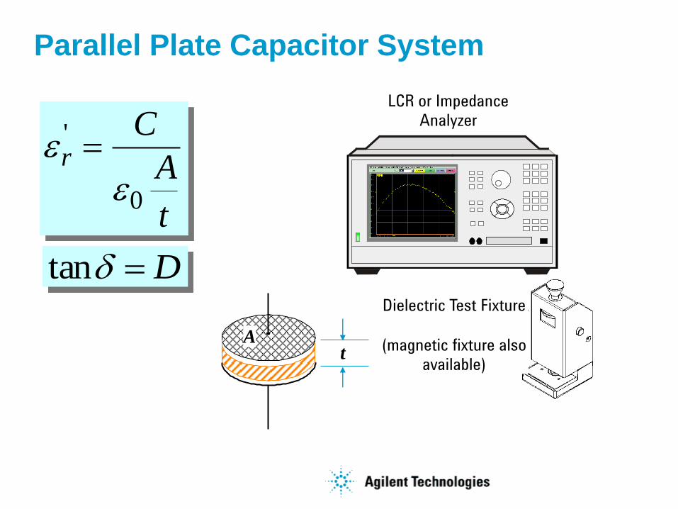
Parallel Plate Capacitor System
t
A
Cr
0
'
LCR or Impedance
Analyzer
Dielectric Test Fixture
(magnetic fixture also
available)
Dtan
tA
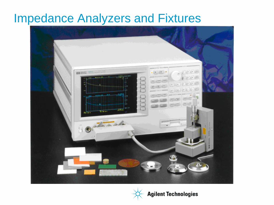
Impedance Analyzers and Fixtures
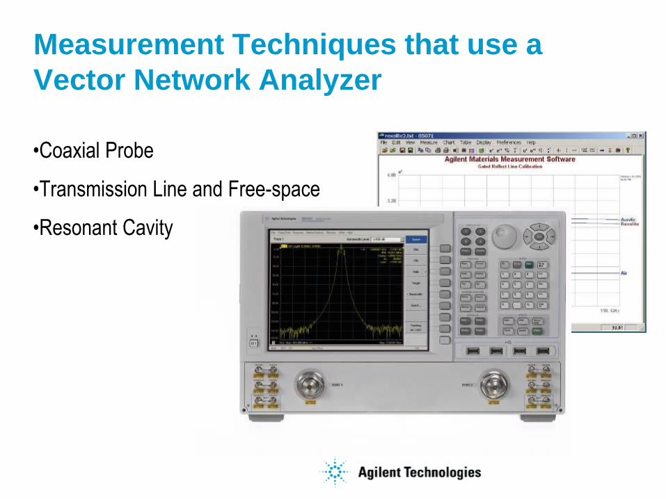
Measurement Techniques that use a
Vector Network Analyzer
•Coaxial Probe
•Transmission Line and Free-space
•Resonant Cavity
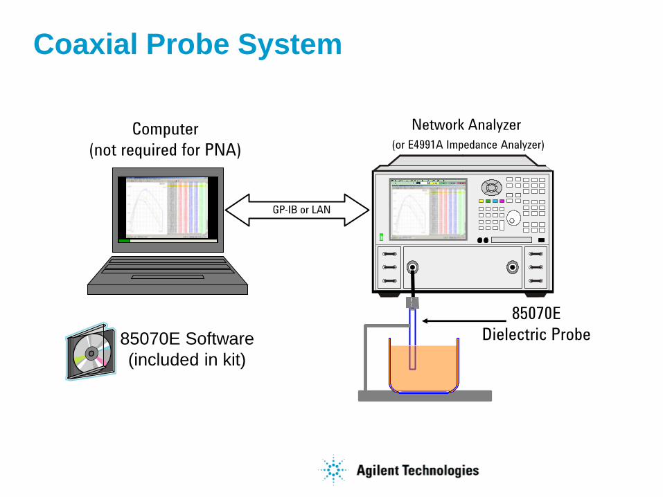
Coaxial Probe System
Network Analyzer
(or E4991A Impedance Analyzer)
85070E
Dielectric Probe
GP-IB or LAN
Computer
(not required for PNA)
85070E Software
(included in kit)
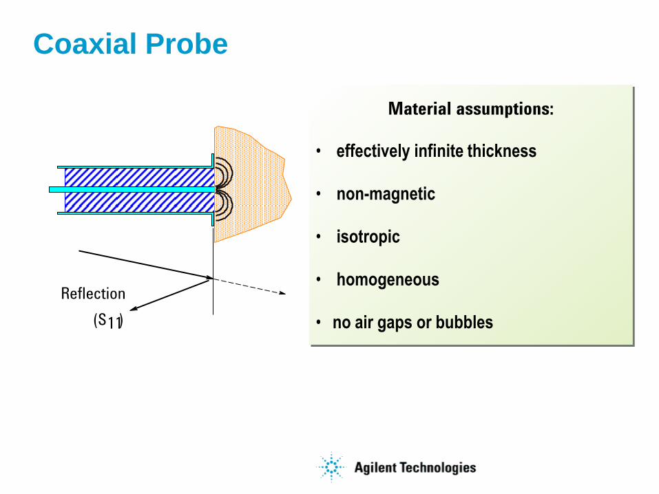
Material assumptions:
• effectively infinite thickness
• non-magnetic
• isotropic
• homogeneous
• no air gaps or bubbles
Coaxial Probe
11
Reflection
(S )
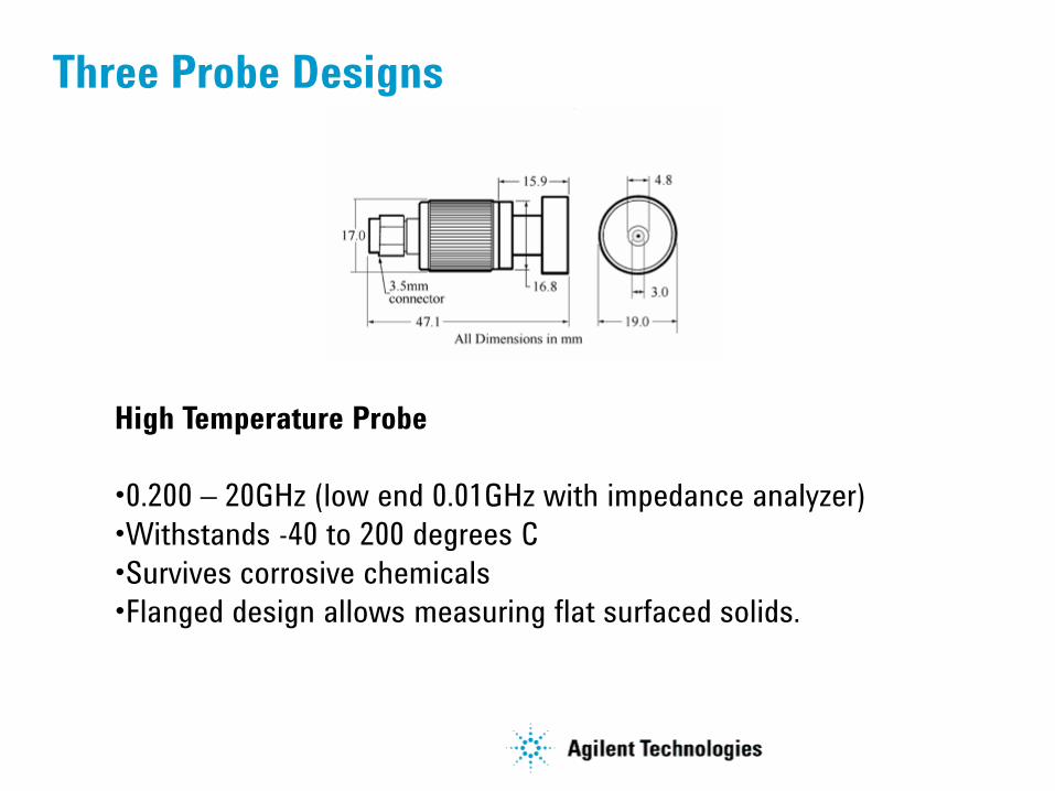
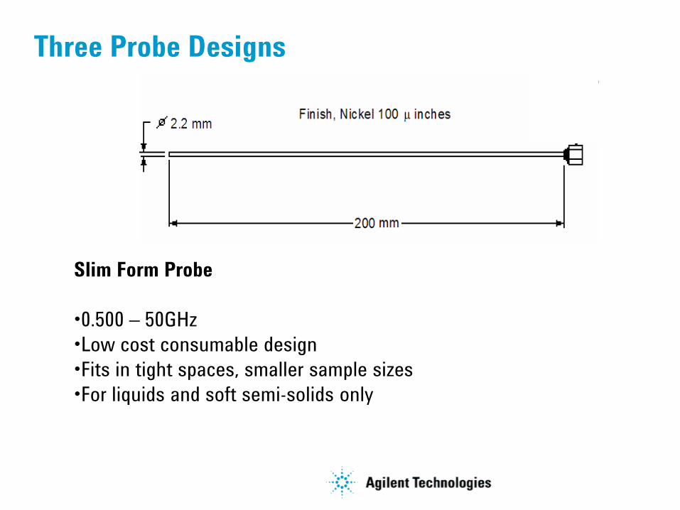
Three Probe Designs
High Temperature Probe
•0.200 – 20GHz (low end 0.01GHz with impedance analyzer)
•Withstands -40 to 200 degrees C
•Survives corrosive chemicals
•Flanged design allows measuring flat surfaced solids.
Three Probe Designs
Slim Form Probe
•0.500 – 50GHz
•Low cost consumable design
•Fits in tight spaces, smaller sample sizes
•For liquids and soft semi-solids only
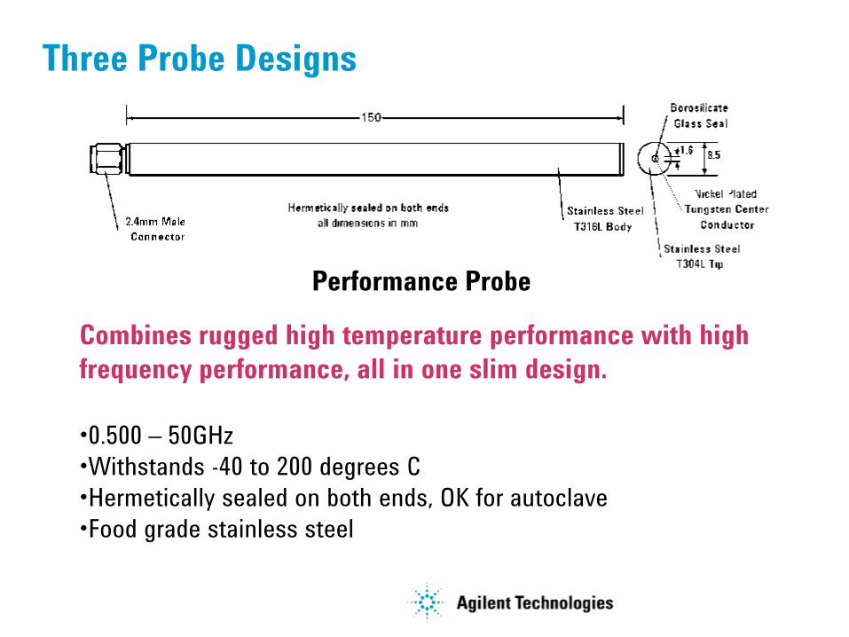
Three Probe Designs
Performance Probe
Combines rugged high temperature performance with high
frequency performance, all in one slim design.
•0.500 – 50GHz
•Withstands -40 to 200 degrees C
•Hermetically sealed on both ends, OK for autoclave
•Food grade stainless steel
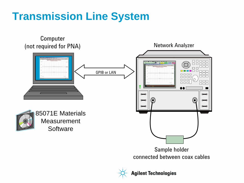
Transmission Line System
Network Analyzer
GPIB or LAN
Sample holder
connected between coax cables
Computer
(not required for PNA)
85071E Materials
Measurement
Software
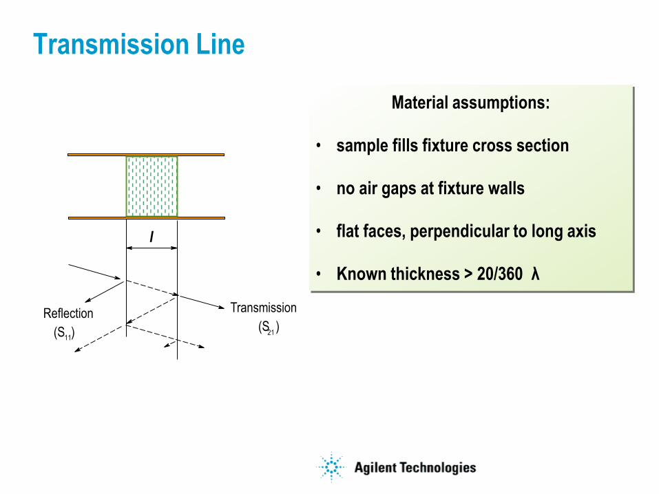
Transmission Line
l
Reflection
(S )11
Transmission
(S )21
Material assumptions:
• sample fills fixture cross section
• no air gaps at fixture walls
• flat faces, perpendicular to long axis
• Known thickness > 20/360 λ
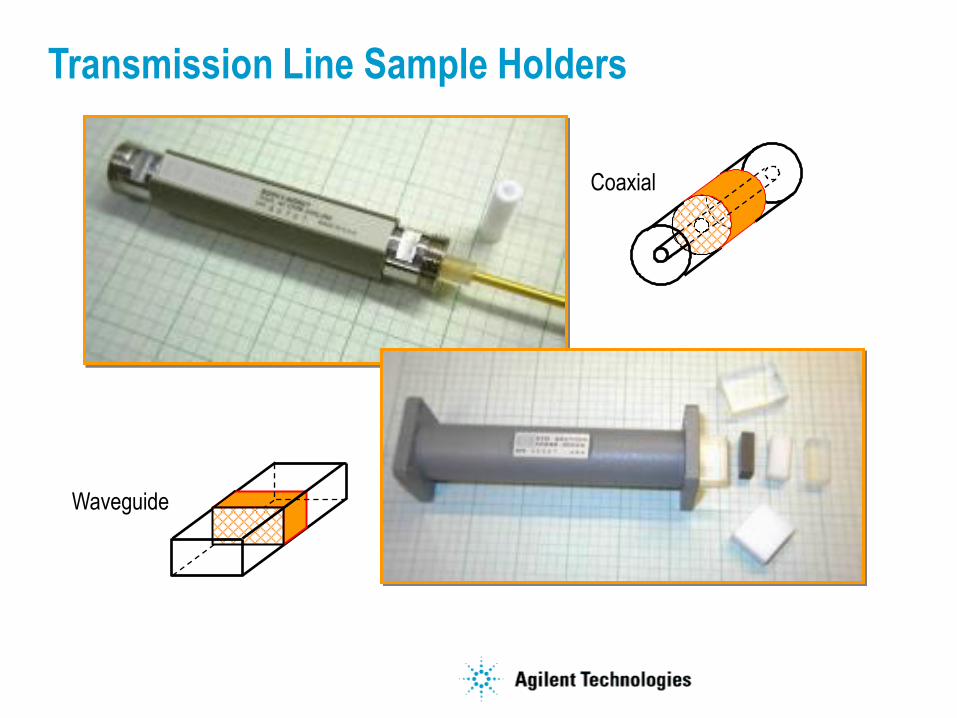
Transmission Line Sample Holders
Waveguide
Coaxial
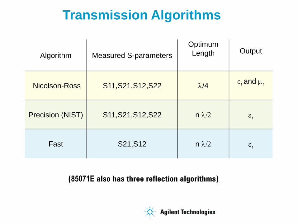
Transmission Algorithms
(85071E also has three reflection algorithms)
Algorithm Measured S-parameters
Optimum
Length Output
Nicolson-Ross S11,S21,S12,S22 l/4r and r
Precision (NIST) S11,S21,S12,S22 n l/2 r
Fast S21,S12 n l/2 r
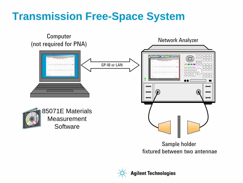
Computer
(not required for PNA)
85071E Materials
Measurement
Software
Transmission Free-Space System
GP-IB or LAN
Network Analyzer
Sample holder
fixtured between two antennae
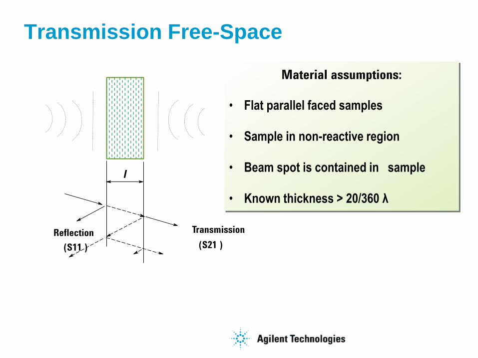
Transmission Free-Space
Material assumptions:
• Flat parallel faced samples
• Sample in non-reactive region
• Beam spot is contained in sample
• Known thickness > 20/360 λ
l
Reflection
(S11 )
Transmission
(S21 )
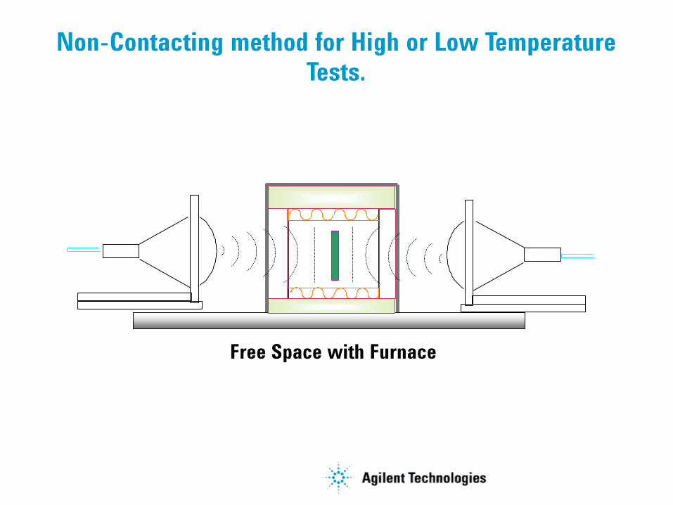
Non-Contacting method for High or Low Temperature
Tests.
Free Space with Furnace
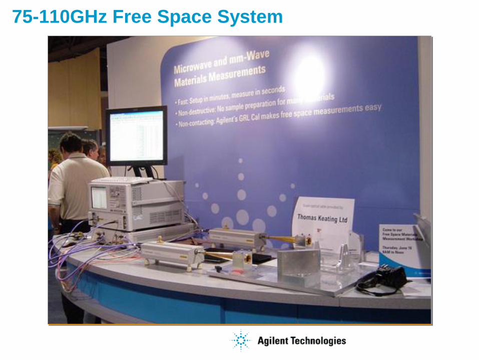
75-110GHz Free Space System
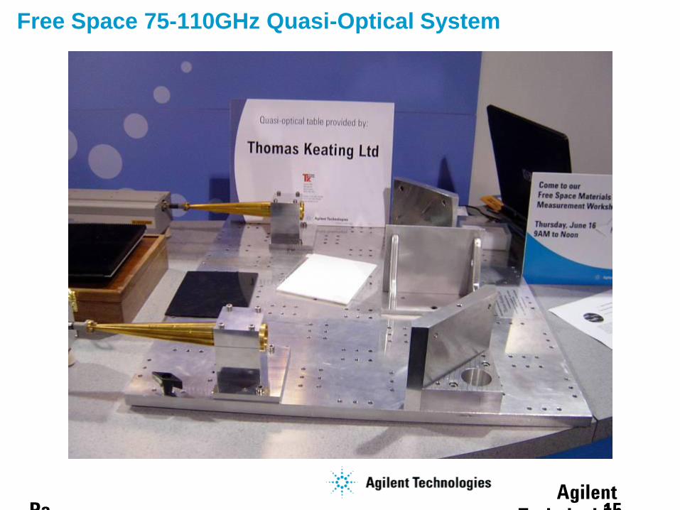
Free Space 75-110GHz Quasi-Optical System
Agilent
Technical Forum15 Pa

Free Space 75-110GHz Quasi-Optical System
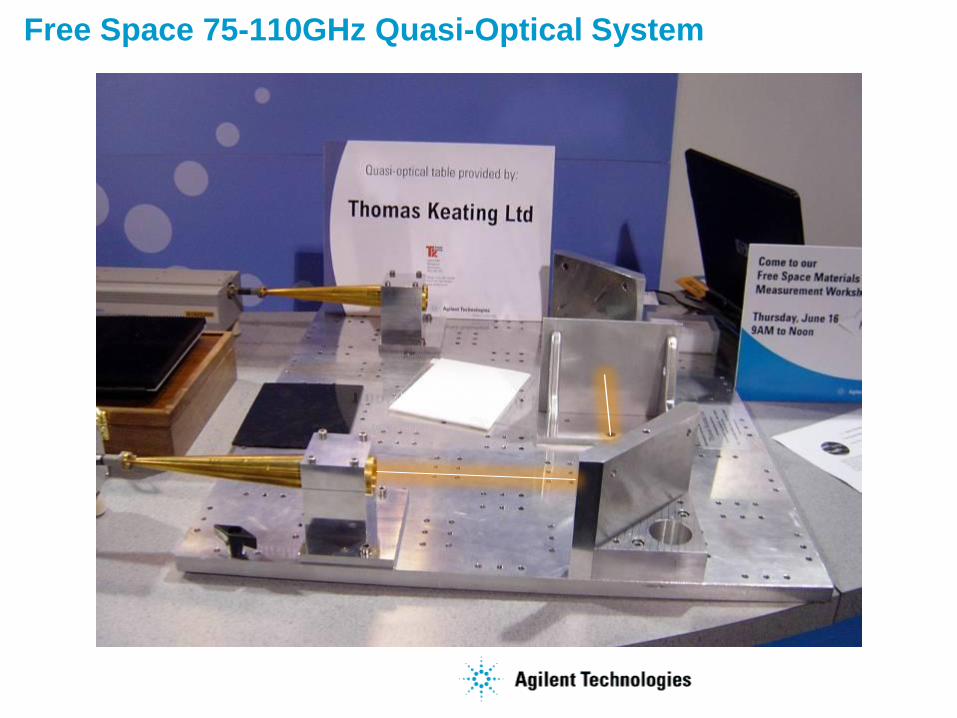
Free Space 75-110GHz Quasi-Optical System

Free Space 75-110GHz Quasi-Optical System

Free Space 75-110GHz Quasi-Optical System
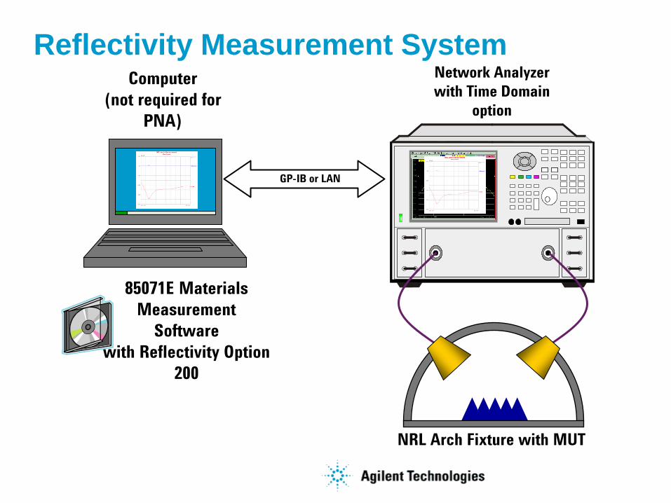
Reflectivity Measurement System
GP-IB or LAN
Network Analyzer
with Time Domain
option
NRL Arch Fixture with MUT
Computer
(not required for
PNA)
85071E Materials
Measurement
Software
with Reflectivity Option
200
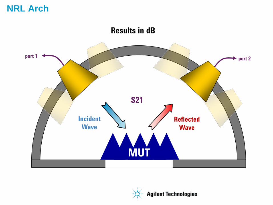
NRL Arch
Incident
WaveReflected
Wave
port 1port 2
MUT
S21
Results in dB
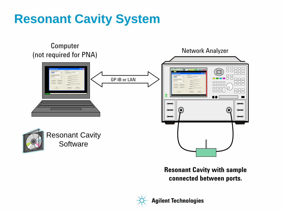
Resonant Cavity System
Resonant Cavity with sample
connected between ports.
Network Analyzer
GP-IB or LAN
Computer
(not required for PNA)
Resonant Cavity
Software
00313.011
4
2.3032
1
css
cr
ss
sccr
QQV
V
fV
ffV
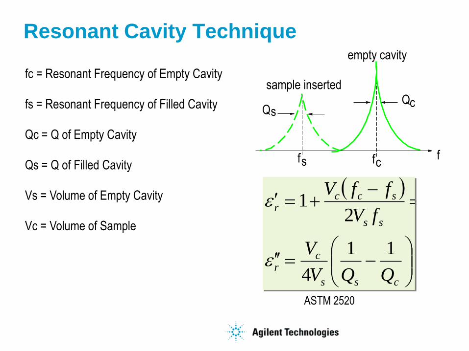
Resonant Cavity Technique
Q
fsffc
sQc
empty cavity
sample insertedfc = Resonant Frequency of Empty Cavity
fs = Resonant Frequency of Filled Cavity
Qc = Q of Empty Cavity
Qs = Q of Filled Cavity
Vs = Volume of Empty Cavity
Vc = Volume of Sample
ASTM 2520
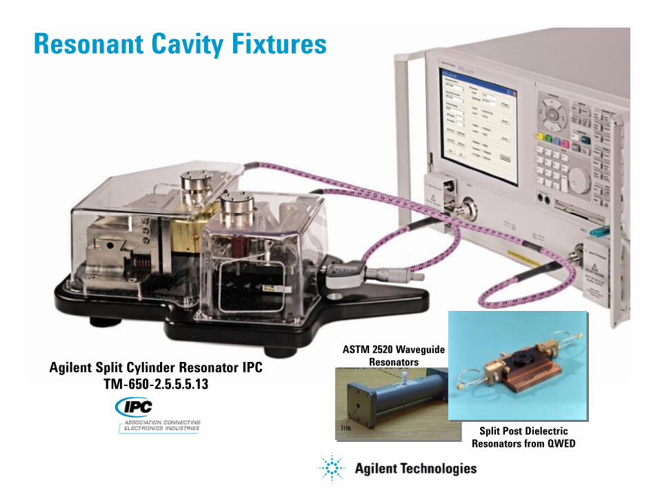
Resonant Cavity Fixtures
Agilent Split Cylinder Resonator IPC
TM-650-2.5.5.5.13
Split Post Dielectric
Resonators from QWED
ASTM 2520 Waveguide
Resonators
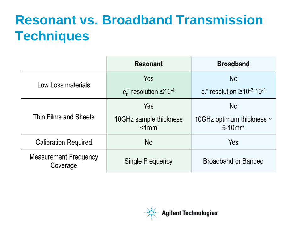
Resonant vs. Broadband Transmission
Techniques
Resonant Broadband
Low Loss materialsYes
er” resolution ≤10-4
No
er” resolution ≥10-2-10-3
Thin Films and Sheets
Yes
10GHz sample thickness <1mm
No
10GHz optimum thickness ~ 5-10mm
Calibration Required No Yes
Measurement Frequency Coverage
Single Frequency Broadband or Banded
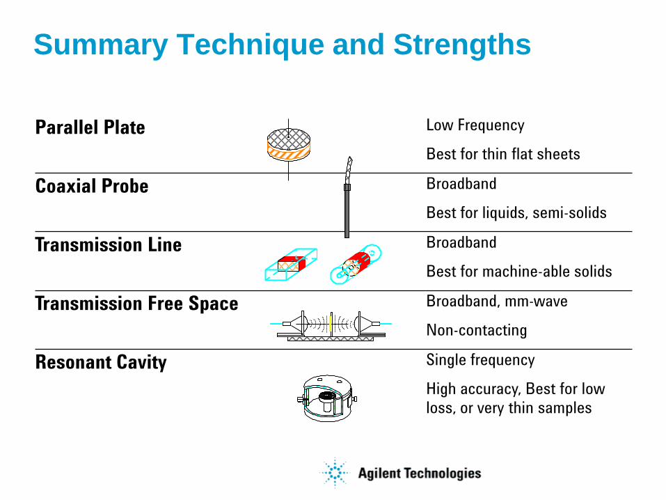
Summary Technique and Strengths
Parallel Plate Low Frequency
Best for thin flat sheets
Coaxial Probe Broadband
Best for liquids, semi-solids
Transmission Line Broadband
Best for machine-able solids
Transmission Free Space Broadband, mm-wave
Non-contacting
Resonant Cavity Single frequency
High accuracy, Best for low
loss, or very thin samples
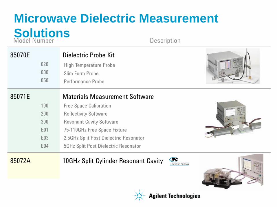
Microwave Dielectric Measurement
SolutionsModel Number Description
85070E
020
030
050
Dielectric Probe Kit
High Temperature Probe
Slim Form Probe
Performance Probe
85071E
100
200
300
E01
E03
E04
Materials Measurement Software
Free Space Calibration
Reflectivity Software
Resonant Cavity Software
75-110GHz Free Space Fixture
2.5GHz Split Post Dielectric Resonator
5GHz Split Post Dielectric Resonator
85072A 10GHz Split Cylinder Resonant Cavity

For More Information
Visit our website at:
www.agilent.com/find/materials
For Product Overviews, Application Notes, Manuals,
Quick Quotes, international contact information…

For More Information
Visit our website at:
www.agilent.com/find/materials
Call our on-line technical support:
+1 800 829-4444
For Product Overviews, Application Notes, Manuals,
Quick Quotes, international contact information…
For personal help for your application, formal quotes, to
get in touch with Agilent field engineers in your area.

References
R N Clarke (Ed.), “A Guide to the Characterisation of DielectricMaterials at RF and Microwave Frequencies,” Published by The
Institute of Measurement & Control (UK) & NPL, 2003
J. Baker-Jarvis, M.D. Janezic, R.F. Riddle, R.T. Johnk, P. Kabos, C. Holloway, R.G. Geyer, C.A. Grosvenor, “Measuring the
Permittivity and Permeability of Lossy Materials: Solids, Liquids, Metals, Building Materials, and Negative-Index Materials,” NIST
Technical Note 15362005
“Test methods for complex permittivity (Dielectric Constant) of solid electrical insulating materials at microwave frequencies and
temperatures to 1650 , ” ASTM Standard D2520, American Society for Testing and Materials
Janezic M. and Baker-Jarvis J., “Full-wave Analysis of a Split-Cylinder Resonator for Nondestructive Permittivity Measurements,” IEEE
Transactions on Microwave Theory and Techniques vol. 47, no. 10, Oct 1999, pg. 2014-2020
J. Krupka , A.P. Gregory, O.C. Rochard, R.N. Clarke, B. Riddle, J. Baker-Jarvis, “Uncertainty of Complex Permittivity Measurement by
Split-Post Dielectric Resonator Techniques,” Journal of the European Ceramic Society
No. 10, 2001, pg. 2673-2676
“Basics of Measureing the Dielectric Properties of Materials”. Agilent application note. 5989-2589EN, April 28, 2005


![[Reservor]Petroleum Reservoir Engineering Physical Propertie](https://img.pdfslide.us/doc/110x75/5695d3801a28ab9b029e25af/reservorpetroleum-reservoir-engineering-physical-propertie.jpg)