Embed Size (px)
Citation preview
Electromagnetic Electromagnetic Formation FlightFormation Flight
6th Annual MeetingOctober 19-20, 2004
October 29, 2004 26th Annual Meeting
EMFFTeam MembersTeam Members
• Dr. Ray Sedwick, PI• Prof. Dave Miller, Co-I
• Completed Dissertations– Dr. Edmund Kong– Dr. Laila Elias
• Current Doctoral Students– Samuel Schweighart– Umair Ahsun
• Current Masters Students– Daniel Kwon– Matthew Neave
• Undergraduate Researchers– Jr/Sr Design Class (15)– Amado DeHoyos– Laura Condon– Dawn Wheeler
• Industry Partners– Payload Systems, Inc– Benjamin Schweighart
• Sponsorship– NIAC, NASA JPL (TPF)– NRO DII, DARPA TTO– Lockheed IRAD
October 29, 2004 36th Annual Meeting
EMFFOutlineOutline
• Introduction– Background/Concept– Criticisms/Responses– Research Approach
• Feasibility Issues– How far apart does it work?– Thermal Design– Dipole Solutions
• EMFF Laboratory Demonstration– Basic laboratory setup– Critical enabling technologies– EMFF vehicle design description– Performance videos
• Conclusions/Wrap-up
October 29, 2004 46th Annual Meeting
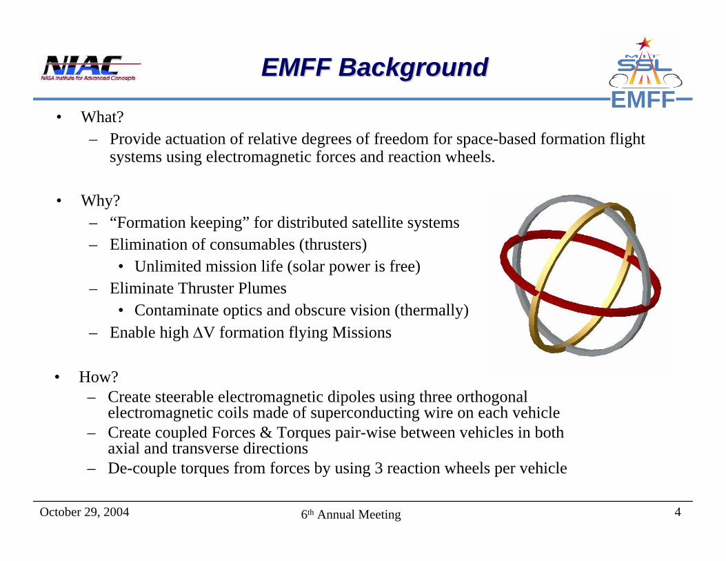
EMFFEMFF BackgroundEMFF Background
• What?– Provide actuation of relative degrees of freedom for space-based formation flight
systems using electromagnetic forces and reaction wheels.
• Why?– “Formation keeping” for distributed satellite systems– Elimination of consumables (thrusters)
• Unlimited mission life (solar power is free)– Eliminate Thruster Plumes
• Contaminate optics and obscure vision (thermally)– Enable high ∆V formation flying Missions
• How?– Create steerable electromagnetic dipoles using three orthogonal
electromagnetic coils made of superconducting wire on each vehicle– Create coupled Forces & Torques pair-wise between vehicles in both
axial and transverse directions– De-couple torques from forces by using 3 reaction wheels per vehicle
October 29, 2004 56th Annual Meeting
EMFFEMFF Concept AnimationEMFF Concept Animation
• Roll video…
October 29, 2004 66th Annual Meeting
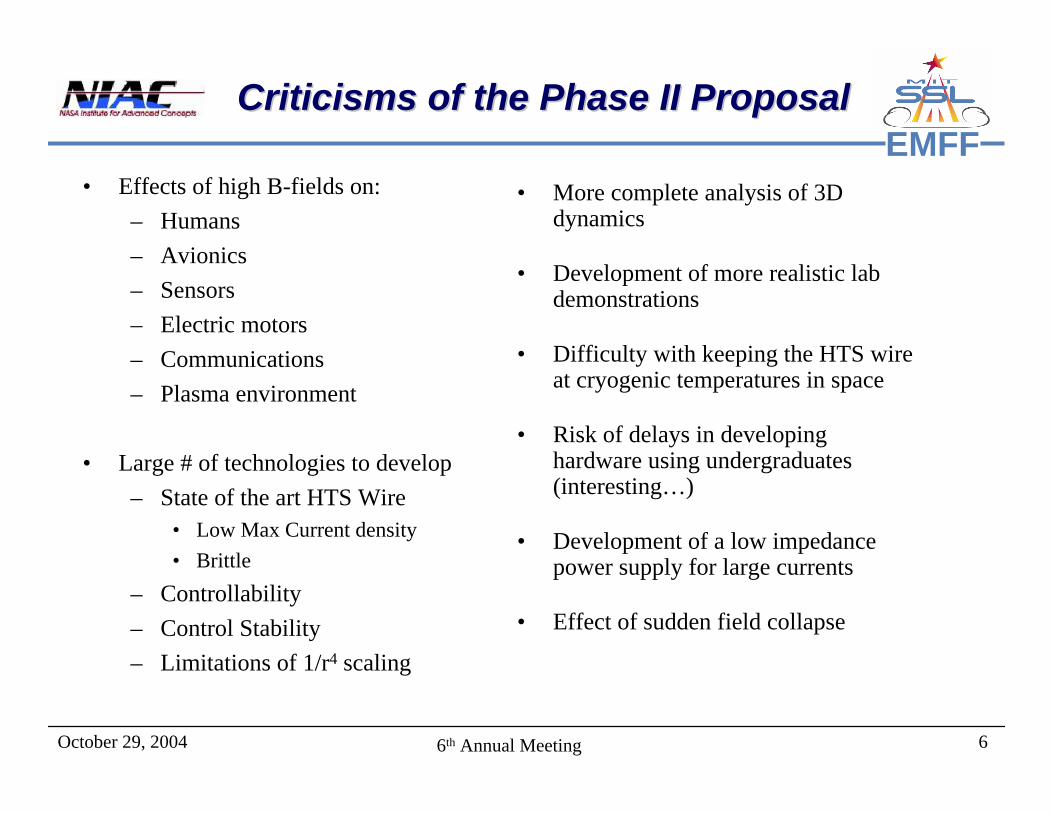
EMFFCriticisms of the Phase II ProposalCriticisms of the Phase II Proposal
• Effects of high B-fields on:– Humans– Avionics– Sensors– Electric motors– Communications– Plasma environment
• Large # of technologies to develop– State of the art HTS Wire
• Low Max Current density• Brittle
– Controllability– Control Stability– Limitations of 1/r4 scaling
• More complete analysis of 3D dynamics
• Development of more realistic lab demonstrations
• Difficulty with keeping the HTS wire at cryogenic temperatures in space
• Risk of delays in developing hardware using undergraduates (interesting…)
• Development of a low impedance power supply for large currents
• Effect of sudden field collapse
October 29, 2004 76th Annual Meeting
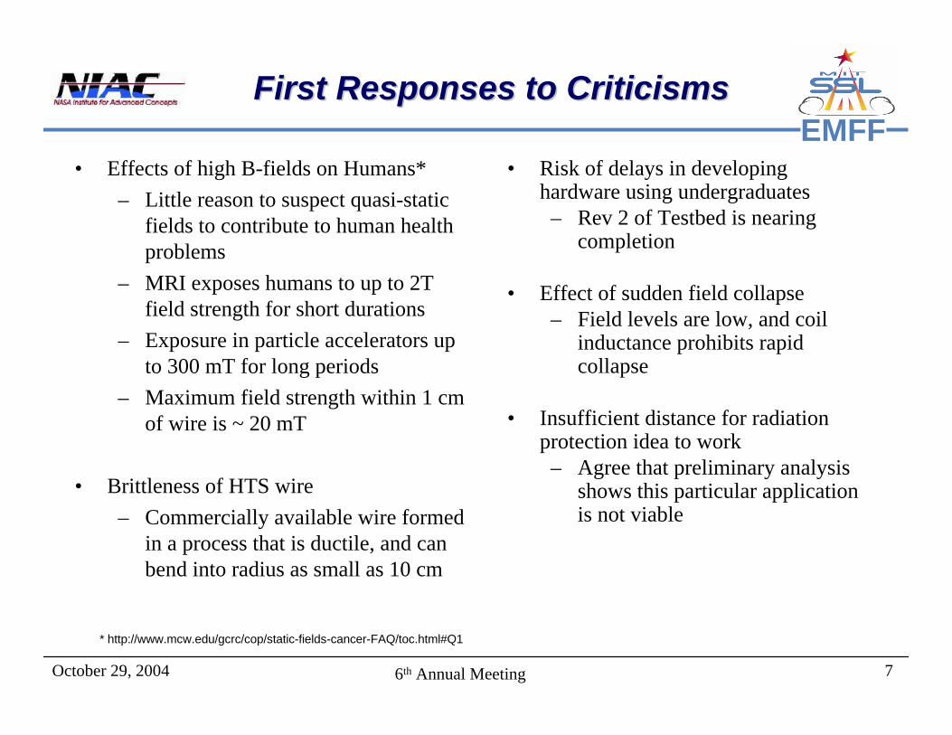
EMFFFirst Responses to CriticismsFirst Responses to Criticisms
• Effects of high B-fields on Humans*– Little reason to suspect quasi-static
fields to contribute to human health problems
– MRI exposes humans to up to 2T field strength for short durations
– Exposure in particle accelerators up to 300 mT for long periods
– Maximum field strength within 1 cm of wire is ~ 20 mT
• Brittleness of HTS wire – Commercially available wire formed
in a process that is ductile, and can bend into radius as small as 10 cm
• Risk of delays in developing hardware using undergraduates– Rev 2 of Testbed is nearing
completion
• Effect of sudden field collapse– Field levels are low, and coil
inductance prohibits rapid collapse
• Insufficient distance for radiation protection idea to work– Agree that preliminary analysis
shows this particular application is not viable
* http://www.mcw.edu/gcrc/cop/static-fields-cancer-FAQ/toc.html#Q1
October 29, 2004 86th Annual Meeting
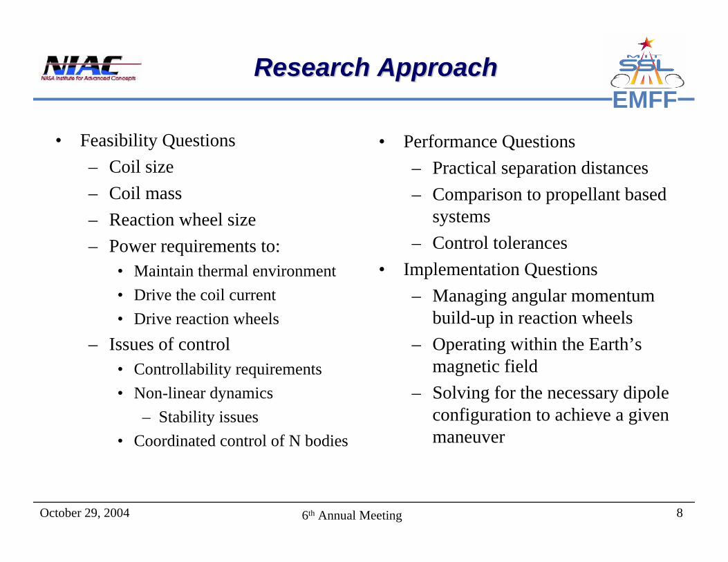
EMFFResearch ApproachResearch Approach
• Feasibility Questions– Coil size– Coil mass– Reaction wheel size– Power requirements to:
• Maintain thermal environment• Drive the coil current• Drive reaction wheels
– Issues of control• Controllability requirements• Non-linear dynamics
– Stability issues• Coordinated control of N bodies
• Performance Questions– Practical separation distances– Comparison to propellant based
systems– Control tolerances
• Implementation Questions– Managing angular momentum
build-up in reaction wheels– Operating within the Earth’s
magnetic field– Solving for the necessary dipole
configuration to achieve a given maneuver
October 29, 2004 96th Annual Meeting
EMFFOutlineOutline
• Introduction– Background/Concept– Criticisms/Responses– Research Approach
• Feasibility Issues– How far apart does it work?– Thermal Design– Dipole Solutions
• EMFF Laboratory Demonstration– Basic laboratory setup– Critical enabling technologies– EMFF vehicle design description– Performance videos
• Conclusions/Wrap-up

October 29, 2004 106th Annual Meeting
EMFFHow Far Apart Will They Work?How Far Apart Will They Work?
• Writing the force in terms of the coil radius (R), separation distance (d) and total loop current (IT), the force scales as
• We see that for a given coil current, the system scales ‘photographically’, meaning that two systems with the same loop current that are simply scaled versions of one another will have the same force
• For design, it is of interest to re-write in terms of coil mass and radius, and physical constants:
• The current state-of-the-art HTS wire has a value of
And the product of coil mass and radius becomes the design parameter.
42
03~2 T
RF Id
π µ ⎛ ⎞⎜ ⎟⎝ ⎠
22 47 2
0 4
3 3 1~ (10 ) ( )2 2 2
C C CC C
M I IRF M RR d d
π µπ ρ
− ⎛ ⎞⎛ ⎞ ⎛ ⎞ = ⎜ ⎟⎜ ⎟⎜ ⎟⎝ ⎠⎝ ⎠ ⎝ ⎠
16, 250 /CI A m kgρ
⎛ ⎞= −⎜ ⎟
⎝ ⎠

October 29, 2004 116th Annual Meeting
EMFFForce vs. Separation Distance
1.0E-04
1.0E-03
1.0E-02
1.0E-01
1.0E+00
1.0E+01
1.0E+02
1.0E+03
1 10 100
Separation (m)
Fo
rce (
N)
MR = 0.1MR = 0.3MR = 1MR = 3MR = 10MR = 30MR = 100MR = 300
kg-m
EMFORCE Testbed
EMFF Effectiveness GraphsEMFF Effectiveness Graphs
With further simplification:2
4
1~ 31.2 ( )C CF M Rd
The graph to the right shows a family of curves for various products of MC and RC
2 3-7 C
2
I3 m(10 ) = 39.6 2 kg-sρ
⎛ ⎞⎜ ⎟⎝ ⎠
2 3-7 C
2
I3 m(10 ) = 396 2 kg-sρ
⎛ ⎞⎜ ⎟⎝ ⎠
Example:• 300 kg satellite, 2 m across, needs
10 mN of thrust, want MC < 30 kg• EMFF effective up to 43 meters
Force vs. Separation Distance
1.0E-04
1.0E-03
1.0E-02
1.0E-01
1.0E+00
1.0E+01
1.0E+02
1.0E+03
1 10 100
Separation (m)
Fo
rce
(N
)
MR = 0.1MR = 0.3MR = 1MR = 3MR = 10MR = 30MR = 100MR = 300
kg-m
October 29, 2004 126th Annual Meeting
EMFFEMFF Thermal ControlEMFF Thermal Control
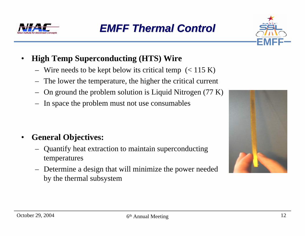
• High Temp Superconducting (HTS) Wire – Wire needs to be kept below its critical temp (< 115 K) – The lower the temperature, the higher the critical current– On ground the problem solution is Liquid Nitrogen (77 K)– In space the problem must not use consumables
• General Objectives:– Quantify heat extraction to maintain superconducting
temperatures– Determine a design that will minimize the power needed
by the thermal subsystem
October 29, 2004 136th Annual Meeting
EMFFThermal Analysis SetupThermal Analysis Setup
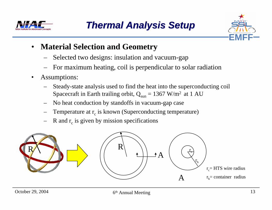
• Material Selection and Geometry– Selected two designs: insulation and vacuum-gap– For maximum heating, coil is perpendicular to solar radiation
• Assumptions: – Steady-state analysis used to find the heat into the superconducting coil
Spacecraft in Earth trailing orbit, Qsun = 1367 W/m2 at 1 AU– No heat conduction by standoffs in vacuum-gap case– Temperature at rc is known (Superconducting temperature)– R and rc is given by mission specifications
R rc
rh
R
rc= HTS wire radius
rh= container radius
A
A
October 29, 2004 146th Annual Meeting
EMFFEarth Trailing ResultsEarth Trailing Results
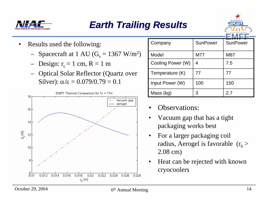
• Observations:• Vacuum gap that has a tight
packaging works best• For a larger packaging coil
radius, Aerogel is favorable (rh > 2.08 cm)
• Heat can be rejected with known cryocoolers
7.54Cooling Power (W)
7777Temperature (K)
2.73Mass (kg)
150100Input Power (W)
M87M77Model
SunPowerSunPowerCompany• Results used the following:– Spacecraft at 1 AU (Gs = 1367 W/m2)– Design: rc = 1 cm, R = 1 m– Optical Solar Reflector (Quartz over
Silver): α/ε = 0.079/0.79 = 0.1
October 29, 2004 156th Annual Meeting
EMFFLEO ResultsLEO Results
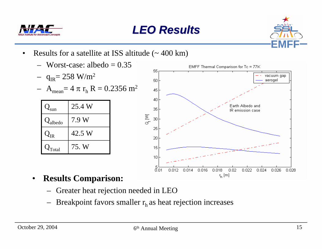
• Results for a satellite at ISS altitude (~ 400 km)– Worst-case: albedo = 0.35– qIR= 258 W/m2
– Amean= 4 π rh R = 0.2356 m2
75. WQTotal
42.5 WQIR
7.9 WQalbedo
25.4 WQsun
• Results Comparison:– Greater heat rejection needed in LEO– Breakpoint favors smaller rh as heat rejection increases
October 29, 2004 166th Annual Meeting
EMFFThe Dipole Solution ProblemThe Dipole Solution Problem
• Given an arbitrary trajectory for the satellites in formation, what are the required magnetic dipoles strengths?
• Can any force profile can be created using EMFF?– Yes, As long as the formation center of mass does not change,
and the maximum dipole strength is not reached.• Given a certain forcing profile, what is the correct amount of current
that must be run through each coil?– There are multiple solution possibilities for any given force
profile• Other Considerations
– Angular momentum distribution– Maximum dipole strength– Selection of the free dipole.

October 29, 2004 176th Annual Meeting
EMFFSolving for the DipolesSolving for the Dipoles
• The EOMs are a system of 1st and 2nd degree polynomial equations.
• Polynomial equations can be solved by– Numeric solvers (Newton’s Method)
• Must be randomly seeded• Only provides one solution• Fast
– Reduction (Groebner’s Basis)• Does not work for large systems• Very poorly conditioned numerically
– Continuation Method– Produces all solutions (Real and Imaginary)
• Time Intensive
1 1 2 2 2 3 3
1 2 2 2 3 3
1 2 2 2 3 3
( ...)
( ...)
( ...)
x x x y z x y
y x y z x y
z x y z x y
F C C C C C
C C C C C
C C C C C
µ µ µ µ µ µ
µ µ µ µ µ µ
µ µ µ µ µ µ
= + + + + + +
+ + + + + +
+ + + + +
r
October 29, 2004 186th Annual Meeting
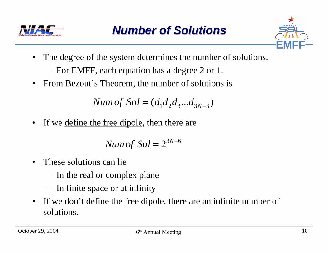
EMFFNumber of SolutionsNumber of Solutions
• The degree of the system determines the number of solutions.– For EMFF, each equation has a degree 2 or 1.
• From Bezout’s Theorem, the number of solutions is
• If we define the free dipole, then there are
• These solutions can lie– In the real or complex plane– In finite space or at infinity
• If we don’t define the free dipole, there are an infinite number of solutions.
1 2 3 3 3( ... )NNumof Sol d d d d −=
3 62 NNumof Sol −=
October 29, 2004 196th Annual Meeting
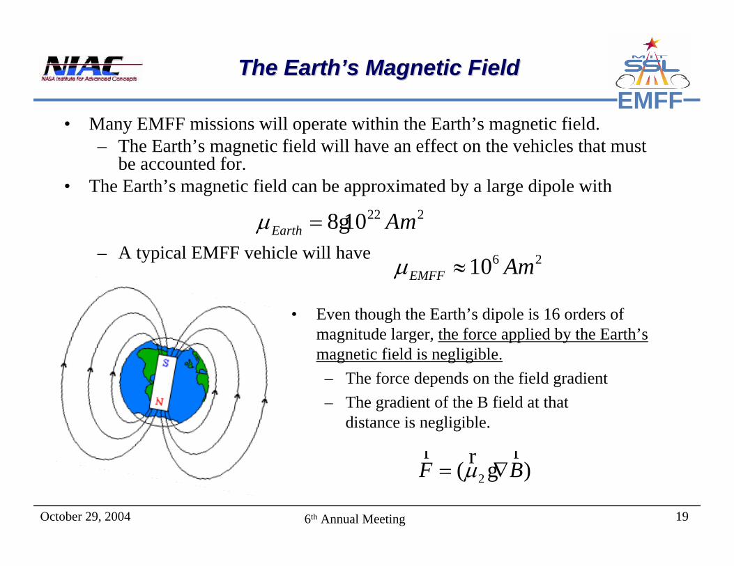
EMFFThe Earth’s Magnetic FieldThe Earth’s Magnetic Field
• Many EMFF missions will operate within the Earth’s magnetic field. – The Earth’s magnetic field will have an effect on the vehicles that must
be accounted for.• The Earth’s magnetic field can be approximated by a large dipole with
– A typical EMFF vehicle will have
• Even though the Earth’s dipole is 16 orders of magnitude larger, the force applied by the Earth’s magnetic field is negligible.– The force depends on the field gradient– The gradient of the B field at that
distance is negligible.
22 28 10Earth Amµ = g6 210EMFF Amµ ≈
2( )F Bµ= ∇r rr g
October 29, 2004 206th Annual Meeting
EMFFOutlineOutline
• Introduction– Background/Concept– Criticisms/Responses– Research Approach
• Feasibility Issues– How far apart does it work?– Thermal Design– Dipole Selection
• EMFF Laboratory Demonstration– Basic laboratory setup– Critical enabling technologies– EMFF vehicle design description– Performance videos
• Conclusions/Wrap-up
October 29, 2004 216th Annual Meeting
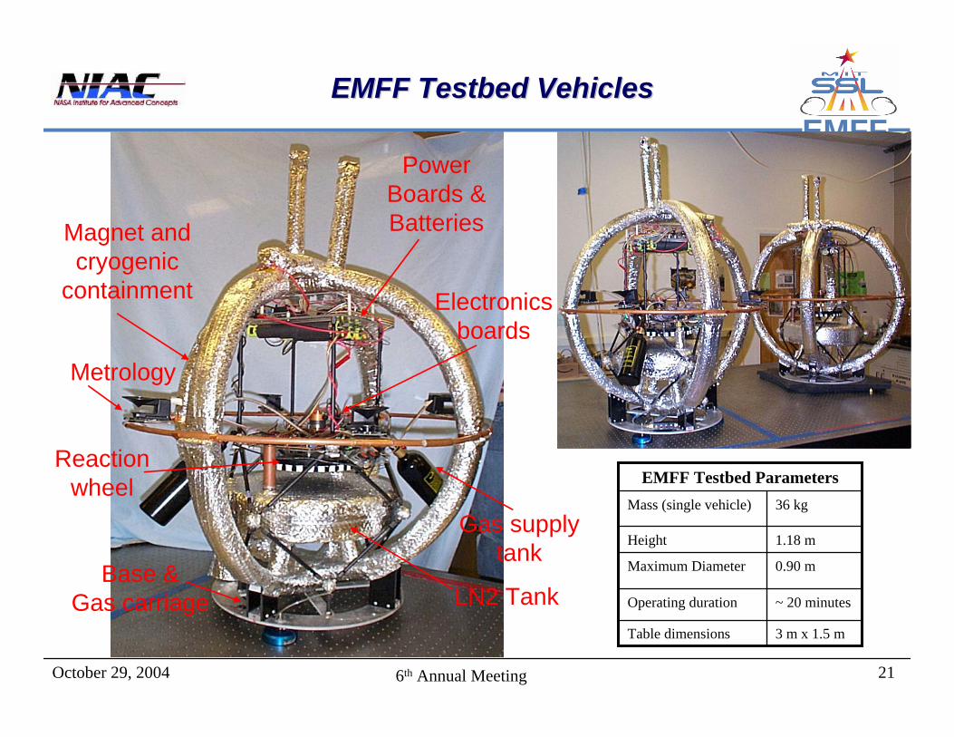
EMFFEMFF Testbed VehiclesEMFF Testbed Vehicles
EMFF Testbed Parameters
3 m x 1.5 mTable dimensions
~ 20 minutesOperating duration
0.90 mMaximum Diameter
1.18 mHeight
36 kgMass (single vehicle)
Metrology
Gas supply tank
Magnet and cryogenic
containment Electronics boards
Power Boards & Batteries
Base & Gas carriage
Reaction wheel
LN2 Tank

October 29, 2004 226th Annual Meeting
EMFFEMFF Critical TechnologiesEMFF Critical Technologies
25Distributed control
2
2
2
3
4
2
4
TRL (EMFF)
Demonstrated on EMFF Testbed
6Active and passive magnetic shielding
6Non-linear dynamics and control
2Efficient near field electromagnetic dipole interaction algorithms
6High angular momentum storage reaction wheels
6High current, low voltage power systems
9Cryogenic cooling and thermal control
6High temperature superconducting (HTS) wire
Current & Future Testbed Developments
TRL (Current)
Critical Technology
October 29, 2004 236th Annual Meeting
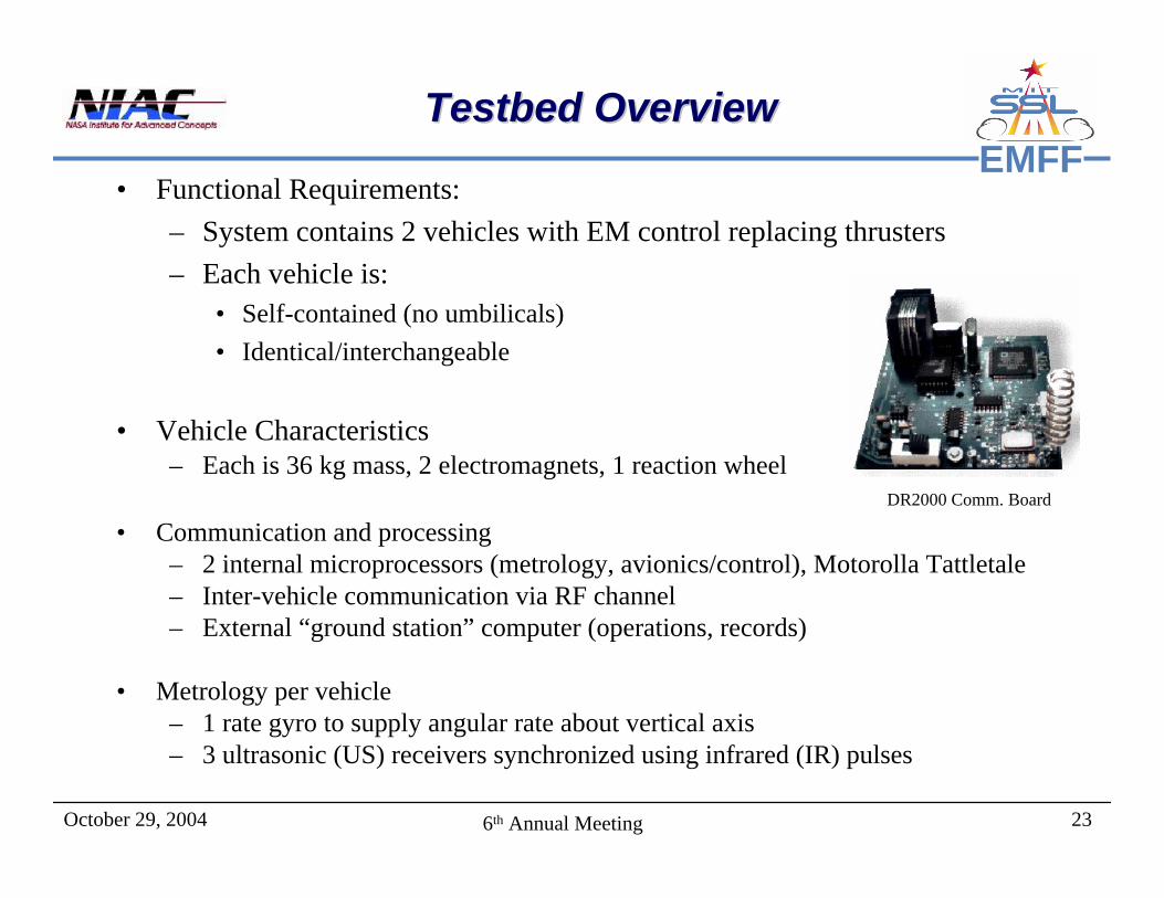
EMFFTestbed OverviewTestbed Overview
• Functional Requirements:– System contains 2 vehicles with EM control replacing thrusters– Each vehicle is:
• Self-contained (no umbilicals)• Identical/interchangeable
• Vehicle Characteristics– Each is 36 kg mass, 2 electromagnets, 1 reaction wheel
• Communication and processing– 2 internal microprocessors (metrology, avionics/control), Motorolla Tattletale– Inter-vehicle communication via RF channel– External “ground station” computer (operations, records)
• Metrology per vehicle– 1 rate gyro to supply angular rate about vertical axis– 3 ultrasonic (US) receivers synchronized using infrared (IR) pulses
DR2000 Comm. Board

October 29, 2004 246th Annual Meeting
EMFFElectromagnet DesignElectromagnet Design
• Coil wrapped with alternating layers of wire and Kapton insulation– 100 wraps– Radii of 0.375m and 0.345m
• Toroid-shaped copper casing– Operable temperature at 77 K– Filled with liquid nitrogen
• American Superconductor Bi-2223 Reinforced High Temperature Superconductor Wire– Dimensions
• 4.1 mm wide• 0.3 mm thick• 85 m length pieces
– Critical Current• 115 amps, 9.2 kA/cm2
– Below 110 K
October 29, 2004 256th Annual Meeting
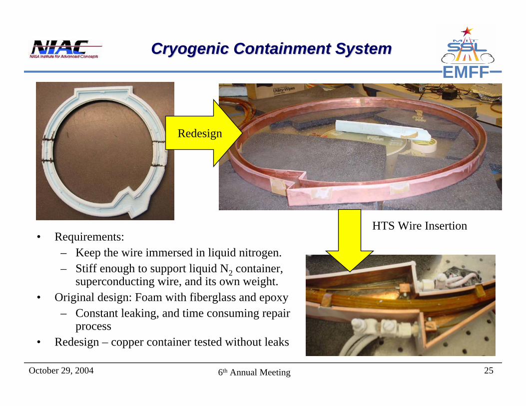
EMFFCryogenic Containment SystemCryogenic Containment System
• Requirements:– Keep the wire immersed in liquid nitrogen.– Stiff enough to support liquid N2 container,
superconducting wire, and its own weight.• Original design: Foam with fiberglass and epoxy
– Constant leaking, and time consuming repair process
• Redesign – copper container tested without leaks
Redesign
HTS Wire Insertion
October 29, 2004 266th Annual Meeting
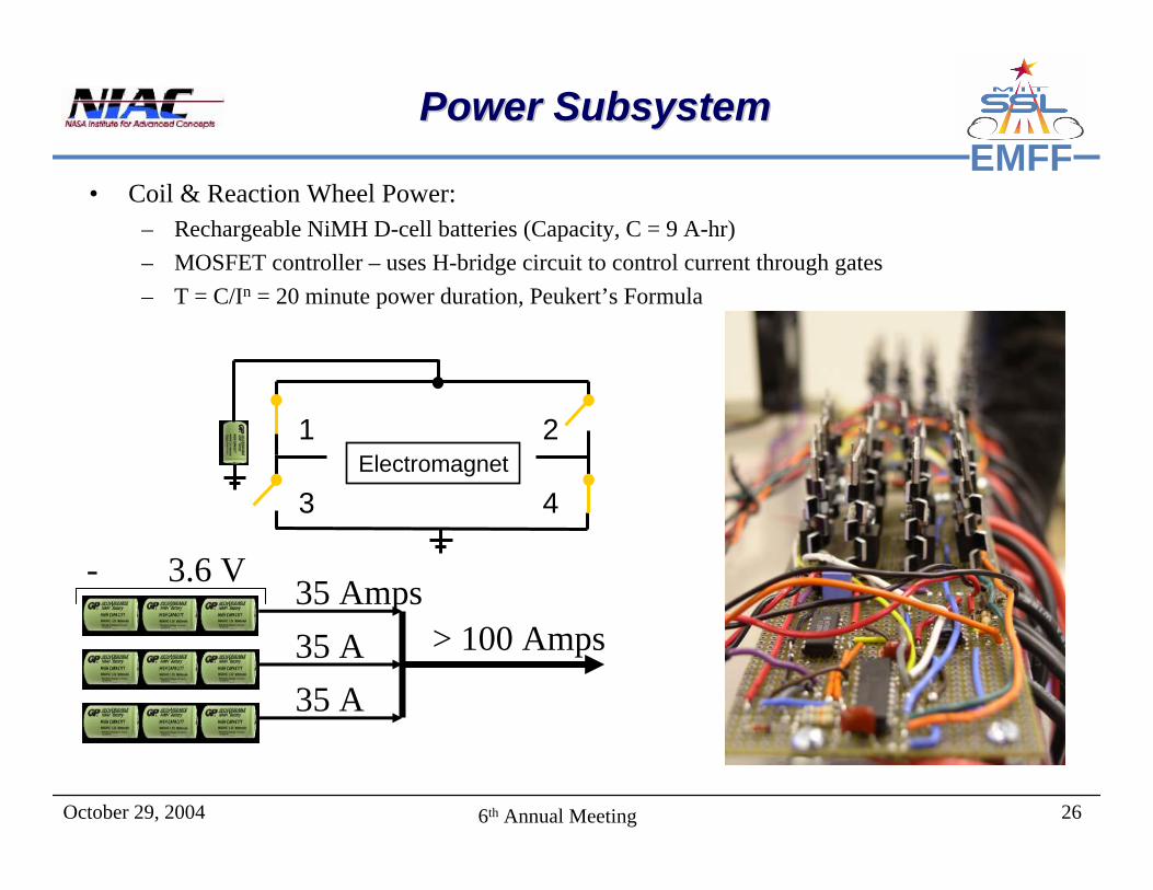
EMFFPower SubsystemPower Subsystem
• Coil & Reaction Wheel Power: – Rechargeable NiMH D-cell batteries (Capacity, C = 9 A-hr)– MOSFET controller – uses H-bridge circuit to control current through gates– T = C/In = 20 minute power duration, Peukert’s Formula
- 3.6 V + 35 Amps
35 A35 A
> 100 Amps
Electromagnet1
4
2
3

October 29, 2004 276th Annual Meeting
EMFFMore efficient High Current Control SystemMore efficient High Current Control System
• Rev2 uses a similar H-bridge design but exploits chip logic– Closes switch 3 to keep current
through electromagnet contained –free wheeling (coasting)
– Periodically pumping current• cooler (no fans needed)
Electromagnet1
4
2
3

October 29, 2004 286th Annual Meeting
EMFFAir Carriage and Reaction Wheel Air Carriage and Reaction Wheel
• Reaction Wheel– Store angular momentum– Provide counter-torques to electromagnets– Provide angular control authority– 0.23 Nm Torque at 10 Amps
• Flywheel Requirements: – non-metallic Urethane Fly Wheel– Maximum wheel velocity at 7000 RPM
• Motor tested in EM field with no variation in performance
• 2-D Friction-less environment provided by gas carriage– allows demonstration of shear forces, in concert with
reaction wheel– Porous Membrane, Flat air bearings provide pressurized
cushion of gas – CO2 gas supply: rechargeable compressed gas tank, 20
minute duration

October 29, 2004 296th Annual Meeting
EMFFTestbed Open Loop ManeuversTestbed Open Loop Maneuvers

October 29, 2004 306th Annual Meeting
EMFFTestbedTestbed Closed Loop HoldClosed Loop Hold
October 29, 2004 316th Annual Meeting
EMFFOutlineOutline
• Introduction– Background/Concept– Criticisms/Responses– Research Approach
• Feasibility Issues– How far apart does it work?– Thermal Design– Dipole Selection
• EMFF Laboratory Demonstration– Basic laboratory setup– Critical enabling technologies– EMFF vehicle design description– Performance videos
• Conclusions/Wrap-up

October 29, 2004 326th Annual Meeting
EMFFConclusionsConclusions
• Feasibility Questions Answers– Using current HTS wire, coil size and
mass are reasonable compared to what would be allocated for actuation
• This will improve over time– Reaction wheels sufficient for many
anticipated maneuvers are commercially available
– Power requirements to drive the coil current can be made quite low
– The limiting power draw is with thermal control, but is still found to be within the 100’s of Watts range
– The system is fully controllable, and linear control appears to be able to stabilize the system over large perturbations
– Techniques of extending this range using gain scheduling and other techniques are being investigated
• Performance Questions Answers– Separation distances are on the order of
several 10’s of meters at 10 mN Thrust– Systems using EMFF compare favorable
with those using propellant based actuation
• Especially as mission life (∆V) is increased
• Implementation Questions Answers– Methods for redistributing angular
momentum have been identified and are being further developed
– The Earth’s field can be used to an advantage, as one method of transporting angular momentum
– Methods of solving for the required dipole configuration have been found and methods of finding the ‘best’ configuration are being investigated
October 29, 2004 336th Annual Meeting
EMFFYear 2 PlansYear 2 Plans
• Feasibility questions have been mostly addressed
• Most of the remaining issues are ones of implementation
• B-field interactions with certain electronic components is still an issue that should be addressed– What components are affected– How difficult is it to shield them
• More detailed Design of thermal management system for use in space to keep HTS wire at cryogenic temperatures
• Automating the process of dipole selection– Trajectory planning phase– Real-time implementation phase
• Robust determination of dipole solutions for trajectory planning
• Extending stability regime by gain scheduling or other means
• Investigating other applications of EMFF and identifying other potential sources of development funding
October 29, 2004 346th Annual Meeting
EMFFOffice of Exploration Systems BAA Office of Exploration Systems BAA
• The BAA divides into 2 programs– Advance Space Technology (ASTP)– Technology Maturation (TMP)
• Under TMP is the Advanced Space Operations (ASO) Technology area– In-space Assembly/Maintenance– EVA Systems– Intelligent/Affordable On-Board Ops– Reliable/Responsive Ground Ops– Novel Space Ops Demonstrations
• Example of In Space Assembly given– Large scale (cranes)– mid-scale (robots)– Small-scale (micromanipulators)
• Focus is on systems providing– Reliable in-space deployment– Reliable in-space assembly– Intelligent/robust docking
mechanisms– Robust, autonomous rendezvous and
docking technologies and testbeds
• EMFF offers a potentially robust and reusable platform for assembly of large space structures– Can be integrated into first mission
and re-used on subsequent ones– Not as limited by size of structure as
arms or as massive as ‘cranes’– Can actuate against Earth’s field for
positioning large structures
October 29, 2004 356th Annual Meeting
EMFFApplications to Space AssemblyApplications to Space Assembly
• Roll Video…