Embed Size (px)
Citation preview
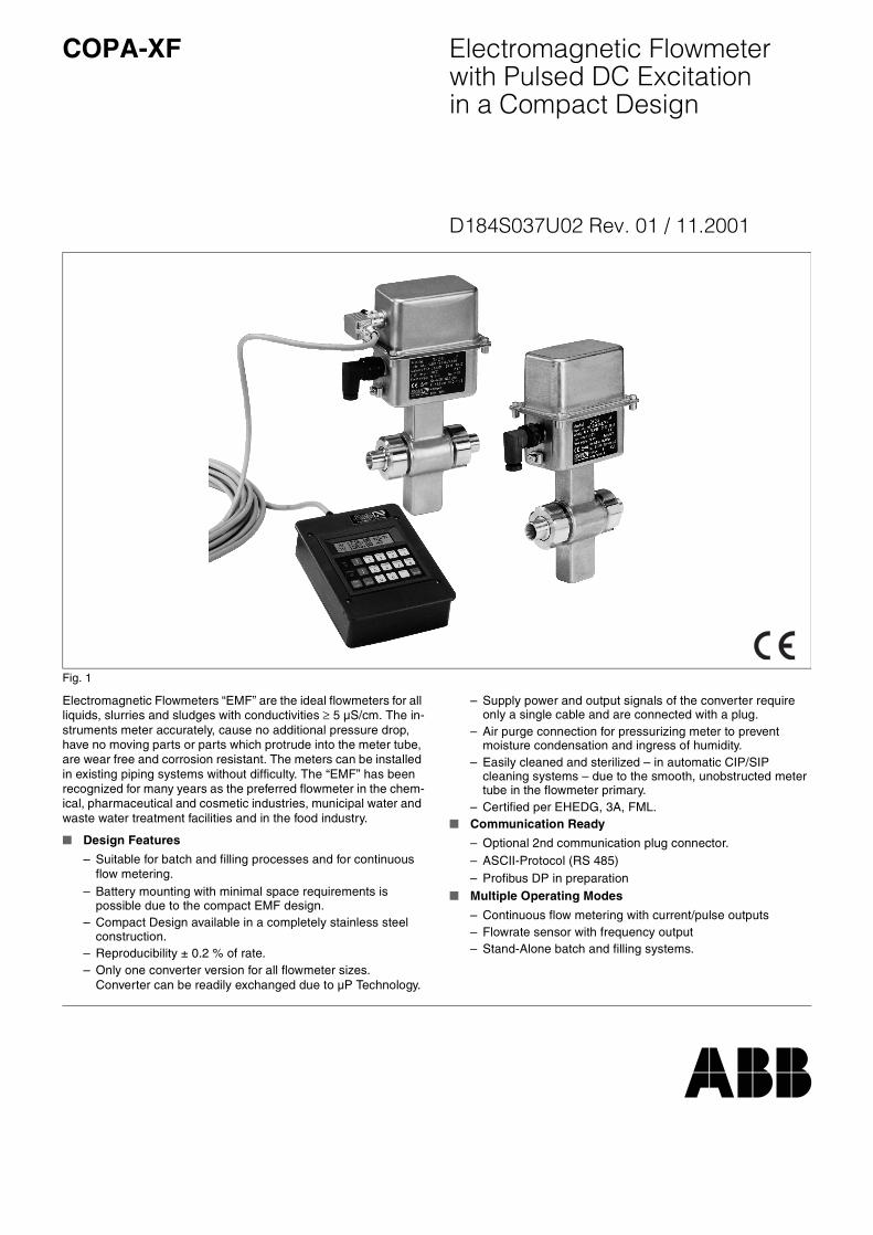
Electromagnetic Flowmeterwith Pulsed DC Excitationin a Compact Design
COPA-XF
D184S037U02 Rev. 01 / 11.2001
Electromagnetic Flowmeters “EMF” are the ideal flowmeters for all liquids, slurries and sludges with conductivities ≥ 5 µS/cm. The in-struments meter accurately, cause no additional pressure drop, have no moving parts or parts which protrude into the meter tube, are wear free and corrosion resistant. The meters can be installed in existing piping systems without difficulty. The “EMF” has been recognized for many years as the preferred flowmeter in the chem-ical, pharmaceutical and cosmetic industries, municipal water and waste water treatment facilities and in the food industry.
Design Features
– Suitable for batch and filling processes and for continuous flow metering.
– Battery mounting with minimal space requirements is possible due to the compact EMF design.
– Compact Design available in a completely stainless steel construction.
– Reproducibility ± 0.2 % of rate.– Only one converter version for all flowmeter sizes.
Converter can be readily exchanged due to µP Technology.
– Supply power and output signals of the converter require only a single cable and are connected with a plug.
– Air purge connection for pressurizing meter to prevent moisture condensation and ingress of humidity.
– Easily cleaned and sterilized – in automatic CIP/SIP cleaning systems – due to the smooth, unobstructed meter tube in the flowmeter primary.
– Certified per EHEDG, 3A, FML. Communication Ready
– Optional 2nd communication plug connector.– ASCII-Protocol (RS 485)– Profibus DP in preparation
Multiple Operating Modes
– Continuous flow metering with current/pulse outputs– Flowrate sensor with frequency output– Stand-Alone batch and filling systems.
Fig. 1

COPA-XF D184S037U02
Accuracy, Reference Conditions and Operating Principles
ConstructionA special position is filled by the electromagnetic flowmeters in the Compact Design. The converter modules (CM) are mounted di-rectly on the flowmeter primaries in this design. This results in re-duced space requirements, lower installation costs because a signal cable between the primary and the converter is no longer re-quired.
Operating PrinciplesThe basis for the electromagnetic flow metering are Faraday’s Laws of Induction which state that a voltage is induced in a conduc-tor as it moves through a magnetic field.
This principle is applied to the flow of a conductive fluid in the meter tube through which a magnetic field is generated perpendicular to the flow direction. (See Schematic Fig. 2).
The voltage induced in the fluid is measured by two diametrically oriented electrodes. The signal voltage UE is proportional to the magnetic flux density B, the electrode spacing D and the average flow velocity v.
Since the magnetic flux density B and the electrode spacing D are constant values it can be seen that a proportionality exists between the signal voltage UE at the electrodes and the average flow veloc-ity v. From the equation for volume flowrate it follows that the signal voltage UE is also linearly proportional to the volume flowrate qv.
Reference Conditions per EN 29104FluidWater, conductivity 200 µS/cm ± 10 %
Fluid Temperature20 °C ±2 K
Ambient Temperature20 °C ±2 K
Supply PowerNominal voltage per Instrument Tag UN ±1 %
Installation Requirements, Straight Pipe SectionsUpstream >10xDDownstream >5xDD = Flowmeter primary size
Warm Up Time≥ 30 Minutes
Influence on the Analog OutputSame as pulse output plus ± 0.1 % of rate
Pulse Output
Reproducibility – Batch OperationConstant operating conditions result in the improved batch accura-cies listed below. Instead of the meter/system accuracy (±0.5 % of rate Fig. 3) shown above, the batch accuracy is:
± 0.2 % for TBatch ≥ 4 s± 0.4 % for 2 s ≤ TBatch ≤ 4 s(Standard accuracy)
Reproducibility – Continuous Operation± 0.2 % of rate
UE
y
z
x
BD
E
v
Magnet Coil
Meter Tube inElectrode Plane
Signal Electrode
Signal Voltage
UE = Signal voltageB = Magnetic flux densityD = Electrode spacingv = Average flow velocityqv = Volume flowrate
qv = D
2π4
---------- v⋅
Fig. 2 Electromagnetic Flowmeter Schematic
0 2
2
1
3
20
4
4
5
40,2
6
6
60,4
8
80,6
10
100,8 1
20 40 60 80 %
v [m/s]
Flow Velocity
100
Acc
urac
y
% o
f rat
e
QQ maxDN
Pulse OutputQ>0.07 Qmax DN ±0.5 % of rateQ<0.07 Qmax DN ±0.00035 Qmax DN
Qmax DN = maximum flowrate for the meter size at 10 m/s
Fig. 3 Accuracy
Page 2 of 23 11.01

COPA-XF D184S037U02
Overview, Flowmeter Primary and Converter Designs
Process Connection Overview
Model DF23
Wafer Design Multiple Process Connection Design
Flowmeter Primary SpecificationsAccuracyAccuracy 0.5 % of rate 0.5 % of rateReproducibility 0.2 % of rate 0.2 % of rate
Flowmeter PrimaryMeter SizeMax. Pressure (PN) Meter SizeMax. Pressure (PN)
Wafer Design DN3-DN100/1/10”-4”40 ––Weld stubs DIN 11850 –– DN 3-100/1/10”-4”40
Weld stubs DIN 2463 –– DN 3-100/1/10”-4”40
Weld stubs ISO 2037 –– DN25-100/1”-4”40
Food Industry fitting DIN 11851 –– DN 3-100/1/10”-4”25 – 40
Food Industry fitting SMS 1145 –– DN25-100/1”-4”30
Aseptic connection DIN 11864-1B –– DN 3-100/1/10”-4”25 – 40Tri-Clamp DIN 32676 –– DN 3-100/1/10”-4”10
Tri-Clamp ISO 2852 –– DN25-100/1”-4”10
Fixed Clamp –– DN10-40/3/8”- 1-1/2”10
APV-Flange FAB-1Gasket area per DIN 11864-2B
––––
DN 3-100/1/10”-4”10DN 3-100/1/10”-4”10
Male threads ISO 228 / DIN 2999 –– DN 3-25/1/10”-1”10
Female threads ISO 228 / DIN 2999 –– DN 3-25/1/10”-1”10PVC solvent weld coupling –– DN 3-25/1/10”-1”10
Hose connector –– DN 3-15/1/10”-1/2”10
Liner PFA PFA
Conductivity ≥ 5 µS/cm ≥ 5 µS/cm
Electrodes SS 1.4571/316Ti, 1.4539, Hastelloy B2/C4,Platinum-Iridium, Tantalum, Titanium
SS 1.4571/316Ti, 1.4539, Hastelloy B2/C4,Platinum-Iridium, Tantalum, Titanium
Process connection materials SS 1.4301/304, 1.4404/316LProtection Class IP 67, option tropicalized IP 67, option tropicalized
DN 3 – DN 401/10” - 1-1/2”
DN 50 – DN 1002” - 4”
DN 50 – DN 1002” - 4”
DN 3 – DN 401/10” - 1-1/2”
Weld stubs
Food industry fittingAseptic connection
Tri-Clamp
Flange
Food industry fitting SMS
Hose connector
Male threads
Female threads
PVC solventweld coupling
Fixed Clamp
Page 3 of 23 11.01
COPA-XF D184S037U02
Converter Specifications / Operating Modes
Supply Power24 V DC
Contact Outputs - Optocoupler (see specific Version)– Pulse/frequency output– 2nd Pulse output– Alarm contact– Forward/reverse direction signal– Synchron output– End contact
Analog Output– Current output
Contact Inputs- Optocoupler (see specific Version)– Ext. zero return– System zero– Synchron input– Start/stop input
Data Link/ Protocols– RS 485 / ASCII– RS 485 / ASCII 2w– Profibus DP (in preparation)
Detector Empty Pipe
Operating Modes– Standard Conti.– Conti 1 kHz– Conti 2 kHz– Conti 5 kHz
– Standard Batch– Batch 1 kHz– Batch 2 kHz– Batch 5 kHz
– Filler 5 kHz
Plug Connector
Instrument Air Connection
Configuration using– Operator Unit 55BE1000– Handheld Terminal 55HT4000– PC-Software Terminal Control
Approvals / Certificates– 3A-Certificate– FML (Weihenstephan)– EHEDG-Certificate– EEx-Approval, Zone 2
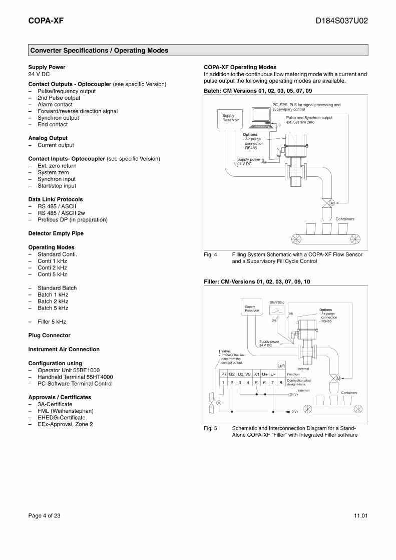
COPA-XF Operating ModesIn addition to the continuous flow metering mode with a current and pulse output the following operating modes are available.
Batch: CM Versions 01, 02, 03, 05, 07, 09
Filler: CM-Versions 01, 02, 03, 07, 09, 10
M
Containers
Options- Air purgeconnection
- RS485
Supply power24 V DC
Pulse and Synchron outputext. System zero
PC, SPS, PLS for signal processing andsupervisory control
2
3
SupplyReservoir
Fig. 4 Filling System Schematic with a COPA-XF Flow Sensor and a Supervisory Fill Cycle Control
1
P7
2
G2
3
Ux
4
V8
5
X1
6
U+
7
U-
8
Luft
M
M
internal
Function
Connection plugdesignations
external24 V+
0 V+
Containers
Options- Air purge
connection- RS485
Supply power24 V DC
2/6
1/6
SupplyReservoir
Start/Stop
Valve:Process the limitdata from thecontact output.
Fig. 5 Schematic and Interconnection Diagram for a Stand-Alone COPA-XF “Filler” with Integrated Filler software
Page 4 of 23 11.01

COPA-XF D184S037U02
Flowmeter Size Table, Flow Ranges, Flowrate Nomograph
Flowmeter Sizes, Pressure Ratings and Flow Ranges (Weld Stubs)
1) Values for other process connections see Page 3
Effective Flow Velocities, Various Process Connections, PFA
Flowrate NomographThe volume flowrate is a function of the flow velocity and the size of the flowmeter primary. The Flowrate Nomograph (Fig. 6) shows the flow ranges associated with each flowmeter size and which flowmeter sizes are suitable for a specific flowrate.
Example:Flowrate = 120 l/min (maximum value = flow range end value). Suitable are flowmeter primary sizes DN 20 - 65 / 3/4” - 2-1/2”.
Meter SizeDN Inch
Std.Press. Rating
PN1)
Min. Flow RangeFlow Velocity.0 to 0.5 m/s
Max. Flow RangeFlow Velocity.0 to 10 m/s
3 1/104 5/326 1/4
404040
0 to 0.2 l/min0 to 0.4 l/min0 to 1 l/min
0 to 4 l/min0 to 8 l/min0 to 20 l/min
8 5/16 10 3/815 1/2
404040
0 to 1.5 l/min0 to 2.25 l/min0 to 5 l/min
0 to 30 l/min0 to 45 l/min0 to 100 l/min
20 3/425 132 1-1/4
404040
0 to 7.5 l/min0 to 10 l/min0 to 20 l/min
0 to 150 l/min0 to 200 l/min0 to 400 l/min
40 1-1/250 265 2-1/2
404040
0 to 30 l/min0 to 3 m3/h0 to 6 m3/h
0 to 600 l/min0 to 60 m3/h0 to 120 m3/h
80 3100 4
4040
0 to 9 m3/h0 to 12 m3/h
0 to 180 m3/h0 to 240 m3/h
Meter SizeDN Inch
Qmax DN [l/min] deff [mm] Q deff [l/min] Veff [m/s]
3 1/10 4 3 4.2 9.4
4 5/32 8 4 7.5 10.6
6 1/4 20 6 17.0 11.8
8 5/16 30 8 30.2 9.9
10 3/8 45 10 47.1 9.5
15 1/2 100 13 79.6 12.6
20 3/4 150 18 152.7 9.8
25 1 200 24 271.4 7.4
32 1-1/4 400 30 424.1 9.4
40 1-1/2 600 36 610.7 9.8
50 2 1000 47 1041.0 9.6
65 2-1/2 2000 62 1811.4 11.0
80 3 3000 74 2580.5 11.6
100 4 4000 96 4342.9 9.2
l/min m /h3
5
4
3
2
3
2
102
8
103
65
4
3
8
65
4
2
2
Exa
mpl
e
Vol
ume
Flo
wra
te
3
102
8
10
8
6
5
65
4
3
2
4
3
2
1
8
65
4
3
3
10
8
6
5
4
2
2
1
10-1
8
6
5
4
3
2
8
65
4
3
2-2
10
m/s0.60.5 0.8 1 2 3 4 5 6 8 10
10-1
8
6
5
4
3
2
-210
8
6
5
4
3
10
8
6
5
4
3
2
1
8
65
4
3
2
8
6
5
4
3
2
l/h
DN 100
DN 80
DN 65
DN 50
DN 40
DN 32
DN 25
DN 20
DN 15
DN 10
DN 6
DN 8
DN 4
DN 3
Fig. 6 Flowrate Nomograph DN 3 to DN 100 / 1/10” to 4”
Page 5 of 23 11.01

COPA-XF D184S037U02
Installation Requirements, Flowmeter Primary
Up-/Downstream Straight Pipe SectionsThe operating principle is independent of flow profile as long as standing eddies are do not extend into the metering section (e.g. after space bends, tangential entries or partially open valves or gates). Under such conditions measures must be taken to condi-tion the flow profile.
Straight sections with the same inside diameter as the inlet diam-eter of the flowmeter primary should be installed up- and down-stream. The length upstream of the flowmeter should be at least 10 times the diameter of the flowmeter primary and downstream at least 5 times.
Experience has shown that in most instances straight sections with a length of 3xD upstream and 2xD downstream suffice.
Flowmeter Primary InstallationWhen installing the flowmeter primary the flow direction should be taken into account (flow is into the electrical plug connector) be-cause it is preferable to operate the primary in the forward flow di-rection. It is possible to change the direction indication from forward to reverse in the software. In vertical installations the flow-meter should be installed so that the electrical plug connector points downward. The flowmeter primary must be installed is a such a manner that the meter is always filled with fluid. Valves or other shut off devices should be installed downstream from the flowmeter primary so that the meter cannot drain.
GroundingGrounding is essential for safety considerations and to assure trou-ble free operation of the electromagnetic flowmeter primary. The ground screw on the flowmeter primary is to be connected to a ground for operating reasons. An additional ground to the connec-tion terminals is not required.
For plastic pipelines or pipes lined with an insulating material the ground is made using a grounding plate or grounding electrodes (only required for Wafer Design and PVC solvent weld coupling). When stray currents exist in the pipeline installation of grounding plates up- and downstream of the flowmeter primary is recom-mended.
Connection Cables
In the vicinity of the installation site appropriate suppression mea-sures should be employed, protection diodes, varistors or RC-com-binations, at valves and circuit protectors (VDE 0580).
!Note:The instrument satisfies the requirements of the EMC-Guide-line and the NAMUR-Recommendations NE 21 3/93 “Electro-magnetic Resistance of Equipment in the Process Industries and Laboratories”.
!Note:A water trap should be installed in the cables to the flowmeter primary.
Output SignalAn electronic frequency counter, SPC, PC or Process Control Sys-tem can be connected to the flowrate proportional scaled pulse or the frequency output. Therefore it is possible to integrate the flow-meter system into a batch or fill system as well as into continuous flow processes.
The processing of the pulse output for batch and fill processes must be accomplished in peripheral instrumentation. This includes controlling the system, integrating the flow for actuation of the valves when the fill quantity is reached, measurement of the over-run flow, calculation of the overrun correction and a check of the batch quantity for over- and/or underfills. A low flow cutoff of ap-prox. 1% flowrate can be turned on when required. Alternately, the integrated batch software for a single stage batch cycle can be uti-lized.
There is also a 0/4 - 20 mA current output available in the operating modes “Conti”.
Electrode AxisIn horizontal installations assure that neither of the two electrodes is positioned at the highest point in the system. Gas bubbles which may be present could interrupt the electrical connection between the electrodes and the fluid. The ideal EMF installation is in a ver-tical pipeline. Fig. 7 shows the two preferred installations.
!Warning:The flowmeter primary should not be installed in the vicinity of strong electromagnetic fields. We recommend that shielded connection cables be used. It is advantageous to route the cables in grounded metallic conduits in which a number of cables of the same type can be run together.Excess cable should not be coiled.
Vertical Installation
Electrode Axis
Fig. 7 Electrode Axis
Page 6 of 23 11.01
COPA-XF D184S037U02
Installation Requirements, Flowmeter Primary
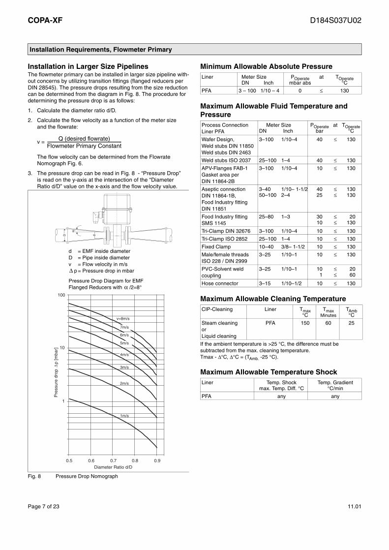
Installation in Larger Size PipelinesThe flowmeter primary can be installed in larger size pipeline with-out concerns by utilizing transition fittings (flanged reducers per DIN 28545). The pressure drops resulting from the size reduction can be determined from the diagram in Fig. 8. The procedure for determining the pressure drop is as follows:
1. Calculate the diameter ratio d/D.
2. Calculate the flow velocity as a function of the meter sizeand the flowrate:
v =
The flow velocity can be determined from the Flowrate Nomograph Fig. 6.
3. The pressure drop can be read in Fig. 8 - “Pressure Drop”is read on the y-axis at the intersection of the “Diameter Ratio d/D” value on the x-axis and the flow velocity value.
Minimum Allowable Absolute Pressure
Maximum Allowable Fluid Temperature and Pressure
Maximum Allowable Cleaning Temperature
If the ambient temperature is >25 °C, the difference must be subtracted from the max. cleaning temperature.Tmax - ∆°C, ∆°C = (TAmb. -25 °C).
Maximum Allowable Temperature Shock
Q (desired flowrate)Flowmeter Primary Constant----------------------------------------------------------------------------
10
1
0.5 0.6 0.7 0.8 0.9
Diameter Ratio d/D
v=8m/s
7m/s
6m/s
5m/s
4m/s
3m/s
2m/s
1m/s
100
Pre
ssur
e dr
op
p [m
bar]
D d
8°
d = EMF inside diameterD = Pipe inside diameterv = Flow velocity in m/s
p = Pressure drop in mbar∆
Pressure Drop Diagram for EMFFlanged Reducers with /2=8°α
Fig. 8 Pressure Drop Nomograph
Liner Meter SizeDN Inch
POperatembar abs
at TOperate°C
PFA 3 – 100 1/10 – 4 0 ≤ 130
Process ConnectionLiner PFA
Meter SizeDN Inch
POperatebar
at TOperate°C
Wafer Design,Weld stubs DIN 11850Weld stubs DIN 2463
3–100 1/10–4 40 ≤ 130
Weld stubs ISO 2037 25–100 1–4 40 ≤ 130
APV-Flanges FAB-1Gasket area perDIN 11864-2B
3–100 1/10–4 10 ≤ 130
Aseptic connectionDIN 11864-1B,Food Industry fittingDIN 11851
3–40 1/10– 1-1/250–100 2–4
4025
≤≤
130130
Food Industry fittingSMS 1145
25–80 1–3 3010
≤≤
20130
Tri-Clamp DIN 32676 3–100 1/10–4 10 ≤ 130
Tri-Clamp ISO 2852 25–100 1–4 10 ≤ 130
Fixed Clamp 10–40 3/8– 1-1/2 10 ≤ 130
Male/female threadsISO 228 / DIN 2999
3–25 1/10–1 10 ≤ 130
PVC-Solvent weld coupling
3–25 1/10–1 101
≤≤
2060
Hose connector 3–15 1/10–1/2 10 ≤ 130
CIP-Cleaning Liner Tmax°C
TmaxMinutes
TAmb°C
Steam cleaningorLiquid cleaning
PFA 150 60 25
Liner Temp. Shockmax. Temp. Diff. °C
Temp. Gradient°C/min
PFA any any
Page 7 of 23 11.01

COPA-XF D184S037U02
Ambient Requirements, Flowmeter Primary Specifications
Ambient Requirements-20 °C to +60 °C
Fluid Temperature-25 °C to +130 °C, CIP-Cleaning capable, see Temperature Diagram and Max. Allowable Cleaning Temperature.
Maximum allowable ambient temperature as a function of the fluid temperature for stainless steel process connections and a Wafer Design flowmeter primary.
Storage Temperature-25 °C to +70 °C
Flowmeter Primary SpecificationsMaterials
Process Connection Materials
Gasket Materials, Electrical Connector,Weight and Design
Supply PowerFrom converter
WeightSee Dimensions Pages 9 – 13
DesignFlowmeter primary with integrated µP-ConverterFlowmeter primary and converter housing made of stainless steel No. 1.4301/304
Process Connections DN 3 – 100 / 1/10” – 4”See Page 3 and Pages 9 – 13
Protection ClassStandard IP 67, option tropicalized
Max. Pipeline Vibration15 m/s2 (1.5 g) at f = 10 – 150 Hz
Instrument Air Connection, OptionG 1/10”-threads for purging the housing and plug connectorMax. 0.5 bar
Liner Electrode Material Electrode Design
Material Standard Others Standard Others
PFA Hast.-C4(1.4539 for pipe fittings & Tri-Clamp)
Hast.-B21.45391.4571/316TiTantalum, Titanium,Platinum-Iridium
Flat head Pointed head
(≥DN10-3/8”)
0
60
-20
-25 135FluidTemp. °C
Ambient Temperature °C
50
25
Fig. 9 Temperature Diagram
Standard OptionAPV-Flanges FAB-1 SS 1.4404/316L –
Wafer Design None
Weld stubs SS 1.4301/304 SS 1.4404/316L
Food Industry fitting DIN 11851 SS 1.4301/304 SS 1.4404/316L
Aseptic connection DIN 11864-1B SS 1.4404/316L –
Tri-Clamp DIN 32676 SS 1.4301/304 SS 1.4404/316L
Fixed Clamp SS 1.4301/304 SS 1.4404/316L
Tri-Clamp ISO 2852 SS 1.4301/304 SS 1.4404/316L
Food Industry fitting SMS 1145 SS 1.4301/304 SS 1.4404/316L
Male/female threads SS 1.4301/304 SS 1.4404/316L
Hose connector SS 1.4301/304 SS 1.4404/316L
PVC-solvent weld coupling PVC –
Process Connection Material Gasket Material
Wafer Design, None
Weld stubs, Flanges,Food Industry fittingAseptic connectionTri-ClampFixed ClampMale/female threads,Hose connector,PVC-solvent weld coupling
EPDM (Ethylene-Propylene) std. with FDA-Approval
Silicone with FDA-Approval (option)
Flat housing gasket Silicone
Page 8 of 23 11.01

COPA-XF D184S037U02
Dimensions: Flowmeter Primary, DN 3 - DN 100/1/10“ to 4“, Wafer Design, PFA
ISO Projection Method E
All dim´s in mm
155
120
52
G EF
AA*L
Di
∅
D∅
C∅
min
. 60
76
DN 3 - DN 8
Di
∅
13.6
∅
Air connectionG 1/8" (Option)
155120
52
G
EF
A*L
Di
∅
C∅
D∅
min
. 60
76Air connectionG 1/8" (Option)
DN 3 – DN 401/10” – 1-1/2”
DN 50 – DN 1002” – 4”
1) Installation length with 2 grounding plates L + 3 mm
Meter SizeDN Inch
PN A* A C D Di E F G L1) Weightapprox. kg
3 1/104 5/326 1/48 5/16
10 3/815 1/2 10–40
CL 150/CL 300
64 37 42 45
3468
1013
99 62 242 68 2.0
20 3/4 74 42 50 54 18 103 66 250 78 2.0
25 1 86 54 59 63 24 110 73 264 90 2.5
32 1-1/4 94 62 69 73 30 115 78 274 98 2.5
40 1-1/2 99 67 77 82 36 119 82 282 103 3.5
50 2 112 – 95 100 47 127 50 258 117 4.0
65 2-1/2 99 – 111 116 62 141 58 280 103 5.0
80 3 99 – 128 133 74 147 66.5 295 103 6.5
100 4 129 – 155 160 96 167 80 328 133 9.0
∅ ∅ ∅
Fig. 10 Dimensions, Model DF23, DN 3 - DN 100 / 1/10” - 4”, Wafer Design
Page 9 of 23 11.01

COPA-XF D184S037U02
Dimensions: Flowmeter Primary, Various Process Connections, PFA
3
LPipe
min
.60
76
D
Air connectionG 1/8" (Option)
A
F
G E52
155120
n
n
3
155
120
G
EF
A
D∅
min
. 60
76
Air connectionG 1/8" (Option)
DN 50 / 2” DN 65 to 100 / 2 1/2” - 4”
DN 3 – DN 401/10” – 1-1/2”
DN 50 – DN 1002” – 4”
Installation length with process connections see Pages 11 to 131) Plus process connection weight see Pages 11 to 13
Meter SizeDN Inch
A E F G D LPipe n Weightapprox. kg1)
3–10 1/10–3/8 37 99 62 242 44 85 – 2.0
15 1/2 37 99 62 242 44 85 – 2.0
20 3/4 42 103 66 250 63 90 – 2.0
25 1 54 110 73 264 63 105 – 2.5
32 1-1.4 62 115 78 264 78 120 – 2.5
40 1-1/2 67 119 82 282 78 125 – 3.5
50 2 128 127 50 258 100 – 4 5.0
65 2-1/2 114 141 58 280 116 – 6 5.5
80 3 114 147 66.5 295 133 – 6 7.0
100 4 144 167 80 328 160 – 6 9.0
ISO Projection Method E
All dim´s in mm
Fig. 11 Dimensions, Model DF23, DN 3 to DN 100 / 1/10” to 5”, Various Process Connections, Basic Dimensions Apply to All Process Connections
Page 10 of 23 11.01

COPA-XF D184S037U02
Dimensions: Adapters for Various Process Connections
Meter Size Weld Stubs
ISO 2037 DIN 11850 DIN 2463
DN Inch Di Da L Wgt./kg1) Di Da L Wgt./kg1) Di Da L Wgt./kg1)
3-10 1/10-3/8 – – – – 10.0 13.0 127 0.4 10.3 13.5 127 0.4
15 1/2 – – – – 16.0 19.0 127 0.4 18.1 21.3 127 0.4
20 3/4 – – – – 20.0 23.0 132 0.7 23.7 26.9 132 0.7
25 1 22.6 25.0 149 0.7 26.0 29.0 149 0.7 25 28 149 0.7
32 1-1/4 31.3 33.7 166 1.0 32.0 34.0 166 1.0 32 35 166 1.0
40 1-1/2 35.6 38.0 171 1.0 38.0 41.0 171 1.0 36.8 40 171 1.0
50 2 48.6 51.0 173 1.0 50.0 54.0 173 1.0 49 52 173 1.0
65 2-1/2 60.3 63.5 165 1.4 66.0 70.0 165 1.4 66 70 165 1.4
80 3 72.9 76.1 169 2.0 81.0 85.0 169 2.0 81 85 169 2.0
100 4 97.6 101.6 199 2.6 100.0 104.0 199 2.6 100 104 227 3.0
∅ ∅ ∅ ∅ ∅ ∅
1) Weight per pair
Food Industry FittingDIN 11851
Aseptic ConnectionDIN 11864-1 (Form B)
DN Inch Rd. Thds. L Wgt./kg1) Rd. Thds. L Wgt./kg1)
3-10 1/10-3/8 28 x 1/10” 169 0.5 34 x 1/10” 161 0.5
15 1/2 34 x 1/10” 169 0.5 44 x 1/6” 161 0.5
20 3/4 44 x 1/6” 180 0.9 44 x 1/6” 170 0.9
25 1 52 x 1/6” 207 0.9 52 x 1/6” 197 0.9
32 1-1/4 58 x 1/6” 230 1.4 58 x 1/6” 220 1.4
40 1-1/2 65 x 1/6” 237 1.4 65 x 1/6” 227 1.4
50 2 78 x 1/6” 243 1.4 78 x 1/6” 233 1.4
65 2-1/2 95 x 1/6” 245 2.2 95 x 1/6” 233 2.2
80 3 110 x 1/4” 259 3.2 110 x 1/4” 245 3.2
100 4 130 x 1/4” 307 4.4 130 x 1/4” 291 4.4
Meter Size Food Industry FittingSMS 1145
DN Inch Rd. Thds. L Wgt./kg1)
3-10 1/10-3/8 – – –
15 1/2 – – –
20 3/4 – – –
25 1 40 x 1/6” 180 0.7
32 1-1/4 48 x 1/6” 201 1.0
40 1-1/2 60 x 1/6” 212 1.0
50 2 70 x 1/6” 214 1.0
65 2-1/2 85 x 1/6” 226 1.4
80 3 98 x 1/6” 230 2.0
100 4 132 x 1/6” 282 3.0
L
Da
∅∅D
i
Weld Stubs perDIN 11850 or ISO 2037 or DIN 2463
L
Food Industry Fitting DIN 11851 orAseptic Connection DIN 11864-1B
L
Rd-
Gew
.
Pipe Fitting SMS 1145
ISO Projection Method E
All dim´s in mm
Fig. 12 Dimensions DN 3 to 100 / 1/10” to 4”, Adapters for Various Process Connections
Page 11 of 23 11.01

COPA-XF D184S037U02
Dimensions: Adapters for Various Process Connections
45°
22,5°
45°n
n
n
APV-Flange
Bolt Circle for APV-FlangeDN 3 - 65 / 1/10” - 2 1/2” (4 holes)
DN 80 - 100 / 3” - 4” (8 holes)
Bolt Circle for ABB-AdapterDN 50 / 2” (4 holes)
DN 65 - 100 / 2 1/2” - 4” (6 holes)
APV-Flange
ABB-Adapter
ABB-Adapter
n
Meter Size Tri-Clamp
DIN 32676 ISO 2852
DN Inch Di L Wgt./kg1) Di L Wgt./kg1)
3-10 1/10-3/8 10.0 163 0.5 – – –
15 1/2 16.0 163 0.5 – – –
20 3/4 20.0 168 0.7 – – –
25 1 26.0 192 0.8 22.6 192 0.8
32 1-1/4 32.0 209 1.5 – – –
40 1-1/2 38.0 214 1.4 35.6 214 1.4
50 2 50.0 216 1.2 48.6 216 1.2
65 2-1/2 66.0 221 1.6 60.3 221 1.6
80 3 81.0 225 2.4 72.9 225 2.4
100 4 100.0 255 3.1 97.6 225 3.1
∅ ∅
Fixed Clamp
DN Inch Di Dm Da L Wgt./kg2)
10 3/8 10 30 50.5 85 2.5
15 1/2 13 30 50.5 85 2.5
20 3/4 18 40 64 90 2.7
25 1 24 40 64 105 3.3
32 1-1/4 30 55 91 120 4.0
40 1-1/2 36 55 91 125 4.9
∅ ∅ ∅
Meter Size APV-Flange FAB-1Gasket Area per DIN 11864-2B
DN Inch ∅APV-Fl. FAB-1
Wgt.kg1)
n(APV)
n(F&P)
3-10 1/10-3/8 183 0.9 4 –
15 1/2 183 1.0 4 –
20 3/4 188 1.3 4 –
25 1 207 1.6 4 –
40 1-1/2 229 1.8 4 –
50 2 231 2.2 4 4
65 2-1/2 223 3.0 4 6
80 3 227 4.0 8 6
100 4 257 5.0 8 6
L
∅D
i
Tri-Clamp perDIN 32676 or ISO 2852
L
Di
Dm
Da
Fixed Clamp
1) Weight per pair2) Weight of basic meter plus Fixed Clamp (1 pipe section)
ISO Projection Method E
All dim´s in mm
Fig. 13 Dimensions, DN 3 to DN 100 / 1/10” to 4” , Adapters for Various Process Connections
Page 12 of 23 11.01
COPA-XF D184S037U02
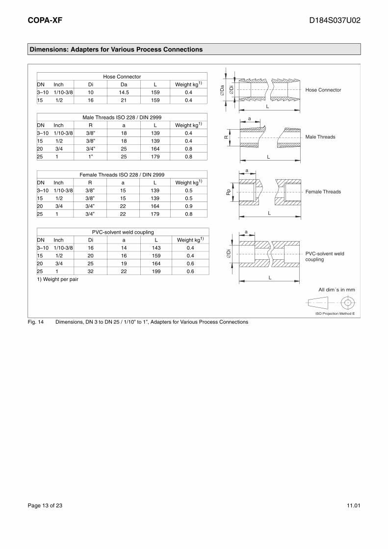
Dimensions: Adapters for Various Process Connections
Hose Connector
DN Inch Di Da L Weight kg1)
3–10 1/10-3/8 10 14.5 159 0.4
15 1/2 16 21 159 0.4
Male Threads ISO 228 / DIN 2999
DN Inch R a L Weight kg1)
3–10 1/10-3/8 3/8” 18 139 0.4
15 1/2 3/8” 18 139 0.4
20 3/4 3/4” 25 164 0.8
25 1 1” 25 179 0.8
Female Threads ISO 228 / DIN 2999
DN Inch R a L Weight kg1)
3–10 1/10-3/8 3/8” 15 139 0.5
15 1/2 3/8” 15 139 0.5
20 3/4 3/4” 22 164 0.9
25 1 3/4” 22 179 0.8
1) Weight per pair
PVC-solvent weld coupling
DN Inch Di a L Weight kg1)
3–10 1/10-3/8 16 14 143 0.4
15 1/2 20 16 159 0.4
20 3/4 25 19 164 0.6
25 1 32 22 199 0.6
L
Hose Connector
Male Threads
Female Threads
PVC-solvent weldcoupling
a
L
a
RD
a∅ ∅
Di
∅D
i
L
L
aR
p
ISO Projection Method E
All dim´s in mm
Fig. 14 Dimensions, DN 3 to DN 25 / 1/10” to 1”, Adapters for Various Process Connections
Page 13 of 23 11.01

COPA-XF D184S037U02
Specifications: Converter
Flow RangeSelectable between 0.05 – 1* Qmax DN
Reproducibility0.2 % for TBatch ≥ 4 s0.4 % for 2 s ≤ TBatch ≤ 4 s
Flow DirectionForward/reverse
Minimum Conductivity≥ 5 µS/cm, ≥ 20 µS/cm DN 3-8/1’8”-5/16”, ≥ 20µS/cm VE-Water
Electrical ConnectionsPlug, option with 5 m attached cable Type Tronic flexible per DIN 47100 LIYY 8x0.5 mm2 outside 7.8 mm Item No. 18091 Helukabel
Supply Power24 V DC, allowable voltage variations +/-30 %Ripple ≤ 5 %
PowerDN 3-100/1/10”-4” ≤ 6 W (flowmeter primary incl. converter)
Magnetic Field Excitation12.5 Hz / 25 Hz
Ambient Temperature-20 °C to +60 °C (see Temperature Diagram Fig. 9 )
Response Time for Pulse/Frequency Output
Min. response time T0.99 =
Min. batch time TBatch =2 s
Low Flow CutoffSelectable between 0 - 10 % of max.
Output Signals– Scaled Pulse output, passive, optocoupler
0 ≤ UCEL ≤ 2 V; 16 V ≤ UCEH ≤ 30 V2 mA ≤ ICEL ≤ 220 mA; 0.2 mA ≤ ICEH ≤ 2 mASelection range: 0.001 – 1000 pulse per selected unitPulse width: 100 s – 2000 msfmax : 5 kHzPINS 3 and 4
– 2nd Pulse output with fixed scaling factor 1:20passive, optocoupler0 ≤ UCEL ≤ 2 V; 16 V ≤ UCEH ≤ 30 V2 mA ≤ ICEL ≤ 220 mA; 0.2 mA ≤ ICEH ≤ 2 mAPINS 2 and 3
– Flowrate proportional pulse output1.2 or 5 kHz for flowrate = 100 %passive, optocoupler0 ≤ UCEL ≤ 2 V; 16 V ≤ UCEH ≤ 30 V2 mA ≤ ICEL ≤ 220 mA; 0.2 mA ≤ ICEH ≤ 2 mAPINS 3 and 4
– Scaled pulse output, active16 V ≤ U < 30 V2 mA ≤ I ≤ 150 mA for fmax ≤ 4 Hz, on/off ratio = ≤
Pulse width t ≤ 50 ms t16V ≤ 25 ms
2 mA ≤ I ≤ 20 mA for fmax ≤ 5 kHzPINS 2 and 4
– Current output (selectable)Load ≤ 600 for 0/4–20 mA, 0–10– 20 mA, 4–12–20 mALoad ≤ 1200 for 0/2–10 mALoad ≤ 2400 for 0–5 mAPINS 5 and 8
– Data Link RS 485Max. cable length 1200 mMax. number: 32 Instruments parallelMax. baudrate: 9600 BaudCommunication-Protocol: ASCII 2W“Communication Plug” PINS 3 and 4Connection for Handheld Terminal or SPC, PCS, PC
– Handheld Terminal 55HT4000Plug into “Communication Socket”Supply power 24 V DC over PINS 1 and 2
– Contact output (function dependent on Operating Mode)Alarm, forward/reverse, Synchron or end contactpassive, optocoupler0 ≤ UCEL ≤ 2 V; 16 V ≤ UCEH ≤ 30 V0 mA ≤ ICEH ≤ 0.2 mA, 2 mA ≤ ICEL ≤ 220 mAPINS 1 and 3
– Contact input (function dependent on Operating Mode)Ext. zero return, system zero, Synchron input,Start/Stop inputOptocoupler16 V ≤ U ≤ 30 V, Ri = 2 kOhmPINS 5 and 2
∅
1Magnetic Field Excitation------------------------------------------------------------------
µ
ton
toff------- 1
4---
ΩΩΩ
Page 14 of 23 11.01

COPA-XF D184S037U02
Specifications: Converter
Overview of Available Converter Versions
Symbols:x Factory default settingo SelectableA, K etc.Only available for specific operating modes.
Design Level B
VersionReplace-ment forDesign
A01 02 03 04 05 06 07 08 09 10
HardwareContact output x x x x x x x x x xContact input x x x x xPulse passive x x x x x x x x xPulse active x2nd pulse passive xCurrent output x x x xRS 485 x xProfibus DP x xAir connection x x
MenusOperating Mode
Standard Conti.K x x x x x x x x x xStandard BatchB o o o o o o o oBatch 1 kHzB1 o o o o o o o oBatch 2 kHzB2 o o o o o o o oBatch 5 kHzB5 o o o o o o o oFiller 5 kHzA o o o o o o o oConti 1 kHzK1 o o o o o o o o o oConti 2 kHzK2 o o o o o o o o o oConti 5 kHzK5 o o o o o o o o o o
Contact outputAlarm x x x x x x x x x xFwd/Rev o o o o o o o o o oSynchron o o o o o o o oEnd contact A A A A A A A A
Contact inputExt. zero return x x x x xSystem zero o o o o oSynchronStart A A A A A
Current output KK1K2K5
KK1K2K5
KK1K2K5
KK1K2K5
Data linkASCII x xASCII2w o oProfibus DP o o
Detector Empty Pipe K K K K K K K o K
Plug Type PIN Designations for the Standard Plug COPA-XF Designations for Communication PlugVersion PIN 1 PIN 2 PIN 3 PIN 4 PIN 5 PIN 6 PIN 7 PIN 8 PIN 1 PIN 2 PIN 3 PIN 4
1 P7 G2 Ux V8 X1 U+ U- ../.. ../.. ../.. ../.. ../..2 P7 G2 Ux V8 X1 U+ U- ../.. + 25 V B A3 P7 G2 Ux V8 X1 U+ U- Air ../.. ../.. ../.. ../..5 P7 Vc Ux V8 + U+ U- – ../.. ../.. ../.. ../..7 P7 X1 Ux V8 + U+ U- – ../.. ../.. ../.. ../..8 P7 V9 Ux V8 + U+ U- – ../.. ../.. ../.. ../..
9 (N-switched) P7 X1 G2 (E9) C9 ../.. U+ U- ../.. ../.. ../.. ../.. ../..10 P7 ../.. Ux V8 + U+ U- – + 25 V B A
20 P7 ../.. Ux V8 + U+ U- – + 25 V B A21 P7 G2 Ux V8 X1 U+ U- ../.. ../.. ../.. ../.. ../..22 P7 Vc Ux V8 + U+ U- – ../.. ../.. ../.. ../..23 P7 G2 Ux V8 X1 U+ U- Air ../.. ../.. ../.. ../..
⊥
⊥
⊥
Page 15 of 23 11.01

COPA-XF D184S037U02
Interconnection Diagram COPA-XF, P-Switched, Model DF23, Design Level B
Design P-Conducting(Pulse output, current output, contact input, contact output, supply power, external air supply, data link, supply power Handheld Terminal)
a) Scaled Pulse output, passive optocoupler, pulse width selectable from 0.100 ms to 2000 msfmax 5 kHz is a function of the selections in the submenu “Operating Mode”,0 V ≤ UCEL ≤ 2 V, 16 V ≤ UCEH ≤ 30 V2 mA ≤ ICEL ≤ 220 mA; 0.2 mA ≤ ICEH ≤ 2 mAConnection plug PINS 3, 4; Function Ux, V8
b) 2nd pulse output, passive optocoupler, with fixed scaling factor 1:20Specifications see 1)Connection plug PINS 2, 3; Function Vc, Ux
c) Scaled Pulse output, active 16 V ≤ U < 30 V2 mA ≤ I ≤ 150 mA for fmax ≤ 4 Hz, on/off ratio = ≤
Pulse width t ≤ 50 ms/ t16V ≤ 25 ms2 mA ≤ I ≤ 20 mA for fmax ≤ 5 kHz, Connection plug PINS 2 and 4; Function V8, V9
d) Current output (selectable)Load ≤ 600 for 0/4–20 mA, 0–10– 20 mA, 4–12–20 mALoad ≤ 1200 for 0/2–10 mA; Load ≤ 2400 for 0–5 mAConnection plug PINS 5 and 8; Function +, –
e) Contact output, selection is a function of the selections in the submenu “Operating Mode”,Synchron-Signal (output signal synchronized to excitation), F/R direction signal or end contact,passive optocoupler, 0 V ≤ UCEL 2 V, 16 V ≤ UCEH ≤ 30 V / 0 mA ≤ ICEH ≤ 0.2 mA, 2 mA ≤ ICEL ≤ 220 mAConnection plug PINS 1, 3; Function P7, Ux
f) Contact input, selection is a function of the selections in the submenu “Operating Mode”,Start/Stop, external totalizer reset, system zero1), no function, passive optocoupler, 16 V ≤ U ≤ 30 V, Ri = 2 kOhmConnection plug PINS 2, 5; Function G2, X1
g) Supply power 24 V DC ± 30 % ripple ≤ 5 %Connection plug PINS 6, 7; Function U+, U-
h) Option external air supply for converter and plug, for housing with an instr. air connection. PIN 8 in the socket is not available.Connection plug PIN 8; Function plug air purge
i) Data link RS 485, 2-Wire, Vpp = 5 V, input resistance ≥ 12 kOhmmax. cable length ≤ 1200 m, shielded cable with twisted pairs required,Baudrate 110 - 9600 Baud, max. 32 instruments in parallel,Communication plug PINS 3, 4; Function B, A (RS 485)
j) Connection for Handheld Terminal 55HT4000Communication plug PINS 3, 4; Function B, A (RS 485);Communication plug PINS 1, 2; Function , +25 V (Supply power from CM for 55HT4000)
1) If a system zero adjust is initiated, the flow of fluid must be at an absolute zero, the meter tube must be guaranteed to be completely full.
Note: To maintain the EMC-Requirements the instrument must be connected to ground.When the housing is open the EMC-Protection is voided.
Connection Connection Plug Communication PlugPIN-No. 1 2 3 4 5 6 7 8 1 2 3 4
Legend Functions (PIN Designations) Functions (PIN Designations)a) Ux V8b) Vc Uxc) V9 V8d) + –e) P7 Uxf) G2 X1g) U+ U-h) Airi) B Aj) +25V B A⊥
ton
toff------- 1
4---
ΩΩ Ω
⊥
Fig. 15 Interconnection Diagram, P-Switched In-/Outputs with PIN-Designations for the Connection and Communication Plugs
Page 16 of 23 11.01

COPA-XF D184S037U02
Interconnection Diagram for Peripherals COPA-XF, Model DF23, P-Switched In-/Outputs/Data Link
Passive Passive
Version Overview P-/N-Conducting and SPS-Conformity
Pin 3(Ux)
Pin 4(V8)
externalinternal
Pulse Output optocoupler Pin 3 / Pin 4Contact Output optocoupler Pin 3 / Pin 1Contact Output for Synchron-SignalF/R Direction Signal, End ContactFunction software selectable
gray
yellow
white
RB* ≥ UCE
ICE-----------
Pin 1(P7)
RB*
RB*
–
–
24 V+
Supply Power (24 V DC)
24 V+
–
External Supply
Pin 6(L+)
Pin 7(L-)
red
blue
0/4 - 20 mA or0/2 - 10 mA0 - 5 mA0 - 10 - 20 mA4 - 12 - 20 mA
Current Output Pin 5 / Pin 8
PIN 5+
PIN 8–
externalinternal
Operation with 55HT4000,Max. 4 Instruments
Data Link RS 485,Max. 32 Instruments
Addr. “0” Addr. “0”
Contact input Optocoupler Pin 5 / Pin 2Contact Input for Start/Stop, System Zero,No Function Function software selectable
externalinternal
Pin 5(X1)
Pin 2(G2)
24 V+
–
pink
green
Fig. 16 Interconnection Examples for Peripherals, P-Switched In-/Outputs/Data Link
Version: 9N-Switched
Version: 1, 2, 3, 21, 23P-Switched SPS conf.
Version: 5, 22P-Switched SPS conf.
Version: 8 P-SwitchedSPS conf. Version: 10, 20
P-SwitchedSPS conf.
Version: 7P-Switched
Pulse Out-
Input
Contact Out-
X1 (2)
G2 (3)
C9 (4)
P7 (1)
Pulse Out-
Input
Contact Out-
X1 (5)
G2 (2)
UX (3)
P7 (1)
V8 (4)
Pulse Output
Contact Output
V8 (4)
P7 (1)
Vc (2)
UX (3)
2nd Pulse Out.
Current Output– (8)+ (5)active
Current Output– (8)+ (5)
Pulse OutputV8 (4)V9 (2)
Contact OutputUX (3)
P7 (1)
active
active
– (8)+ (5)
V8 (4)
UX (3)
P7 (1)
Pulse Output
Contact Output
Current Output
active
V8 (4)
– (8)+ (5)
P7 (1)
UX (3)
X1 (2)
Input
Pulse Output
Contact Output
Current Output
active
Fig. 17 Version Overview P-/N-switched and SPS-Conformity
Page 17 of 23 11.01

COPA-XF D184S037U02
Interconnection Diagram COPA-XF, N-Switched, Version 9, Model DF23, Design Level B
Interconnection Examples for Peripherals, Version 9COPA-XF, Model DF23, N-Switched In-/Outputs
Design N-Switched(Pulse output, contact input, contact output, supply power, external air supply)
a) Scaled Pulse output, passive optocoupler, pulse width selectable from 0.100 ms to 2000 msfmax 5 kHz is a function of the selections in the submenu “Operating Mode”,0 V ≤ UCEL ≤ 2 V, 16 V ≤ UCEH ≤ 30 V0 mA ≤ ICEH ≤ 0.2 mA, 2 mA ≤ ICEL ≤ 220 mAConnection plug PIN 3, 4; Function G2, C9
e) Contact output, selection is a function of the selections in the submenu “Operating Mode”,Synchron-Signal (output signal synchronized to excitation), F/R direction signal or end contact,passive optocoupler, 0 V ≤ UCEL 2 V, 16 V ≤ UCEH ≤ 30 V / 0 mA ≤ ICEH ≤ 0.2 mA, 2 mA ≤ ICEL ≤ 220 mAConnection plug PIN 1, 3; Function P7, G2
f) Contact input, selection is a function of the selections in the submenu “Operating Mode”,Start/Stop, external totalizer reset, system zero1), no function, passive optocoupler, 16 V ≤ U ≤ 30 V, Ri = 2 kOhmConnection plug PIN 3, 5; Function G2, X1
g) Supply power 24 V DC ± 30 +, ripple 5 %Connection plug PIN 6, 7; Function +25 V,
1) If a system zero adjust is initiated, the flow of fluid must be at an absolute zero, the meter tube must be guaranteed to be completely full.
Note: To maintain the EMC-Requirements the instrument must be connected to ground.When the housing is open the EMC-Protection is voided.
Designations Connection PlugPIN-No. 1 2 3 4 5 6 7 8
Legend Functions (PIN Designations)a) G2 C9e) P7 G2f) X1 G2g) +25 V ⊥
⊥
Fig. 18 Interconnection Diagram N-Switched In-/Outputs with Pin Designations for Connection Plug
Contact input for external totalizer resetStart/Stop, System zero,Function software selectable
PIN 2(X1)
PIN 3(G2)
externalinternal
24 V+
–
Pulse Output Optocoupler
externalinternal
RB*PIN 4(C9)
PIN 3(G2)
24 V+
–
Contact output for Synchron-SignalF/R Direction Signal, End contactFunction software selectable
externalinternal
RB*PIN 1(P7)
PIN 3(G2)
24 V+
–
RB* ≥ UCE
ICE-----------
Control of a Magnetic Valve fromSynchronous Signal
To realize improved reproducibility for shortbatches, it is advantageous to synchronize the opening of the magnetic valve to the switchingcycle of the XF-Metering system.
The magnetic valve control is synchronizedto the positive converter switching point.
open/closed
Magnetic valve: closed/open
Start signal
Fig. 19 Interconnection Examples for Peripherals, N-Switched In-/Outputs !Only for Version 09!
Page 18 of 23 11.01

COPA-XF D184S037U02
Interconnection Diagram COPA-XF, N-Switched/Plug w/ Cable, Model DF23, Design Level B
Plug Connections(Solder Side)1 white2 green3 gray4 yellow5 pink6 red7 blue8 brown
A B
Plug Connections(Solder Side)1 white2 brown3 green 4 yellow
C
Connection Plug (Supply Power, In-/Output) Communication Plug
Connection Plug Angled (A) or Straight (B) Design Communication Plug (C) Straight or Angled Design
Option:Plug with attached cable plug, PVC data cable, 5 mType Tronic flexible per DIN 47100, LIYY 8 x 0.5 mm2
Outside diameter 7.8 mm, Item No. 18091 HelukabelConnection Plug Designations with Attached Cable
Angled plug with 5 m cable: (ABB Part No. D677A342U01)Straight plug with 5 m cable: (ABB Part No. D677A342U02
Scaled pulse outputpassive, opto, (P-Conducting)
UxV8
Pin 3 (gray lead)Pin 4 (yellow lead)
2nd pulse output passive, opto, (P-Conducting)
UxVc
Pin 3 (gray lead)Pin 2 (green lead)
Scaled pulse outputactive 24 V DC
V8V9
Pin 4 (yellow lead)Pin 2 (green lead)
Current output0/4 - 20 mA
+–
Pin 5 (pink lead)Pin 8 (brown lead)
Contact outputpassive, opto, (P-Conducting)
UxP7
Pin 3 (gray lead)Pin 1 (white lead)
Contact inputpassive, opto, (P-Conducting)
X1G2
Pin 5 (pink lead)Pin 2 (green lead)
Supply power 24 V DC U+U-
Pin 6 (red lead)Pin 7 (blue lead)
No function or external air supply
Pin 8 (brown lead)
Option:Handheld Terminal 55HT4000 with 2.5 m cable and straight plug or with 10 m cable with angled plug (see Ordering No. 55HT4000)
Data linkRS 485, 2 wire
AB
Pin 4 (yellow lead)Pin 3 (green lead)
Supply power 24 V DCfor Handheld Terminal55HT4000 from CM
+25 VPin 1 (white lead)Pin 2 (brown lead)
⊥
Fig. 20 Interconnection Diagram, Supply Power, P-Switched In-/Outputs, Communication Option
Page 19 of 23 11.01

COPA-XF D184S037U02
Ordering Information: Electromagnetic Flowmeter Model DF23
OIn addition to the Ordering Number please supply the following information:Fluid, fluid operating temperature, operating pressure, pipeline construction (grounding plates)
1) Grounding electrodes from DN 3 / 1/10”
Compact Design COPA-XF DF23
Process ConnectionsWafer DesignWeld stubs DIN 11850Weld stubs DIN 2463Weld stubs ISO 2037 (DN25-100 / 1”-4”)Food Industry fittings DIN 11851Food Industry fittings SMS 1145 (DN25-100 / 1”-4”)Aseptic connection DIN 11864-1Tri-Clamp DIN 32676Tri-Clamp ISO 2852 (DN 25 - 100(except DN32 / 1-1/4”)Fixed Clamp (DN10-40/ 3/8”-1-1/2”)APV-Flange FAB-1, Gasket DIN 11864-2B(except DN32 / 1-1/4”)Hose connector (DN3-15 / 1/10”-1/2”)Male threads ISO 228/DIN 2999(DN3-25 / 1/10”-1”)Female threads ISO 228/DIN 2999(DN3-25 / 1/10”-1”)PVC-Solvent weld coupling(DN3-25 / 1/10”-1”)Without adapter (w/o union nut or bolts)
WRQPSDATUCLHEIGV
Liner MaterialPFA P
Flowmeter SizeDN 31/10”DN 45/32”DN 61/4”DN 83/16”DN 103/8”DN 151/2”DN 203/4”DN 251”DN 321-1/4”DN 401-1/2”DN 502”DN 652-1/2”DN 803”DN 1004”
030406081015202532405065801H
Signal Electrode Material/ Ground Electrode Material)
SS No. 1.4571/316Ti/ noneHastelloy C-4/ none (Standard)Titanium/ noneTantalum/ noneSS No. 1.4539/ none (for Food Industry applications)SS No. 1.4571/316TI/ withHastelloy C-4/ with (Standard)Titanium/ withTantalum/ withSS No. 1.4539/ with (for Food Industry applications)
SHMTFEOIQR
Pressure RatingStandard for APV-Flanges,Tri-Clamp, Fixed Clamp, Male/female threads,
PN 10Hose connector, PVC-Cement sleeve C
PN 16PN 25Only Wafer Design, Food Industry fittings,PN 40Aseptic connection and weld stubs
DEF
Process Connection MaterialNone(Only Wafer Design)SS No. 1.4404/316LSS No. 1.4301/304(Standard)PVC(Only PVC-Cement sleeve)
0467
Page 20 of 23 11.01

COPA-XF D184S037U02
Ordering Information: Electromagnetic Flowmeter Model DF23
2) Certificate for meter tube and weld stubs (if req’d: for other process connections)!! Note !! Not for PVC Process Connections
3) In-/Output Versions ≥ 20 are customer specific Versions5) For special applications, e.g. high grease content fluids
Compact Design COPA-XF DF23AccessoriesNoneIncl. flowmeter mounting element
AC
Temperature RangeStandard design <130 °C S
CertificatesNoneInspection Test Report per EN 10204 3.1B2)
AD
Protection ClassIP 67Tropicalized
24
Supply Power24 V DC H
External ConnectionsConnection Plug (angled),without air connection (standard)Connection Plug (straight)without air connectionConnection Plug (angled),without air connection, incl. 5 m cableConnection Plug (straight)without air connection, incl. 5 m cableConnection Plug (angled)plus communication socket and plugConnection Plug (straight)plus communication socket and plugConnection Plug (angled)incl. air connection
1234678
In-/Output (Versions) 3)(see External Connections)Contact output/pulse passive, opto/contact input (standard)(1/2, 3/4)Contact output/pulse passive, opto/contact input/RS 485 (2nd plug)(6/7)Contact output/pulse passive, opto/contact input/air connection(8)Contact output/pulse passive, opto/current output/2nd pulse passive(1/2, 3/4)Contact output/pulse passive, opto/contact input/current output(1/2, 3/4)Contact output/pulse active, opto/current output(1/2, 3/4)Contact output/pulse passive, opto/contact input (repl. for N-switched)(1/2, 3/4)Contact output/pulse passive, opto/current output/RS 485 (2nd plug)(6/7)
0102030507080910
ApplicationStandard 0
Instrument TagGermanEnglish
GE
Design Level BGasket MaterialEPDM with FDA-Approval(standard)Silicone with FDA-ApprovalNone(only Wafer Design)
ESO
Electrode DesignStandardPointed head 5)(from DN 10 / 3/8”)
12
Excitation Frequency12 1/2 Hz(DN 50 - 100 / 2” - 4”)25 Hz(DN 3 - 40 / 1/10” - 1-1/4”)
25
!Note:An Operator Unit 55BE1000 is required to configure the converter which requires that the housing cover be opened.WARNING! The EMC-Protection is limited when the housing cover is opened.
If the converter includes a data link, the converter can be configured using the Handheld Terminal 55HT4000 or a PCS-Systemor PC using the ASCII-Protocol without opening the housing cover.
Page 21 of 23 11.01

COPA-XF D184S037U02
Ordering Information: Operator Unit 55BE1000
Ordering Number 55BE1
DesdignWithout battery for lighting the displayIncluding 9 V battery for lighting the display
00A10A
Instrument TagGermanEnglishFrench
123
BedieneinheitOperator Unit
ENTER
DATA STEP C/CE
>V 49.9800 l/s>V 1349.00 m3
Data Entry for COnverterThe data is entered from the separate Operator Unit 55BE1000. The cover of the converter housing is unscrewed, the cable from the Operator Unit is plugged into the front plate of the converter. For illuminating the display a 9 V battery can be installed in the battery compartment. The battery can be or-dered with the unit. The converter data entry is described in the Instruction Bulletin for the flowmeter system.
Warning:The EMC-Protection is limited when the housing cover is opened.
Fig. 21 Operator Unit 55BE1000 for Converter Data Entry
Page 22 of 23 11.01

COPA-XF D184S037U02
Ordering Information: Handheld Terminal 55HT4000
Ordering Number 55HT4
Keypad LayoutStandard 1
Supply Power24 V AC/DC 1
Connection Cable with Plug2.5 m with straight plug, Handheld Terminal10 m with angled plug, for panel mounting
12
Design Level 0
Instrument TagGermanEnglish
12
Fig. 22 Handheld Terminal 55HT4000 for Converter Data Entry.Required is a COPA-XF Version which includes a RS 485 Data Link and a Communication Socket.
Page 23 of 23 11.01

Rights reserved to make technical changes.Printed in the Fed. Rep. of Germany
Certified per DIN EN ISO 9001Part No. D184S037U02 Rev. 01
ABB Automation Products GmbHDransfelder Str. 2D-37079 Göttingen, GermanyTel. 0551/90 5 - 0 Fax 0551/90 57 77http://www.abb.com


![User's AXF Manual Magnetic Flowmeter Integral Flowmeter ... · User's Manual Yo kogawa Electric Corporation AXF Magnetic Flowmeter Integral Flowmeter/ Remote Flowtube [Hardware Edition]](https://img.pdfslide.us/doc/110x75/5c40f15893f3c338c3289cbb/users-axf-manual-magnetic-flowmeter-integral-flowmeter-users-manual-yo.jpg)


![AXR Two-wire Magnetic Flowmeter Integral Flowmeter [Style:S2]](https://img.pdfslide.us/doc/110x75/62cb14e07ee31d38b74d3e5b/axr-two-wire-magnetic-flowmeter-integral-flowmeter-styles2.jpg)
![User's AXF Manual Magnetic Flowmeter Integral Flowmeter ... · Magnetic Flowmeter Integral Flowmeter/ Remote Flowtube [Hardware Edition] IM 01E20D01-01E IM 01E20D01-01E 7th Edition](https://img.pdfslide.us/doc/110x75/5e9c29fa54300501b21ae83a/users-axf-manual-magnetic-flowmeter-integral-flowmeter-magnetic-flowmeter-integral.jpg)