Embed Size (px)
Citation preview

D. Poljak & D. Čavka, Int. J. Comp. Meth. and Exp. Meas., Vol. 3, No. 3 (2015) 250–268
© 2015 WIT Press, www.witpress.comISSN: 2041-9031 (paper format), ISSN: 2041-904X (online), http://www.witpress.com/journalsDOI: 10.2495/CMEM-V3-N3-250-268
ELECTROMAGNETIC COMPATIBILITY ISSUES OF WIND TURBINE ANALYSIS AND DESIGN
D. POLJAK & D. ČAVKAMechanical Engineering and Naval Architecture, Faculty of Electrical Engineering, Mechanical Engineering and
Naval Architecture, University of Split, Croatia.
ABSTRACTThis article reviews numerical modeling methods for certain electromagnetic compatibility topics in wind turbine (WT) analysis. Some scenarios in which WTs behave as electromagnetic interference sources and victims, respectively, are considered. The formulation is carried out in the frequency domain and it is based on the related Electric Field Integral Equation type. The numerical solution of the governing equations is obtained by some variants of the boundary element method. The computational examples are related to the transient response of WTs struck by lightning and to the disturbances of radio system operation caused by WTs. The analysis of WT impact to the radar system operation is carried out by solving the corresponding integral equations via the boundary integral equation method combined with physical optics.Keywords: electric field integral equation, electromagnetic interference, lightning strike, numerical solution, radar systems, wind turbines.
1 INTRODUCTIONA strong request for clean and renewable energy sources causes the growth of the number of wind turbines (WTs). Lightning strikes are particularly dangerous for WTs due to their special shape and isolated locations mainly in high altitude areas. Consequently, a continuous development and installation of integral lightning protection system for WTs is of particular interest [1–9].
Therefore, there are two rather important electromagnetic compatibility (EMC) issues to be addressed:
1. A study on WT’s transient behavior due to a direct lightning strike, which involves the assessment of the transient current distribution along WT configuration.
2. Analysis and design of an efficient low-impedance grounding system as a major prerequisite for an effective protection of WT from lightning strikes.
This article focuses on the first issue. The lightning discharge effects to WT have generally focused the attention of many prominent researchers in last few decades (e.g. [10]). Several models have been proposed for the assessment of the current distribution along the structure and lightning channel. Many representations are based on the extension of certain return stroke models initially developed for the case of return stroke initiated at the ground level. The presence of a tall structure has been included in two basic classes of return stroke models: engineering models and antenna theory (AT) models [11]. Within the framework of engineering models, the presence of a tall object has been considered by the use of a uniform, lossless transmission line representation [12,13]. The AT models [14–19] have been mostly applied in the analysis of lightning strikes to CN tower in Toronto, e.g. [18] or similar towers, e.g. [19]. The formulation can be posed in either the time [14,19] or the frequency domain [15–18], respectively. It is worth noting that a Numerical Electromagnetic Code is commonly

D. Poljak & D. Čavka, Int. J. Comp. Meth. and Exp. Meas., Vol. 3, No. 3 (2015) 251
used for current distribution calculation assuming the ground to be perfectly conducting (PEC) [14].
It should also be emphasized that when considering WTs as EMI sources, WTs are at typical radar frequencies with large structures having a large radar cross-section (RCS). Consequently, due to the blade rotation, WTs may disrupt the use of radar in either civil or military applications [20].
Therefore, an efficient electromagnetic model to analyze the interaction between radar systems and WTs is necessary. The character of potential electromagnetic interference (EMI) depends on many parameters such as location and type of a WT, physical and electrical properties of the blade, signal frequency, etc. To analyze the interaction between a WT and a radar system, RCS of a WT has to be determined, i.e. the scattered electric field has to be evaluated. The field scattered from the metallic object is often determined by integrating the corresponding surface current density. The current density is, on the other hand, obtained by solving the electric field integral equation (EFIE) numerically, mostly via boundary element method (BEM) or method of moments (MoM) [21].
However, EFIE can be numerically solved relatively efficiently via certain numerical technique, e.g. via MoM if a given conducting object is electrically small or comparable to the wavelength. As WTs are electrically large structures, some of the asymptotic numerical methods should be implemented, such as physical optics (PO) [22] for the RCS assessment. In particular, this article deals with bi-static radar cross-section (bRCS) of 3D model of a WT.
This work reviews the analysis of a direct lightning strike to the WT using the AT model, i.e. WT is represented by a simple PEC wire configuration, consisting of tower and three blades, while the lightning channel is represented by a lossy vertical wire attached to WT. The lightning return stroke current is injected by an ideal voltage generator at the tip of the WT blade. The current distribution along the WT and lightning channel is obtained by solving the set of Pocklington integro-differential equations for arbitrarily shaped wires in the frequency domain. The coupled Pocklington equations are solved by means of the Galerkin–Bubnov variant of indirect boundary element method (GB-IBEM) [23].
The air-ground interface effects have been taken into account via the rigorous Sommerfeld integral formulation. The corresponding transient response is obtained by the means of the inverse fast Fourier transform (IFFT) algorithm.
This work also reviews WTs as EMI source. The problem is treated using the MoM solution of EFIE combined with PO approximation.
2 ANTENNA MODEL OF A WT EXPOSED TO LIGHTNING STRIKEThe problem of a WT excited by a direct lightning strikes is related to modeling of arbitrarily shaped wires in the presence of a lossy media. The formulation is based on the corresponding set of integro-differential equations [24].
Once the currents along the multiple wire configuration are calculated, other parameters of interest could be obtained. The wire of arbitrary shape radiating above a lossy ground is treated by means of the image theory, as depicted by Fig. 1, and Sommerfeld integral approach.
The set of Pocklington equations for a configuration of multiple wires above a lossy ground is obtained as an extension of the Pocklington integro-differential equation for a single wire of arbitrary shape, which can be derived by enforcing the continuity conditions for the tangential components of the electric field along the PEC wire surface.

252 D. Poljak & D. Čavka, Int. J. Comp. Meth. and Exp. Meas., Vol. 3, No. 3 (2015)
2.1 Integral equation formulation for multiple overhead wires
First, a single wire of an arbitrary shape, insulated in an unbounded medium, as shown in Fig. 2, is considered.
Figure 1 The curved wire configuration of arbitrary shape and its image.
Figure 2: Single wire of an arbitrary shape in a homogeneous medium.

D. Poljak & D. Čavka, Int. J. Comp. Meth. and Exp. Meas., Vol. 3, No. 3 (2015) 253
For the PEC wire, the total field composed from the excitation field and scattered field vanishes [24]:
on the wire surface (1)
Combining Maxwell’s equations and Lorentz gauge, the scattered electric field can be
expressed in terms of the vector potential :
(2)
which is given by
(3)
where I(s) is the current distribution along the wire and g0(s,s') denotes the homogeneous medium Green function:
(4)
where R is the distance from the source point to the observation point, respectively, while k stands for the propagation constant of the homogeneous medium.
Inserting (3) into (2) gives the integral relation for the scattered electric field:
(5)
Combining (5) and (1) results in the Pocklington integral equation for the unknown current distribution along the single wire in an unbounded lossless region:
(6)
where Eexctan is the tangential component of the electric field illuminating the wire.
For the case of a wire configuration above a lossy half-space, the excitation function Eexc is composed from the incident and reflected field, respectively:
(7)
The corresponding set of integral equations is derived by extending the expression (6) to a multiple wire configuration and is given by
254 D. Poljak & D. Čavka, Int. J. Comp. Meth. and Exp. Meas., Vol. 3, No. 3 (2015)
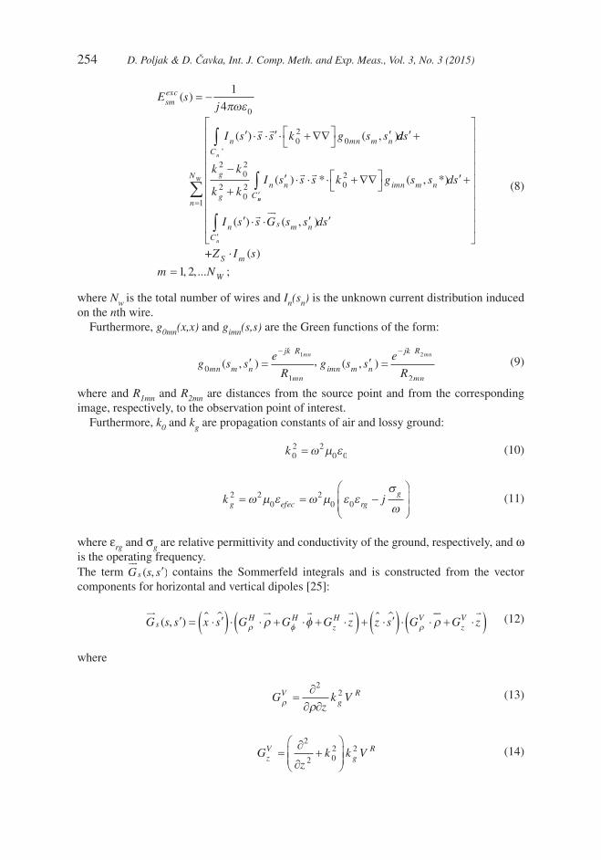
(8)
where Nw is the total number of wires and In(sn) is the unknown current distribution induced on the nth wire.
Furthermore, g0mn(x,x) and gimn(s,s) are the Green functions of the form:
, (9)
where and R1mn and R2mn are distances from the source point and from the corresponding image, respectively, to the observation point of interest.
Furthermore, k0 and kg are propagation constants of air and lossy ground:
(10)
(11)
where εrg and σg are relative permittivity and conductivity of the ground, respectively, and ω is the operating frequency.The term contains the Sommerfeld integrals and is constructed from the vector components for horizontal and vertical dipoles [25]:
(12)
where
(13)
(14)

D. Poljak & D. Čavka, Int. J. Comp. Meth. and Exp. Meas., Vol. 3, No. 3 (2015) 255
(15)
(16)
(17)
(18)
(19)
(20)
(21)
(22)
(23)
2.2 Numerical solution of an integral equation set for overhead wires
The set of Pocklington integro-differential equations (8) is solved using the GB-IBEM. [23,24].
As a first step, at a wire segment the current is expressed in terms of linear combination of shape functions:
(24)
and the implementation of the isoparametric parameters yields
(25)

256 D. Poljak & D. Čavka, Int. J. Comp. Meth. and Exp. Meas., Vol. 3, No. 3 (2015)
where n is the number of local nodes per element.Furthermore, applying the weighted residual approach and utilizing the Galekin–Bubnov
procedure, the set of Pocklington integro-differential equations (8) is transformed into a system of algebraic equations, which is given in the matrix form by
(26)
where is the mutual impedance matrix for the jth observation segment on the mth wire and ith source segment on the nth antenna:
(27)
Note that matrices f and f contain the shape functions while D and D' contain their derivatives.The voltage vector is given by
(28)
and can be evaluated in the close form [24].
2.3 Computational example: transient response of a WT lightning strike
Figure 3a shows WT struck by lightning, while Fig. 3b the corresponding wire antenna representation. WT configuration is modeled by a simple configuration of four PEC wires representing the tower and three blades. Furthermore, the lightning channel is represented by a lossy vertical wire antenna, neglecting the corona effect. Note that the resistance per unit channel length is assumed to be 0.07 Ω/m, as in [19], the wire radius is a = 10 cm. For the sake of simplicity, the current wave along the channel is assumed to propagate at the velocity of light although the realistic current propagation velocity is by the factor of two or three less

D. Poljak & D. Čavka, Int. J. Comp. Meth. and Exp. Meas., Vol. 3, No. 3 (2015) 257
than in the model used in this work. Nevertheless, no significant effects on the distribution of the current wave along the WT are noticed. The lightning return-stroke current is injected by using the equivalent voltage source on the tip of the WT blade.
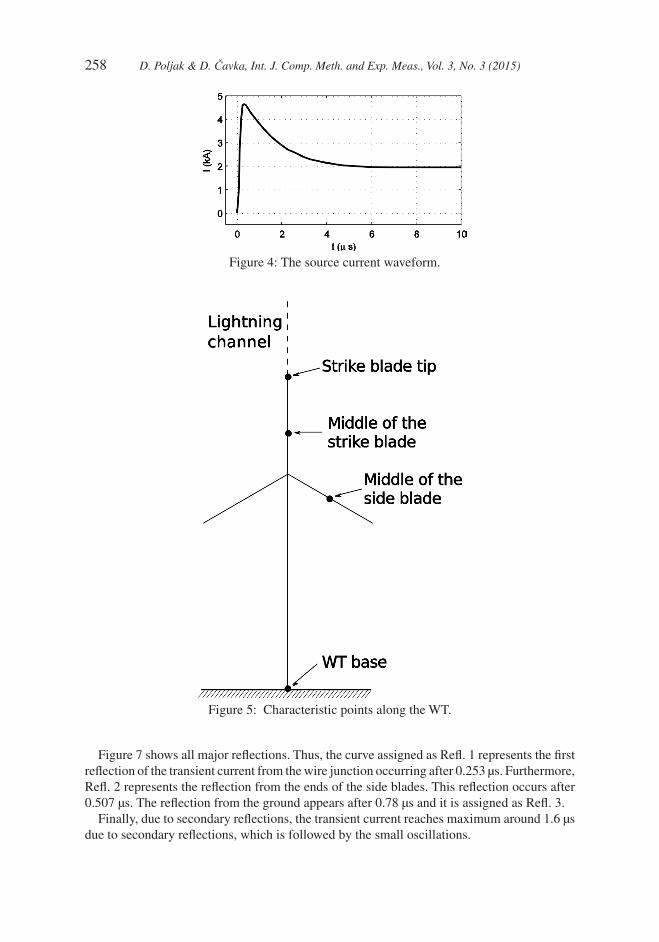
Figure 4 shows the channel base current represented in terms of the Heidler’s function. The current and current derivative peaks are assumed to be 4.7 kA and 25 kA/μs, respectively [19]. The simulations are carried out for the different ground conductivities; PEC ground, 0.01 S/m, 0.001 S/m, 0.1mS/m and εr=10. The grounding wires are not taken into account, as it is shown that they do not influence the current distribution appreciably [17].
The transient current is analyzed at the characteristic points along the WT; strike blade tip, middle of strike blade, middle of side blade, WT base as it is shown in Fig. 5.
Figure 6 shows the transient current induced at different points along the WT (strike blade tip, middle of strike blade, middle of side blade, WT base) for the case of PEC ground. All major reflections are clearly visible, e.g. the maximum value of the transient current at the side blades is five times less than at the strike blade.
The transient at the side blade has significantly shorter duration than in other WT points.Figures 7–10 show transient current waveforms induced at different points along the WT:
strike blade tip, middle of strike blade, middle of side blade and WT base calculated for different values of ground conductivity with permittivity εr = 10. The influence of a finite ground conductivity to the transient current induced along the WT is found to be rather negligible.
Figure 3: Wind turbine struck by lightning and related wire antenna model.
258 D. Poljak & D. Čavka, Int. J. Comp. Meth. and Exp. Meas., Vol. 3, No. 3 (2015)
Figure 7 shows all major reflections. Thus, the curve assigned as Refl. 1 represents the first reflection of the transient current from the wire junction occurring after 0.253 μs. Furthermore, Refl. 2 represents the reflection from the ends of the side blades. This reflection occurs after 0.507 μs. The reflection from the ground appears after 0.78 μs and it is assigned as Refl. 3.
Finally, due to secondary reflections, the transient current reaches maximum around 1.6 μs due to secondary reflections, which is followed by the small oscillations.
Figure 4: The source current waveform.
Figure 5: Characteristic points along the WT.

D. Poljak & D. Čavka, Int. J. Comp. Meth. and Exp. Meas., Vol. 3, No. 3 (2015) 259
Figure 6: Transient induced at different points along WT for the case of PEC ground.
Figure 7: Transient current induced at the strike blade tip.
Figure 8: Transient current induced at the middle of the strike blade.

260 D. Poljak & D. Čavka, Int. J. Comp. Meth. and Exp. Meas., Vol. 3, No. 3 (2015)
3 INTEGRAL EQUATION FORMULATION FOR WTS AS EMI SOURCEThe analysis of WT impact to the radar system operation is carried out by solving the corresponding integral equations via the boundary integral equation method (BIEM) com-bined with PO.
The corresponding EFIE can be derived from Maxwell equations featuring the continuity conditions for the tangential field components.
From the first Maxwell equation, it follows that a time harmonic electric field E can be
expressed in terms of magnetic vector potential A and electric scalar potential j:
E j A= −∇ −ϕ ω (29)
where w stands for operating frequency and magnetic vector potential A r( ) is
A r J re
r rdV r
V
jk r r
( ) ( ) ( )= ′
− ′
′∫∫
− − ′
µ
π4 (30)
Figure 9: Transient current induced at the middle of the side blade.
Figure 10: Transient current induced at WT base.

D. Poljak & D. Čavka, Int. J. Comp. Meth. and Exp. Meas., Vol. 3, No. 3 (2015) 261
where J is the volume current density and μ is the medium permeability.
The electric scalar potential j is expressed in terms of the following integral:
ϕ
πε
ρ( ) ( ) ( )
r re
r rdV r
V
jk r r
= ′
− ′
′∫∫
− − ′
1
4 (31)
where ρ denotes the volume charge density and ε is the medium permittivity. Note that r r− ′
is a distance from the source to the observation point, respectively.Applying the time-harmonic continuity equation [23]:
∇ = −
J jωρ (32)
the scalar potential becomes
ϕ
πωε
( ) ( ) ( )
rj
J re
r rdV r
V
jk r r
= − ′∇ ′
− ′
′∫∫
− − ′
1
4 (33)
For the case of PEC bodies, volume current density is replaced by the surface current
density Js [23].
Consequently, volume integrals eqns (30) and (33) become:
A r J re
r rdS rs
S
jk r r
( ) ( ) ( ’)= ′
− ′∫∫
− − ′
µ
π4 (34)
ϕ
πωε
( ) ( ) ( )
rj
J re
r rdS rS s
S
jk r r
= − ′∇ ′
− ′
′∫∫
− − ′
1
4 (35)
where ∇S denotes the two-dimensional nabla operator.Finally, combining eqns (29), (34) and (35) yields the following representation of the scat-
tered field:
Ej
J re
r rdS r
jJsct
S
jk r r
S= − ′
− ′
′ + ∇ ′∫∫
− − ′
ωµ
π πωε4
1
4( ) ( ) (
SS
jk r r
re
r rdS r∫∫
− − ′
− ′
′
’) ( ) (36)
Furthermore, one obtains the corresponding EFIE by satisfying the continuity conditions for the tangential field components:
nxEtot
tan= 0 (37)
where n is a unit vector normal to the PEC surface.
The total tangential field at the PEC surface can be written as a sum of incident and scattered field, respectively:
E E Etot inc sct
tan tan tan= + (38)

262 D. Poljak & D. Čavka, Int. J. Comp. Meth. and Exp. Meas., Vol. 3, No. 3 (2015)
where
E j Asct
tan tan( )= − +∇ω ϕ (39)
Then EFIE is obtained by combining eqns (36)–(39) and is given by
Ej
J re
r rdS r
jinc
sS
jk r r
Stan ( ) ( )= ′
− ′
′ − ′∇∫∫
− − ′
ωµ
π πωε4
1
4
J re
r rdS rs
S
jk r r
( ) ( )∫∫ ′
− ′
′
− − ′
(40)
Once obtaining the surface current density, it is possible to calculate the scattered field.First, the far-field approximation condition is adopted [22]:
r
D≥
2 2
λ
(41)
where r is the distance from the radiation source to the observation point, D denotes the dimension of the radiation structure and λ is the signal wavelength.
The far-field approximation yields [22]:
E j A= − ω (42)
and the resulting expression for the scattered field is
Ej
J re
r rdS rsct
sS
jk r r
= − ′
− ′
′∫∫
− − ′
ωµ
π4( ) ( ) (43)
Note that expression in eqn (43) is convenient for implementation within the PO approximation.
4 PHYSICAL OPTICS APPROXIMATIONPO is an approximate method for determining surface currents assuming to be locally planar, while the reflection phenomena occur in accordance to the geometrical optics [21,22].
Thus, PO approximation avoids large matrix system, efficiently treating discontinuities and singularities in the high-frequency problems.
4.1 The calculation of the current density using physical optics
In accordance to the geometrical optics, on a part of the object directly illuminated by an incident field, the induced current density is proportional to the incident magnetic field. On the part of the object in the shadow, the current density is assumed to be zero, i.e. [21,22]:
JnxH for ilum part
for shadow parts
inc
=
2
0
, .
,
(44)
where
H inc denotes the magnetic field on the PEC object surface.

D. Poljak & D. Čavka, Int. J. Comp. Meth. and Exp. Meas., Vol. 3, No. 3 (2015) 263
Note that the current density is variable over the entire conducting structure and uniform over the segment.Magnetic and electric field are linked as follows [21,22]:
HkxE
Zinc
inc
=
0
(45)
where Z0 is the free space impedance.Within the far-field approximation, eqn (43) simplifies into:
E
j
re J r e dS rsct jkr
sS
jkr= − ′ ′
− − ′
∫∫ωµ
π4( ) ( ) (46)
thus being convenient for objects having locally planar geometries.Thus, PEC objects are discretized on triangular segments, Fig. 11.Furthermore, in accordance to the PO approximation, on a triangular element surface,
eqn (46) is given by
E
j
re J r e dS rA
sct jkrs
jk r e r r
A
p r p i= − ′ ′
− ⋅ + ⋅
∫∫ωµ
π4( ) ( )
( ) (47)
where A is the area of a triangle, rp is a triangle coordinate and
ri corresponds to the Poyn-
ting vector.
5 ASSESSMENT OF RADAR CROSS-SECTION (RCS)The property of a conducting object to reflect a part of an incident field, as shown in Fig. 12, is defined by means of a radar cross-section (RCS).
RCS of a PEC object provides the information how the object reflects the radar ray in a given direction. The greater the RCS, the greater is the reflected power of the radar signal.
Figure 11: Triangular element geometry.

264 D. Poljak & D. Čavka, Int. J. Comp. Meth. and Exp. Meas., Vol. 3, No. 3 (2015)
Generally, RCS depends not only on the shape and size of the object but also on polarization, frequency and incidence angle of the radar signal [1].
Assuming the PEC object to be in the far field zone, radar signal can be approximated by the plane wave and RCS is defined by the expression:
σ π=→∞
limr
sct
incr
E
E
4 2
2
2 (48)
where Esct is the scattered field, Einc is the field incident to the PEC target and r represents the distance between the target and the radar. Equation (48) is also referred to as a monostatic RCS, as transmitting and receiving antenna of the radar system, respectively, are assumed to be at the same site.
On the other hand, in the case of the bRCS, transmitter and receiver are located at different sites, which is defined by the relation:
σ φ θ π
φ θ
φ θ
π
φ θ
φ θ
,,
,lim
,
,( ) =
( )
( )=
( )
( )→∞
4 4 2
2
2
U
Pr
E
Edr
sct
inc
(49)
For the case of monostatic radar, the ratio of the received and emitted power, respectively, is given by the following radar equation:
P
P
G
rr
t
=
2 2
24 4π
λ
π
σ
( ) (50)
where G stands for the antenna gain, r is the distance from the radar antenna to the conducting object, σ is RCS and λ is the signal wavelength.
Figure 12: Scattering on a PEC object.
D. Poljak & D. Čavka, Int. J. Comp. Meth. and Exp. Meas., Vol. 3, No. 3 (2015) 265
For the bistatic radar, the corresponding radar equation is
P
P
G G
r r
r
t
=
( )
1 22
1 2
24 4π
λ
π
σ (51)
where G1 and G2 is the gain of transmitting and receiving antenna, respectively, while r1 and r2 are the corresponding distances from the antennas to the conducting object.
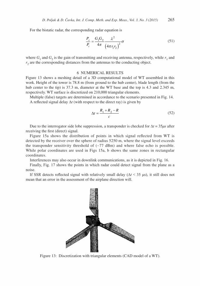
6 NUMERICAL RESULTSFigure 13 shows a meshing detail of a 3D computational model of WT assembled in this work. Height of the tower is 78.8 m (from ground to the hub center), blade length (from the hub center to the tip) is 37.3 m, diameter at the WT base and the top is 4.3 and 2.345 m, respectively. WT surface is discretized on 210,000 triangular elements.
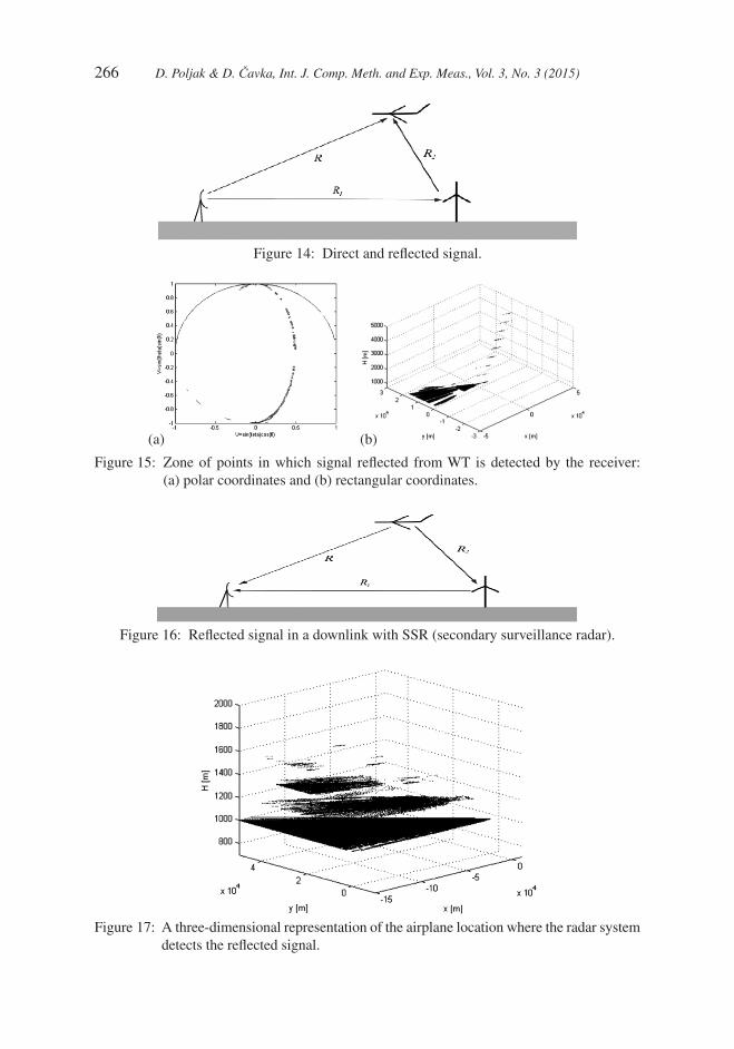
Multiple (false) targets are determined in accordance to the scenario presented in Fig. 14.A reflected signal delay ∆t (with respect to the direct ray) is given by
∆t
R R R
c=
+ −1 2 (52)
Due to the interrogator side lobe suppression, a transponder is checked for ∆t = 35μs after receiving the first (direct) signal.
Figure 15a shows the distribution of points in which signal reflected from WT is detected by the receiver over the sphere of radius 5250 m, where the signal level exceeds the transponder sensitivity threshold of (−77 dBm) and where false echo is possible. While polar coordinates are used in Figs 15a, b shows the same zones in rectangular coordinates.
Interferences may also occur in downlink communications, as it is depicted in Fig. 16.Finally, Fig. 17 shows the points in which radar could detect signal from the plane as a
noise.If SSR detects reflected signal with relatively small delay (∆t < 35 μs), it still does not
mean that an error in the assessment of the airplane direction will.
Figure 13: Discretization with triangular elements (CAD model of a WT).
266 D. Poljak & D. Čavka, Int. J. Comp. Meth. and Exp. Meas., Vol. 3, No. 3 (2015)
Figure 14: Direct and reflected signal.
Figure 16: Reflected signal in a downlink with SSR (secondary surveillance radar).
Figure 17: A three-dimensional representation of the airplane location where the radar system detects the reflected signal.
Figure 15: Zone of points in which signal reflected from WT is detected by the receiver: (a) polar coordinates and (b) rectangular coordinates.
(a) (b)

D. Poljak & D. Čavka, Int. J. Comp. Meth. and Exp. Meas., Vol. 3, No. 3 (2015) 267
7 CONCLUDING REMARKSThis article addresses two EMC aspects pertaining to the analysis and design of WTs:
• A study on WT’s transient behavior due to a direct lightning strike, which involves the assessment of the transient current distribution along WT configuration;
• Analysis of WT as EMI source pertaining to the impact of the radar system operation.
The WT struck by lightning, in accordance to the AT model, is represented by a simple wire configuration while the lightning channel is modeled as the lossy vertical antenna energized by a voltage generator located on the tip of the blade. The current distribution along the structure is governed by the set of the coupled Pocklington integro-differential equations. The effects of the air–ground interface are taken into account via the Sommerfeld integral approach. The corresponding set of integro-differential equations in the frequency domain is solved using the GB-IBEM. Transient response is calculated via the IFFT.
The presented results clearly demonstrate the finite ground conductivity to have a minor effect on the current distribution along the struck WT, which is in accordance to the previously published works pertaining to CN tower.
The WT impact to the radar system operation is formulated via the corresponding surface integral equation for conducting objects. The numerical solution is carried out using the BIEM combined with PO approximation. Once the induced current density over the entire object surface is determined, the related scattered field and the calculation of radar cross- section are carried out. Some illustrative numerical results are presented in this article.
REFERENCES [1] IEC International Standard, Wind turbine generation system – 24: lightning protection,
IEC 61400-24 (2010), International Electro-technical Commission, Geneva. [2] IEA, Recommended practices for wind turbine testing and evaluation, 9. Lightning
Protection for wind turbine installations, 1997 edn, IEA, Geneva, 1997. [3] IEE Professional Group S1, New concepts in the generation, distribution and use of
electrical energy: half-day colloquium on “Lightning protection of wind turbines”, 1997, p. 11.
[4] Sorensen, T., Sorensen, J.T. & Nielsen, H., Lightning damages to power generating wind turbines, Proceedings of the 24th International Conference on Lightning Protection (ICLP98), 1998, pp. 176–179.
[5] McNiff, B., Wind turbine lightning protection project 1999–2001. NREL Subcontractor Report, SR-500-31115, 2002.
[6] Rachidi, F., Rubinstein, M., Montanya, J., et al., A review of current issues in lightning protection of new-generation wind turbine blades. IEEE Transactions on Industrial Elec-tronics, 55(6), pp. 2489–2496, 2008. doi: http://dx.doi.org/10.1109/tie.2007.896443
[7] Yoh, Y., Toshiaki, F. & Toshiaki, U., How does ring earth electrode effect to wind turbine? 42nd International Universities Power Engineering Conference, UPEC 2007, pp. 796–799, 2007.
[8] Glushakow, B., Effective lightning protection for windturbine generators. IEEE Transactions on Energy Conversion, 22(1), pp. 214–222, 2007. doi: http://dx.doi.org/ 10.1109/tec.2006.889622
[9] IEC International Standard, Protection against lightning – Part 3: physical damage to structures and life hazard, IEC 62305-3, International Electro-technical Commission, Geneva, 2006.

268 D. Poljak & D. Čavka, Int. J. Comp. Meth. and Exp. Meas., Vol. 3, No. 3 (2015)
[10] Rakov, V.A., Transient response of a tall object to lightning. IEEE Transactions on Electro magnetic Compatibility, 43(4), pp. 654–661, 2001. doi: http://dx.doi.org/ 10.1109/15.974646
[11] Rakov, V.A. & Uman, M.A., Review and evaluation of lightning return stroke models including some aspects of their application. IEEE Transactions on Electromagnetic Compatibility, 40(4), pp. 403–426, 1998. doi: http://dx.doi.org/10.1109/15.736202
[12] Rachidi, F., Rakov, V.A., Nucci, C.A. & Bermudez, J.L., The effect of vertically-extended strike object on the distribution of current along the lightning channel. Journal of Geophysical Research, 107(D23), p. 4699, 2002. doi: http://dx.doi.org/ 10.1029/2002jd002119
[13] Pavanello, D., Rachidi, F., Rakov, V.A., Nucci, C.A. & Bermudez, J.L., Return stroke current profiles and electromagnetic fields associated with lightning strikes to tall towers: comparison of engineering models. Journal of Electrostatics, 65, pp. 316–321, 2007. doi: http://dx.doi.org/10.1016/j.elstat.2006.09.014
[14] Podgorski, S. & Landt, J.A., Three dimensional time domain modeling of lightning. IEEE Transactions on Power Delivery, 2(3), pp. 931–938, 1987. doi: http://dx.doi.org/10.1109/tpwrd.1987.4308198
[15] Petrache, E., Rachidi, F., Pavanello, D., et al., Lightning strikes to elevated structures: influence of grounding conditions on currents and electromagnetic fields, Presented at IEEE International Symposium on Electromagnetic Compatibility, Chicago, 2005.
[16] Petrache, E., Rachidi, F., Pavanello, D., et al., Influence of the finite ground conductivity on the transient response to lightning of a tower and its grounding, Presented at 28th General Assembly of International Union of Radio Science (URSI), New Delhi, India, 2005.
[17] Podgorski, S. & Landt, J.A., Numerical analysis of the lightning–CN tower interaction, Presented at 6th Symposium and Technical Exhibition on Electromagnetic Compatibility, Zurich, Switzerland, 1985.
[18] Baba, Y. & Ishii, M., Numerical electromagnetic field analysis of lightning current in tall structures. IEEE Transactions on Power Delivery, 16(2), pp. 324–328, 2001. doi: http://dx.doi.org/10.1109/61.915502
[19] Kordi, B., Moini, R., Janischewskyj, W., et al., Application of the antenna theory model to a tall tower struck by lightning. Journal of Geophysical Research, 108(D17), 2003. doi: http://dx.doi.org/10.1029/2003jd003398
[20] Matthews, J.C.G., Sarno, C. & Herring, R., Interaction between radar systems and wind farms, 2008 Loughborow Antennas & Propagation Conference, Loughborrow, UK, March 2008.
[21] Jin, M., Theory and Computation of Electromagnetic Fields, IEEE Press–Wiley: New Jersey, USA, 2010.
[22] Yamashita (ed.), Analysis Methods for Electromagnetic Wave Propagation, Artech House: London, 1996.
[23] Poljak, D., Advanced Modeling in Computational EMC, Wiley: New York, 2007.[24] Poljak, D. & Drissi, K.E.K., Electromagnetic field coupling to overhead wire
configurations: antenna model versus transmission line approach. International Journal of Antennas and Propagation, pp. 1–18, 2012. doi: http://dx.doi.org/ 10.1155/2012/730145
[25] Burke, G.J. & Miller, E.K., Modeling antennas near to and penetrating a lossy interface. IEEE Transactions on Antenna and Propagation, 32(10), pp. 1040–1049, 1984. doi: http://dx.doi.org/10.1109/tap.1984.1143220