Embed Size (px)
Citation preview

Electrodeposited Mn-Co Alloy
Coating for SOFC Interconnects
H.A. McCrabb1, B. Kagajwala1 T.D. Hall1, H. Zhang2,
X. Liu2, S. Snyder1 E.J. Taylor1
1Faraday Technology, Inc. 315 Huls Dr., Clayton, OH 45315 2West Virginia University, Dept. of Mechanical Aerospace Eng. ESB,
Morgantown, WV 26506
13th Annual SECA Workshop
July 25, 2012

PSI Employees
by Education
PSI Locations
Faraday Technology, Inc.
• Faraday Technology specializes
in electrochemical engineering
• www.faradaytechnology.com
• Faraday is a wholly-owned
subsidiary of Physical Sciences,
Inc. (Boston, MA)
• www.psicorp.com
• Collectively, the company
staffs ~185 employees - ~100
with PhDs
• Annual revenue of ~ $50M
slide 2 13th Annual SECA Workshop Pittsburgh, PA, July 24-25, 2012
Platform Technology: Pulse/Pulse
Reverse Processing
Core Competency: Design and Engineer of Novel Electrochemical
Hardware
Total Manufacturing
Solution
• Electronics
• Edge and Surface Finishing
• Engineered Coatings
• Battery and Fuel Cell Power
• Environmental Systems
• Corrosion and Monitoring
Services
• Enables uniform processing
• Applicable for additive or
subtractive electrochemical
processes
• Uniform processing is
achieved over entire substrate,
improving end product
reliability
Either may be applied independently to
improve current industrial practices or may be
combined for a total manufacturing solution
Faraday Technology, Inc.
slide 4 13th Annual SECA Workshop Pittsburgh, PA, July 24-25, 2012
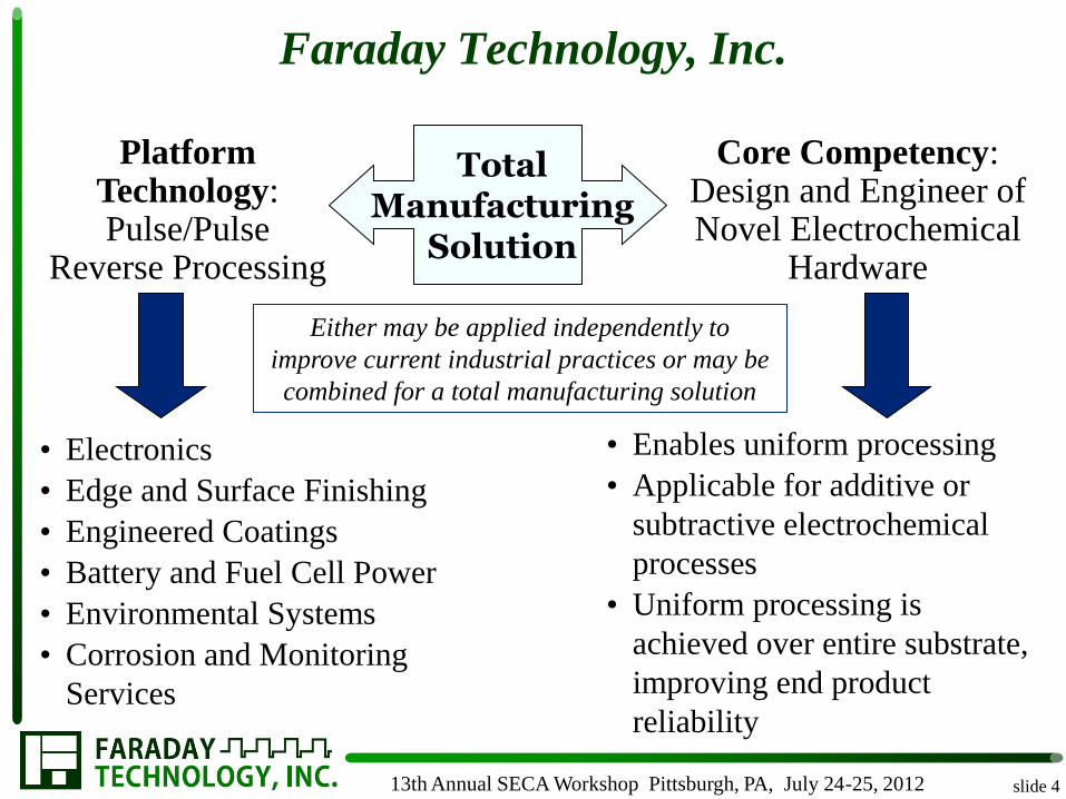
Achievements
slide 5
• Continued optimization of FARADAYICSM Electrodeposition
Process parameters in order to optimize coating thickness, coating
composition and coating adhesion
• Improved coating uniformity across T441 planar interconnects at
the 100 cm2 scale
• Demonstrated coating process for 25 cm2 430 stainless steel
interconnect containing gas flow fields
• Continued refinement of economic analysis to assess economic
viability of FARADAYICSM Electrodeposition Process for high
volume batch manufacturing
13th Annual SECA Workshop Pittsburgh, PA, July 24-25, 2012

slide 6
FARADAYICSM Processing
Ap
pli
ed E
( - )
Cathodic
Anodic( + )
Forward
modulation
Offtime
Time
Forward
modulation
t1 t0Ap
pli
ed E
( - )
Cathodic
Anodic( + )
Forward
modulation
Offtime
Time
t2
V1
Forward
modulation
Reverse
modulation
(b)(a)
V1
V2
t1
t0
t1
FARADAYICSM Process
+
Conventional (DC) Electrodeposition
• Fast deposition rates
• Simple deposition equipment
• Non-line-of-sight deposition
• Industrially scalable
• Improved electric field control
– Enhanced control of coating thickness
uniformity
– Enhanced control of alloy composition
• Improved coating of “hidden surfaces”
13th Annual SECA Workshop Pittsburgh, PA, July 24-25, 2012

Coating Process
slide 7
• Surface pretreatment to
remove oxide and enhance
coating adhesion
• Electrodeposition to coat
interconnects with Mn-Co
alloy
– Pulse and pulse reverse
electric fields to control
deposit properties
• Elevated thermal treatment
to convert alloy to spinel
Acetone&
Scrub Grit Blast
Rinse&
Scrub
Pickle Dip Rinse Plate
Acetone&
Scrub Grit Blast
Rinse&
Scrub
Pickle Dip Rinse Plate
13th Annual SECA Workshop Pittsburgh, PA, July 24-25, 2012

Phase I Hull Cell Experiments
slide 9
Enables investigation into the effect of various
parameters on deposit properties during a single
experiment
– Current density
– Temperature
– Electrolyte composition
– Additives
13th Annual SECA Workshop Pittsburgh, PA, July 24-25, 2012

Phase I Hull Cell Experiments
slide 10
• Electrolyte without
NaC6H11O7 was selected for
Phase I work on 5 cm x 5 cm
T441 planar substrates
because at reasonable current
densities and metal ion
concentrations results
suggested
– Potential for higher Mn
content in coating
– Less microcracking
– Higher current efficiency
• Faster coating deposition
rates
13th Annual SECA Workshop Pittsburgh, PA, July 24-25, 2012

Phase I Cr Diffusion and Coating Porosity
• Cross-sections of samples that
underwent a soak treatment at
800 C for 500 hrs.
– Coating thickness was as
deposited
– Indicates that the 3 micron
layer has low Cr diffusion and
the 10 micron coating has
negligible Cr diffusion into
coating
– 3 micron coating appears
more porous than 7 and 10
micron film
Substrate Coating surface
slide 11 13th Annual SECA Workshop Pittsburgh, PA, July 24-25, 2012

Phase I Coating Crystal Structure
10 20 30 40 50 60 70
334
2 theta (degrees)
Inte
ns
ity
(a
.u.)
MnCo2O
4
Mn1.5
Co1.5
O4
Mn1.5
CrO4
332
333
40%Co 3µm
40%Co 7µm
40%Co 10µm
Crystal Structure after 500 hrs. at 800 C
Inte
nsi
ty (
a.u
.)
2 theta (degrees)
slide 12 13th Annual SECA Workshop Pittsburgh, PA, July 24-25, 2012

Phase I Effect of Thickness and Composition
on Performance
slide 13
The ASR is 60 mΩ cm2 in most cases regardless of compositions
and thickness after 500 hrs. at 800 C
500 600 700 800
0
500
1000
1500
Temperature ( )
AS
R (
m c
m2)
336
337
ASR Behavior after 500 hrs.
85%Co 7µm
85%Co 10µm
mΩ cm2 100 hr 200 hr 500 hr
3 μm 40% Co 35 57 49
7 μm 40% Co 62 7 32
10 μm 40% Co 22 - 36
3 μm 85% Co 31 75 20
7 μm 85% Co 59 40 54
10 μm 85% Co 37 23 22
3 μm 57% Co - 34 26
7 μm 57% Co - - 12
10 μm 57% Co - - 12
ASR at 800 C
13th Annual SECA Workshop Pittsburgh, PA, July 24-25, 2012
mΩ cm
2 100 hr 200 hr 500 hr
3 μm 40% Co 35 57 49
7 μm 40% Co 62 7 32
10 μm 40% Co 22 - 36
3 μm 85% Co 31 75 20
7 μm 85% Co 59 40 54
10 μm 85% Co 37 23 22
3 μm 57% Co - 34 26
7 μm 57% Co - - 12
10 μm 57% Co - - 12

Phase III Program Management Plan
slide 14
Milestones
Fiscal
Year Title
Planned
Completion
Percent
Complete
2011 1. Design/modification of 10” x 10” electrodeposition cell May 2011 100%
2012 2. Long-term high temperature, thermal evaluation August 2012 70%
2012 3. Process development for 4”x4” planar interconnects May 2012 100%
2012 4. Process development for 4”x4” pattern interconnects June 2012 10%
2012 5. Long-term on-cell performance evaluation August 2012 10%
2012 6. Qualification/demonstration of IC in single cell test rig September 2012 0%
13th Annual SECA Workshop Pittsburgh, PA, July 24-25, 2012

Pilot Scale Electrodeposition Equipment
slide 15
Based upon Faraday’s electrochemical cell design that facilitates uniform flow across the surface
of a flat substrate (US patent #7,553,401)
13th Annual SECA Workshop Pittsburgh, PA, July 24-25, 2012
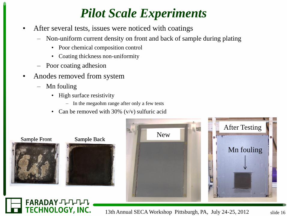
Pilot Scale Experiments
slide 16
• After several tests, issues were noticed with coatings
– Non-uniform current density on front and back of sample during plating
• Poor chemical composition control
• Coating thickness non-uniformity
– Poor coating adhesion
• Anodes removed from system
– Mn fouling
• High surface resistivity
– In the megaohm range after only a few tests
• Can be removed with 30% (v/v) sulfuric acid
Sample Front Sample BackSample Front Sample BackNew
After Testing
Mn fouling
13th Annual SECA Workshop Pittsburgh, PA, July 24-25, 2012

NaC6H11O7 Electrolyte Revisited
slide 17
• Addition of NaC6H11O7 to electrolyte
– Observed benefits
• Boric acid dissolves completely
• Complexing metal ions prevents hydroxide
formation
• Improved buffer capacity
• Anode fouling eliminated
• Improved coating adhesion in as-deposited
state
• Coating deposition rate appears linear
• Maintain coating thickness upon spinel
conversion
~ 20 μm coating
~ 21 μm coating
~3 μm Cr2O3
13th Annual SECA Workshop Pittsburgh, PA, July 24-25, 2012
1110
1110

Varying Coating Thickness
slide 18 13th Annual SECA Workshop Pittsburgh, PA, July 24-25, 2012
~ 33 μm coating
~ 3 μm Cr2O3
1108
0
10
20
30
40
50
60
70
0 5 10 15 20 25 30 35 40 45
Rela
tive a
t%
Distance (microns)
C K O K AlK CrK MnK FeK CoK
0
10
20
30
40
50
60
70
80
0 1 2 3 4 5 6 7 8 9 10 11 12 13 14 15 16 17 18 19 20 21 22 23
at%
Distance (microns)
C K O K AlK CrK MnK FeK CoK
~ 10 μm coating
~ 2 μm Cr2O3
1144
~ 21μm coating
~ 3 μm Cr2O3
0
10
20
30
40
50
60
70
80
0 1 2 3 4 5 6 7 8 9 10 11 12 13 14 15 16 17 18 19 20 21 22 23
at%
Distance (microns)
C K O K AlK CrK MnK FeK CoK
1110
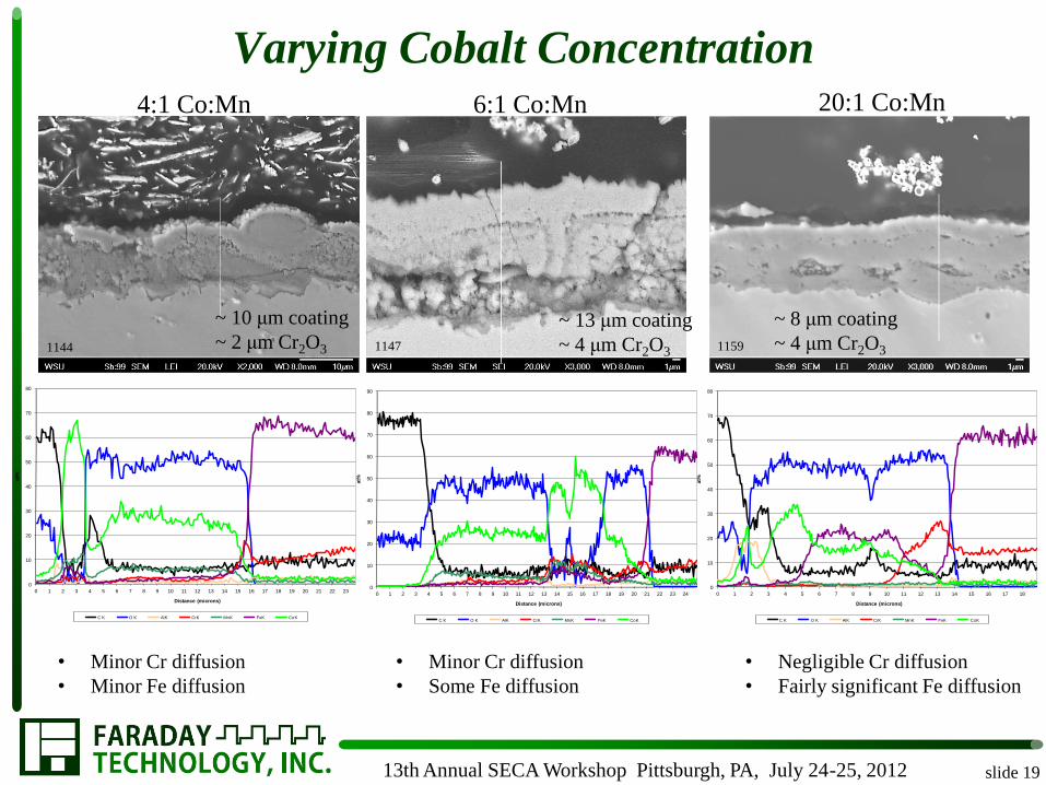
Varying Cobalt Concentration
slide 19 13th Annual SECA Workshop Pittsburgh, PA, July 24-25, 2012
4:1 Co:Mn 6:1 Co:Mn 20:1 Co:Mn
~ 8 μm coating
~ 4 μm Cr2O3
~ 13 μm coating
~ 4 μm Cr2O3
~ 10 μm coating
~ 2 μm Cr2O3 1144 1147 1159
0
10
20
30
40
50
60
70
80
0 1 2 3 4 5 6 7 8 9 10 11 12 13 14 15 16 17 18 19 20 21 22 23
at%
Distance (microns)
C K O K AlK CrK MnK FeK CoK
0
10
20
30
40
50
60
70
80
90
0 1 2 3 4 5 6 7 8 9 10 11 12 13 14 15 16 17 18 19 20 21 22 23 24
at%
Distance (microns)
C K O K AlK CrK MnK FeK CoK
0
10
20
30
40
50
60
70
80
0 1 2 3 4 5 6 7 8 9 10 11 12 13 14 15 16 17 18
at%
Distance (microns)
C K O K AlK CrK MnK FeK CoK
• Negligible Cr diffusion
• Fairly significant Fe diffusion
• Minor Cr diffusion
• Some Fe diffusion
• Minor Cr diffusion
• Minor Fe diffusion

slide 20 13th Annual SECA Workshop Pittsburgh, PA, July 24-25, 2012
2 hr. thermal treatment in
air atm prior to thermal soak
2 hr. thermal treatment in H2
atm prior to thermal soak
750 Hour Thermal Soak at 800 C
1136 1137
1137 1136
After 750 hr.
thermal soak
After 750 hr.
thermal soak

750 Hour Thermal Soak at 800 C
slide 21 13th Annual SECA Workshop Pittsburgh, PA, July 24-25, 2012
2 hr. thermal treatment in
air atm prior to thermal soak
2 hr. thermal treatment in H2
atm prior to thermal soak
1136 1137
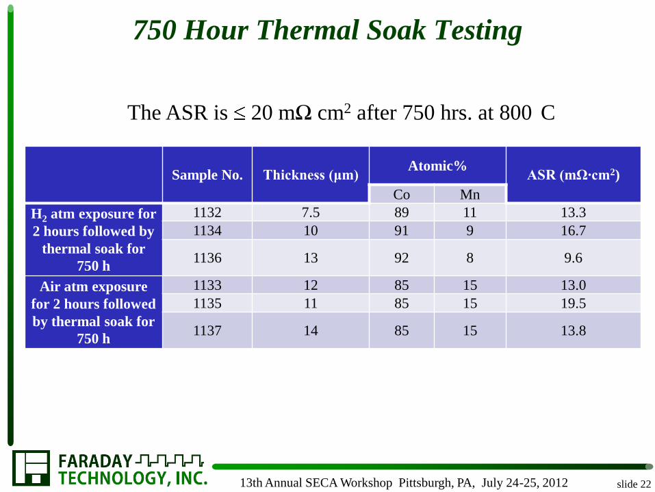
750 Hour Thermal Soak Testing
slide 22 13th Annual SECA Workshop Pittsburgh, PA, July 24-25, 2012
Sample No. Thickness (μm) Atomic%
ASR (mΩ·cm2)
Co Mn
H2 atm exposure for
2 hours followed by
thermal soak for
750 h
1132 7.5 89 11 13.3
1134 10 91 9 16.7
1136 13 92 8 9.6
Air atm exposure
for 2 hours followed
by thermal soak for
750 h
1133 12 85 15 13.0 1135 11 85 15 19.5
1137 14 85 15 13.8
The ASR is 20 mΩ cm2 after 750 hrs. at 800 C

750 Hour Thermal Soak
slide 23 13th Annual SECA Workshop Pittsburgh, PA, July 24-25, 2012
0
10
20
30
40
50
60
70
80
90
0 1 2 3 4 5 6 7 8 9 10 11 12 13 14 15 16 17 18 19 20 21 22 23 24 25 26 27 28 29 30 31 32 33 34 35 36
at%
Distance (microns)
C K O K AlK CrK MnK FeK CoK
800 C 850 C
1123D 1137

Process Scale-up from 25 cm2 to 100 cm2
Coating thickness and
compositional uniformity
at the 100 cm2 scale
– 6:1 Co:Mn
– ~ 12 m coating
– ~4 m Cr2O3 scale
slide 24
CD
B A
E
B A
D C
F E
T441 substrate
MnCo coating
T441 substrate
MnCo coating
F
As-deposited Post-thermal treatment
13th Annual SECA Workshop Pittsburgh, PA, July 24-25, 2012

slide 25 13th Annual SECA Workshop Pittsburgh, PA, July 24-25, 2012
0
200
400
600
800
1000
1200
1400
0 1 2 3 4 5 6 7 8 9 10 11 12 13 14 15 16 17 18 19 20 21 22 23
Co
un
ts
Distance (microns)
C K O K AlK CrK MnK FeK CoK
0
200
400
600
800
1000
1200
1400
0 1 2 3 4 5 6 7 8 9 10 11 12 13 14 15 16 17 18 19 20 21 22 23
Co
un
ts
Distance (microns)
C K O K AlK CrK MnK FeK CoK
0
200
400
600
800
1000
1200
1400
0 1 2 3 4 5 6 7 8 9 10 11 12 13 14 15 16 17 18
Co
un
ts
Distance (microns)
C K O K AlK CrK MnK FeK CoK
CD
B A
E
B A
D C
F E
T441 substrate
MnCo coating
T441 substrate
MnCo coating
F
CD
B A
E
B A
D C
F E
T441 substrate
MnCo coating
T441 substrate
MnCo coating
F
Process Scale-up from 25 cm2 to 100 cm2

25 cm2 430 Stainless Steel Interconnect With
Gas Flow Fields
slide 26 13th Annual SECA Workshop Pittsburgh, PA, July 24-25, 2012
~11 m
~8 m
~15 m
T441 substrate
MnCo coating
~21 m~18 m
• 3 channel serpentine pattern
• Channel width ~ 0.9 mm
• Rib width ~ 0.8 mm
• Channel depth ~ 0.45 mm

slide 27 13th Annual SECA Workshop Pittsburgh, PA, July 24-25, 2012
25 cm2 430 SS Interconnect With Gas Flow Fields
0
10
20
30
40
50
60
70
80
0 1 2 3 4 5 6 7 8 9 10 11 12 13 14 15 16 17 18 19 20 21 22 23 24 25 26 27 28 29 30
at%
Distance (microns)
C K O K AlK CrK MnK FeK CoK
0
10
20
30
40
50
60
70
80
0 1 2 3 4 5 6 7 8 9 10 11 12 13 14 15 16 17 18 19 20 21 22 23 24 25 26 27 28 29 30 31 32
at%
Distance (microns)
C K O K AlK CrK MnK FeK CoK
Top left of channel
Bottom left of channel

25 cm2 430 SS Interconnect With Gas Flow Fields
slide 28 13th Annual SECA Workshop Pittsburgh, PA, July 24-25, 2012
0
10
20
30
40
50
60
70
80
0 2 4 6 8 10 12 14 16 18 20 22 24 26 28 30 32 34 36 38 40 42 44
at%
Distance (microns)
C K O K AlK CrK MnK FeK CoK
0
10
20
30
40
50
60
70
80
90
0 2 4 6 8 10 12 14 16 18 20 22 24 26 28 30 32 34 36 38 40 42 44 46 48
at%
Distance (microns)
C K O K AlK CrK MnK FeK CoK
Bottom of channel
Bottom right of channel

Future Work
• Complete thermal soak to 2000 hours for existing samples
• Development, optimization and validation of the
FARADAYICSM Electrodeposition Process for 100 cm2
interconnects with gas flow field features
• Long-term on-cell performance evaluation of button cells
• Qualification/Demonstration of Interconnect Coating in
Single Cell Test Rig under ideal SOFC operating
conditions by potential commercial partners
• Continued development of a more comprehensive
economic assessment of the electrodeposition coating
process as it relates to interconnect manufacturing.
slide 29 13th Annual SECA Workshop Pittsburgh, PA, July 24-25,
2012

Acknowledgments
slide 30
• Briggs White and the entire NETL SECA team
• This material is based upon work supported by the Department of Energy under Award Nos. DE-SC0001023 and DE-FE0006165. Any opinions, findings, conclusions and recommendations expressed in this material are those of the authors and do not necessarily reflect the views of the DOE.
• Contact Information: Heather McCrabb
Ph: 937-836-7749
Email: [email protected]
13th Annual SECA Workshop Pittsburgh, PA, July 24-25, 2012