Embed Size (px)
Citation preview
Electrochemistrya Chem1 Supplement Text
Stephen K. LowerSimon Fraser University
Contents
1 Chemistry and electricity 2Electroneutrality . . . . . . . . . . . . . . . . . . . . . . . . . . . . . . 3Potential differences at interfaces . . . . . . . . . . . . . . . . . . . . . 4
2 Electrochemical cells 5Transport of charge within the cell . . . . . . . . . . . . . . . . . . . . 7Cell description conventions . . . . . . . . . . . . . . . . . . . . . . . . 8Electrodes and electrode reactions . . . . . . . . . . . . . . . . . . . . 8
3 Standard half-cell potentials 10Reference electrodes . . . . . . . . . . . . . . . . . . . . . . . . . . . . 12Prediction of cell potentials . . . . . . . . . . . . . . . . . . . . . . . . 13Cell potentials and the electromotive series . . . . . . . . . . . . . . . 14Cell potentials and free energy . . . . . . . . . . . . . . . . . . . . . . 15The fall of the electron . . . . . . . . . . . . . . . . . . . . . . . . . . . 17Latimer diagrams . . . . . . . . . . . . . . . . . . . . . . . . . . . . . . 20
4 The Nernst equation 21Concentration cells . . . . . . . . . . . . . . . . . . . . . . . . . . . . . 23Analytical applications of the Nernst equation . . . . . . . . . . . . . . 23
Determination of solubility products . . . . . . . . . . . . . . . . 23Potentiometric titrations . . . . . . . . . . . . . . . . . . . . . . . 24Measurement of pH . . . . . . . . . . . . . . . . . . . . . . . . . . 24
Membrane potentials . . . . . . . . . . . . . . . . . . . . . . . . . . . . 26
5 Batteries and fuel cells 29The fuel cell . . . . . . . . . . . . . . . . . . . . . . . . . . . . . . . . . 29
1 CHEMISTRY AND ELECTRICITY 2
6 Electrochemical Corrosion 31Control of corrosion . . . . . . . . . . . . . . . . . . . . . . . . . . . . 34
7 Electrolytic cells 34Electrolysis involving water . . . . . . . . . . . . . . . . . . . . . . . . 35Faraday’s laws of electrolysis . . . . . . . . . . . . . . . . . . . . . . . 36Industrial electrolytic processes . . . . . . . . . . . . . . . . . . . . . . 37
The chloralkali industry. . . . . . . . . . . . . . . . . . . . . . . . 37Electrolytic refining of aluminum . . . . . . . . . . . . . . . . . . 38
1 Chemistry and electricity
The connection between chemistry and electricity is a very old one, going backto Allesandro Volta’s discovery, in 1793, that electricity could be produced byplacing two dissimilar metals on opposite sides of a moistened paper. In 1800,Nicholson and Carlisle, using Volta’s primitive battery as a source, showed thatan electric current could decompose water into oxygen and hydrogen. This wassurely one of the most significant experiments in the history of chemistry, for itimplied that the atoms of hydrogen and oxygen were associated with positiveand negative electric charges, which must be the source of the bonding forcesbetween them. By 1812, the Swedish chemist Berzelius could propose that allatoms are electrified, hydrogen and the metals being positive, the nonmetalsnegative. In electrolysis, the applied voltage was thought to overpower theattraction between these opposite charges, pulling the electrified atoms apart inthe form of ions (named by Berzelius from the Greek for “travellers”). It wouldbe almost exactly a hundred years later before the shared electron pair theoryof G.N. Lewis could offer a significant improvement over this view of chemicalbonding.
1 CHEMISTRY AND ELECTRICITY 3
AAAAAAAAAA
-
AAAAAAAAAAAAZn
e-
Zn in metal
dissolution of Zn as Zn2+ causes electric charges to build up in the two phases which inhibits further dissolution
Zn2+(aq)
e-
Zn2+(aq)
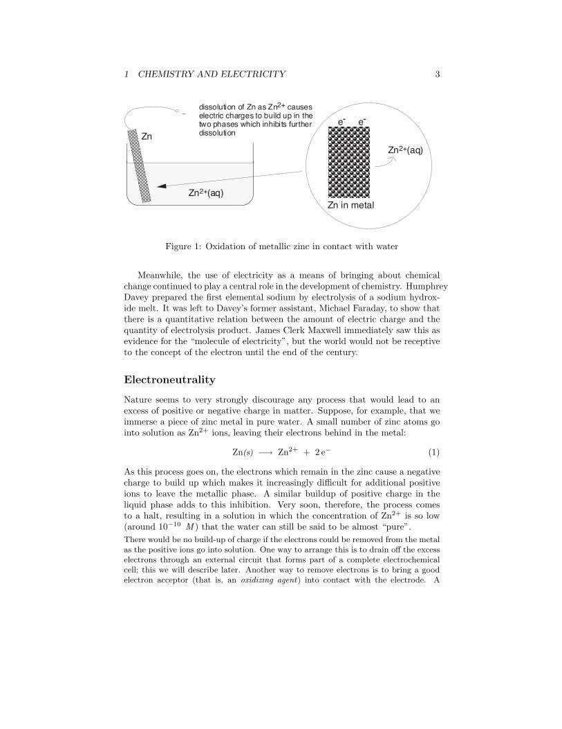
Figure 1: Oxidation of metallic zinc in contact with water
Meanwhile, the use of electricity as a means of bringing about chemicalchange continued to play a central role in the development of chemistry. HumphreyDavey prepared the first elemental sodium by electrolysis of a sodium hydrox-ide melt. It was left to Davey’s former assistant, Michael Faraday, to show thatthere is a quantitative relation between the amount of electric charge and thequantity of electrolysis product. James Clerk Maxwell immediately saw this asevidence for the “molecule of electricity”, but the world would not be receptiveto the concept of the electron until the end of the century.
Electroneutrality
Nature seems to very strongly discourage any process that would lead to anexcess of positive or negative charge in matter. Suppose, for example, that weimmerse a piece of zinc metal in pure water. A small number of zinc atoms gointo solution as Zn2+ ions, leaving their electrons behind in the metal:
Zn(s) −→ Zn2+ + 2 e− (1)
As this process goes on, the electrons which remain in the zinc cause a negativecharge to build up which makes it increasingly difficult for additional positiveions to leave the metallic phase. A similar buildup of positive charge in theliquid phase adds to this inhibition. Very soon, therefore, the process comesto a halt, resulting in a solution in which the concentration of Zn2+ is so low(around 10−10 M ) that the water can still be said to be almost “pure”.There would be no build-up of charge if the electrons could be removed from the metalas the positive ions go into solution. One way to arrange this is to drain off the excesselectrons through an external circuit that forms part of a complete electrochemicalcell; this we will describe later. Another way to remove electrons is to bring a goodelectron acceptor (that is, an oxidizing agent) into contact with the electrode. A
1 CHEMISTRY AND ELECTRICITY 4
suitable electron acceptor would be hydrogen ions; this is why acids attack manymetals. For the very active metals such as sodium, H2O is a sufficiently good electronacceptor.
The degree of charge unbalance that is allowed produces differences in elec-tric potential of no more than a few volts, and corresponds to concentration un-balances of oppositely charged particles that are not even detectable by ordinarychemical means. There is nothing mysterious about this prohibition, known asthe electroneutrality principle; it is a simple consequence of the thermodynamicwork required to separate opposite charges, or to bring like charges into closercontact. The additional work raises the free energy ∆G of the process, makingit less spontaneous.
The only way we can get the reaction in Eq 1 to continue is to coupleit with some other process that restores electroneutrality to the two phases.A simple way to accomplish this would be immerse the zinc in a solution ofcopper sulfate instead of pure water. As you will recall if you have seen thiscommonly-performed experiment carried out, the zinc metal quickly becomescovered with a black coating of finely-divided metallic copper. The reaction isa simple oxidation-reduction process, a transfer of two electrons from the zincto the copper:
Zn(s) −→ Zn2+ + 2 e− Cu2+ + 2 e− −→ Cu(s)
The dissolution of the zinc is no longer inhibited by a buildup of negative chargein the metal, because the excess electrons are removed from the zinc by copperions that come into contact with it. At the same time, the solution remainselectrically neutral, since for each Zn2+ introduced to the solution, one Cu2+ isremoved. The net reaction
Zn(s) + Cu2+ −→ Zn2+ + Cu(s)
quickly goes to completion.
Potential differences at interfaces
Electrochemistry is the study of reactions in which charged particles (ions orelectrons) cross the interface between two phases of matter, typically a metallicphase (the electrode) and a conductive solution, or electrolyte. A process of thiskind is known generally as an electrode process.
Electrode processes (reactions) take place at the surface of the electrode,and produce a slight unbalance in the electric charges of the electrode and thesolution. The result is an interfacial potential difference which, as we saw above,can materially affect the rate and direction of the reaction. Much of the impor-tance of electrochemistry lies in the ways that these potential differences can berelated to the thermodynamics and kinetics of electrode reactions. In particular,
2 ELECTROCHEMICAL CELLS 5
AAAAA
AAAAAAAAAAAAAAAAAA
AAAAAAAAAAAAAAAAAA
Zn2+Cu2+
NO3Ð
Zn Cu
direction of electron flow in external circuit
direction of conventional current flow
Zn ê Zn2+,NO3Ð êê Cu2+, NO3
Ð ê Cu
porous fritted glass barrier
Ð +
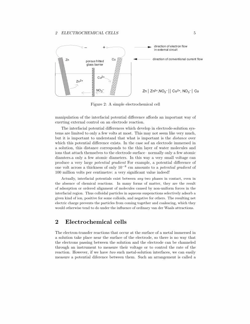
Figure 2: A simple electrochemical cell
manipulation of the interfacial potential difference affords an important way ofexerting external control on an electrode reaction.
The interfacial potential differences which develop in electrode-solution sys-tems are limited to only a few volts at most. This may not seem like very much,but it is important to understand that what is important is the distance overwhich this potential difference exists. In the case sof an electrode immersed ina solution, this distance corresponds to the thin layer of water molecules andions that attach themselves to the electrode surface– normally only a few atomicdiamters.a only a few atomic diameters. In this way a very small voltage canproduce a very large potential gradient For example, a potential difference ofone volt across a thickness of only 10−8 cm amounts to a potential gradient of100 million volts per centimetre: a very significant value indeed!
Actually, interfacial potentials exist between any two phases in contact, even in
the absence of chemical reactions. In many forms of matter, they are the result
of adsorption or ordered alignment of molecules caused by non-uniform forces in the
interfacial region. Thus colloidal particles in aqueous suspenctions selectively adsorb a
given kind of ion, positive for some colloids, and negative for others. The resulting net
electric charge prevents the particles from coming together and coalescing, which they
would otherwise tend to do under the influence of ordinary van der Waals attractions.
2 Electrochemical cells
The electron-transfer reactions that occur at the surface of a metal immersed ina solution take place near the surface of the electrode, so there is no way thatthe electrons passing between the solution and the electrode can be channeledthrough an instrument to measure their voltage or to control the rate of thereaction. However, if we have two such metal-solution interfaces, we can easilymeasure a potential diference between them. Such an arrangement is called a
2 ELECTROCHEMICAL CELLS 6
galvanic cell. A typical cell might consists of two pieces of metal, one zinc andthe other copper, each immersed each in a solution containing a dissolved saltof the corresponding metal (see Fig. 2). The two solutions are connected by atube containing a porous barrier that prevents them from rapidly mixing butallows ions to diffuse through.
If we simply left it at that, each metal would just sit in its own solution,and no significant amount of reaction would take place. However, if we connectthe zinc and copper by means of a metallic conductor, the excess electrons thatremain when Zn2+ ions go into solution in the left cell would be able to flowthrough the external circuit and into the right electrode, where they could bedelivered to the Cu2+ ions that are converted into Cu atoms at the surface ofthe copper electrode. The net reaction is the same as before:
Zn(s) + Cu2+ −→ Zn2+ + Cu(s)
but this time, the oxidation and reduction steps take place in separate locations:
left electrode Zn(s) −→ Zn2+ + 2 e− oxidationright electrode Cu2+ + 2 e− −→ Cu(s) reduction
An electrochemical cell affords us a high degree of control and measurementof the cell reaction. If the external circuit is broken, the reaction stops. If weplace a variable resistance in the circuit, we can control the rate of the cellreaction by simply turning a knob. By connecting a battery or other source ofcurrent to the two electrodes, we can even force the reaction to proceed in itsnon-spontaneous, or reverse direction.
By placing an ammeter in the external circuit, we can measure the amountof electric charge that passes through the electrodes, and thus the number ofmoles of reactants that get transformed into products in the cell reaction.
Electric charge q is measured in coulombs. The amount of charge carried byone mole of electrons is known as the faraday, which we denote by F . Carefulexperiments have determined that
1 F = 96467 c
For most purposes, you can simply use 96,500 c as the value of the faraday.When we measure electric current, we are measuring the rate at which elec-
tric charge is transported through the circuit. A current of one ampere corre-sponds to the flow of one coulumb per second.
Problem Example 1In the cell of Fig. 2, how much mass would the zinc electrode lose if a
current of 0.15 amp flows through the external circuit for 1.5 hours?
2 ELECTROCHEMICAL CELLS 7
Solution. The amount of charge passing between the electrodes is
(0.15 amp)× (5400 sec) = 810 c
or(810 c)/(96500 cF−1) = .0084 F
Since the oxidation of one mole of Zn to Zn2+ results in the removal of twomoles of electrons, the number of moles of Zn removed from the electrodeis 0.0042, corresponding to a weight loss of
(.0042 M )× (65.37 g M−1) = .275 g
Transport of charge within the cell
In order for the cell of Fig. 2 to operate, not only must there be an externalelectrical circuit between the two electrodes, but the two electrolytes (the solu-tions) must be in contact. The need for this can be understood by consideringwhat happens to the two solutions as the cell reaction proceeds. Positive charge(in the form of Zn2+ is added to the electrolyte in the left compartment, andremoved (as Cu2+) from the right side. Left unchecked, this would producethe same effect as disconnecting the electrodes: the amount of work requiredto introduce additional Zn2+ ions into the positively-charged electrolyte wouldincrease, and addition of electrons to Cu2+ ions on the right would be similarlyinhibited.
Put in a slightly different way, the charge carried by the electrons throughthe external circuit must be accompanied by a compensating transport of ionsbetween the two cells. This means that we must provide a path for ions to movedirectly from one cell to the other. This ionic transport involves not only theelectroactive species Cu2+ and Zn2+, but also the counterions, which in thisexample are NO−3 . Thus an excess of Cu2+ in the left compartment could bealleviated by the drift of these ions into the right side, or equally well by diffusionof nitrate ions to the left. More detailed studies reveal that both processesoccur, and that the relative amounts of charge carried through the solution bypositive and negative ions depends on their relative mobilities, which express thevelocity with which the ions are able to make their way through the solution.Since negative ions tend to be larger than positive ions, the latter tend to havehigher mobilities and carry the larger fraction of charge.In the simplest cells, the barrier between the two solutions can be a porous mem-
brane, but for precise measurements, a more complicated arrangement, known as a
salt bridge, is used. The salt bridge consists of an inverted U-tube (Fig. 4) filled with
a concentrated solution of KCl and fitted with porous barriers at each end. The pur-
pose of the salt bridge is to minimize the natural potential difference, known as the
2 ELECTROCHEMICAL CELLS 8
junction potential, that develops (as mentioned in the previous section) when any two
phases (such as the two solutions) are in contact. This potential difference would com-
bine with the two half-cell potentials so as introduce a degree of uncertainty into any
measurement of the cell potential. With the salt bridge, we have two liquid junction
potentials instead of one, but they tend to cancel each other out.
Cell description conventions
In order to make it easier to describe a given electrochemical cell, a specialsymbolic notation has been adopted. In this notation the cell of Fig. 2 wouldbe
Zn(s) |Zn2+(aq) || Cu2+(aq) |Cu(s)
In this notation, the vertical bars indicate phase boundaries; the double verticalbar in the middle denotes the phase boundary between the two solutions. Asa matter of convention, the chemical species that undergo reduction when thecell reaction proceeds to the right according to the net equation are shown onthe right side, and those that undergo oxidation are shown on the left. Notecarefully that this is entirely independent of the physical location of the twoelectrodes in the actual cell in Fig. 2.
There are several other conventions relating to cell notation and nomencla-ture that you are expected to know:
• The anode is where oxidation occurs, and the cathode is the site of reduc-tion. In an actual cell, either electrode can have either identity, dependingon the direction in which the net cell reaction is occurring.
• If electrons flow from the left electrode to the right electrode when the celloperates in its spontaneous direction, the potential of the right electrodewill be higher than that of the left, and the cell potential will be positive.
• “Conventional current flow” is from positive to negative, which is oppositeto the direction of the electron flow. This means that if the electrons areflowing from the left electrode to the right, a galvanometer placed in theexternal circuit would indicate a current flow from right to left.
Electrodes and electrode reactions
The electron-transfer step that takes place at each electrode is known as theelectrode reaction. The substance that loses or receives the electron is called theelectroactive species.
In the example of the Zn/Cu cell we have been using, the electrode reactioninvolves a metal and its hydrated cation; we call such electrodes metal-metal ionelectrodes. There are a number of other kinds of electrodes which are widelyencountered in electrochemistry and analytical chemistry.
2 ELECTROCHEMICAL CELLS 9
AAAAAAAAAAAAAAAAAA
AAAAAA
AA
AAAA
AAA AAAA
AAAA
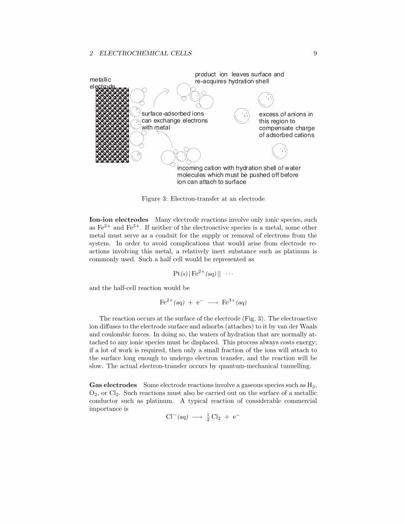
incoming cation with hydration shell of water molecules which must be pushed off before ion can attach to surface
product ion leaves surface and re-acquires hydration shell
AAAAAAA
surface-adsorbed ions can exchange electrons with metal
metallic electrode
excess of anions in this region to compensate charge of adsorbed cations
Figure 3: Electron-transfer at an electrode
Ion-ion electrodes Many electrode reactions involve only ionic species, suchas Fe2+ and Fe3+. If neither of the electroactive species is a metal, some othermetal must serve as a conduit for the supply or removal of electrons from thesystem. In order to avoid complications that would arise from electrode re-actions involving this metal, a relatively inert substance such as platinum iscommonly used. Such a half cell would be represented as
Pt(s) |Fe2+(aq) || · · ·
and the half-cell reaction would be
Fe2+(aq) + e− −→ Fe3+(aq)
The reaction occurs at the surface of the electrode (Fig. 3). The electroactiveion diffuses to the electrode surface and adsorbs (attaches) to it by van der Waalsand coulombic forces. In doing so, the waters of hydration that are normally at-tached to any ionic species must be displaced. This process always costs energy;if a lot of work is required, then only a small fraction of the ions will attach tothe surface long enough to undergo electron transfer, and the reaction will beslow. The actual electron-transfer occurs by quantum-mechanical tunnelling.
Gas electrodes Some electrode reactions involve a gaseous species such as H2,O2, or Cl2. Such reactions must also be carried out on the surface of a metallicconductor such as platinum. A typical reaction of considerable commercialimportance is
Cl−(aq) −→ 12 Cl2 + e−
3 STANDARD HALF-CELL POTENTIALS 10
Similar reactions involving the oxidation of Br2(l) or I2(s) also take place atplatinum surfaces.
Insoluble-salt electrodes A typical electrode of this kind consists of a silverwire covered with a thin coating of silver chloride, which is insoluble in water.The electrode reaction consists in the oxidation and reduction of the silver:
AgCl(s) + e− −→ Ag(s) + Cl−(aq)
The half cell would be represented as
· · · || Cl−(aq) |AgCl(s) |Ag(s)
Although the usefulness of such an electrode may not be immediately apparent,this kind of electrode finds very wide application in electrochemical measure-ments, as we shall see later.
3 Standard half-cell potentials
Although many applications of electrochemical cells involve a flow of currentbetween the two electrodes, the most fundamental kind of measurement we canmake is of the voltage, or EMF between the electrodes in the absence of anycell current. This voltage, which we usually refer to as the cell potential, is thepotential difference between the electrodes, and is the difference between thehalf-cell potentials of the right and left sides:
Ecell = ∆V = Vright − Vleft (2)
Each of the half-cell potentials is in turn a potential difference between theelectrode and the solution, so for our example cell the above relation can beexpanded to
Ecell = VCu − Vsoln + Vsoln − VZn (3)
It is important to understand that individual half-cell potentials are not directlymeasurable; there is no way you can determine the potential difference between apiece of metal and a solution. Attaching one lead of a voltmeter to the metal anddipping the other in the solution would simply create a new half-cell involvingthe immersed metallic conductor.
The fact that individual half-cell potentials are not directly measurable doesnot prevent us from defining and working with them. If we cannot determine theabsolute value of a half-cell potential, we can still measure its value in relationto the potentials of other half cells. In particular, if we adopt a reference half-cell whose potential is arbitrarily defined as zero, and measure the potentialsof various other electrode systems against this reference cell, we are in effect
3 STANDARD HALF-CELL POTENTIALS 11
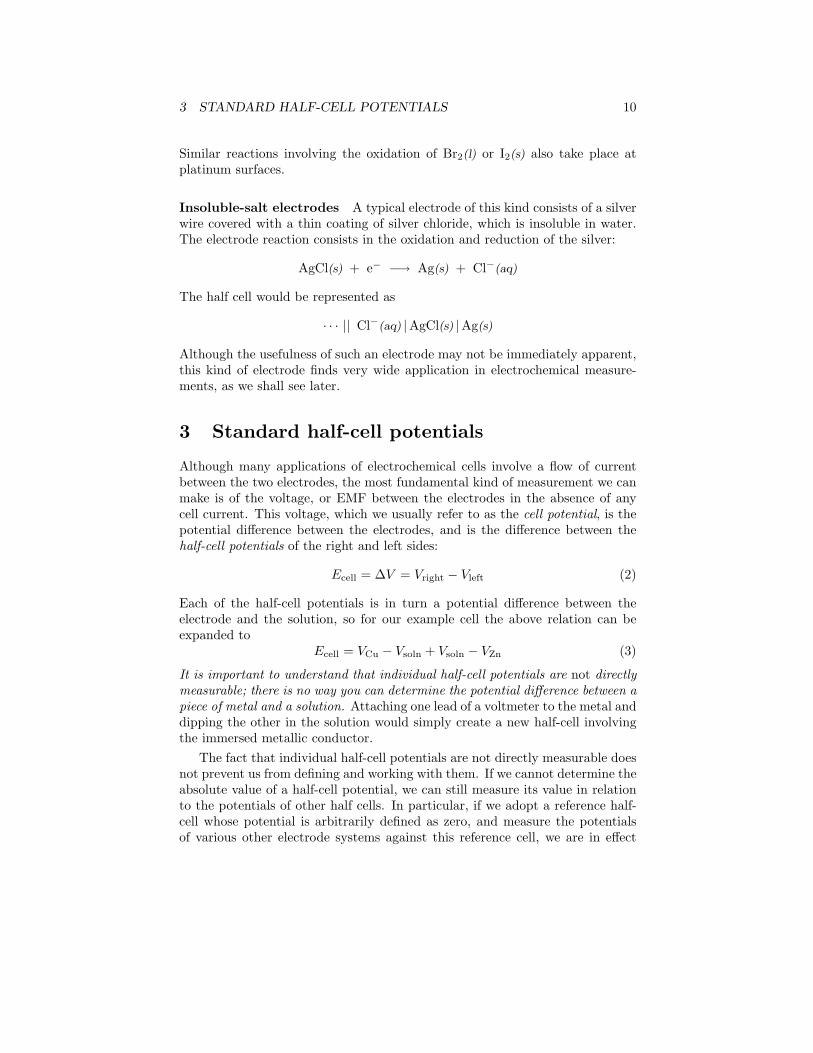
H2
H2
Platinum sheet coated with colloidal Pt
standard hydrogen reference electrode
test cellsalt bridge containing
saturated KCl
potential difference
Figure 4: Cell for measurement of standard potentials
measuring the half-cell potentials on a scale that is relative to the potential ofthe reference cell.
As a reference cell we use the half cell whose reaction is
12 H2(g) −→ H+ + e− (4)
This is the hydrogen electrode, an example of a gas electrode as was discussedabove. When this electrode is set up under standardized conditions, it becomesthe standard hydrogen electrode, sometimes abbreviated SHE.
In order to measure the relative potential of some other electrode M2+/M,we can set up a cell
Pt |H2(g) |H+(aq) || M2+(aq) |M(s) (5)
whose net reaction is
H2(g) + M2+ −→ 2 H+ + M(s)
In analogy with Eq 3, the potential difference between the platinum and Melectrodes will be
Ecell = VM − Vsoln + Vsoln − VPt
3 STANDARD HALF-CELL POTENTIALS 12
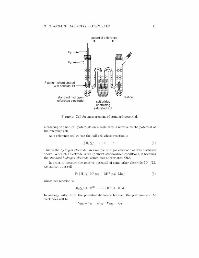
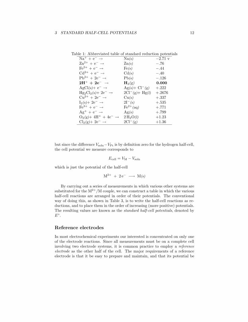
Table 1: Abbreviated table of standard reduction potentialsNa+ + e− → Na(s) −2.71 vZn2+ + e− → Zn(s) −.76Fe2+ + e− → Fe(s) −.44Cd2+ + e− → Cd(s) −.40Pb2+ + 2e− → Pb(s) −.1262H+ + 2e− → H2(g) 0.000AgCl(s)+ e− → Ag(s)+ Cl−(g) +.222Hg2Cl2(s)+ 2e− → 2Cl−(g)+ Hg(l) +.2676Cu2+ + 2e− → Cu(s) +.337I2(s)+ 2e− → 2I−(s) +.535Fe3+ + e− → Fe2+(aq) +.771Ag+ + e− → Ag(s) +.799O2(g)+ 4H+ + 4e− → 2 H2O(l) +1.23Cl2(g)+ 2e− → 2Cl−(g) +1.36
but since the difference Vsoln−VPt is by definition zero for the hydrogen half-cell,the cell potential we measure corresponds to
Ecell = VM − Vsoln
which is just the potential of the half-cell
M2+ + 2 e− −→ M(s)
By carrying out a series of measurements in which various other systems aresubstituted for the M2+/M couple, we can construct a table in which the varioushalf-cell reactions are arranged in order of their potentials. The conventionalway of doing this, as shown in Table 3, is to write the half-cell reactions as re-ductions, and to place them in the order of increasing (more positive) potentials.The resulting values are known as the standard half-cell potentials, denoted byE◦.
Reference electrodes
In most electrochemical experiments our interested is concentrated on only oneof the electrode reactions. Since all measurements must be on a complete cellinvolving two electrode systems, it is common practice to employ a referenceelectrode as the other half of the cell. The major requirements of a referenceelectrode is that it be easy to prepare and maintain, and that its potential be
3 STANDARD HALF-CELL POTENTIALS 13
AAA
AAHg - Hg2Cl2 mixture
saturated KCl solution
glass frit
KCl crystals
fiber wick for contact with external solution
KCl solution
Ag wire coated with AgCl
fiber wick for contact with external solution
saturated calomel electrode
silver-silver chloride electrode
AAAAAAAAAAAAAAAAAAAAAAAAAAA
AAAAAAAAAAAAAAAAAAAAA
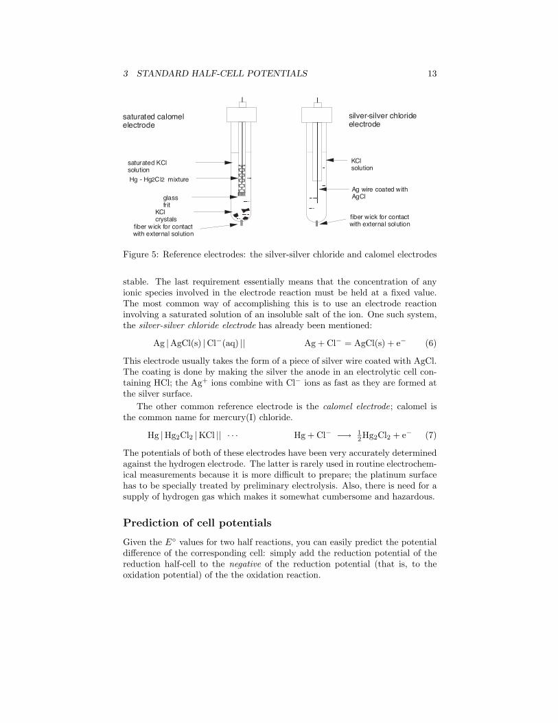
Figure 5: Reference electrodes: the silver-silver chloride and calomel electrodes
stable. The last requirement essentially means that the concentration of anyionic species involved in the electrode reaction must be held at a fixed value.The most common way of accomplishing this is to use an electrode reactioninvolving a saturated solution of an insoluble salt of the ion. One such system,the silver-silver chloride electrode has already been mentioned:
Ag |AgCl(s) |Cl−(aq) || Ag + Cl− = AgCl(s) + e− (6)
This electrode usually takes the form of a piece of silver wire coated with AgCl.The coating is done by making the silver the anode in an electrolytic cell con-taining HCl; the Ag+ ions combine with Cl− ions as fast as they are formed atthe silver surface.
The other common reference electrode is the calomel electrode; calomel isthe common name for mercury(I) chloride.
Hg |Hg2Cl2 |KCl || · · · Hg + Cl− −→ 12Hg2Cl2 + e− (7)
The potentials of both of these electrodes have been very accurately determinedagainst the hydrogen electrode. The latter is rarely used in routine electrochem-ical measurements because it is more difficult to prepare; the platinum surfacehas to be specially treated by preliminary electrolysis. Also, there is need for asupply of hydrogen gas which makes it somewhat cumbersome and hazardous.
Prediction of cell potentials
Given the E◦ values for two half reactions, you can easily predict the potentialdifference of the corresponding cell: simply add the reduction potential of thereduction half-cell to the negative of the reduction potential (that is, to theoxidation potential) of the the oxidation reaction.
3 STANDARD HALF-CELL POTENTIALS 14
Problem Example 2Find the standard potential of the cell
Cu(s) |Cu2+ || Cl− |AgCl(s) |Ag(s)
and predict the direction of electron flow when the two electrodes areconnected. Solution. The net reaction corresponding to this cell will be
2 Ag(s) + 2 Cl−(aq) + Cu2+(aq) −→ AgCl(s) + Cu(s)
Since this involves the reverse of the AgCl reduction, we must reverse thecorresponding half-cell potential:
Ecell = (.337− .222) v = .115 v
Since this potential is positive, then the reaction will proceed to the
right, and electrons will be withdrawn from the copper electrode and
flow through the external circuit into the silver electrode. Note carefully
that in combining these half-cell potentials, we did not multiply the E◦
for the Cu2+/Cu couple by two. The reason for this will be explained later.
Cell potentials and the electromotive series
The remarkable thing about Table 3 is that similar tables, containing the samesequence of reactions, were in common use long before electrochemical cells werestudied and half-cell potentials had been measured. If you read down the centralcolumn, you will notice that it begins with the sequence of metals Na, Zn, Fe,etc. This sequence is known as the activity series of the metals, and expressesthe decreasing tendency of the species listed in this column to lose electrons–that is, to undergo oxidation.
The activity series has long been used to predict the direction of oxidation-reduction reactions. Consider, for example, the oxidation of Cu2+ by metalliczinc that we have mentioned previously. The fact that zinc is near the top ofthe activity series means that this metal has a strong tendency to lose electrons.By the same token, the tendency of Zn2+ to accept electrons is relatively small.Copper, on the other hand, is a poorer electron donor, and thus its oxidizedform, Cu2+, is a fairly good electron acceptor. We would therefore expect thereaction
Zn(s) + Cu2+ −→ Zn2+ + Cu(s)
to proceed in the direction indicated, rather than in the reverse direction. Anold-fashioned way of expressing this is to say that “zinc will displace copperfrom solution”.
The presence of the half-cell potentials in Table 3 allows us to attach numbersto our predictions. As was implied in the preceding problem example, if the
3 STANDARD HALF-CELL POTENTIALS 15
potential of a cell made up of the two half-cell reactions is positive, then thereaction will proceed spontaneously to the right; if it is negative, the reversereaction will be spontaneous.
Cell potentials and free energy
From the above, it should be apparent that the potential difference between theelectrodes of a cell is a measure of the tendency for the cell reaction to take place:the more positive the cell potential, the greater the tendency for the reactionto proceed to the right. But we already know that the standard free energychange, ∆G◦, expresses the tendency for any kind of process to occur under theconditions of constant temperature and pressure. Thus E◦and ∆G◦measure thesame thing, and are related in a simple way:
∆G◦ = −nFE◦ (8)
A few remarks are in order about this very fundamental and important relation:
• The negative sign on the right indicates that a positive cell potential (ac-cording to the sign convention discussed previously) implies a negative freeenergy change, and thus that the cell reaction will proceed to the right.
• Electrical work is done when an electric charge q moves through a potentialdifference ∆V . The right side of Eq 8 refers to the movement of n moles ofcharge across the cell potential E◦, and thus has the dimensions of work.
• The Gibbs function is more than a criterion for spontaniety; the valueof ∆G◦ expresses the maximum useful work that a system can do on thesurroundings. “Useful” here means work other than P-V work that issimply a consequence of volume change, which cannot be channelled tosome practical use. This maximum work can only be extracted from thesystem under the limiting conditions of a reversible change, which foran electrochemical cell, implies zero current. The more rapidly the celloperates, the less electrical work it can supply.
• If F is expressed in coulombs per mole, the electrical work ∆G◦ is in joulesper mole. To relate these units to electrical units, recall that the coulombis one amp-sec, and that power, which is the rate at which work is done,is measured in watts, which is the product of amps and volts. Thus
1 J = 1 watt-sec = 1 (amp-sec) × volts
Problem Example 3For how many minutes could a Cu/Zn cell keep a 100-watt lamp lit, as-suming that one mole of reactants are transformed to products, and thatthe cell voltage is 90 percent of the reversible value E◦?
3 STANDARD HALF-CELL POTENTIALS 16
Solution. From Table 3, E◦ for the cell
Zn(s) |Zn2+(aq) || Cu2+(aq) |Cu(s)
is 1.10 v; 90% of this is 1.0 v. Substituting into Eq 8 with n = 2 (twoelectrons are transferred per mole of reaction), we have
−(2 mol)× (96500 amp-sec mol−1)× 1.0 volt = −212000 watt-sec
which is also the free energy change under these conditions. The cell can
deliver 100 watts for (212000/100) = 100 sec, or for about 35 minutes.
If Eq 8 is solved for E◦, we have
E◦ = −∆G◦
nFThis explains why we do not have to multiply the E◦s of half reactions bystoichiometric factors when we are finding the E◦ of a complete cell; since n isin the denominator, we can think of cell potentials as free energy changes permole of charge transferred.
To see this, consider the cell
Cu(s) |Cu2+ || Cl− |AgCl(s) |Ag(s)
for which we list the potentials and ∆G◦s of the half-reactions:
reaction E◦ −nFE◦ = ∆G◦
AgCl(s) + e− −→ Ag(s) + Cl− +.222 v −42800 JCu(s) −→ Cu2+ + 2e− −(+.337) v +65000 J
2 Ag(s) + 2 Cl−(aq) + Cu2+(aq) −→ AgCl(s) + Cu(s) −.115 v +22200 J
Note, however, that if we are combining two half reactions to obtain a thirdhalf reaction, the E◦ values are not additive, since we are not eliminating elec-trons. Free energies are always additive, so we combine them, and use Eq 8 tofind the cell potential.
Problem Example 4Calculate E◦ for the electrode Fe3+/Fe from E◦ values for Fe3+/Fe2+ andFe2+/Fe.
Solution. Tabulate the E◦ values and calculate the ∆G◦s as follows:
Fe3+ + e− −→ Fe2+ Eo1 = .771 v ∆G◦1 = −.771 FFe2+ + 2 e− −→ Fe(s) E◦2 = −.440 v ∆G◦2 = +.880FFe3+ + 3 e− −→ Fe(s) E◦3 = ? .109 F
The free energy for the net half-reaction is .109nF , so E◦3 = −.109/3 =
−.036 v.
3 STANDARD HALF-CELL POTENTIALS 17
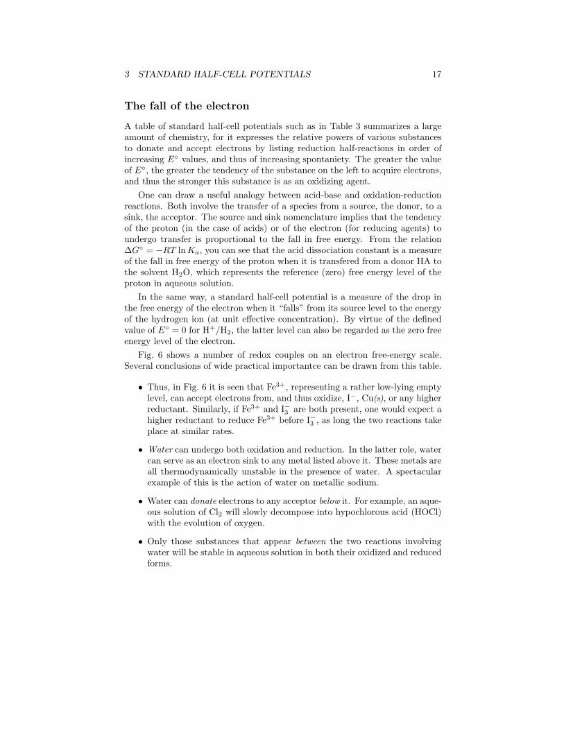
The fall of the electron
A table of standard half-cell potentials such as in Table 3 summarizes a largeamount of chemistry, for it expresses the relative powers of various substancesto donate and accept electrons by listing reduction half-reactions in order ofincreasing E◦ values, and thus of increasing spontaniety. The greater the valueof E◦, the greater the tendency of the substance on the left to acquire electrons,and thus the stronger this substance is as an oxidizing agent.
One can draw a useful analogy between acid-base and oxidation-reductionreactions. Both involve the transfer of a species from a source, the donor, to asink, the acceptor. The source and sink nomenclature implies that the tendencyof the proton (in the case of acids) or of the electron (for reducing agents) toundergo transfer is proportional to the fall in free energy. From the relation∆G◦ = −RT lnKa, you can see that the acid dissociation constant is a measureof the fall in free energy of the proton when it is transfered from a donor HA tothe solvent H2O, which represents the reference (zero) free energy level of theproton in aqueous solution.
In the same way, a standard half-cell potential is a measure of the drop inthe free energy of the electron when it “falls” from its source level to the energyof the hydrogen ion (at unit effective concentration). By virtue of the definedvalue of E◦ = 0 for H+/H2, the latter level can also be regarded as the zero freeenergy level of the electron.
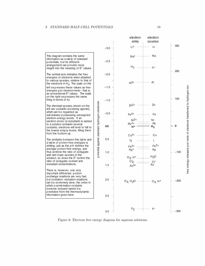
Fig. 6 shows a number of redox couples on an electron free-energy scale.Several conclusions of wide practical importantce can be drawn from this table.
• Thus, in Fig. 6 it is seen that Fe3+, representing a rather low-lying emptylevel, can accept electrons from, and thus oxidize, I−, Cu(s), or any higherreductant. Similarly, if Fe3+ and I−3 are both present, one would expect ahigher reductant to reduce Fe3+ before I−3 , as long the two reactions takeplace at similar rates.
• Water can undergo both oxidation and reduction. In the latter role, watercan serve as an electron sink to any metal listed above it. These metals areall thermodynamically unstable in the presence of water. A spectacularexample of this is the action of water on metallic sodium.
• Water can donate electrons to any acceptor below it. For example, an aque-ous solution of Cl2 will slowly decompose into hypochlorous acid (HOCl)with the evolution of oxygen.
• Only those substances that appear between the two reactions involvingwater will be stable in aqueous solution in both their oxidized and reducedforms.
3 STANDARD HALF-CELL POTENTIALS 18
Ð2.5
3.0
Ð2.0
Ð1.5
Ð1.0
Ð0.5
0.0
0.5
1.0
1.5
Ð3.0
2.0
2.5
300
200
100
0
Ð100
Ð200
Li
Na
Al
Zn
Fe
NiPbH2
Cu
I
Fe2+
Ag
H2O
ClÐ
O3, H+
FÐ
Li+
Na+
H2 HÐ
Al3+
Zn2+
Ni2+
Pb 2+
H+
Cu2+
O2, H2O
I2
Fe3+
O2, H+
Cl2Au3+ Au
F2
Fe2+
po
tent
ial a
gai
nst
stan
dar
d h
ydro
ge
n e
lect
rod
e
fre
e e
nerg
y re
leas
ed
pe
r m
ole
of
ele
ctro
ns t
rans
ferr
ed
to
hyd
rog
en
ion
electron sources
electron sinks
Ð300
Ag+
This diagram contains the same information as a tab le of standard p otentials, b ut its different arrangement can p rovide more insight into the meaning of E¡ values.
The vertical axis indicates the free energies of electrons when attached to various sp ecies, relative to that of the electrons in H2. The scale on the left exp resses these values as free energies p er electron-moleÐ that is, as conventional E¡ values. The scale on the right exp resses the same thing in terms of kJ.
The chemical sp ecies shown on the left are oxidants (oxidizing agents), which can b e regarded as sub stances p ossessing unoccup ied electron energy levels. If an electron donor (a reductant) is added to a solution containin several oxidants, electrons will tend to fall to the lowest emp ty levels, filling them from the b ottom up .
The similarity b etween this tab le and a tab le of p roton free energies is striking; just as the p H defines the average p roton free energy, and thus controls the ratio of conjugate acid and b ase sp ecies in the solution, so does the E¡ control the ratio of conjugate oxidant and reductant concentrations.
There is, however, one very imp ortant difference: p roton-exchange reactions are very fast, b ut oxidation -reduction reactions can b e extremely slow, the order in which a comb ination oxidants b ecome reduced cannot b e p redicted from the thermodynamic information given here.
Figure 6: Electron free energy diagram for aqueous solutions.

3 STANDARD HALF-CELL POTENTIALS 19
• A metal that is above the H+/H2 couple will react with acids, liberatingH2; these are sometimes known as the “active” metals. Such metals willalso of course react with water.
3 STANDARD HALF-CELL POTENTIALS 20
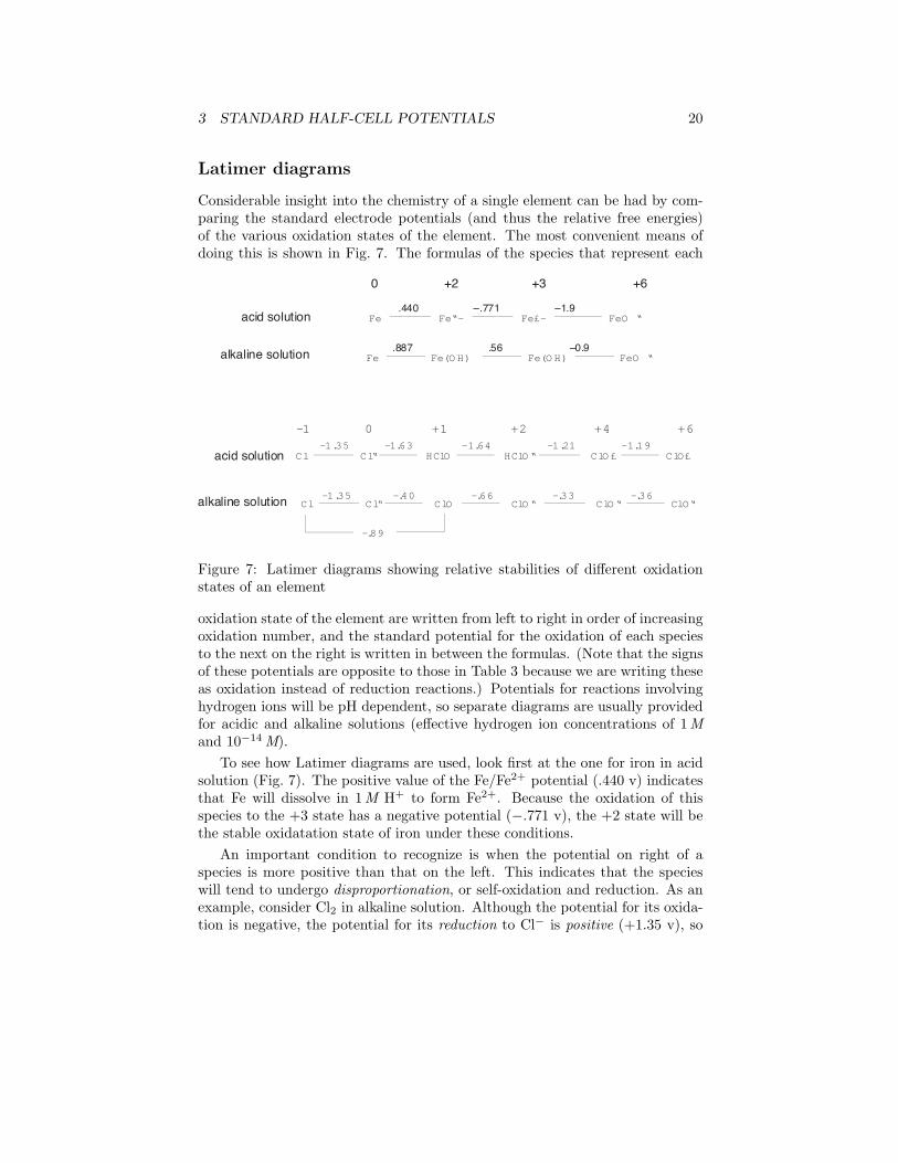
Latimer diagrams
Considerable insight into the chemistry of a single element can be had by com-paring the standard electrode potentials (and thus the relative free energies)of the various oxidation states of the element. The most convenient means ofdoing this is shown in Fig. 7. The formulas of the species that represent each
Fe Fe“– Fe£– FeO “.440 Ð.771 Ð1.9
Fe Fe(O H) Fe(O H) FeO “.887 .56 Ð0.9
0 +2 +3 +6
acid solution
alkaline solution
Cl Cl“ HClO HClO “ ClO £ ClO£—1.35 —1.63 —1.64 —1.21 —1.19
Cl Cl“ ClO ClO “ ClO “ ClO“—1.35 —.40 —.66 —.33 —.36
—.89
—1 0 +1 +2 +4 +6
acid solution
alkaline solution
Figure 7: Latimer diagrams showing relative stabilities of different oxidationstates of an element
oxidation state of the element are written from left to right in order of increasingoxidation number, and the standard potential for the oxidation of each speciesto the next on the right is written in between the formulas. (Note that the signsof these potentials are opposite to those in Table 3 because we are writing theseas oxidation instead of reduction reactions.) Potentials for reactions involvinghydrogen ions will be pH dependent, so separate diagrams are usually providedfor acidic and alkaline solutions (effective hydrogen ion concentrations of 1 Mand 10−14 M).
To see how Latimer diagrams are used, look first at the one for iron in acidsolution (Fig. 7). The positive value of the Fe/Fe2+ potential (.440 v) indicatesthat Fe will dissolve in 1 M H+ to form Fe2+. Because the oxidation of thisspecies to the +3 state has a negative potential (−.771 v), the +2 state will bethe stable oxidatation state of iron under these conditions.
An important condition to recognize is when the potential on right of aspecies is more positive than that on the left. This indicates that the specieswill tend to undergo disproportionation, or self-oxidation and reduction. As anexample, consider Cl2 in alkaline solution. Although the potential for its oxida-tion is negative, the potential for its reduction to Cl− is positive (+1.35 v), so
4 THE NERNST EQUATION 21
the free energy necessary for the oxidation of one atom of chlorine to hypochlo-rite can be supplied by the reduction of another to chloride ion. Thus elementalchlorine is thermodynamically unstable with respect to disproportionation inalkaline solution, and the same it true of the oxidation product, HClO−.
This might be a good time to point out that many oxidation-reduction re-actions, unlike most acid-base reactions, tend to be very slow, so the fact that aspecies is thermodynamically unstable does not always mean that it will quicklydecompose. Thus the disproportionion of chlorine mentioned above occurs onlyvery slowly. Interestingly, this process is catalyzed by light, and this is whyextra chlorine has to be used to disinfect outdoor swimming pools on sunnydays.
4 The Nernst equation
The standard cell potentials we have been discussing refer to cells in which alldissolved substances are at unit activity, which essentially means an “effectiveconcentration” of 1 M. Similarly, any gases that take part in an electrode re-action are at an effective pressure (known as the fugacity) of 1 atm. If theseconcentrations or pressures have other values, the cell potential will change ina manner that can be predicted from the principles you already know.
Suppose, for example, that we reduce the concentration of Zn2+ in the Zn/Cucell from its unit-activity value of around .5 M to a much smaller value:
Zn(s) |Zn2+((aq), 0.001 M ) || Cu2+(aq) |Cu(s)
This will reduce the value of Q for the cell reaction
Zn(s) + Cu2+ −→ Zn2+ + Cu(s)
thus making it more spontaneous, or “driving it to the right” as the Le Chatelierprinciple would predict, and making its free energy change ∆G more negativethan ∆G◦, so that E would be more positive than E◦.
The relation between the actual cell potential E and the standard potentialE◦ is developed in the following way. First, we can use Eq 8 to express ∆G aswell as ∆G◦:
∆G◦ = −nFE◦(8) (9)
∆G = −nFE (10)
These expressions can then be substituted into the relation
∆G = ∆G◦ +RT lnQ
which gives−nFE = −nFE◦ +RT lnQ
4 THE NERNST EQUATION 22
E given by Nernst Equation
Measured value of E
E�
-4 -3 -2 -1 0
log concentration of Ag+
slope 0.059
E of Ag+/Ag half-cell .059 volt
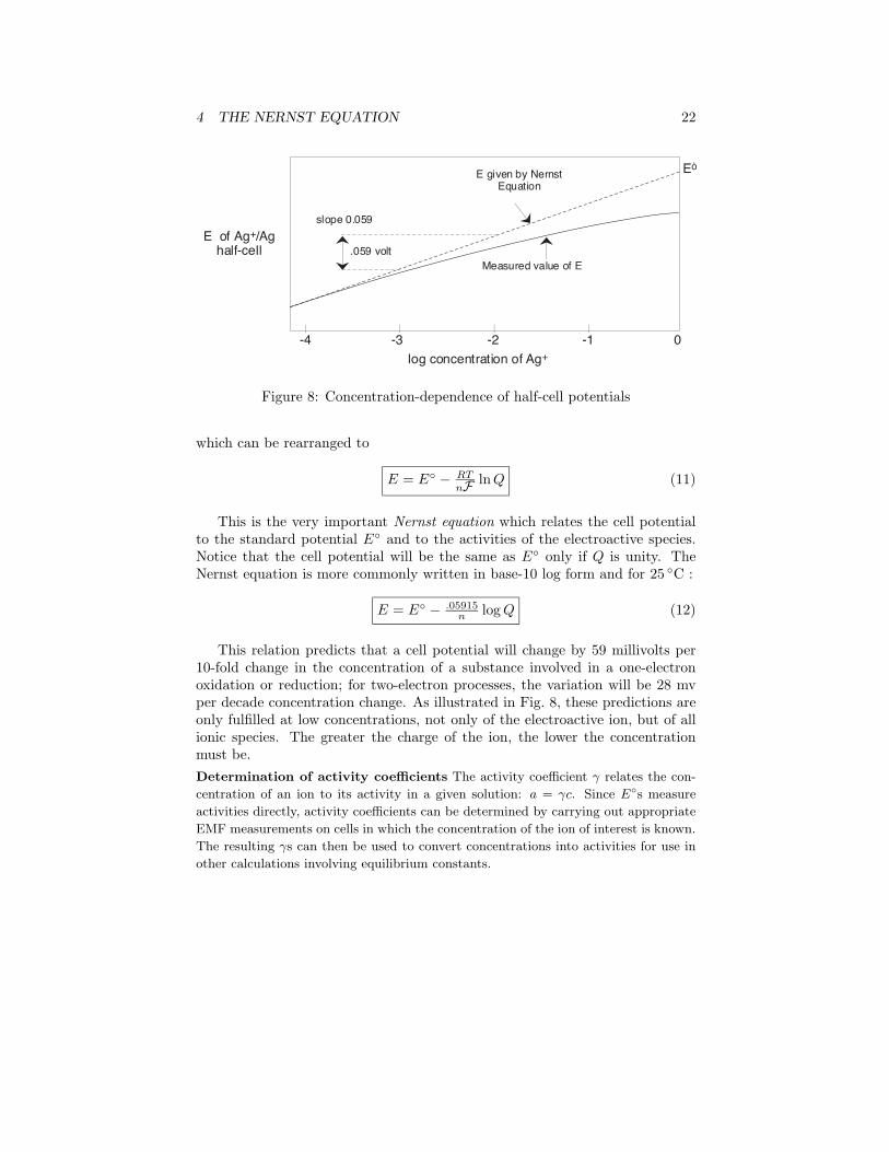
Figure 8: Concentration-dependence of half-cell potentials
which can be rearranged to
E = E◦ − RT
nF lnQ (11)
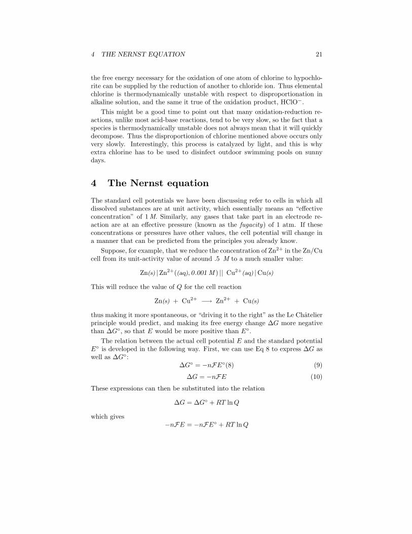
This is the very important Nernst equation which relates the cell potentialto the standard potential E◦ and to the activities of the electroactive species.Notice that the cell potential will be the same as E◦ only if Q is unity. TheNernst equation is more commonly written in base-10 log form and for 25 ◦C :
E = E◦ − .05915n logQ (12)
This relation predicts that a cell potential will change by 59 millivolts per10-fold change in the concentration of a substance involved in a one-electronoxidation or reduction; for two-electron processes, the variation will be 28 mvper decade concentration change. As illustrated in Fig. 8, these predictions areonly fulfilled at low concentrations, not only of the electroactive ion, but of allionic species. The greater the charge of the ion, the lower the concentrationmust be.Determination of activity coefficients The activity coefficient γ relates the con-
centration of an ion to its activity in a given solution: a = γc. Since E◦s measure
activities directly, activity coefficients can be determined by carrying out appropriate
EMF measurements on cells in which the concentration of the ion of interest is known.
The resulting γs can then be used to convert concentrations into activities for use in
other calculations involving equilibrium constants.
4 THE NERNST EQUATION 23
Concentration cells
From your study of thermodynamics you may recall that the process
solute(concentrated) −→ solute(dilute)
is accompanied by a fall in free energy, and therefore is capable of doing workon the surroundings; all that is required is some practical way of capturing thiswork. One way of doing this is by means of a concentration cell such as
Cu(s) |CuNO3(.1 M ) || CuNO3(.01 M ) |Cu(s) (13)
The electrode cell reactions are
cathode: Cu2+(.1 M ) + 2 e− −→ Cu(s)
anode: Cu(s) −→ + 2 e− + Cu2+(.01 M )net reaction: Cu2+(.1 M ) −→ Cu2+(.01 M )
which represents the transport of cupric ion from a region of higher concentra-tion to one of lower concentration. The Nernst equation for this cell is
E = E◦ − .05915n
logQ = 0− .0295 log .1 = +.0285 v
Note that E◦ for a concentration cell is always zero, since this would bethe potential of a cell in which both solutes have the same (standard) effectiveconcentration of unity.
Analytical applications of the Nernst equation
A very large part of Chemistry is concerned, either directly or indirectly, withdetermining the concentrations of ions in solution. Any method that can accom-plish such measurements using relatively simple physical techniques is bound tobe widely exploited. Cell potentials are fairly easy to measure, and although theNernst equation relates them to ionic activities rather than to concentrations,the difference between them becomes negligible in solutions where the total ionicconcentration is less than about 10−3 M.
Determination of solubility products
The concentrations of ions in equilibrium with a sparingly soluble salt are suffi-ciently low that the Nernst equation can be used with little error. Rather thanmeasuring the concentration of the relevant ions directly, the more commonprocedure is to set up a cell in which one of the electrodes involves the insolublesalt, and whose net cell reaction is just the dissolution of the salt. For example,to determine the Ksp for silver chloride, we could use the electrode of Eq 6 inthe cell
Ag(s) |Ag+ ? M || Ag+,Cl− |AgCl(s) |Ag(s)
4 THE NERNST EQUATION 24
AgCl(s) + e− −→ Ag(s) + Cl−(aq) E◦ = +.222 vAg(s) −→ Ag+(aq) + e− −E◦ =-(+.799)vAgCl(s) −→ Ag+ + Cl−
Potentiometric titrations
In many situations, accurate determination of an ion concentration by directmeasurement of a cell potential is impossible due to the presence of other ionsand a lack of information about activity coefficients. In such cases it is oftenpossible to determine the ion indirectly by titration with some other ion. Forexample, the initial concentration of an ion such as Fe2+ can be found by titrat-ing with a strong oxidizing agent such as Ce4+. The titration is carried out inone side of a cell whose other half is a reference electrode:
Pt(s) |Fe2+,Fe3+ || reference electrode
Initially the left cell contains only Fe2+. As the titrant Ce4+ is added, theferrous ion is oxidized to Fe3+in a reaction that is virtually complete:
Fe2+ + Ce4+ −→ Fe3+ + Ce3+
The cell potential is followed as the Fe2+ is added in small increments. Oncethe first drop of Ce3+ has been added, the potential of the left cell is controlledby the ratio of oxidized and reduced iron according to the Nernst equation
E = .68− .059 log[Fe2+][Fe3+]
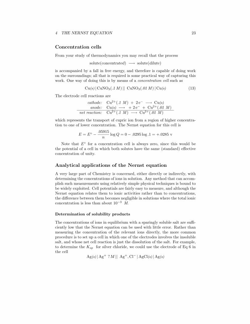
When the equivalence point is reached, the Fe2+will have been totally consumed(the large equilibrium constant ensures that this will be so), and the potentialwill then be controlled by the concentration ratio of Ce3+/Ce4+. The idea is thatboth species of a redox couple must be present in reasonable concentrations for aconcentration to control the potential of an electrode of this kind. If one worksout the actual cell potentials for various concentrations of all these species, theresulting titration curve (Fig. 9) looks much like the familiar acid-base titrationcurve. The end point is found not by measuring a particular cell voltage, butby finding what volume of titrant gives the steepest part of the curve.
Measurement of pH
Since pH is actually defined in terms of hydrogen ion activity and not its con-centration, a hydrogen electrode allows a direct measure of aH+ and thus of− log aH+ , which is the pH.
H2(g , 1atm) |Pt |H+(? M) || reference electrode
4 THE NERNST EQUATION 25
0 10 20 30
1.2
1.0
0.8
0.6
0.4
potential against standard calomel electrode (volts)
volume of Ce4+ solution added
At the end point, there is no more Fe2+, so the potential rises rapidly to that of a Ce4+/Ce3+ cell with excess Ce4+.
Initially, the solution is mostly Fe2+. As Ce4+ is added, the iron is oxidized and the potential slowly rises as the Fe2+/Fe3+ ratio decreases.
Figure 9: Curve for the potentiometric titration of FeSO4 with Ce(SO4)2
AAAAAAAAAA
Ag wire coated with AgClHCl solutionthin glass membrane
AAAAAAAA
AAAAAAAA
AAAAAAAA
AAAA
AAAAAAAA
AAAAAAAA
internal soution
external (test) solution
glass hydration gel layers
0.1mm glass membranewith exchangeable Na+ ions
AAAAAAAAAAAAAAAAAAAA
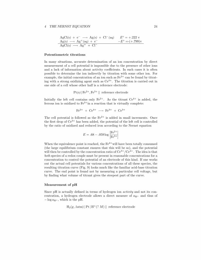
Figure 10: The glass electrode for pH measurements
Although this arrangement (in which the reference electrode could be a standardhydrogen electrode) has been used for high-precision determinations, it wouldbe impractical for routine pH measurements of the kinds that are widely done,especially outside the laboratory.
In 1914 it was discovered that a thin glass membrane enclosing a solutionof HCl can produce a potential that varies with [H+] in about the same wayas that of the hydrogen electrode. Glass electrodes (Fig. 10) are manufacturedin huge numbers for both laboratory and field measurements. They contain abuilt-in Ag-AgCl reference electrode in contact with the HCl solution enclosedby the membrane.
The potential of a glass electrode is given by a form of the Nernst equationvery similar to that of an ordinary hydrogen electrode, but of course without
4 THE NERNST EQUATION 26
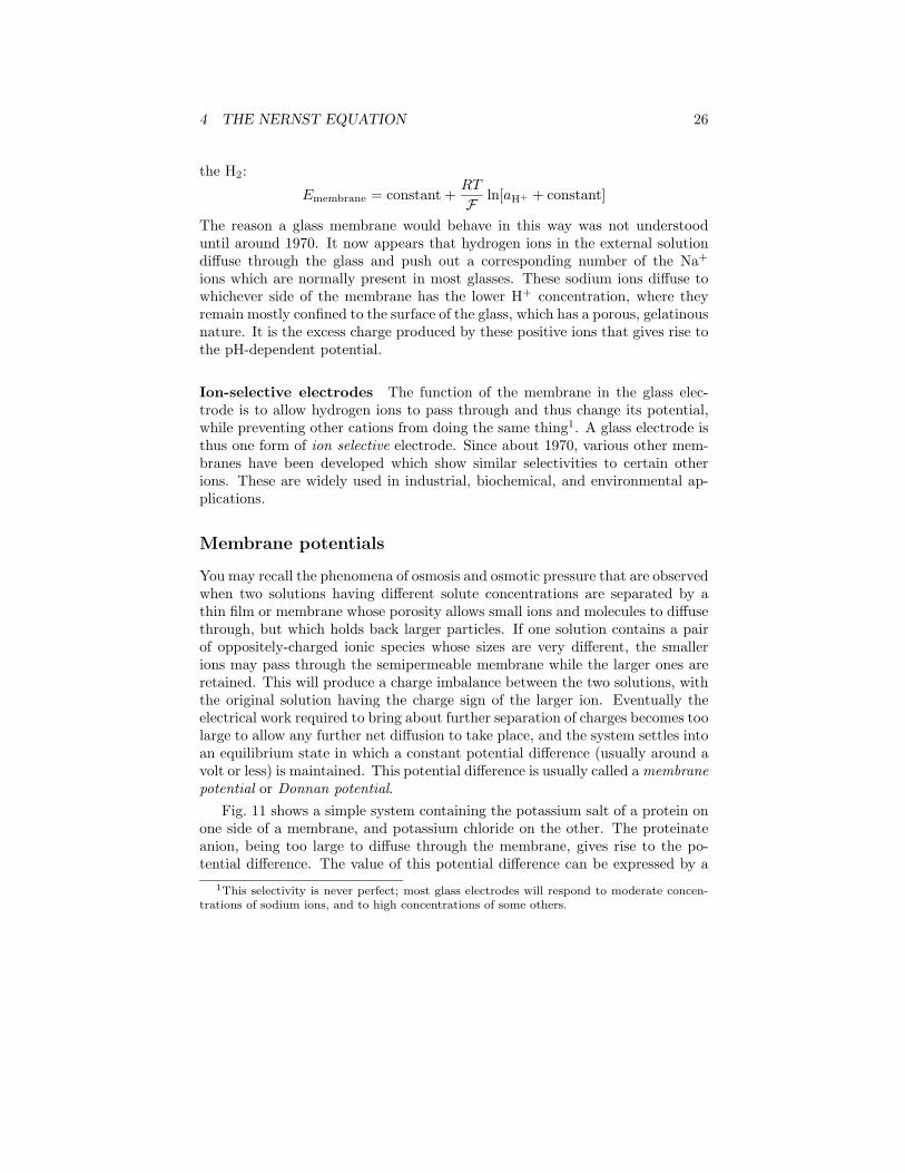
the H2:
Emembrane = constant +RT
F ln[aH+ + constant]
The reason a glass membrane would behave in this way was not understooduntil around 1970. It now appears that hydrogen ions in the external solutiondiffuse through the glass and push out a corresponding number of the Na+
ions which are normally present in most glasses. These sodium ions diffuse towhichever side of the membrane has the lower H+ concentration, where theyremain mostly confined to the surface of the glass, which has a porous, gelatinousnature. It is the excess charge produced by these positive ions that gives rise tothe pH-dependent potential.
Ion-selective electrodes The function of the membrane in the glass elec-trode is to allow hydrogen ions to pass through and thus change its potential,while preventing other cations from doing the same thing1. A glass electrode isthus one form of ion selective electrode. Since about 1970, various other mem-branes have been developed which show similar selectivities to certain otherions. These are widely used in industrial, biochemical, and environmental ap-plications.
Membrane potentials
You may recall the phenomena of osmosis and osmotic pressure that are observedwhen two solutions having different solute concentrations are separated by athin film or membrane whose porosity allows small ions and molecules to diffusethrough, but which holds back larger particles. If one solution contains a pairof oppositely-charged ionic species whose sizes are very different, the smallerions may pass through the semipermeable membrane while the larger ones areretained. This will produce a charge imbalance between the two solutions, withthe original solution having the charge sign of the larger ion. Eventually theelectrical work required to bring about further separation of charges becomes toolarge to allow any further net diffusion to take place, and the system settles intoan equilibrium state in which a constant potential difference (usually around avolt or less) is maintained. This potential difference is usually called a membranepotential or Donnan potential.
Fig. 11 shows a simple system containing the potassium salt of a protein onone side of a membrane, and potassium chloride on the other. The proteinateanion, being too large to diffuse through the membrane, gives rise to the po-tential difference. The value of this potential difference can be expressed by a
1This selectivity is never perfect; most glass electrodes will respond to moderate concen-trations of sodium ions, and to high concentrations of some others.
4 THE NERNST EQUATION 27
AAAAAAAAAAAAAAAA
AAA
membrane
AAAAAAÐ AAAAAA+
AAAAAAAAAAAÐ
Ð +
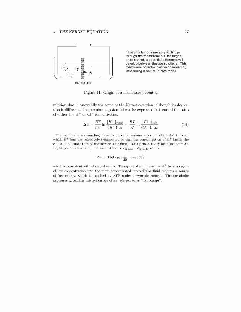
If the smaller ions are able to diffuse through the membrane but the larger ones cannot, a potential difference will develop between the two solutions. This membrane potential can be observed by introducing a pair of Pt electrodes.A AA
AAAAAAAA AAAAAA+
Figure 11: Origin of a membrane potential
relation that is essentially the same as the Nernst equation, although its deriva-tion is different. The membrane potential can be expressed in terms of the ratioof either the K+ or Cl− ion activities:
∆Φ =RT
nF ln{K+}right
{K+}left=RT
nF ln{Cl−}left
{Cl−}right(14)
The membrane surrounding most living cells contains sites or “channels” throughwhich K+ ions are selectively transported so that the concentration of K+ inside thecell is 10-30 times that of the intracellular fluid. Taking the activity ratio as about 20,Eq 14 predicts that the potential difference φinside − φoutside will be
∆Φ = .059 log10
1
20= −70 mV
which is consistent with observed values. Transport of an ion such as K+ from a region
of low concentration into the more concentrated intercellular fluid requires a source
of free energy, which is supplied by ATP under enzymatic control. The metabolic
processes governing this action are often referred to as “ion pumps”.
4 THE NERNST EQUATION 28
AAAAAAAAAAAAAAAAAAAAAAAAAAA
AAAAAAAAAAAAA
AAAAAAAAAAAAA
+� + + + + + + + Ð Ð Ð Ð Ð + + + + + + + + + + + + + + + + + + + + +
+� + + + + + + + Ð Ð Ð Ð Ð + + + + + + + + + + + + + + + + + + + + +
Ð Ð Ð Ð Ð Ð Ð Ð + + + + + Ð Ð Ð Ð Ð Ð Ð Ð Ð Ð Ð Ð Ð Ð Ð Ð Ð Ð Ð Ð Ð
pote
ntia
l , m
v
AAAAAAAAAA
ClÐ
AAAAAAAAAAClÐ
plot of potential difference between inside and outside along nerve fibre
Region of excitation due to influx of Na+ ions travels along nerve
AAAAAAAAAANa+
resting potential restored as ion pumps remove excess Na+
nerve cell wall
nerve cell wall
interior of nerve fibre has excess negative charge in resting state
Ð20
Ð70
0
extracellular fluid
AAAAAAAK+ AAAAAAAK+
AAAAAAAAAAClÐ
AAAAAAANa+
AAAAAAAAAANa+
AAAAAAAAAAK+
Figure 12: Conduction of nerve impulses
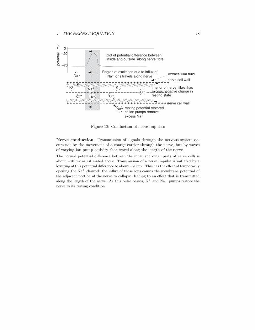
Nerve conduction Transmission of signals through the nervous system oc-curs not by the movement of a charge carrier through the nerve, but by wavesof varying ion pump activity that travel along the length of the nerve.The normal potential difference between the inner and outer parts of nerve cells is
about −70 mv as estimated above. Transmission of a nerve impulse is initiated by a
lowering of this potential difference to about−20 mv. This has the effect of temporarily
opening the Na+ channel; the influx of these ions causes the membrane potential of
the adjacent portion of the nerve to collapse, leading to an effect that is transmitted
along the length of the nerve. As this pulse passes, K+ and Na+ pumps restore the
nerve to its resting condition.
5 BATTERIES AND FUEL CELLS 29
5 Batteries and fuel cells
An electrochemical cell which operates spontaneously can deliver an amount ofwork to the surroundings whose upper limit (in the case of reversible operation)is equal to the fall in free energy as the cell reaction proceeds. In the process,chemical energy is converted into electrical energy, which may in turn be utilizedin a variety of practical ways. As the reaction continues the free energy of thesystem falls, so as time goes by less energy remains to be recovered. Eventuallythe cell reaction comes to equilibrium (∆G= 0) and no further work can beextracted; the cell is “dead”.
A battery is a practical adaptation of this arrangment and usually consists ofa number of cells connected in series so as to attain the desired output voltage.One of the earliest batteries was based on the simple zinc-copper cell of Fig. 2;this was used, among other things, for telegraphy and railroad signalling duringthe nineteenth century, when batteries provided the only practical source ofelectrical power.
Batteries are usually classified as primary or secondary cells. The latteris also called a storage cell, which more aptly describes its ability to convertelectrical energy into chemical energy and then re-supply it as electrical energyon demand. The cell reaction of a storage cell can proceed in either direction;during charging, electrical work is done on the cell to provide the free energyneeded to force the reaction in the non-spontaneous direction. A primary cell,as expemplified by an ordinary flashlight battery, cannot be recharged with anyefficiency, so the amount of energy it can deliver is limited to that obtainablefrom the reactants that were placed in it at the time of manufacture.The most well-known storage cell is the lead-acid cell, which was invented by Plante in1859 and is still the most practical known way of storing large quantities of electricalenergy. The cell is represented by
Pb(s) |PbSO4(s) |H2SO4(aq) |PbSO4(s), PbO2(s) |Pb(s)
and the net cell reaction
Pb(s) + PbO2(s) + 2 H2SO4(aq) −→ 2 PbSO4(s) + 2 H2O
The reaction proceeds to the right during discharge and to the left during charging.
The state of charge can be estimated by measuring the density of the electrolyte;
sulfuric acid is about twice as dense as water, so as the cell is discharged, the density
of the electrolyte decreases.
The fuel cell
Conventional batteries supply electrical energy from the chemical reactantsstored within them; when these reactants are consumed, the battery is “dead”.An alternative approach would be to feed the reactants into the cell as they
5 BATTERIES AND FUEL CELLS 30
AAAAAAAAAAAA
AAAAAAAAAAAA
AAAAAAAAAAAAAAAAAAAAAAAA
H2 fuel O2
water + excess O2
porous anode
porous cathode
electrolyte � H± �
4H+ + O2 + 4eÑ ® 2H2O2H2 ® 4H++ 4eÑ
Ð +
eÑ®
external circuit
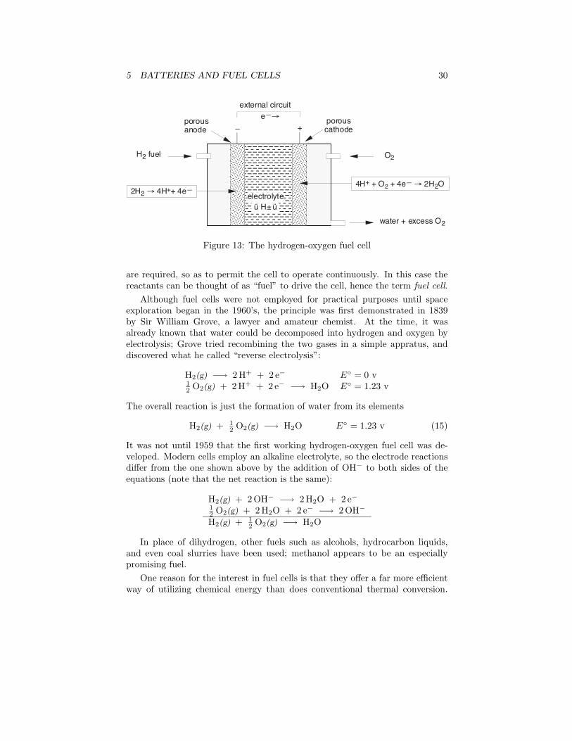
Figure 13: The hydrogen-oxygen fuel cell
are required, so as to permit the cell to operate continuously. In this case thereactants can be thought of as “fuel” to drive the cell, hence the term fuel cell.
Although fuel cells were not employed for practical purposes until spaceexploration began in the 1960’s, the principle was first demonstrated in 1839by Sir William Grove, a lawyer and amateur chemist. At the time, it wasalready known that water could be decomposed into hydrogen and oxygen byelectrolysis; Grove tried recombining the two gases in a simple appratus, anddiscovered what he called “reverse electrolysis”:
H2(g) −→ 2 H+ + 2 e− E◦ = 0 v12 O2(g) + 2 H+ + 2 e− −→ H2O E◦ = 1.23 v
The overall reaction is just the formation of water from its elements
H2(g) + 12 O2(g) −→ H2O E◦ = 1.23 v (15)
It was not until 1959 that the first working hydrogen-oxygen fuel cell was de-veloped. Modern cells employ an alkaline electrolyte, so the electrode reactionsdiffer from the one shown above by the addition of OH− to both sides of theequations (note that the net reaction is the same):
H2(g) + 2 OH− −→ 2 H2O + 2 e−12 O2(g) + 2 H2O + 2 e− −→ 2 OH−
H2(g) + 12 O2(g) −→ H2O
In place of dihydrogen, other fuels such as alcohols, hydrocarbon liquids,and even coal slurries have been used; methanol appears to be an especiallypromising fuel.
One reason for the interest in fuel cells is that they offer a far more efficientway of utilizing chemical energy than does conventional thermal conversion.
6 ELECTROCHEMICAL CORROSION 31
The work obtainable from Eq 15 in the limit of reversible operation of a fuelcell is 229 kJ per mole of H2O formed. If the hydrogen were simply burnedin oxygen, the heat obtainable would be −∆H◦ = 242 kJ mol−1, but no morethan about half of this heat can be converted into work2, so the output wouldbe 121 kJ mol−1 or less.
The major limitation of present fuel cells is that the rates of the electrode re-actions, especially the one in which oxygen is reduced, tend to be very small, andthus so is the output current per unit of electrode surface. Coating the electrodewith a suitable catalytic material is almost always necessary to obtain useableoutput currents, but good catalysts are mostly very expensive substances suchas platinum, so that the resulting cells are too costly for most practical uses.There is no doubt that if an efficient, low-cost catalytic electrode surface is everdeveloped, the fuel cell would become a mainstay of the energy economy.
6 Electrochemical Corrosion
Corrosion is the destructive attack of a metal by chemical or electrochemicalreaction with its environment. Under normal environmental conditions, thethermodynamically stable states of most of the metallic elements are the cations,rather than the metal itself. This is the reason that considerable energy (andexpense) must go into the extraction of a metal from its ore. However, oncethe metal is won and put into use, it tends to spontaneously revert back to itsmore stable form. To do so, the metal must lose electrons, and this requiresthe presence of an electron acceptor or oxidizing agent. Dioxygen, of course, isthe most prominent of these, but hydrogen ions and the cations of any more“noble” metal3.
The special characteristic of most corrosion processes is that the oxidationand reduction steps occur at separate locations on the metal. This is possiblebecause metals are conductive, so the electrons can flow through the metal fromthe anodic to the cathodic regions. In this sense the system can be regarded asan electrochemical cell in which the anodic process is something like
Fe(s) −→ Fe2+(aq) + 2 e−
and the cathodic steps can be any of
O2 + 2 H2O + 4 e− −→ 4 OH−
2This limit is a consequence of the Second Law of Thermodynamics. The fraction of heatthat can be converted into work is a function how far (in temperature) the heat falls asit flows through the engine and into the surroundings. ε = (1 − Thigh)/Tlow. At normalenvironmental temperatures of around 300 ◦K, Thigh would have to be at least 600 ◦K for 50%thermal efficiency.
3A noble metal is one that appears toward the bottom of a listing of standard reductionpotentials as in Table 3. From Fig. 6, you can see that such metals serve as lower-free energysinks which can accept electrons from higher (less noble) metals.
6 ELECTROCHEMICAL CORROSION 32
AAAAAAAAAAAAAAA
stressed regions of metal are more easily oxidized, making these locations "anodic" and thus
sites of local corrosion
Fe2+
Electrons from corrosion sites flow to other parts of the metal which become "cathodic" sites where O2, H2 or more
"noble" cations such as Fe2+ can accept them, allowing corrosion to continue.
eÑ AAAAAAAAAAAAA
Fe2+
eÑ eÑ eÑ eÑ
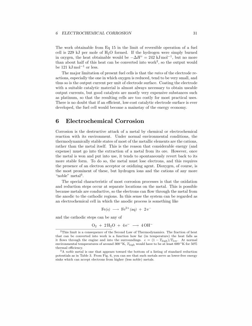
Figure 14: Electrochemical corrosion of a nail showing anodic and cathodicregions
H+ + e− −→ 12 H2(g)
M2+ + 2 e− −→ M(s)
where M is an more noble metal. A thin film of moisture on the surface of themetal can serve as the medium for the electrolyte.
Which parts of the metal serve as anodes and cathodes can depend on manyfactors, as can be seen from the irregular corrosion patterns that are commonlyobserved. Atoms in regions that have undergone stress, as might be producedby forming or machining, often tend to have higher free energies, and thus tendto become anodic, as shown on the nail in Fig. 14.
For part of a metal to act as the site for oxidation and dissolution, it must bein contact with the electrolyte, which may be no more than a film of adsorbedmoisture. However, practically all metallic surfaces that have been exposed tothe atmosphere are coated with a thin film of the metal oxide, which tends toshield the metal from the electrolyte and thus prevent corrosion4. If one part ofa metallic object is protected from the atmosphere so that there is insufficientO2 to build or maintain the oxide film, this “protected” region will often bethe site at which corrosion is most active. The fact that such sites are usuallyhidden from view accounts for much of the difficulty in detecting and controllingcorrosion.
In contrast to anodic sites, which tend to be localized to specific regionsof the surface, the cathodic part of the process can occur almost anywhere.
4Metals such as aluminum and stainless steels form extremely tough and adherent oxidefilms that afford extraordinary corrosion resistance.
6 ELECTROCHEMICAL CORROSION 33
AAAAAAAAAAAAAAAAAAAAAAAAAAAAAAAAAAAAAAAAAA
AAAAAAAAAAAAAAAAAAAAAAAAAA AAAA
AA
AA
AAAAAAAAAAAA
Fe2+
O2
anodic region near bottom of corrosion pit
liquid film
oxide layer protects surface but allows electrons to flow to oxygen
AAAAAAAAAAAAAAA
AAAAAAAAAAAAAAA
air
water
membrane of Fe2O3 attached to meniscus AAA
AAAAAeÑ
(a) (b)
airoxide film
O2
AAAAAAAAAAFe2+
AAAAAAAAAeÑ
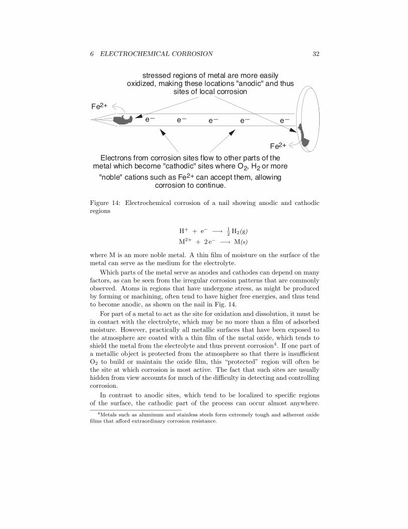
Figure 15: Corrosion in oxygen-deprived regions at pitting and immersion loca-tions
Because metallic oxides are usually semiconductors, most oxide coatings do notinhibit the flow of electrons to the surface, so almost any region that is exposedto O2 or to some other electron acceptor can act as a cathode.
The tendency of oxygen-deprived locations to become anodic is the cause ofmany commonly-observed patterns of corrosion. Thus pitting corrosion (Fig. 15a)begins when corrosion hollows out a narrow hole, or pit, in the metal. The bot-toms of these pits tend to be deprived of oxygen, thus promoting further growthof the pit into the metal. Fig. 15b shows how corrosion of a metal that is par-tially immersed in water is often concentrated at the water line.Rusted-out cars and bathroom stains. Anyone who has owned an older car hasseen corrosion occur at joints between body parts and under paint films. You will alsohave noticed that once corrosion starts, it tends to feed on itself. One reason for thisis that one of the products of the O2 reduction reaction is hydroxide ion. The highpH produced in these cathodic regions tends to destroy the protective oxide film, andmay even soften or weaken paint films, so that these sites can become anodic. Thegreater supply of electrons promotes more intense cathodic action, which spawns evenmore anodic sites, and so on.
A very common cause of corrosion is having two dissimilar metals in contact, asmight occur near a fastener or at a weld joint. Moisture collects at the junction point,acting as an electrolyte and forming a cell in which the two metals serve as electrodes.Moisture and conductive salts on the outside surfaces acts as an external conductor,effectively short-circuiting the cell and producing very rapid corrosion; this is why carsrust out so quickly in places where salt is placed on roads to melt ice.
Dissimilar-metal corrosion can occur even if the two metals are not initially in direct
contact. For example, in homes where copper tubing is used for plumbing, there is
always a small amount of dissolved Cu2+ in the water. When this water encounters
steel piping or a chrome-plated bathroom sink drain, the more-noble copper will plate
out on the other metal, producing a new metals-in-contact corrosion cell. In the case
of chrome bathroom sink fittings, this leads to the formation of Cr3+ salts which
precipitate as greenish stains.
7 ELECTROLYTIC CELLS 34
AAAAAAAAAA
AAAAAAAAAA
AAAAAAAA
AAAAAAAAAAAA
iron iron
zinctin
Zn2+ O2
Fe2+
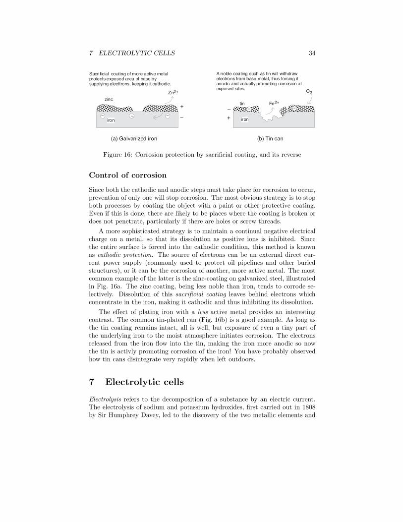
Sacrificial coating of more active metal protects exposed area of base by supplying electtrons, keeping it cathodic.
A noble coating such as tin will withdraw electrons from base metal, thus forcing it anodic and actually promoting corrosion at exposed sites.
(a) Galvanized iron (b) Tin can
AÐ AAÐ+
ÐAAÐ +
Ð
AAÐ
AAÐ
Figure 16: Corrosion protection by sacrificial coating, and its reverse
Control of corrosion
Since both the cathodic and anodic steps must take place for corrosion to occur,prevention of only one will stop corrosion. The most obvious strategy is to stopboth processes by coating the object with a paint or other protective coating.Even if this is done, there are likely to be places where the coating is broken ordoes not penetrate, particularly if there are holes or screw threads.
A more sophisticated strategy is to maintain a continual negative electricalcharge on a metal, so that its dissolution as positive ions is inhibited. Sincethe entire surface is forced into the cathodic condition, this method is knownas cathodic protection. The source of electrons can be an external direct cur-rent power supply (commonly used to protect oil pipelines and other buriedstructures), or it can be the corrosion of another, more active metal. The mostcommon example of the latter is the zinc-coating on galvanized steel, illustratedin Fig. 16a. The zinc coating, being less noble than iron, tends to corrode se-lectively. Dissolution of this sacrificial coating leaves behind electrons whichconcentrate in the iron, making it cathodic and thus inhibiting its dissolution.
The effect of plating iron with a less active metal provides an interestingcontrast. The common tin-plated can (Fig. 16b) is a good example. As long asthe tin coating remains intact, all is well, but exposure of even a tiny part ofthe underlying iron to the moist atmosphere initiates corrosion. The electronsreleased from the iron flow into the tin, making the iron more anodic so nowthe tin is activly promoting corrosion of the iron! You have probably observedhow tin cans disintegrate very rapidly when left outdoors.
7 Electrolytic cells
Electrolysis refers to the decomposition of a substance by an electric current.The electrolysis of sodium and potassium hydroxides, first carried out in 1808by Sir Humphrey Davey, led to the discovery of the two metallic elements and
7 ELECTROLYTIC CELLS 35
showed that these two hydroxides which had previously been considered un-decomposible and thus elements, were in fact compounds:
“By means of a flame which was thrown on a spoon containing potash,this alkali was kept for some minutes at a strong red heat, and in a state ofperfect fluidity.” One pole of a battery of copper-zinc cells was connectedto the spoon, and the other was connected to platinum wire which dippedinto the melt. “By this arrangement some brilliant phenomena were pro-duced. The potash appeared to be a conductor in a high degree, and as longas the communication was preserved, a most intense light was exhibitedat the negative wire, and a column of flame, which seemed to be owing tothe development of combustible matter, arose from the point of contact.”The flame was due to the combustion in the air of metallic potassium. Inanother experiment, Davy observed “small globules having a high metalliclustre, precisely similar in visible characters to quicksilver, some of whichburnt with explosion and bright flame, as soon as they were formed, andothers remained, and were merely tarnished, and finally covered by a whitefilm which formed on their surfaces.”
Electrolysis of molten alkali halides is the usual industrial method of prepar-ing the alkali metals:
cathode reaction: Na+ + e− −→ Na(l)
anode reaction: Cl− −→ 12 Cl2(g) + e−
net reaction: Na+ + Cl− −→ Na(l) + 12 Cl2(g)
Ions in aqueous solutions can undergo similar reactions. Thus if a solution ofnickel chloride undergoes electrolysis at platinum electrodes, the reactions are
cathode: Ni2+ + 2 e− −→ Ni(s) E◦ = −0.24 vanode: 2 Cl− −→ Cl2(g) + 2 e− E◦ = −1.36 v
net reaction: Ni2+ + 2 Cl− −→ Ni(s) + Cl2(g) E◦ = 1.60 v
Both of these processes are carried out in electrochemical cells which areforced to operate in the “reverse”, or non-spontaneous direction, as indicatedby the negative E◦ for the above cell reaction. The free energy is suppliedin the form of electrical work done on the system by the outside world (thesurroundings). This is the only fundamental difference between an electrolyticcell and the galvanic cell in which the free energy supplied by the cell reactionis extracted as work done on the surroundings.
Electrolysis involving water
If we substitute sodium chloride for nickel chloride, dihydrogen is produced atthe cathode instead of sodium:
7 ELECTROLYTIC CELLS 36
cathode: H2O + 2 e− −→ H2(g) + 2 OH− E = +0.41 v ([OH−] = 10−7 M )anode: Cl− −→ 1
2 Cl2(g) + e− E◦ = −1.36 vnet reaction: Na+ + Cl− −→ Na(l) + 1
2 Cl2(g)
The reason that sodium is not a product of this reaction is best understood bylocating the couples Na+/Na and H2O/H2,OH−in Fig. 6 or Table 3. Reductionof Na+ (E◦= 2.7 v) is energetically more difficult than the reduction of water,so in aqueous solution the latter will prevail.
You will recall that water can be oxidized as well as reduced, so if we replacethe chloride ion with an anion such as nitrate or sulfate that is much moredifficult to oxidize, the water is oxidized intead. Electrolysis of a solution ofsulfuric acid or of a salt such as NaNO3 results in the decomposition of waterat both electrodes:
cathode: H2O + 2 e− −→ H2(g) + 2 OH− E = +0.41 v ([OH−] = 10−7 M )anode: 2 H2O −→ O2(g) + 4 H+ + 2 e− E◦ = −0.82 v
net reaction: 2H2O(l) −→ 2 H2(g) + O2(g) E = −1.23 v
Faraday’s laws of electrolysis
One mole of electric charge (96,500 coulombs), when passed through a cell, willdischarge half a mole of a divalent metal ion such as Cu2+. This relation wasfirst formulated by Faraday in 1832 in the form of two laws of electrolysis:
1. The weights of substances formed at an electrode during electrolysis aredirectly proportional to the quantity of electricity that passes through theelectrolyte.
2. The weights of different substances formed by the passage of the samequantity of electricity are proportional to the equivalent weight of eachsubstance.
The equivalent weight of a substance is defined as the molar mass, divided bythe number of electrons required to oxidize or reduce each unit of the substance.Thus one mole of V3+ corresponds to three equivalents of this species, and willrequire three faradays of charge to deposit it as metallic vanadium.
Now that we have a good understanding of electrolytes and electrolysis,the quantitative treatment of electrolytic reactions can be handled by ordinarychemical stoichiometry as in the Problem Example on page 6, so explicit use ofFaraday’s laws is not usually necessary.
7 ELECTROLYTIC CELLS 37
AAAA
AAAA
H2 out
caustic
water
spent brine
brine feed
+ ÐCl2 out
Na+ Na+
ClÑ ® Cl2H2O ® H2 + OHÐ
ion-selective polymer membrane
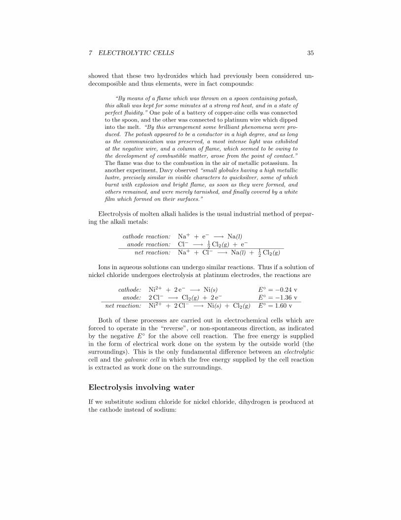
Figure 17: Membrane cell for industrial chloralkali production
Industrial electrolytic processes
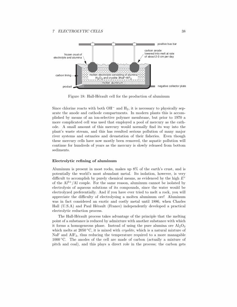
For many industrial-scale operations involving the oxidation or reduction of bothinorganic and organic substances, and especially for the production of the moreactive metals such as sodium, calcium, magnesium, and aluminum, the mostcost-effective reducing agent is electrons supplied by an external power source.The two most economically important of these processes are described below.
The chloralkali industry.
The electrolyis of brine is carried out on a huge scale for the industrial produc-tion of chlorine and caustic soda (sodium hydroxide). Because the reductionpotential of Na+ is much higher than that of water, the latter substance under-goes decomposition at the cathode, yielding hydrogen gas and OH−.
anode: 2 Cl− −→ Cl2(g) + 2 e− −1.36 v i4 OH− −→ O2(g) + 2 H2O + 4 e− −.40 v ii
cathode: Na− + e− −→ Na −2.7 v iii2 H+ + 2 e− −→ H2(g) 0 v iv
A comparison of the E◦s would lead us to predict that reactions (ii) and (iv)would predominate and that (iii) would be unimportant. It is true that sodiumion is not reduced, but as was mentioned in the section on fuel cells, electrodereactions involving O2 are notoriously slow, so even though it is less favoredthermodynamically, reaction (i) predominates over (ii). The net reaction forthe chlorination of brine is thus
2 NaCl(aq) + 2 H2O −→ 2 NaOH + Cl2(g) + H2(g)
7 ELECTROLYTIC CELLS 38
AAAAAAAAAAAAAAAAAAAAAAAAAAAAAAAAAAAAAAAAAAAAAAAAAAAA
AAAAAAAAAAAApositive bus bar
negative collector plate
carbon lining
carbon anodelowered into melt at rate of about 2-3 cm per day
frozen crust of electrolyte and alumina
AAAAmolten aluminumAAAAAAAAAAAAAAAAmolten electrolyte consisting of alumina
Al2O3 and cryolite 3NaF¥AlF3
product
Figure 18: Hall-Herault cell for the production of aluminum
Since chlorine reacts with both OH− and H2, it is necessary to physically sep-arate the anode and cathode compartments. In modern plants this is accom-plished by means of an ion-selective polymer membrane, but prior to 1970 amore complicated cell was used that employed a pool of mercury as the cath-ode. A small amount of this mercury would normally find its way into theplant’s waste stream, and this has resulted serious pollution of many majorriver systems and estuaries and devastation of their fisheries. Even thoughthese mercury cells have now mostly been removed, the aquatic pollution willcontinue for hundreds of years as the mercury is slowly released from bottomsediments.
Electrolytic refining of aluminum
Aluminum is present in most rocks, makes up 8% of the earth’s crust, and ispotentially the world’s most abundant metal. Its isolation, however, is verydifficult to accomplish by purely chemical means, as evidenced by the high E◦
of the Al3+/Al couple. For the same reason, aluminum cannot be isolated byelectrolysis of aqueous solutions of its compounds, since the water would beelectrolyzed preferentially. And if you have ever tried to melt a rock, you willappreciate the difficulty of electrolysing a molten aluminum ore! Aluminumwas in fact considered an exotic and costly metal until 1886, when CharlesHall (U.S.A) and Paul Herault (France) independently developed a practicalelectrolytic reduction process.
The Hall-Herault process takes advantage of the principle that the meltingpoint of a substance is reduced by admixture with another substance with whichit forms a homogeneous phase. Instead of using the pure alumina ore Al2O3
which melts at 2050 ◦C, it is mixed with cryolite, which is a natural mixture ofNaF and AlF3, thus reducing the temperature required to a more managable1000 ◦C. The anodes of the cell are made of carbon (actually a mixture ofpitch and coal), and this plays a direct role in the process; the carbon gets
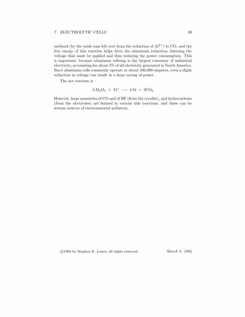
7 ELECTROLYTIC CELLS 39
oxidized (by the oxide ions left over from the reduction of Al3+) to CO, and thefree energy of this reaction helps drive the aluminum reduction, lowering thevoltage that must be applied and thus reducing the power consumption. Thisis important, because aluminum refining is the largest consumer of industrialelectricity, accounting for about 5% of all electricity generated in North America.Since aluminum cells commonly operate at about 100,000 amperes, even a slightreduction in voltage can result in a large saving of power.
The net reaction is
2 Al2O3 + 3 C −→ 4 Al + 3CO2
However, large quantities of CO and of HF (from the cryolite), and hydrocarbons(from the electrodes) are formed in various side reactions, and these can beserious sources of environmental pollution.
c©1994 by Stephen K. Lower; all rights reserved. March 8, 1994


![Electrochemistry Laboratory - SCCER · PDF fileElectrochemistry Laboratory ... Yohan Paratcha, Julien Durst, Juan Herranz, ... Soc., 1991, 138, 3382 [3] Hori et al., Electrochim](https://img.pdfslide.us/doc/110x75/5ab89a327f8b9ac10d8d2b61/electrochemistry-laboratory-sccer-laboratory-yohan-paratcha-julien-durst.jpg)