Embed Size (px)
Citation preview
2012-06-05 AMS Battery & FC Lectures - Fuel Cell (Michele P. for Hubert G.).ppt p. 64
Electrochemistry Basics
- electrochemical cells & ion transport
- electrochemical potential
- half-cell reactions
Lithium Ion Batteries (LiBs)
- battery materials
- application of batteries
- “post-LiBs”
Fuel Cell Basics & Applications
- fuel cell types and materials
- basic electrocatalysis
- H2 reduction & O2 reduction kinetics
- transport resistances
2012-06-05 AMS Battery & FC Lectures - Fuel Cell (Michele P. for Hubert G.).ppt p. 65
Principle of Fuel Cells
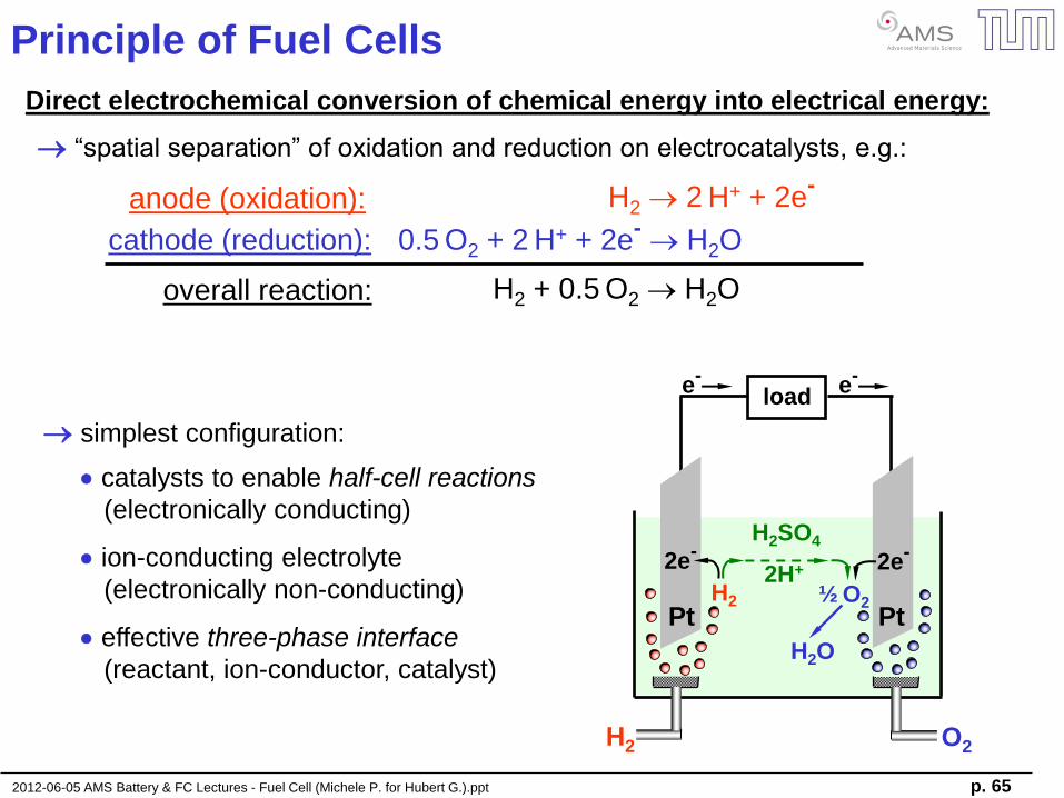
Direct electrochemical conversion of chemical energy into electrical energy:
H2 2 H+ + 2e-
“spatial separation” of oxidation and reduction on electrocatalysts, e.g.:
0.5 O2 + 2 H+ + 2e
- H2O
anode (oxidation):
cathode (reduction):
overall reaction: H2 + 0.5 O2 H2O
simplest configuration:
Pt
H2 O2
Pt
2H+ 2e-
H2 ½ O2
2e-
H2SO4
H2O
load e
- e
-
catalysts to enable half-cell reactions
(electronically conducting)
ion-conducting electrolyte
(electronically non-conducting)
effective three-phase interface
(reactant, ion-conductor, catalyst)
2012-06-05 AMS Battery & FC Lectures - Fuel Cell (Michele P. for Hubert G.).ppt p. 66
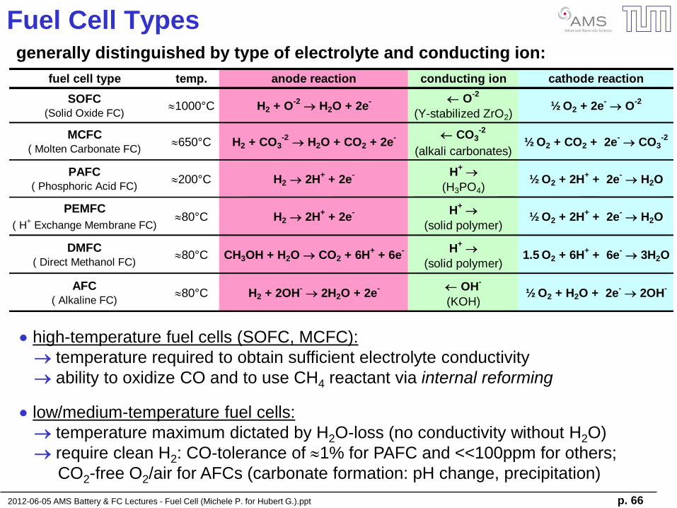
Fuel Cell Types generally distinguished by type of electrolyte and conducting ion:
high-temperature fuel cells (SOFC, MCFC):
temperature required to obtain sufficient electrolyte conductivity
ability to oxidize CO and to use CH4 reactant via internal reforming
low/medium-temperature fuel cells:
temperature maximum dictated by H2O-loss (no conductivity without H2O)
require clean H2: CO-tolerance of 1% for PAFC and <<100ppm for others;
CO2-free O2/air for AFCs (carbonate formation: pH change, precipitation)
fuel cell type temp. anode reaction conducting ion cathode reaction
SOFC(Solid Oxide FC)
1000°C H2 + O-2
H2O + 2e- O
-2
(Y-stabilized ZrO2)½ O2 + 2e
- O
-2
MCFC( Molten Carbonate FC)
650°C H2 + CO3-2
H2O + CO2 + 2e- CO3
-2
(alkali carbonates)½ O2 + CO2 + 2e
- CO3
-2
PAFC( Phosphoric Acid FC)
200°C H2 2H+ + 2e
- H+
(H3PO4)½ O2 + 2H
+ + 2e
- H2O
PEMFC
( H+ Exchange Membrane FC)
80°C H2 2H+ + 2e
- H+
(solid polymer)½ O2 + 2H
+ + 2e
- H2O
DMFC( Direct Methanol FC)
80°C CH3OH + H2O CO2 + 6H+ + 6e
- H+
(solid polymer)1.5 O2 + 6H
+ + 6e
- 3H2O
AFC( Alkaline FC)
80°C H2 + 2OH- 2H2O + 2e
- OH-
(KOH)½ O2 + H2O + 2e
- 2OH
-
2012-06-05 AMS Battery & FC Lectures - Fuel Cell (Michele P. for Hubert G.).ppt p. 67
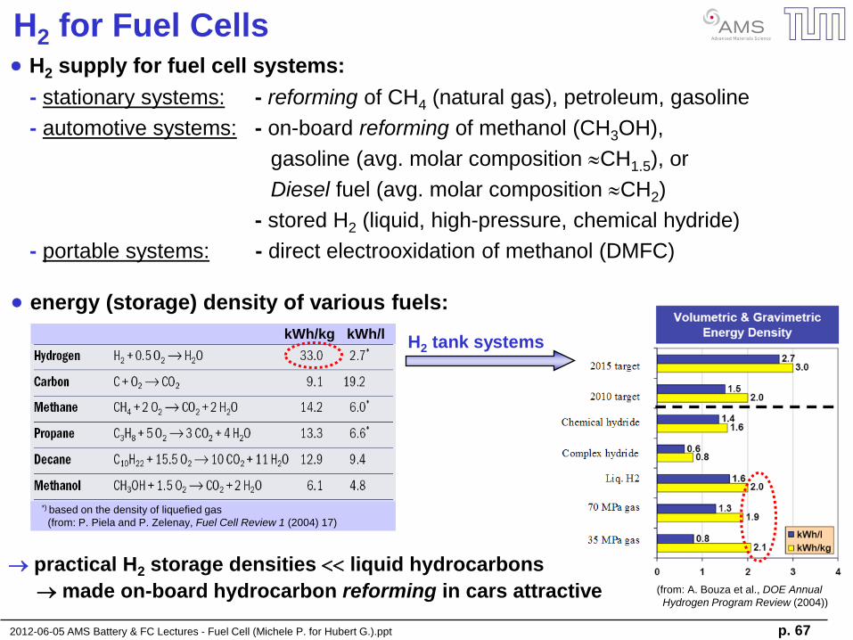
H2 for Fuel Cells H2 supply for fuel cell systems:
- stationary systems: - reforming of CH4 (natural gas), petroleum, gasoline
- automotive systems: - on-board reforming of methanol (CH3OH),
gasoline (avg. molar composition CH1.5), or
Diesel fuel (avg. molar composition CH2)
- stored H2 (liquid, high-pressure, chemical hydride)
- portable systems: - direct electrooxidation of methanol (DMFC)
energy (storage) density of various fuels:
kWh/kg kWh/l
*) based on the density of liquefied gas
(from: P. Piela and P. Zelenay, Fuel Cell Review 1 (2004) 17)
(from: A. Bouza et al., DOE Annual
Hydrogen Program Review (2004))
practical H2 storage densities liquid hydrocarbons
made on-board hydrocarbon reforming in cars attractive
H2 tank systems
2012-06-05 AMS Battery & FC Lectures - Fuel Cell (Michele P. for Hubert G.).ppt p. 68
catalyst cost & supply (100kW car):
currently: 0.5 gPt/kW 50gPt/car at $50/gPt-as-catalyst $25/kW ($50/kWFC-system
target)
long-term: <0.1gPt/kW <10gPt/car with current automotive Pt use: >15 million cars/year
catalyst durability:
1500 hours*) vs. 6000 hour target carbon-support corrosion & Pt-dissolution
advanced catalysts & controls
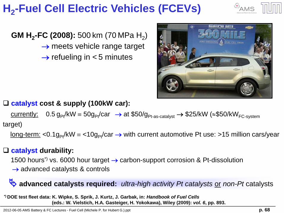
H2-Fuel Cell Electric Vehicles (FCEVs)
GM H2-FC (2008): 500 km (70 MPa H2)
meets vehicle range target
refueling in < 5 minutes
*) DOE test fleet data: K. Wipke, S. Sprik, J. Kurtz, J. Garbak, in: Handbook of Fuel Cells
(eds.: W. Vielstich, H.A. Gasteiger, H. Yokokawa), Wiley (2009): vol. 6, pp. 893.
advanced catalysts required: ultra-high activity Pt catalysts or non-Pt catalysts
2012-06-05 AMS Battery & FC Lectures - Fuel Cell (Michele P. for Hubert G.).ppt p. 69
Thermodynamic Fuel Cell Efficiency
fuel energy content released by combustion:
DHR = DHf
H2O – [DHfH2 + 0.5DHf
O2 ]
(enthalpies of formation from thermodynamic tables)
Wheat produced depends on the state of water:
DHRH2O(liquid) = -285.8 kJ/mol Higher Heating Value (HHV)
DHR(101kPa vapor) = -241.8 kJ/mol Lower Heating Value (LHV)
Wheat = DHR
for H2 + 0.5 O2 H2O :
at 25°C, pH2 =pO2 = 101.3 kPaabs:
DHRH2O(liquid) = -285.8 kJ/mol – [0 kJ/mol + 0 kJ/mol) ] = -285.8 kJ/mol
DHRH2O(101.3kPa vapor) = -241.8 kJ/mol – [0 kJ/mol + 0 kJ/mol) ] = -241.8 kJ/mol
thermodynamic fuel cell efficiency (usually based on HHV):
th = DGRH2O(liquid/vapor)/DHR
H2O(liquid) = -DGRH2O(liquid/vapor)/285.8 kJ/mol
th = 237.1 kJ/mol / 285.8 kJ/mol = 83.05%
for a H2/O2 fuel cell at 25°C and pH2 = pO2 = 101 kPa producing H2O(liquid) :
2012-06-05 AMS Battery & FC Lectures - Fuel Cell (Michele P. for Hubert G.).ppt p. 70
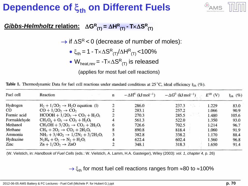
Dependence of th on Different Fuels
Gibbs-Helmholtz relation:
if DSR < 0 (decrease of number of moles):
th = 1 - TDSR(T)/DHR
(T) <100%
Wheat,rev = -TDSR(T) is released
(applies for most fuel cell reactions)
DGR(T) = DHR
(T) - TDSR(T)
th for most fuel cell reactions ranges from 80 to 100%
(W. Vielstich, in: Handbook of Fuel Cells (eds.: W. Vielstich, A. Lamm, H.A. Gasteiger), Wiley (2003): vol. 1, chapter 4, p. 26)
2012-06-05 AMS Battery & FC Lectures - Fuel Cell (Michele P. for Hubert G.).ppt p. 71
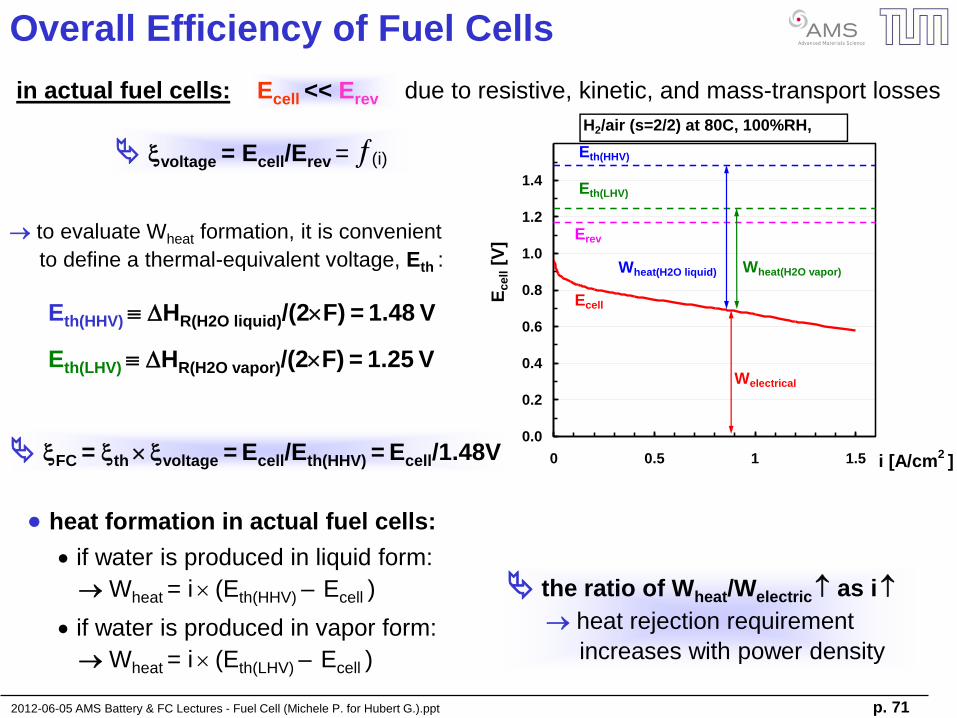
Overall Efficiency of Fuel Cells
in actual fuel cells: Ecell << Erev due to resistive, kinetic, and mass-transport losses
Eth(HHV) DHR(H2O liquid)/(2F) = 1.48 V
to evaluate Wheat formation, it is convenient
to define a thermal-equivalent voltage, Eth :
voltage = Ecell/Erev = (i)
Eth(LHV) DHR(H2O vapor)/(2F) = 1.25 V
0.0
0.2
0.4
0.6
0.8
1.0
1.2
1.4
0 0.5 1 1.5 i [A/cm2 ]
Ecell [
V]
Eth(HHV)
H2/air (s=2/2) at 80C, 100%RH,
150kPaabs
Eth(LHV)
Ecell
Erev
Wheat(H2O liquid) Wheat(H2O vapor)
Welectrical
FC = th voltage = Ecell/Eth(HHV) = Ecell/1.48V
heat formation in actual fuel cells:
if water is produced in liquid form:
Wheat = i (Eth(HHV) – Ecell )
if water is produced in vapor form:
Wheat = i (Eth(LHV) – Ecell )
the ratio of Wheat/Welectric as i
heat rejection requirement
increases with power density
2012-06-05 AMS Battery & FC Lectures - Fuel Cell (Michele P. for Hubert G.).ppt p. 72
Proton Exchange Membrane Fuel Cell Materials
2012-06-05 AMS Battery & FC Lectures - Fuel Cell (Michele P. for Hubert G.).ppt p. 73
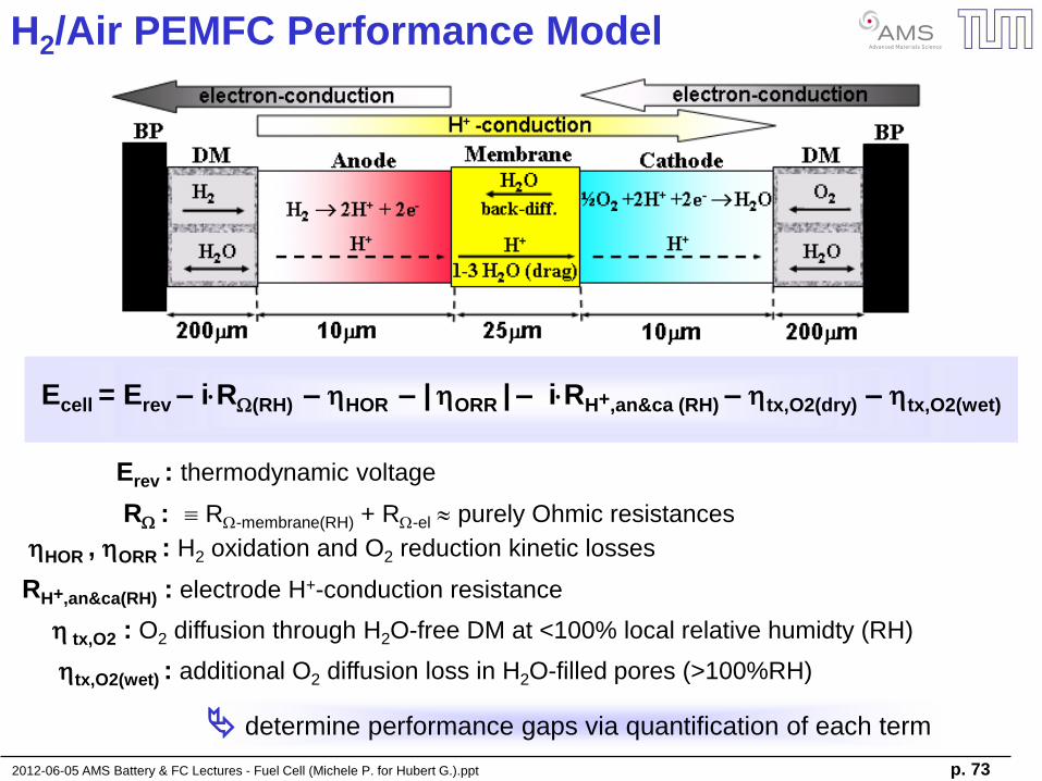
H2/Air PEMFC Performance Model
Ecell = Erev – iRW(RH) – hHOR – | hORR | – iRH+,an&ca (RH) – htx,O2(dry) – htx,O2(wet)
Erev : thermodynamic voltage
RW : RW-membrane(RH) + RW-el purely Ohmic resistances
hHOR , hORR : H2 oxidation and O2 reduction kinetic losses
RH+,an&ca(RH) : electrode H+-conduction resistance
h tx,O2 : O2 diffusion through H2O-free DM at <100% local relative humidty (RH)
htx,O2(wet) : additional O2 diffusion loss in H2O-filled pores (>100%RH)
determine performance gaps via quantification of each term
2012-06-05 AMS Battery & FC Lectures - Fuel Cell (Michele P. for Hubert G.).ppt p. 74
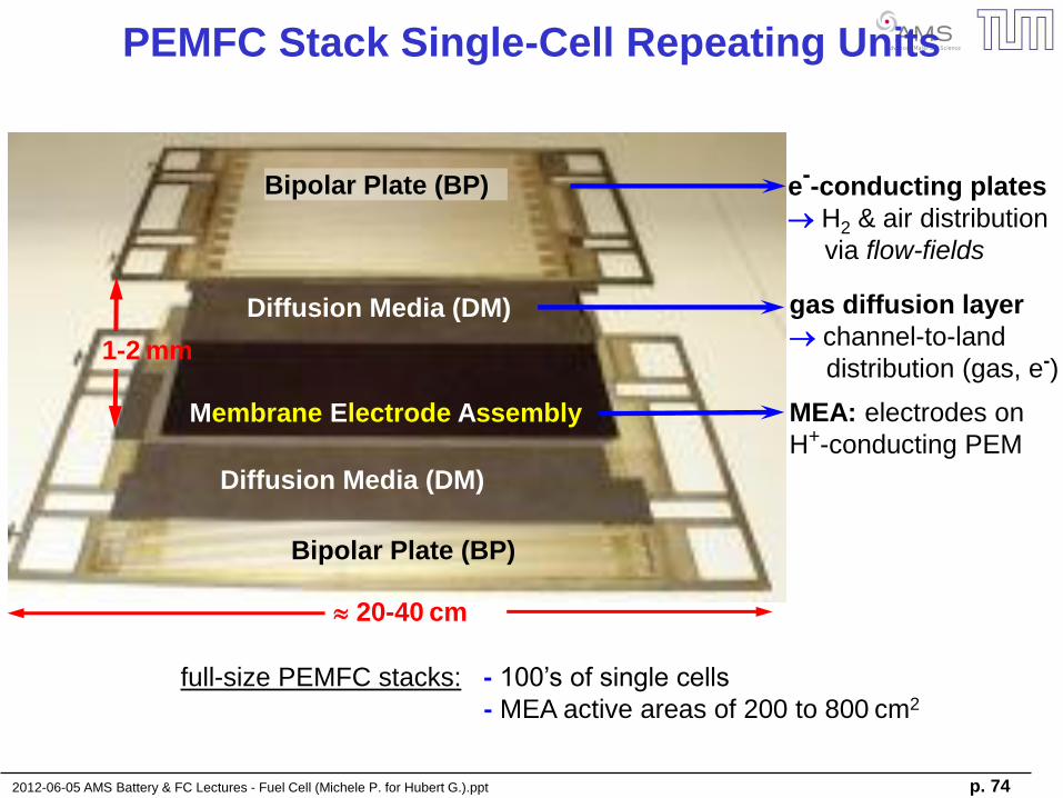
Membrane Electrode Assembly
Diffusion Media (DM)
Diffusion Media (DM)
Bipolar Plate (BP)
Bipolar Plate (BP)
PEMFC Stack Single-Cell Repeating Units
e--conducting plates
H2 & air distribution
via flow-fields
gas diffusion layer
channel-to-land
distribution (gas, e-)
MEA: electrodes on
H+-conducting PEM
full-size PEMFC stacks: - 100’s of single cells
- MEA active areas of 200 to 800 cm2
20-40 cm
1-2 mm
2012-06-05 AMS Battery & FC Lectures - Fuel Cell (Michele P. for Hubert G.).ppt p. 75
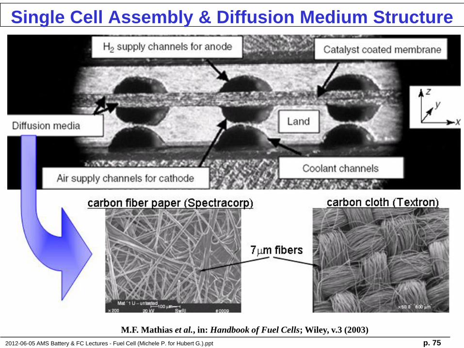
Single Cell Assembly & Diffusion Medium Structure
M.F. Mathias et al., in: Handbook of Fuel Cells; Wiley, v.3 (2003)
2012-06-05 AMS Battery & FC Lectures - Fuel Cell (Michele P. for Hubert G.).ppt p. 76
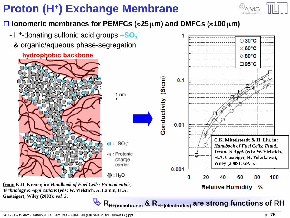
Proton (H+) Exchange Membrane
from: K.D. Kreuer, in: Handbook of Fuel Cells: Fundamentals,
Technology & Applications (eds: W. Vielstich, A. Lamm, H.A.
Gasteiger), Wiley (2003): vol. 3.
ionomeric membranes for PEMFCs (25 mm) and DMFCs (100 mm)
- H+-donating sulfonic acid groups –SO3-
& organic/aqueous phase-segregation
hydrophobic backbone
C.K. Mittelsteadt & H. Liu, in:
Handbook of Fuel Cells: Fund.,
Techn. & Appl. (eds: W. Vielstich,
H.A. Gasteiger, H. Yokokawa),
Wiley (2009): vol. 5.
RH+(membrane) & RH+(electrodes) are strong functions of RH
2012-06-05 AMS Battery & FC Lectures - Fuel Cell (Michele P. for Hubert G.).ppt p. 77
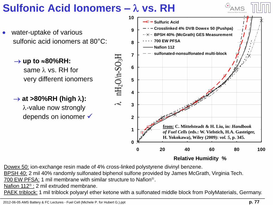
Sulfonic Acid Ionomers – l vs. RH
Dowex 50: ion-exchange resin made of 4% cross-linked polystyrene divinyl benzene.
BPSH 40: 2 mil 40% randomly sulfonated biphenol sulfone provided by James McGrath, Virginia Tech.
700 EW PFSA: 1 mil membrane with similar structure to Nafion.
Nafion 112 : 2 mil extruded membrane.
PAEK triblock: 1 mil triblock polyaryl ether ketone with a sulfonated middle block from PolyMaterials, Germany.
up to 80%RH:
same l vs. RH for
very different ionomers
water-uptake of various
sulfonic acid ionomers at 80°C:
at >80%RH (high l):
l-value now strongly
depends on ionomer
0
1
2
3
4
5
6
7
8
9
10
0 20 40 60 80 100
Relative Humidity %
Sulfuric Acid
Crosslinked 4% DVB Dowex 50 (Pushpa)
BPSH 40% (McGrath) GES Measurement
700 EW PFSA
Nafion 112
sulfonated-nonsulfonated multi-block
l n
H2O
/n-S
O3H
from: C. Mittelsteadt & H. Liu, in: Handbook
of Fuel Cells (eds.: W. Vielstich, H.A. Gasteiger,
H. Yokokawa), Wiley (2009): vol. 5, p. 345.
2012-06-05 AMS Battery & FC Lectures - Fuel Cell (Michele P. for Hubert G.).ppt p. 78
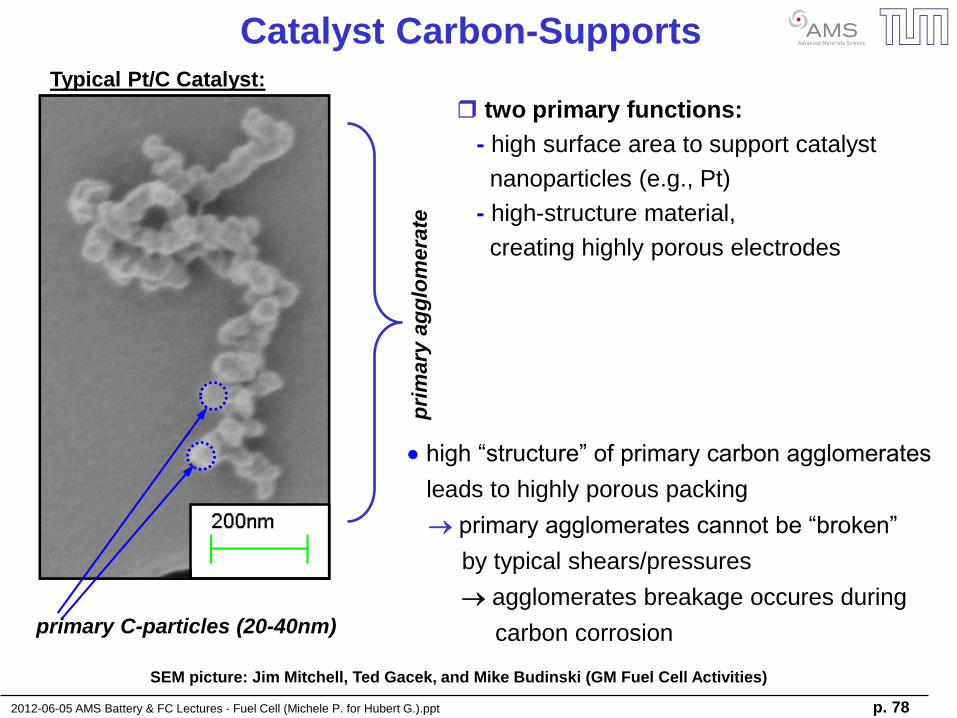
Catalyst Carbon-Supports Typical Pt/C Catalyst:
pri
mary
ag
glo
mera
te
primary C-particles (20-40nm)
high “structure” of primary carbon agglomerates
leads to highly porous packing
primary agglomerates cannot be “broken”
by typical shears/pressures
agglomerates breakage occures during
carbon corrosion
SEM picture: Jim Mitchell, Ted Gacek, and Mike Budinski (GM Fuel Cell Activities)
two primary functions:
- high surface area to support catalyst
nanoparticles (e.g., Pt)
- high-structure material,
creating highly porous electrodes
2012-06-05 AMS Battery & FC Lectures - Fuel Cell (Michele P. for Hubert G.).ppt p. 79
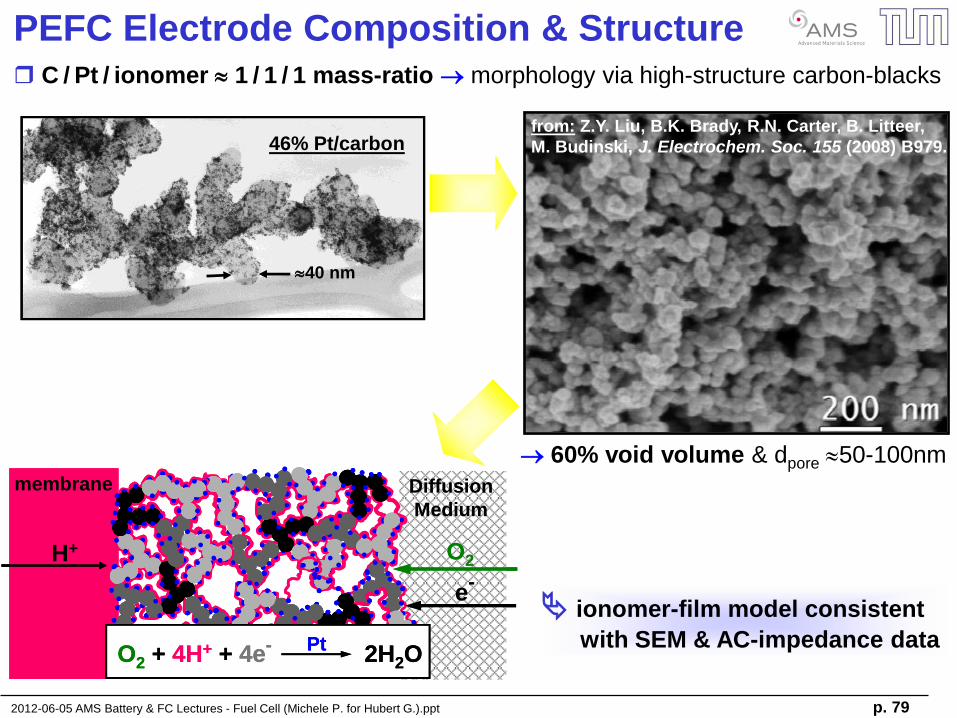
PEFC Electrode Composition & Structure
C / Pt / ionomer 1 / 1 / 1 mass-ratio morphology via high-structure carbon-blacks
40 nm
46% Pt/carbon
40 nm
46% Pt/carbon
60% void volume & dpore 50-100nm
from: Z.Y. Liu, B.K. Brady, R.N. Carter, B. Litteer,
M. Budinski, J. Electrochem. Soc. 155 (2008) B979.
membrane
H+
e-
O2
O2 + 4H+ + 4e- 2H2OPt
Diffusion
Medium
membrane
H+
e-
O2
O2 + 4H+ + 4e- 2H2OPt
O2 + 4H+ + 4e- 2H2OPt
O2 + 4H+ + 4e- 2H2OPt
Diffusion
Medium
ionomer-film model consistent
with SEM & AC-impedance data
2012-06-05 AMS Battery & FC Lectures - Fuel Cell (Michele P. for Hubert G.).ppt p. 80
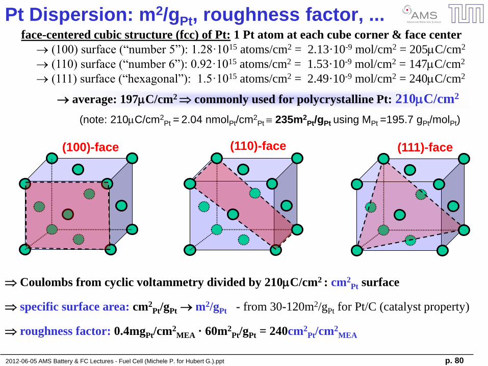
Pt Dispersion: m2/gPt, roughness factor, ... face-centered cubic structure (fcc) of Pt: 1 Pt atom at each cube corner & face center
(100) surface (“number 5”): 1.28·1015 atoms/cm2 = 2.13·10-9 mol/cm2 = 205mC/cm2
(110) surface (“number 6”): 0.92·1015 atoms/cm2 = 1.53·10-9 mol/cm2 = 147mC/cm2
(111) surface (“hexagonal”): 1.5·1015 atoms/cm2 = 2.49·10-9 mol/cm2 = 240mC/cm2
Coulombs from cyclic voltammetry divided by 210mC/cm2 : cm2Pt surface
specific surface area: cm2Pt/gPt m2/gPt - from 30-120m2/gPt for Pt/C (catalyst property)
roughness factor: 0.4mgPt/cm2MEA · 60m2
Pt/gPt = 240cm2Pt/cm2
MEA
(note: 210mC/cm2Pt = 2.04 nmolPt/cm2
Pt 235m2Pt/gPt using MPt =195.7 gPt/molPt)
(100)-face (110)-face (111)-face
average: 197mC/cm2 commonly used for polycrystalline Pt: 210mC/cm2
2012-06-05 AMS Battery & FC Lectures - Fuel Cell (Michele P. for Hubert G.).ppt p. 81
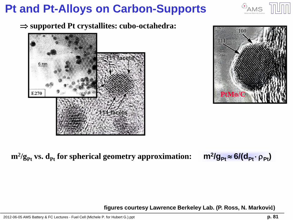
Pt and Pt-Alloys on Carbon-Supports
supported Pt crystallites: cubo-octahedra:
PtMo/C
m2/gPt vs. dPt for spherical geometry approximation: m2/gPt 6/(dPt rPt)
figures courtesy Lawrence Berkeley Lab. (P. Ross, N. Marković)
2012-06-05 AMS Battery & FC Lectures - Fuel Cell (Michele P. for Hubert G.).ppt p. 82
-40
-30
-20
-10
0
10
20
0.0 0.2 0.4 0.6 0.8 1.0 1.2 E/V [RHE]
i [ A
/g P
t ]
thin-film GC in 0.1M HClO4
50cm2 MEA w. 63 sccm N2
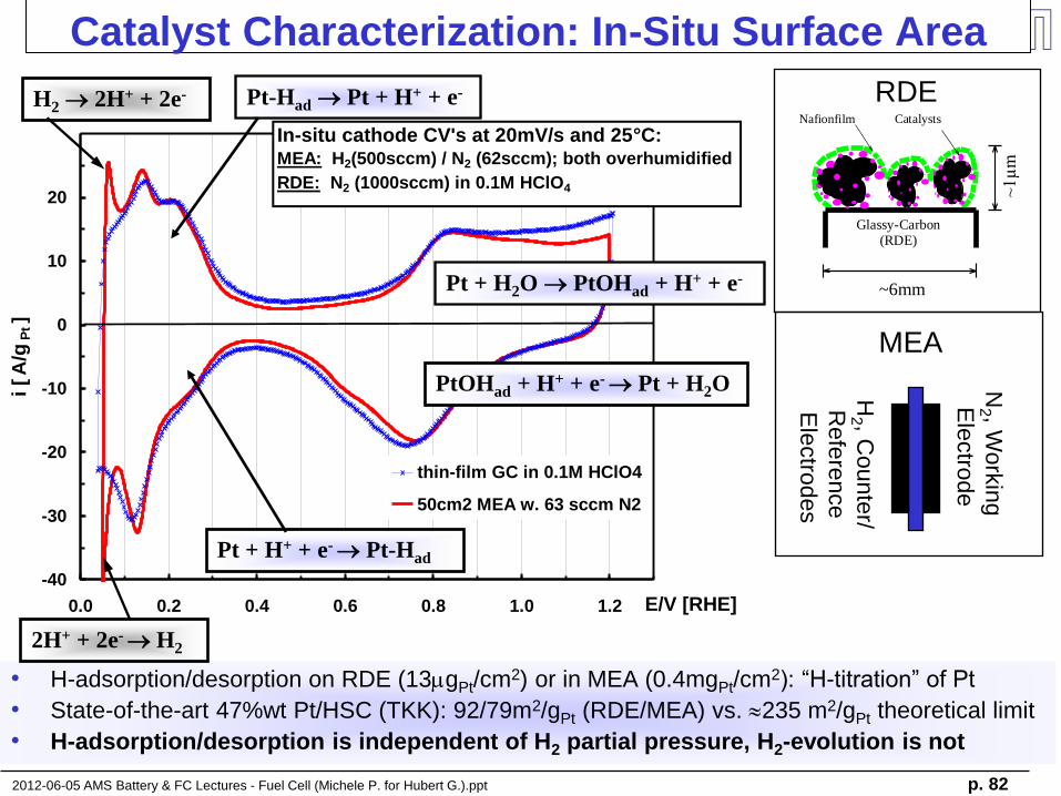
In-situ cathode CV's at 20mV/s and 25°C:MEA: H2(500sccm) / N2 (62sccm); both overhumidified
RDE: N2 (1000sccm) in 0.1M HClO4
Catalyst Characterization: In-Situ Surface Area
• H-adsorption/desorption on RDE (13mgPt/cm2) or in MEA (0.4mgPt/cm2): “H-titration” of Pt
• State-of-the-art 47%wt Pt/HSC (TKK): 92/79m2/gPt (RDE/MEA) vs. 235 m2/gPt theoretical limit
• H-adsorption/desorption is independent of H2 partial pressure, H2-evolution is not
Nafionfilm
Glassy-Carbon(RDE)
Catalysts
~6mm
~1µm
RDE
MEA
N2 , W
ork
ing
Ele
ctro
de
H2 , C
ounte
r/
Refe
rence
Ele
ctro
des
Pt-Had Pt + H+ + e-
Pt + H+ + e- Pt-Had
2H+ + 2e- H2
Pt + H2O PtOHad + H+ + e-
PtOHad + H+ + e- Pt + H2O
H2 2H+ + 2e-
2012-06-05 AMS Battery & FC Lectures - Fuel Cell (Michele P. for Hubert G.).ppt p. 83
Electrochemistry Basics
- electrochemical cells & ion transport
- electrochemical potential
- half-cell reactions
Lithium Ion Batteries (LiBs)
- battery materials
- application of batteries
- “post-LiBs”
Fuel Cell Basics & Applications
- fuel cell types and materials
- basic electrocatalysis
- H2 reduction & O2 reduction kinetics
- transport resistances
2012-06-05 AMS Battery & FC Lectures - Fuel Cell (Michele P. for Hubert G.).ppt p. 84
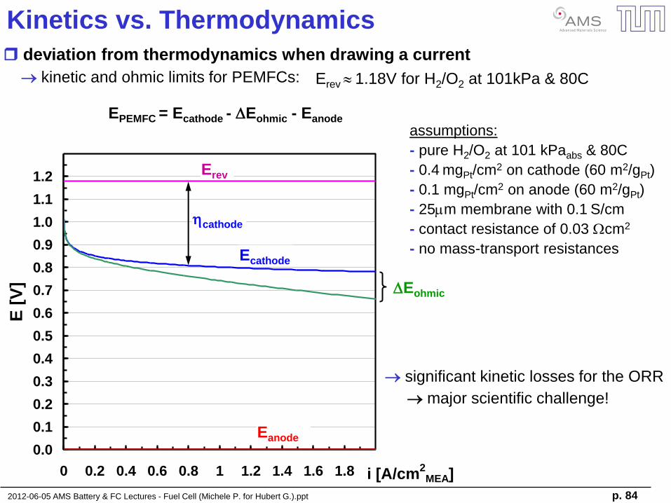
Kinetics vs. Thermodynamics
deviation from thermodynamics when drawing a current
kinetic and ohmic limits for PEMFCs:
0.0
0.1
0.2
0.3
0.4
0.5
0.6
0.7
0.8
0.9
1.0
1.1
1.2
0 0.2 0.4 0.6 0.8 1 1.2 1.4 1.6 1.8 i [A/cm2
MEA]
E [
V]
Erev 1.18V for H2/O2 at 101kPa & 80C
Erev
Ecathode
Eanode
DEohmic
EPEMFC = Ecathode - DEohmic - Eanode
hcathode
assumptions:
- pure H2/O2 at 101 kPaabs & 80C
- 0.4 mgPt/cm2 on cathode (60 m2/gPt)
- 0.1 mgPt/cm2 on anode (60 m2/gPt)
- 25mm membrane with 0.1 S/cm
- contact resistance of 0.03 Wcm2
- no mass-transport resistances
significant kinetic losses for the ORR
major scientific challenge!
2012-06-05 AMS Battery & FC Lectures - Fuel Cell (Michele P. for Hubert G.).ppt p. 85
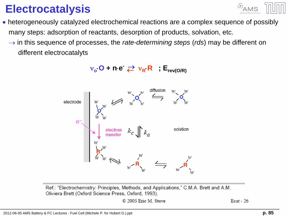
Electrocatalysis heterogeneously catalyzed electrochemical reactions are a complex sequence of possibly
many steps: adsorption of reactants, desorption of products, solvation, etc.
in this sequence of processes, the rate-determining steps (rds) may be different on
different electrocatalyts
noO + ne- nRR ; Erev(O/R)
2012-06-05 AMS Battery & FC Lectures - Fuel Cell (Michele P. for Hubert G.).ppt p. 86
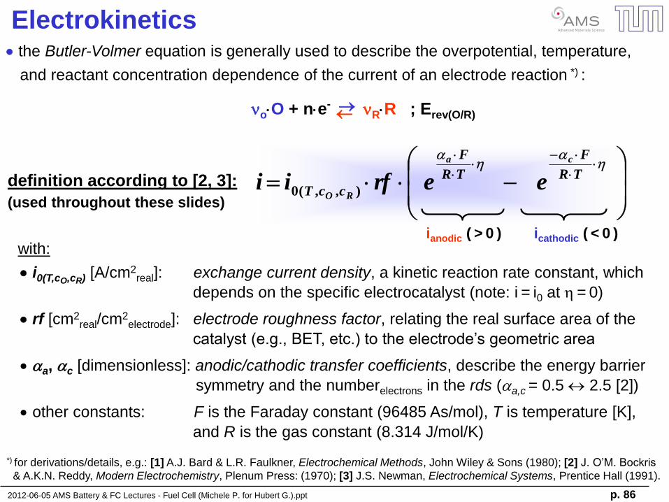
Electrokinetics
h
h
TR
F
TR
F
ccT
ca
ROeerfii ),,(0
the Butler-Volmer equation is generally used to describe the overpotential, temperature,
and reactant concentration dependence of the current of an electrode reaction *) :
*) for derivations/details, e.g.: [1] A.J. Bard & L.R. Faulkner, Electrochemical Methods, John Wiley & Sons (1980); [2] J. O’M. Bockris
& A.K.N. Reddy, Modern Electrochemistry, Plenum Press: (1970); [3] J.S. Newman, Electrochemical Systems, Prentice Hall (1991).
definition according to [2, 3]:
(used throughout these slides)
ianodic ( > 0 ) icathodic ( < 0 )
noO + ne- nRR ; Erev(O/R)
with:
i0(T,cO,cR) [A/cm2real]: exchange current density, a kinetic reaction rate constant, which
depends on the specific electrocatalyst (note: i = i0 at h = 0)
rf [cm2real/cm2
electrode]: electrode roughness factor, relating the real surface area of the
catalyst (e.g., BET, etc.) to the electrode’s geometric area
a, c [dimensionless]: anodic/cathodic transfer coefficients, describe the energy barrier
symmetry and the numberelectrons in the rds (a,c = 0.5 2.5 [2])
other constants: F is the Faraday constant (96485 As/mol), T is temperature [K],
and R is the gas constant (8.314 J/mol/K)
2012-06-05 AMS Battery & FC Lectures - Fuel Cell (Michele P. for Hubert G.).ppt p. 87
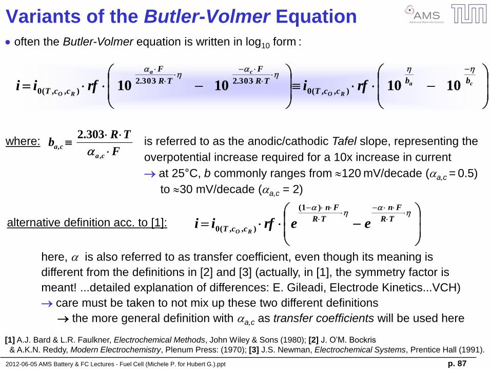
Variants of the Butler-Volmer Equation
ca
RO
ca
RO
bb
ccT
TR
F
TR
F
ccT rfirfii
hhh
h
10101010 ),,(0
303.2303.2
),,(0
F
TRb
ca
a,c
,
303.2
often the Butler-Volmer equation is written in log10 form :
where: is referred to as the anodic/cathodic Tafel slope, representing the
overpotential increase required for a 10x increase in current
at 25°C, b commonly ranges from 120 mV/decade (a,c = 0.5)
to 30 mV/decade (a,c = 2)
alternative definition acc. to [1]:
h
h
TR
Fn
TR
Fn
ccT eerfiiRO
)1(
),,(0
here, is also referred to as transfer coefficient, even though its meaning is
different from the definitions in [2] and [3] (actually, in [1], the symmetry factor is
meant! ...detailed explanation of differences: E. Gileadi, Electrode Kinetics...VCH)
care must be taken to not mix up these two different definitions
the more general definition with a,c as transfer coefficients will be used here
[1] A.J. Bard & L.R. Faulkner, Electrochemical Methods, John Wiley & Sons (1980); [2] J. O’M. Bockris
& A.K.N. Reddy, Modern Electrochemistry, Plenum Press: (1970); [3] J.S. Newman, Electrochemical Systems, Prentice Hall (1991).
2012-06-05 AMS Battery & FC Lectures - Fuel Cell (Michele P. for Hubert G.).ppt p. 88
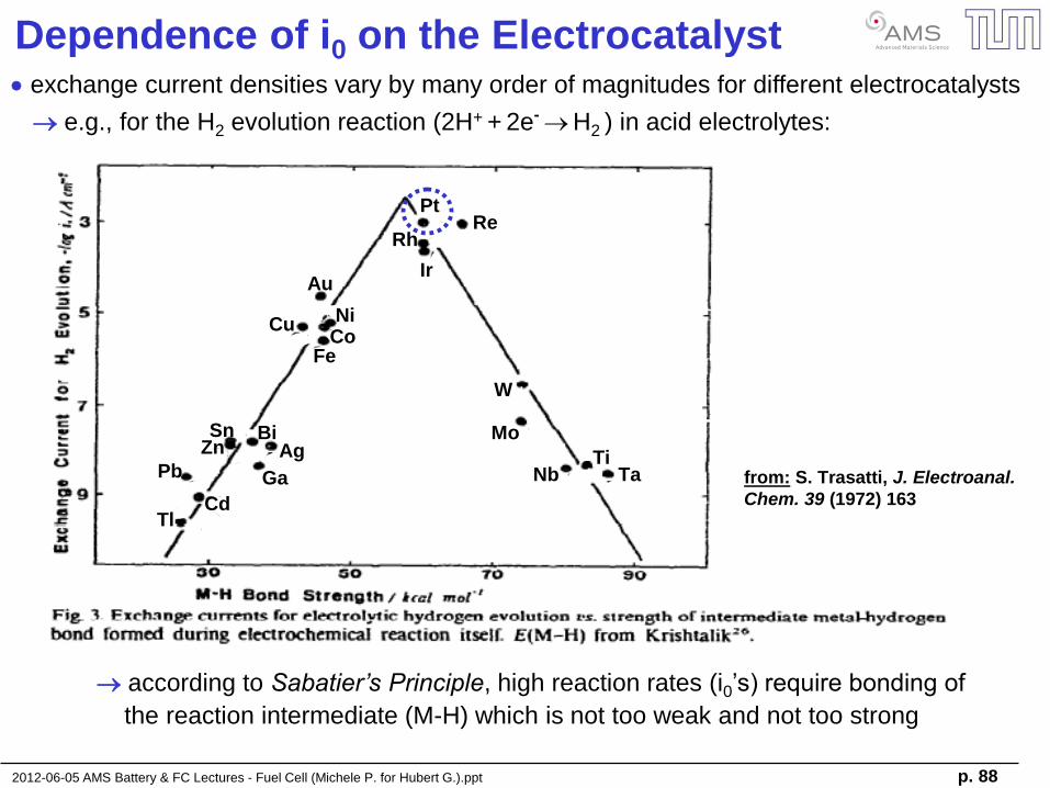
Dependence of i0 on the Electrocatalyst exchange current densities vary by many order of magnitudes for different electrocatalysts
e.g., for the H2 evolution reaction (2H+ + 2e- H2 ) in acid electrolytes:
according to Sabatier’s Principle, high reaction rates (i0’s) require bonding of
the reaction intermediate (M-H) which is not too weak and not too strong
Au
NiCo
Fe
Cu
PtRe
Rh
Ir
W
Mo
NbTi
Ta
Sn BiAgZn
GaPb
CdTl
from: S. Trasatti, J. Electroanal.
Chem. 39 (1972) 163
Au
NiCo
Fe
Cu
PtRe
Rh
Ir
W
Mo
NbTi
Ta
Sn BiAgZn
GaPb
CdTl
Au
NiCo
Fe
Cu
PtRe
Rh
Ir
W
Mo
NbTi
Ta
Sn BiAgZn
GaPb
CdTl
Au
NiCo
Fe
Cu
PtRe
Rh
Ir
W
Mo
NbTi
Ta
Sn BiAgZn
GaPb
CdTl
from: S. Trasatti, J. Electroanal.
Chem. 39 (1972) 163
2012-06-05 AMS Battery & FC Lectures - Fuel Cell (Michele P. for Hubert G.).ppt p. 89
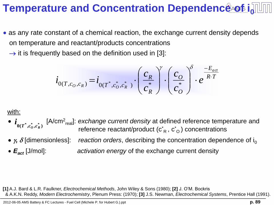
Temperature and Concentration Dependence of i0
),,(0 ***RO ccT
i
as any rate constant of a chemical reaction, the exchange current density depends
on temperature and reactant/products concentrations
it is frequently based on the definition used in [3]:
[1] A.J. Bard & L.R. Faulkner, Electrochemical Methods, John Wiley & Sons (1980); [2] J. O’M. Bockris
& A.K.N. Reddy, Modern Electrochemistry, Plenum Press: (1970); [3] J.S. Newman, Electrochemical Systems, Prentice Hall (1991).
with:
[A/cm2real]: exchange current density at defined reference temperature and
reference reactant/product (c*R , c
*O ) concentrations
g, d [dimensionless]: reaction orders, describing the concentration dependence of i0
Eact [J/mol]: activation energy of the exchange current density
TR
E
O
O
R
R
ccTccT
act
ROROe
c
c
c
cii
dg
**),,(0),,(0 ***
2012-06-05 AMS Battery & FC Lectures - Fuel Cell (Michele P. for Hubert G.).ppt p. 90
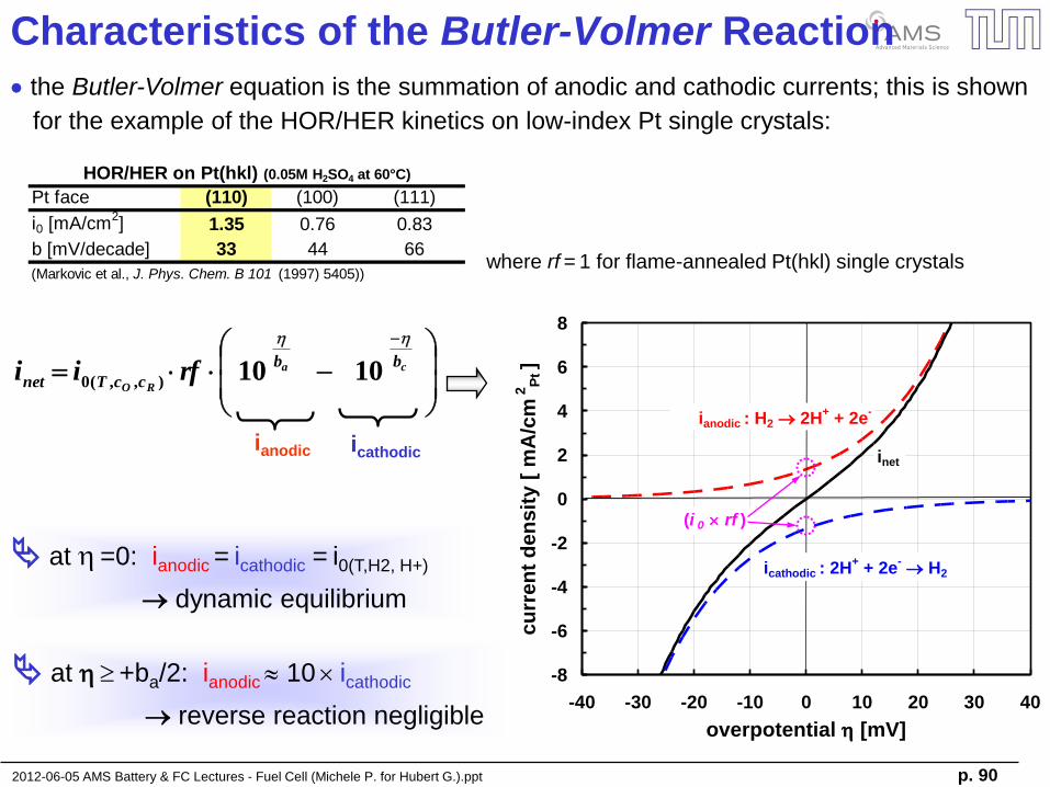
Characteristics of the Butler-Volmer Reaction
ca
RO
bb
ccTnet rfii
hh
1010),,(0
the Butler-Volmer equation is the summation of anodic and cathodic currents; this is shown
for the example of the HOR/HER kinetics on low-index Pt single crystals:
Pt face (110) (100) (111)
i0 [mA/cm2] 1.35 0.76 0.83
b [mV/decade] 33 44 66
(Markovic et al., J. Phys. Chem. B 101 (1997) 5405))
HOR/HER on Pt(hkl) (0.05M H2SO4 at 60°C)
where rf = 1 for flame-annealed Pt(hkl) single crystals
ianodic icathodic
at h =0: ianodic = icathodic = i0(T,H2, H+)
dynamic equilibrium
at h +ba/2: ianodic 10 icathodic
reverse reaction negligible
-8
-6
-4
-2
0
2
4
6
8
-40 -30 -20 -10 0 10 20 30 40
overpotential h [mV]
cu
rre
nt
de
ns
ity
[ m
A/c
m 2
Pt ]
icathodic : 2H+ + 2e
- H2
ianodic : H2 2H+ + 2e
-
inet
(i 0 rf )
2012-06-05 AMS Battery & FC Lectures - Fuel Cell (Michele P. for Hubert G.).ppt p. 91
-25
-20
-15
-10
-5
0
5
10
15
20
25
-100 -80 -60 -40 -20 0 20 40 60 80 100
overpotential h [mV]
cu
rre
nt
de
ns
ity
[ m
A/c
m 2
Pt ]
H2 2H+ + 2e
-
2H+ + 2e
- H2
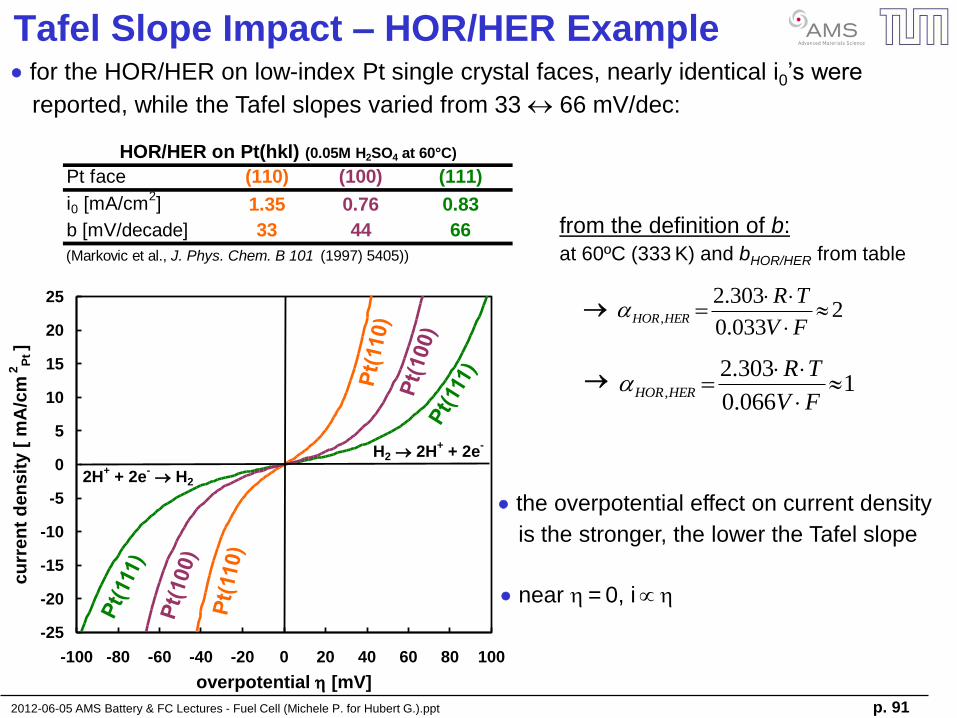
Tafel Slope Impact – HOR/HER Example
1066.0
303.2,
FV
TRHERHOR
for the HOR/HER on low-index Pt single crystal faces, nearly identical i0’s were
reported, while the Tafel slopes varied from 33 66 mV/dec:
Pt face (110) (100) (111)
i0 [mA/cm2] 1.35 0.76 0.83
b [mV/decade] 33 44 66
(Markovic et al., J. Phys. Chem. B 101 (1997) 5405))
HOR/HER on Pt(hkl) (0.05M H2SO4 at 60°C)
2033.0
303.2,
FV
TRHERHOR
from the definition of b:
at 60ºC (333 K) and bHOR/HER from table
the overpotential effect on current density
is the stronger, the lower the Tafel slope
near h = 0, i h
2012-06-05 AMS Battery & FC Lectures - Fuel Cell (Michele P. for Hubert G.).ppt p. 92
Butler-Volmer: Linear Approximation
h
h h
h
TR
Fe
TR
Fe cTR
F
aTR
F ca
1 and1
F
TR
F
TR
ba
h
h and1and1
h
h
TR
F
TR
F ca
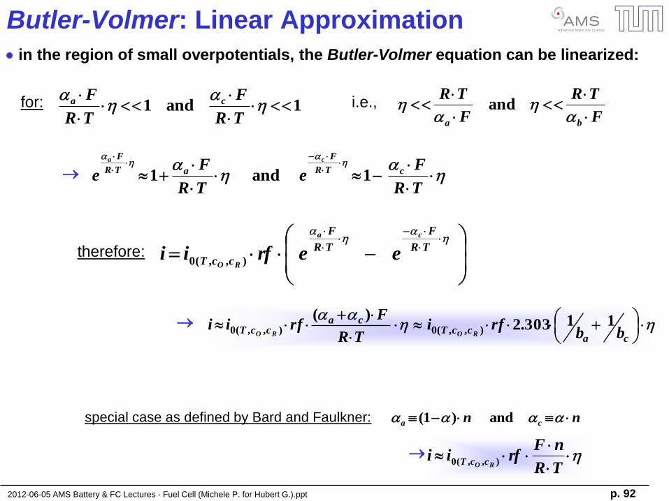
in the region of small overpotentials, the Butler-Volmer equation can be linearized:
for: i.e.,
h
h
TR
F
TR
F
ccT
ca
ROeerfii ),,(0
therefore:
hh
caccT
caccT bb
rfiTR
Frfii
RORO
11303.2)(
),,(0),,(0
special case as defined by Bard and Faulkner: nn ca and)1(
h
TR
nFrfii
RO ccT ),,(0
2012-06-05 AMS Battery & FC Lectures - Fuel Cell (Michele P. for Hubert G.).ppt p. 93
Butler-Volmer: Linear Approximation
txech
caccT
RF
TR
i
F
TRrfi
RO
arg
),,(0
1
)(h
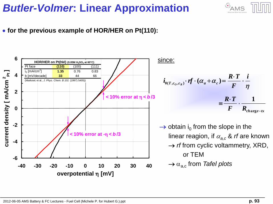
for the previous example of HOR/HER on Pt(110):
obtain i0 from the slope in the
linear reagion, if a,c & rf are known
rf from cyclic voltammetry, XRD,
or TEM
a,c from Tafel plots
since:
-6
-4
-2
0
2
4
6
-40 -30 -20 -10 0 10 20 30 40
overpotential h [mV]
cu
rren
t d
en
sit
y [
mA
/cm
2P
t ]
< 10% error at -h < b /3
< 10% error at h < b /3
Pt face (110) (100) (111)
i0 [mA/cm2] 1.35 0.76 0.83
b [mV/decade] 33 44 66
(Markovic et al., J. Phys. Chem. B 101 (1997) 5405))
HOR/HER on Pt(hkl) (0.05M H2SO4 at 60°C)

2012-06-05 AMS Battery & FC Lectures - Fuel Cell (Michele P. for Hubert G.).ppt p. 94
Butler-Volmer: Tafel Approximation
ca bandb hh1and1 ca bb
hh
a
RO
ca
RO
b
ccT
bb
ccTanodic rfirfii
hhh
101010 ),,(0),,(0
at large overpotentials, one of the Butler-Volmer equation terms becomes negligible:
for: i.e.,
for anodic processes (h ba,c):
or, more commonly:
F
TRb
ca
a,c
,
303.2
(where )
10 0.1
ha
ccTanodicb
rfiiRO
1log)log( ),,(0
for cathodic processes (h ba,c): hc
ccTcathodicb
rfiiRO
1log)log( ),,(0
the log(i) vs. h relationship at high h is commonly referred to as Tafel equation
2012-06-05 AMS Battery & FC Lectures - Fuel Cell (Michele P. for Hubert G.).ppt p. 95
0.1
1
10
100
-100 -80 -60 -40 -20 0 20 40 60 80 100
overpotential h [mV]
log
( |i
| ) [
mA
/cm
2P
t ]
H2 2H+ + 2e
-2H
+ + 2e
- H2
(i 0 rf )
(b a )-1(b c )
-
Butler-Volmer: Tafel Approximation
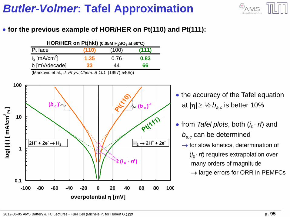
Pt face (110) (100) (111)
i0 [mA/cm2] 1.35 0.76 0.83
b [mV/decade] 33 44 66
(Markovic et al., J. Phys. Chem. B 101 (1997) 5405))
HOR/HER on Pt(hkl) (0.05M H2SO4 at 60°C)
for the previous example of HOR/HER on Pt(110) and Pt(111):
the accuracy of the Tafel equation
at |h| ½ba,c is better 10%
from Tafel plots, both (i0 rf) and
ba,c can be determined
for slow kinetics, determination of
(i0 rf) requires extrapolation over
many orders of magnitude
large errors for ORR in PEMFCs
2012-06-05 AMS Battery & FC Lectures - Fuel Cell (Michele P. for Hubert G.).ppt p. 96
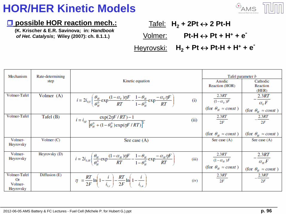
HOR/HER Kinetic Models
possible HOR reaction mech.: Tafel: H2 + 2Pt 2 Pt-H
Pt-H Pt + H+ + e- Volmer: (K. Krischer & E.R. Savinova; in: Handbook
of Het. Catalysis; Wiley (2007): ch. 8.1.1.)
H2 + Pt Pt-H + H+ + e- Heyrovski:
2012-06-05 AMS Battery & FC Lectures - Fuel Cell (Michele P. for Hubert G.).ppt p. 97
Electrochemistry Basics
- electrochemical cells & ion transport
- electrochemical potential
- half-cell reactions
Lithium Ion Batteries (LiBs)
- battery materials
- application of batteries
- “post-LiBs”
Fuel Cell Basics & Applications
- fuel cell types and materials
- basic electrocatalysis
- H2 reduction & O2 reduction kinetics
- transport resistances
2012-06-05 AMS Battery & FC Lectures - Fuel Cell (Michele P. for Hubert G.).ppt p. 98
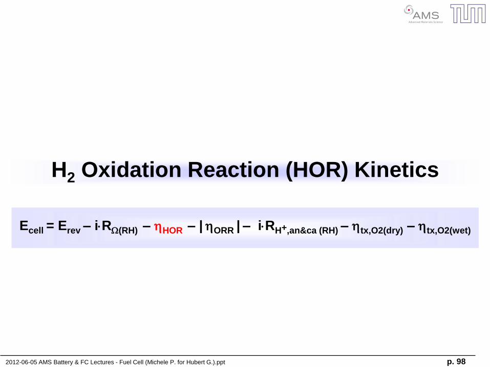
H2 Oxidation Reaction (HOR) Kinetics
Ecell = Erev – iRW(RH) – hHOR – | hORR | – iRH+,an&ca (RH) – htx,O2(dry) – htx,O2(wet)
2012-06-05 AMS Battery & FC Lectures - Fuel Cell (Michele P. for Hubert G.).ppt p. 99
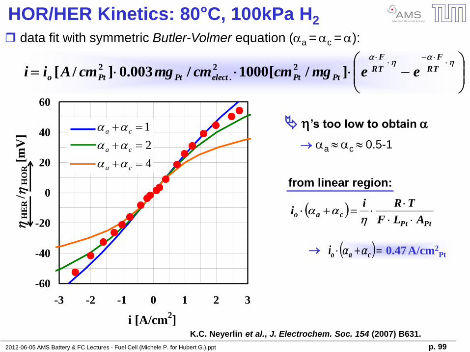
HOR/HER Kinetics: 80°C, 100kPa H2
PtPt
caoALF
TRii
h
caoi 0.47 A/cm2Pt
K.C. Neyerlin et al., J. Electrochem. Soc. 154 (2007) B631.
data fit with symmetric Butler-Volmer equation (a = c = ):
from linear region:
h
h
RT
F
RT
F
PtPtelectPtPto eemgcmcmmgcmAii ]/[1000/003.0]/[22
.
2
h’s too low to obtain
a c 0.5-1
-60
-40
-20
0
20
40
60
-3 -2 -1 0 1 2 3
i [A/cm2]
hH
ER
/h
HO
R [
mV
]
4
2
1
ca
ca
ca
2012-06-05 AMS Battery & FC Lectures - Fuel Cell (Michele P. for Hubert G.).ppt p. 100
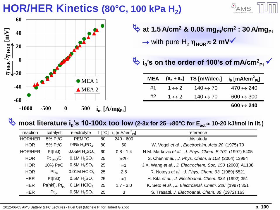
HOR/HER Kinetics (80°C, 100 kPa H2)
at 1.5 A/cm2 & 0.05 mgPt/cm2 : 30 A/mgPt
with pure H2 hHOR 2 mV
MEA (aa + ac) TS [mV/dec.] i0 [mA/cm2
Pt]
#1 1 2 140 70 470 240
#2 1 2 140 70 600 300
600 240-60
-40
-20
0
20
40
60
-1000 -500 0 500 1000im [A/mgPt]
hH
ER
/h
HO
R [
mV
]
MEA 1
MEA 2
i0’s on the order of 100’s of mA/cm2Pt
most literature i0’s 10-100x too low (2-3x for 2580°C for Eact 10-20 kJ/mol in lit.)
reaction catalyst electrolyte T [°C] i0 [mA/cm2
Pt] reference
HOR/HER 5% Pt/C PEMFC 80 240 - 600 this study
HOR 5% Pt/C 96% H3PO4 80 50 W. Vogel et al. , Electrochim. Acta 20 (1975) 79
HOR/HER Pt(hkl) 0.05M H2SO4 60 0.8 - 1.4 N.M. Markovic et al. , J. Phys. Chem. B 101 (1997) 5405
HOR Ptnano/C 0.1M H2SO4 25 20 S. Chen et al. , J. Phys. Chem. B 108 (2004) 13984
HOR 10% Pt/C 0.5M H2SO4 25 1 J.X. Wang et al. , J. Electrochem. Soc. 150 (2003) A1108
HOR Ptpc 0.01M HClO4 25 2.5 R. Notoya et al. , J. Phys. Chem. 93 (1989) 5521
HER Pt(hkl) 0.5M H2SO4 25 1 H. Kita et al. , J. Electroanal. Chem. 334 (1992) 351
HER Pt(hkl), Ptpc 0.1M HClO4 25 1.7 - 3.0 K. Seto et al. , J. Electroanal. Chem. 226 (1987) 351
HER Ptpc 0.5M H2SO4 25 3 S. Trasatti, J. Electroanal. Chem. 39 (1972) 163

2012-06-05 AMS Battery & FC Lectures - Fuel Cell (Michele P. for Hubert G.).ppt p. 101
O2 Reduction Reaction (ORR) Kinetics
Ecell = Erev – iRW(RH) – hHOR – | hORR | – iRH+,an&ca (RH) – htx,O2(dry) – htx,O2(wet)
2012-06-05 AMS Battery & FC Lectures - Fuel Cell (Michele P. for Hubert G.).ppt p. 102
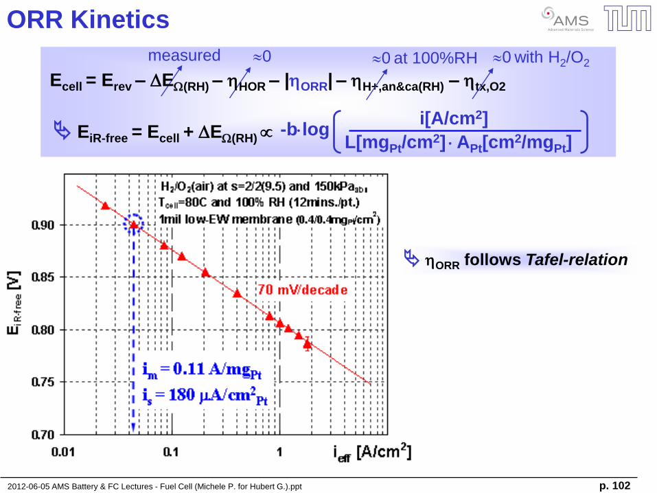
ORR Kinetics
0
Ecell = Erev – DEW(RH) – hHOR – |hORR| – hH+,an&ca(RH) – htx,O2
measured
-blog i[A/cm2]
L[mgPt/cm2] APt[cm2/mgPt] EiR-free = Ecell + DEW(RH)
0 at 100%RH 0 with H2/O2
hORR follows Tafel-relation
2012-06-05 AMS Battery & FC Lectures - Fuel Cell (Michele P. for Hubert G.).ppt p. 103
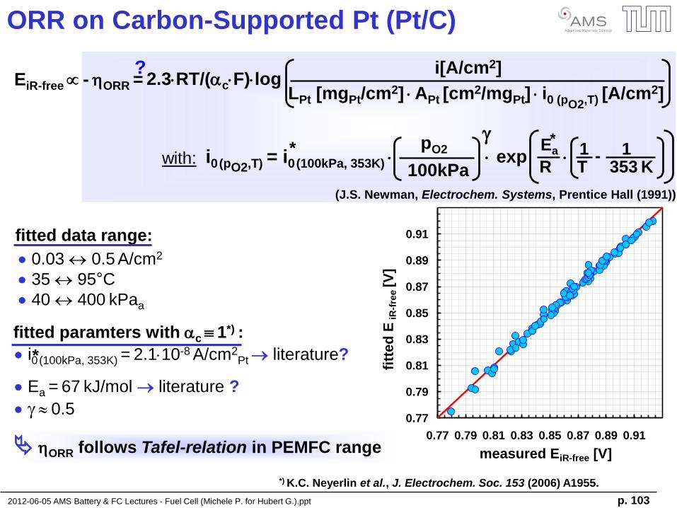
ORR on Carbon-Supported Pt (Pt/C)
2.3RT/(cF)log i[A/cm2]
LPt [mgPt/cm2] APt [cm2/mgPt] i0 (pO2,T) [A/cm2]
EiR-free - hORR = ?
with: i0 (pO2,T) = i0 (100kPa, 353K) * pO2
100kPa
g Ea
R
exp
* 1
T
1
353 K
-
(J.S. Newman, Electrochem. Systems, Prentice Hall (1991))
fitted data range:
0.03 0.5 A/cm2
35 95°C
40 400 kPaa
fitted paramters with c 1*) :
i0 (100kPa, 353K) = 2.110-8 A/cm2Pt literature?
Ea = 67 kJ/mol literature ?
g 0.5
*
hORR follows Tafel-relation in PEMFC range
*) K.C. Neyerlin et al., J. Electrochem. Soc. 153 (2006) A1955.
0.77
0.79
0.81
0.83
0.85
0.87
0.89
0.91
0.77 0.79 0.81 0.83 0.85 0.87 0.89 0.91
measured EiR-free [V]
fitt
ed
E i
R-f
ree [V
]
2012-06-05 AMS Battery & FC Lectures - Fuel Cell (Michele P. for Hubert G.).ppt p. 104
Direct Methanol Fuel Cells (DMFCs)
2012-06-05 AMS Battery & FC Lectures - Fuel Cell (Michele P. for Hubert G.).ppt p. 105
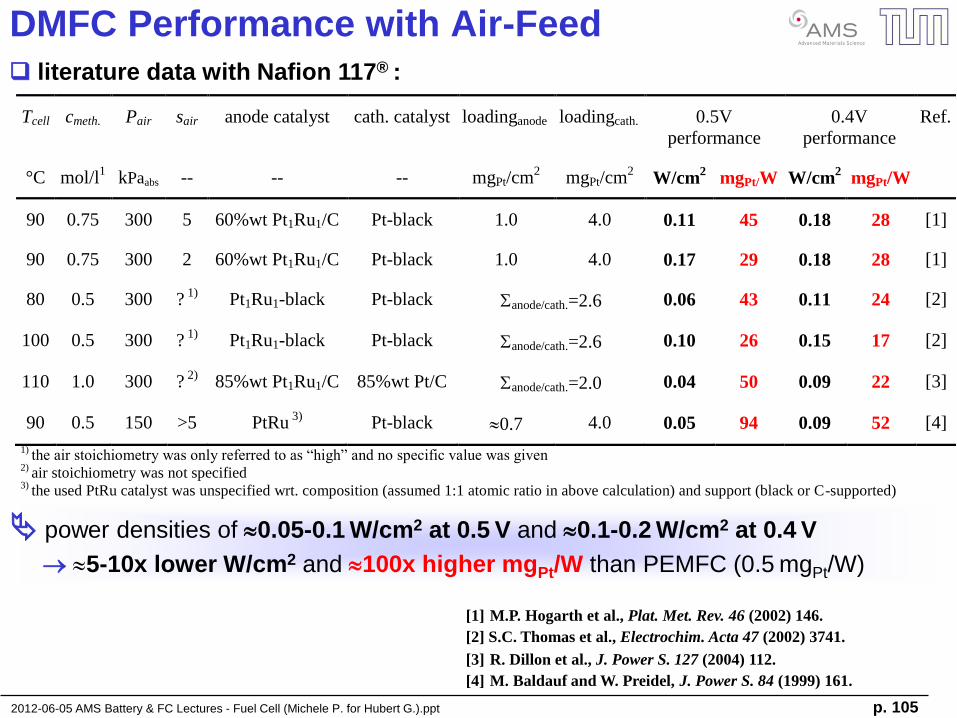
DMFC Performance with Air-Feed literature data with Nafion 117® :
[1] M.P. Hogarth et al., Plat. Met. Rev. 46 (2002) 146.
[3] R. Dillon et al., J. Power S. 127 (2004) 112.
[4] M. Baldauf and W. Preidel, J. Power S. 84 (1999) 161.
[2] S.C. Thomas et al., Electrochim. Acta 47 (2002) 3741.
power densities of 0.05-0.1 W/cm2 at 0.5 V and 0.1-0.2 W/cm2 at 0.4 V
5-10x lower W/cm2 and 100x higher mgPt/W than PEMFC (0.5 mgPt/W)
Tcell cmeth. Pair sair anode catalyst cath. catalyst loadinganode loadingcath. 0.5V
performance
0.4V
performance
Ref.
°C mol/l1 kPaabs -- -- -- mgPt/cm
2 mgPt/cm
2 W/cm
2 mgPt/W W/cm
2 mgPt/W
90 0.75 300 5 60%wt Pt1Ru1/C Pt-black 1.0 4.0 0.11 45 0.18 28 [1]
90 0.75 300 2 60%wt Pt1Ru1/C Pt-black 1.0 4.0 0.17 29 0.18 28 [1]
80 0.5 300 ? 1)
Pt1Ru1-black Pt-black anode/cath.=2.6 0.06 43 0.11 24 [2]
100 0.5 300 ? 1)
Pt1Ru1-black Pt-black anode/cath.=2.6 0.10 26 0.15 17 [2]
110 1.0 300 ? 2)
85%wt Pt1Ru1/C 85%wt Pt/C anode/cath.=2.0 0.04 50 0.09 22 [3]
90 0.5 150 >5 PtRu 3)
Pt-black 0.7 4.0 0.05 94 0.09 52 [4]
1) the air stoichiometry was only referred to as “high” and no specific value was given
2) air stoichiometry was not specified
3) the used PtRu catalyst was unspecified wrt. composition (assumed 1:1 atomic ratio in above calculation) and support (black or C-supported)
2012-06-05 AMS Battery & FC Lectures - Fuel Cell (Michele P. for Hubert G.).ppt p. 106
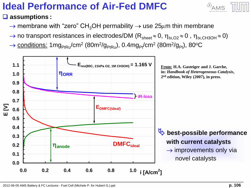
best-possible performance
with current catalysts
improvements only via
novel catalysts
Ideal Performance of Air-Fed DMFC assumptions :
membrane with “zero” CH3OH permability use 25mm thin membrane
no transport resistances in electrodes/DM (Rsheet 0, htx,O2 0 , htx,CH3OH 0)
conditions: 1mgPtRu/cm2 (80m2/gPtRu), 0.4mgPt/cm2 (80m2/gPt), 80oC
0.0
0.1
0.2
0.3
0.4
0.5
0.6
0.7
0.8
0.9
1.0
1.1
0.0 0.2 0.4 0.6 0.8 1.0 i [A/cm2]
E [
V]
iR-loss
hORR
hanode
EDMFC(ideal)
Erev(80C, 21kPa O2, 1M CH3OH) = 1.165 V
DMFCideal
From: H.A. Gasteiger and J. Garche,
in: Handbook of Heterogeneous Catalysis,
2nd edition, Wiley (2007), in press.
2012-06-05 AMS Battery & FC Lectures - Fuel Cell (Michele P. for Hubert G.).ppt p. 107
Electrochemistry Basics
- electrochemical cells & ion transport
- electrochemical potential
- half-cell reactions
Lithium Ion Batteries (LiBs)
- battery materials
- application of batteries
- “post-LiBs”
Fuel Cell Basics & Applications
- fuel cell types and materials
- basic electrocatalysis
- H2 reduction & O2 reduction kinetics
- transport resistances
2012-06-05 AMS Battery & FC Lectures - Fuel Cell (Michele P. for Hubert G.).ppt p. 108
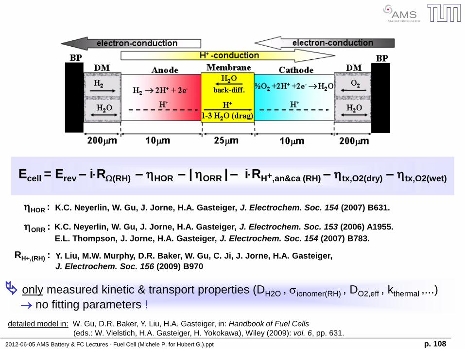
Ecell = Erev – iRW(RH) – hHOR – | hORR | – iRH+,an&ca (RH) – htx,O2(dry) – htx,O2(wet)
detailed model in: W. Gu, D.R. Baker, Y. Liu, H.A. Gasteiger, in: Handbook of Fuel Cells
(eds.: W. Vielstich, H.A. Gasteiger, H. Yokokawa), Wiley (2009): vol. 6, pp. 631.
only measured kinetic & transport properties (DH2O , sionomer(RH) , DO2,eff , kthermal ,...)
no fitting parameters !
K.C. Neyerlin, W. Gu, J. Jorne, H.A. Gasteiger, J. Electrochem. Soc. 153 (2006) A1955.
K.C. Neyerlin, W. Gu, J. Jorne, H.A. Gasteiger, J. Electrochem. Soc. 154 (2007) B631.
E.L. Thompson, J. Jorne, H.A. Gasteiger, J. Electrochem. Soc. 154 (2007) B783.
Y. Liu, M.W. Murphy, D.R. Baker, W. Gu, C. Ji, J. Jorne, H.A. Gasteiger,
J. Electrochem. Soc. 156 (2009) B970
hHOR :
hORR :
RH+,(RH) :
2012-06-05 AMS Battery & FC Lectures - Fuel Cell (Michele P. for Hubert G.).ppt p. 109
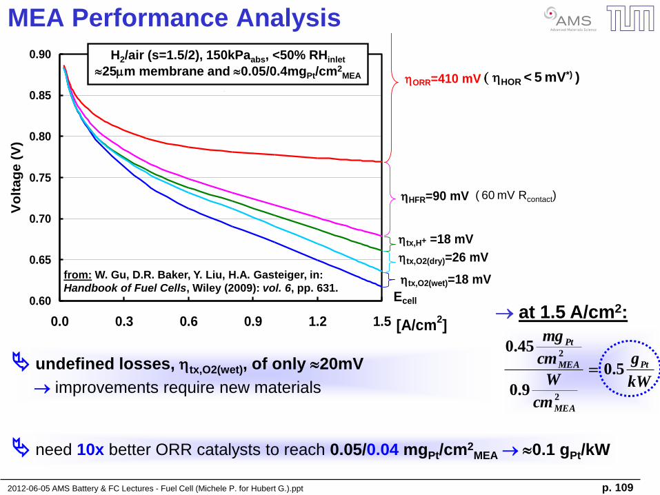
MEA Performance Analysis
0.60
0.65
0.70
0.75
0.80
0.85
0.90
0.0 0.3 0.6 0.9 1.2 1.5 [A/cm2]
Vo
ltag
e (
V)
Ecell
hHFR=90 mV (hmem=30 mV)
ST19-S0559 (Nano-x coating) RC FCPM op-line
MEA: Gore 5720 (18 mm, 0.2/0.3 mgPt/cm2, I/C=1.2)
DM/MPL: Pre-compressed SGL 25BC
htx,O2(dry)=26 mV
hORR=410 mV
htx,H+ =18 mV
htx,O2(wet)=18 mV
kW
g
cm
W
cm
mg
Pt
MEA
MEA
Pt
5.0
9.0
45.0
2
2
at 1.5 A/cm2:
H2/air (s=1.5/2), 150kPaabs, <50% RHinlet
25mm membrane and 0.05/0.4mgPt/cm2MEA
( 60 mV Rcontact)
undefined losses, htx,O2(wet), of only 20mV
improvements require new materials
need 10x better ORR catalysts to reach 0.05/0.04 mgPt/cm2MEA 0.1 gPt/kW
from: W. Gu, D.R. Baker, Y. Liu, H.A. Gasteiger, in:
Handbook of Fuel Cells, Wiley (2009): vol. 6, pp. 631.
hHOR < 5 mV*) )