Embed Size (px)
Citation preview

Electrochemical biosensors II: Amperometric biosensors
Lecture 2

Amperometric Sensors: Problem formulation• amperometric techniques have some selectivity as every RedOx reaction
has it’s own characteristic potential
-0.76
-0.40
-0.34
-0.34
-0.13
+0.16
E0, V
2Cu e Cu+ ++ →
2 2Pb e Pb+ + →
2 2Tl e Tl+ + →
3 3In e In+ + →
2 2Cd e Cd+ + →2 2Zn e Zn+ ++ →

Electrode Reactions
• Current:– Faradaic current: current associated with Oxidation/Reduction of
species of interestA Be+ →
CI dECA dt
′=
– Capacitive current: charging of double layer
– Other background currents due to presence of other speciese.g. oxygen

Electrode Reactions• Faradaic current:
A Bne+ →
rate of arrival of A = 1/n rate of e-transfer = rate of departure
A
B
ne
electrode
1A B
IJ Jn AF
− = =
• Possible limiting steps:– electron transfer– mass transport

The rate of charge transfer
• First order reactionOx Redeν −+ →
the rate of reduction: [ ]Ox cv k Ox=
the rate of oxidation: [ ]Red Redav k=
[ ]c cj Fk Oxν=
[ ]a Redaj Fkν=
[ ] [ ]a Red Oxc a cj j j Fk Fkν ν= − = −
• The activation Gibbs energy/G RTk Be
∗−∆=
[ ] [ ]/ /Red Oxa cG RT G RTa a c aj Fk B e Fk B eν ν
∗ ∗−∆ −∆= −
both processes involve activation

The Butler-Volmer equation• Reduction reaction
(0)c cG G F φ∗ ∗∆ = ∆ + ∆
Ox Redeν −+ →
transition state is product like:
(0)c cG G∗ ∗∆ ≈ ∆transition state is reagent like:
(0)c cG G Fα φ∗ ∗∆ = ∆ + ∆cathodic transfer coefficientusually approx. 0.5
• Oxidation reaction(0)c cG G F φ∗ ∗∆ = ∆ − ∆
Red Oxeν −− →
transition state is product like:
(0)c cG G∗ ∗∆ ≈ ∆transition state is reagent like:
(0) (1 )c cG G Fα φ∗ ∗∆ = ∆ − − ∆
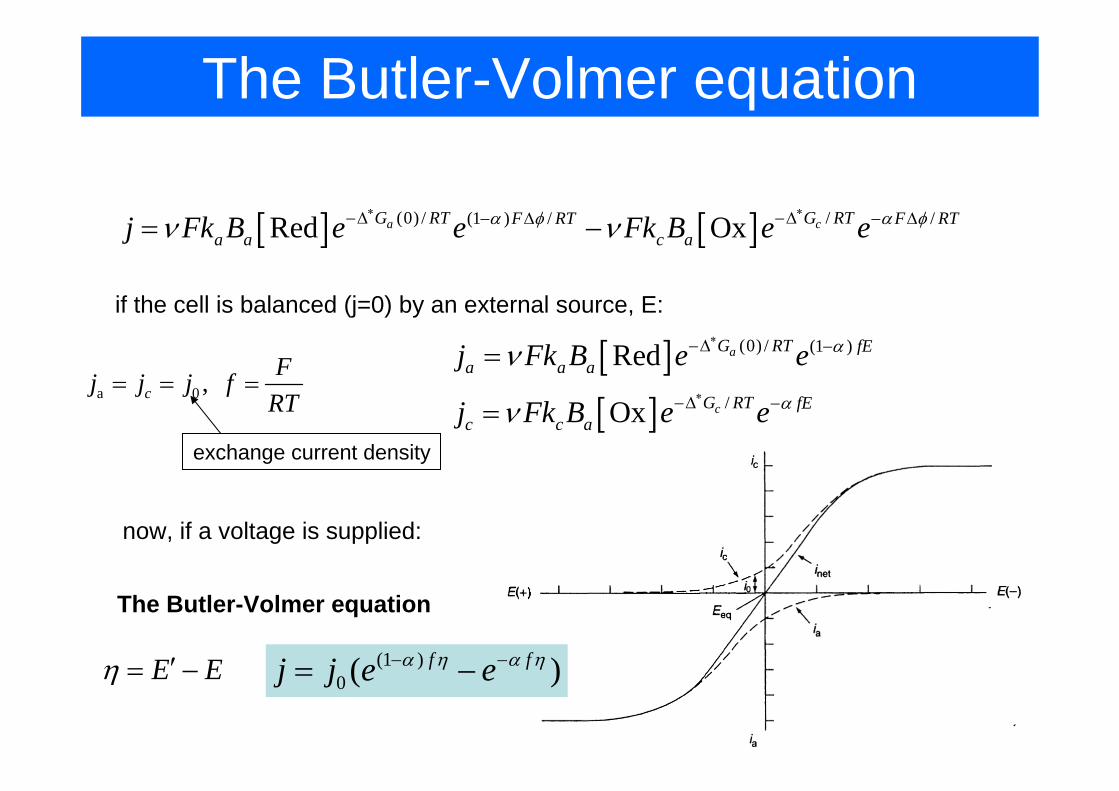
The Butler-Volmer equation
[ ] [ ](0) / /(1 ) / /Red Oxa cG RT G RTF RT F RTa a c aj Fk B e e Fk B e eα φ α φν ν
∗ ∗−∆ −∆− ∆ − ∆= −
if the cell is balanced (j=0) by an external source, E:
[ ][ ]
(0) / (1 )
/
Red
Ox
a
c
G RT fEa a a
G RT fEc c a
j Fk B e e
j Fk B e e
α
α
ν
ν
∗
∗
−∆ −
−∆ −
=
=a 0 ,c
Fj j j fRT
= = =
exchange current density
now, if a voltage is supplied:
E Eη ′= −
The Butler-Volmer equation
(1 )0 ( )f fj j e eα η α η− −= −

The Butler-Volmer equation
• The low overpotential limit
(1 )0 ( )f fj j e eα η α η− −= −
1, in practice 0.01Vfη η <
0 0(1 (1 ) ... 1 ...)j j f f j fα η α η η= + − + − − − ≈
0
jj f
η ≈ Ohm’s law
• The high overpotential limit in practice 0.12Vη ≥
(1 )0
fj j e α η−=positive overpotential:
0fj j e α η−=negative overpotential:
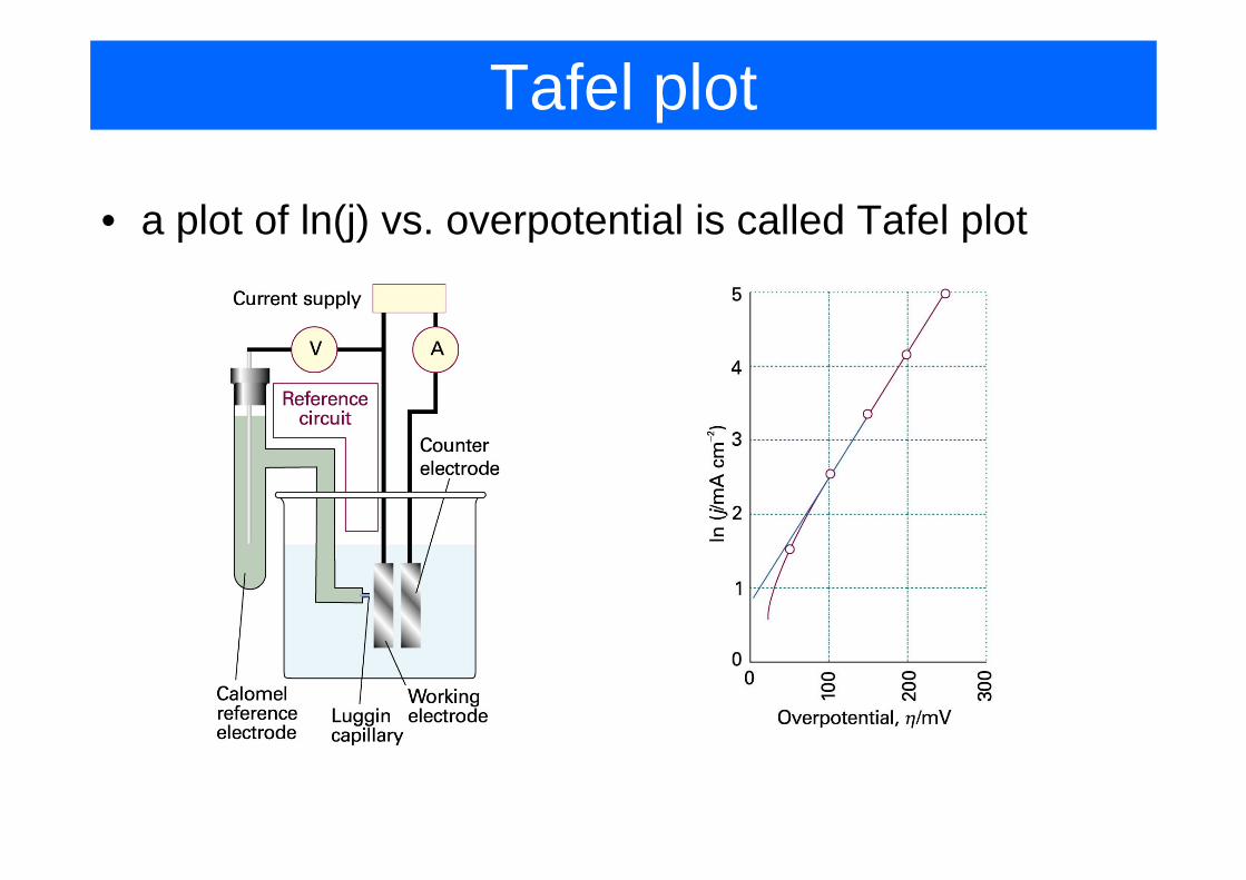
Tafel plot
• a plot of ln(j) vs. overpotential is called Tafel plot

Electrode Reactions• Mass transport modes:
– Diffusion: spontaneous movement due to concentration gradient
– Convection: transport by gross physical movement, e.g. stirring or flowing the solution, or rotating/vibrating the electrode
– Migration: movement of charged particles
( , ) ( , )1( , ) ( , ) ( , )C x t zFDC x tJ x t D C x t V x tx RT x
φ∂ ∂= − − +
∂ ∂

Mass transport mechanisms
• Migration (for ions) in response to a gradient of potential
• Diffusion in response to a concentration gradient
• Convection in response to pressure gradient
[ ]cJ A v=
[ ]d A
AJ D
x∂
= −∂
[ ]im i
i
z F EJ D iRT x− ∂
=∂∑

Voltammetry
• concentration polarization
non-polarizable electrodes: potential changes only slightly with current,polarizable electrodes: potential changes significantly with currentreference electrodes are highly non-polarizable
phenomena related to consumption of the reactive species on the electrode
0 0
0
ln ln ln
ln
RT RT RTE E a E czF zF zFRTE E czF
γ= + = + +
= +
at zero current:
with current: 0 lnRTE E czF
′ ′= +
lnc RT cE EzF c
η′⎛ ⎞′= − = ⎜ ⎟
⎝ ⎠

Voltammetry• concentration polarization
lnc RT cE EzF c
η′⎛ ⎞′= − = ⎜ ⎟
⎝ ⎠
First Fick’s law: c c cJ D Dx
c cj zFJ zFD
δ
δ
′∂ −⎛ ⎞= − =⎜ ⎟∂⎝ ⎠′−
= =
limiting current densitylim
c cRTj zFDzF
λδ δ
= =
using Nernst-Einstein equation,l – ionic conductivity
ln 1c RT jzF zcFD
δη ⎛ ⎞= −⎜ ⎟⎝ ⎠
conc. overpotential vs current:

Potential step experiment
• Experiment: potential is increased stepwise to some value, only O is initially present.
O ne R+ →
( , ) ( ) 14O O
O
xC x t C b erfD t
⎡ ⎤⎛ ⎞= −⎢ ⎥⎜ ⎟⎜ ⎟⎢ ⎥⎝ ⎠⎣ ⎦
• in a planar geometry:
( )4O
O
C bCx D t
∂=
∂
( )( ) ( )4O
OO
C bCJ t D i t nFADx D t
∂= − ⇒ =
∂Cottrell equation

Potential step experiment
2
2
( , ) 2C x t C CDt r r r
⎡ ⎤∂ ∂ ∂= +⎢ ⎥∂ ∂ ∂⎣ ⎦
• At a spherical electrode the situation is different as the diffusion equation will have another term:
( ) ( )( )4O O
O OO
C b C bi t nFAD nFADrD t
= +
Time independent term
• This leads to unique transport properties of microelectrodes (due to their small radius)

Chronoamperometry
• The potential is stepped to E2>Ep, current is monitored as a function of time
current decay due to mass transfer limitation
limiting value:½
oxnFAD Ciδ
=

Potential sweep experimentsCurrent raise,dominated by the drop in C0(0,t)
Current drop,dominated by the increase in d.
On microelectrodes we expect sigmoidal chape

Potential sweep experiment
• In the case of stirring, the distance d is maintained;
• The voltammogram will be sigmoidal in the case of stirring
• In aqueous solution distance d is typically 10-50µm for electrode rotation and 100-150 µm for solution stirring

Voltammetry
• linear sweep voltammetry
• differential pulse voltammetry
• cyclic voltammetry
current difference before and after pulse is measured
potential is applied in a sawtooth manner
• Linearly varied potential is applied between working electrode and reference electrode while current is monitored• current maximum is proportional to the concentration

Voltammetry: Example
• electro reduction of p-bromonitrobenzene
6 4 2 6 4 2
6 4 2 6 4 2
6 4 2 6 4 2
6 4 2 6 5 2
BrC H NO e BrC H NO
BrC H NO C H NO Br
C H NO e C H NO
C H NO H C H NO
− −
− −
− −
− +
+ ⎯⎯→
⎯⎯→• +
• + ⎯⎯→
+ ⎯⎯→
forward
backward fast
backward slow

Electrical double layer
• IHP – Inner Helmholz plane: specifically adsorbed ions• OHP – Outer Helmholz plane closest approach of
solvated ions
Exponential decay

Electrical double layer• Capacitance of the double layer
CH CG
( )1/ 1/ 1/dl H G
dl pzc
C C C
q C A E E
= +
= −
• For concentrate solutions, 1/CH>>1/CG and the capacitance is dominated by the Helmholz layer
• For diluted solutions CG is very small and C~CG.

Electrical double layer
• Current due to charging of double layer limits detectability of the potential controlled techniques
( ) ( ) dldl dl pzc pzc
dCdq dE dAi C A C E E A E Edt dt dt dt
= = + − + −

Electrical double layer• Electrocapillary effect
P const
qEγ
=
∂⎛ ⎞ =⎜ ⎟∂⎝ ⎠
Lippman equation2
2 dlP const
CEγ
=
⎛ ⎞∂= −⎜ ⎟∂⎝ ⎠
No electrostatic repulsion,max of surface tension
No electrostatic repulsion,max of surface tension

Linear Sweep Voltammetry (LSW)
• Linearly varied potential is applied between working electrode and reference electrode while current is monitored.
Background current
Ip~[Ox]
Ip

Kinetic and Catalytic Effects• usually, there is another chemical reaction coupled to the electron
transfer– consumption of reduced product
–regeneration of the oxidized reagentof the oxidized reagent
Voltammogram of ferrocene
w.glucose+GOX
w. glucose
forward
backward fast
backward slow

Amperometric Sensors• amperometric techniques have some selectivity as every RedOx reaction
has it’s own characteristic potential• however the selectivity is limited unless modified electrodes are used
Differential pulse polarogram for a mixture of six cations

Amperometric Biosensors
• First Generation – oxygen electrode based sensors• Second Generation – mediator based sensors• Third Generation – directly coupled enzyme
electrodes

Possible glucose detection schemes
1st generationschemes 2nd generation
schemes
3rd generationschemes

oxygen electrode based sensors
Electrolyte gel
Pt catode
Ag anode
Teflon membrane
Glucose oxidase on nylon net
Cellophane membrane
O-rings
Clark’s electrode


Measuring oxygen:
E=-0.7V
E=+0.65V
Measuring hydrogen peroxide:
Problems: fairly high potential (interference is probable), oxygen needs to be controlled and replenished (e.g. By oxygen generating reaction or by pumping oxygen containing buffer)
Problem: still fairly high potential (interference from e.g. ascorbic asid)

Mediator Based Sensors
• Oxygen is substituted with another oxidizing agent (electron transfer agent)
• Iron ions or complexes are most common mediators
Fc

Free Fe3+ are subject to hydrolysis and precipitation


Good Mediator
• Rapid reaction with enzyme• Fast electron transfer kinetics• Low overpotential• Independent of pH• Stable in Ox and R forms• Doesn’t react with oxygen• Non toxic

Fc derivatives

Various mediators (natural and artificial)

How it works...
Fc+glucose
Fc+glucose+GOD
In real biosensors both GOD and Fc are immobilised

Directly Coupled Enzyme
• Generally, the enzyme might denature on the electrode surface;
• electron transfer reaction might be slow • Thus, the surface has to be modified...
• Enzymes can be directly wired to the electrode using organic conducting salts (e.g.TTF/TCNQ) or redox polymers
• Enzymes can be modified to facilitate electron transfer and attachement

Possible glucose detection schemes

Design example: Glucose sensor
• Aim: for use by patient at home (should be simple, reliable and cheap)
• Performance: blood glucose range 1.1-33.3 mM; precision 3-8%; test time 30s; life time 6 month.
• Selective element: Glucose Oxidase – inexpensive, stable over long period
• Transducer: Amperometric (GOD+Fc) – cheap, reliable, easy read-out with LCD.
• Immobilisation: covalent bonding for long life (graphite foil coated with Fc, GOD immobilised)

ExacTech Glucose Sensor

Problems
• The transfer coefficient of a certain electrode in contact with M2+ and M3+ in aqueous solution at 25°C is 0.55. The current density is found to be 14.0 mA·cm-2 when the overvoltage is 130 mV. What is the overvoltage required for a current density of 85 mA·cm-2 ?