Embed Size (px)
Citation preview
ElectroabsorptionModulators
R. Sankaralingam
EE 698
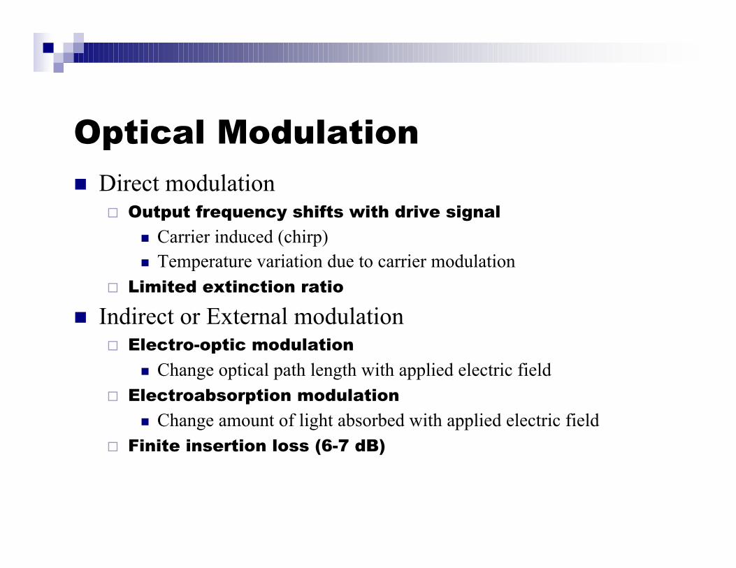
Optical Modulationn Direct modulation
® Output frequency shifts with drive signal
n Carrier induced (chirp)n Temperature variation due to carrier modulation
® Limited extinction ratio
n Indirect or External modulation® Electro-optic modulation
n Change optical path length with applied electric field® Electroabsorption modulation
n Change amount of light absorbed with applied electric field® Finite insertion loss (6-7 dB)
Advantages of EA modulator
n Zero biasing voltage
n Low driving voltage
n Low/negative chirp
n High speed
n Lesser polarization dependence
n Integration with DFB laser
n Allows a single optical power source to be used for largenumber of information carrying beams
Electroabsorption modulator
n Mechanisms® Franz-Keldysh effect
n Observed in conventional bulk semiconductors® Quantum-confined Stark effect (QCSE)
n Quantum well structures
n Both of these electroabsorption effects areprominent near the bandgap of semiconductors
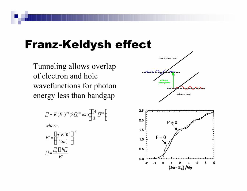
Franz-Keldysh effect
Tunneling allows overlapof electron and holewavefunctions for photonenergy less than bandgap
†
a = K(E ' )1/ 2 (8b)-1 exp -43
b 3 / 2Ê Ë Á
ˆ ¯ ˜
where,
E ' = q 2E 2h2
2mr*
Ê
Ë Á
ˆ
¯ ˜
1/ 3
b =eg -hw
E '
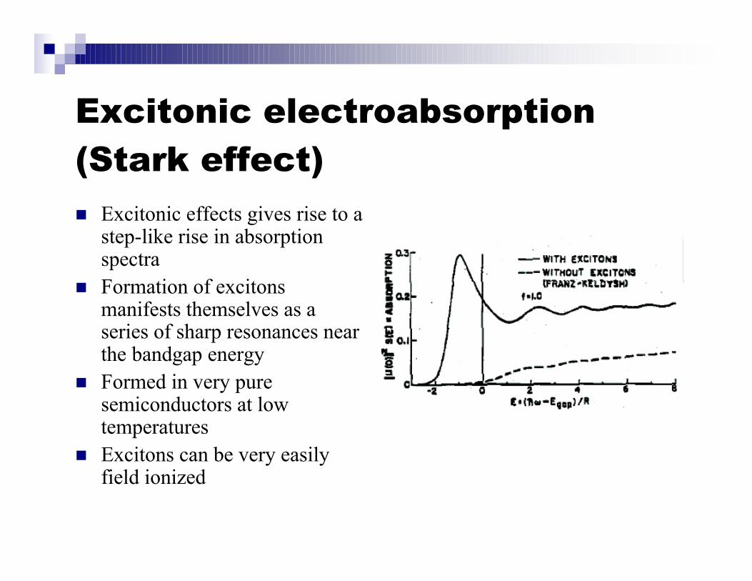
Excitonic electroabsorption(Stark effect)
n Excitonic effects gives rise to astep-like rise in absorptionspectra
n Formation of excitonsmanifests themselves as aseries of sharp resonances nearthe bandgap energy
n Formed in very puresemiconductors at lowtemperatures
n Excitons can be very easilyfield ionized
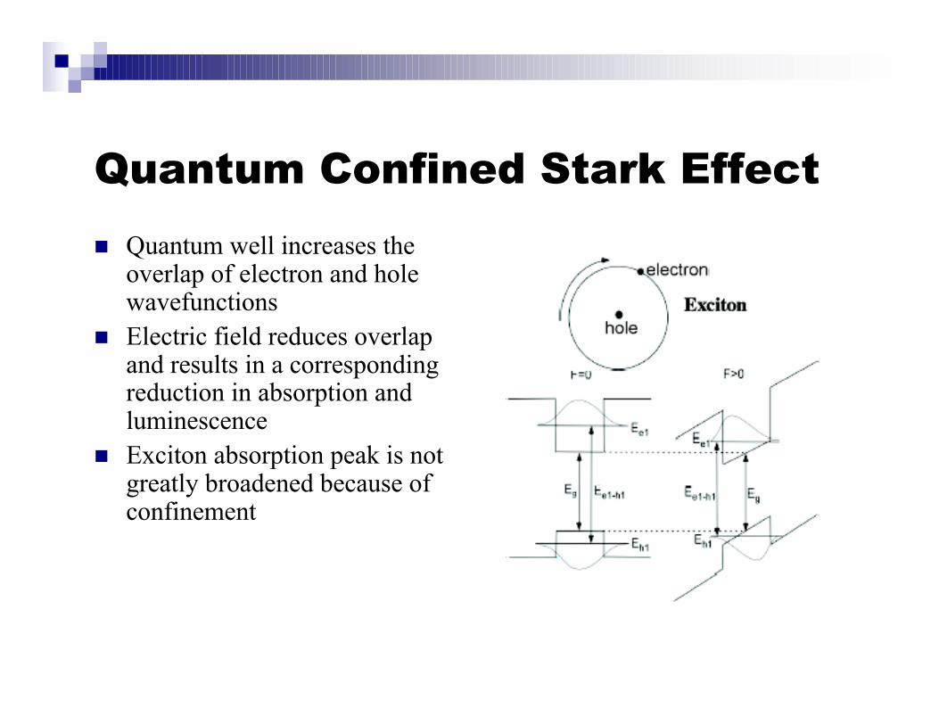
Quantum Confined Stark Effect
n Quantum well increases theoverlap of electron and holewavefunctions
n Electric field reduces overlapand results in a correspondingreduction in absorption andluminescence
n Exciton absorption peak is notgreatly broadened because ofconfinement
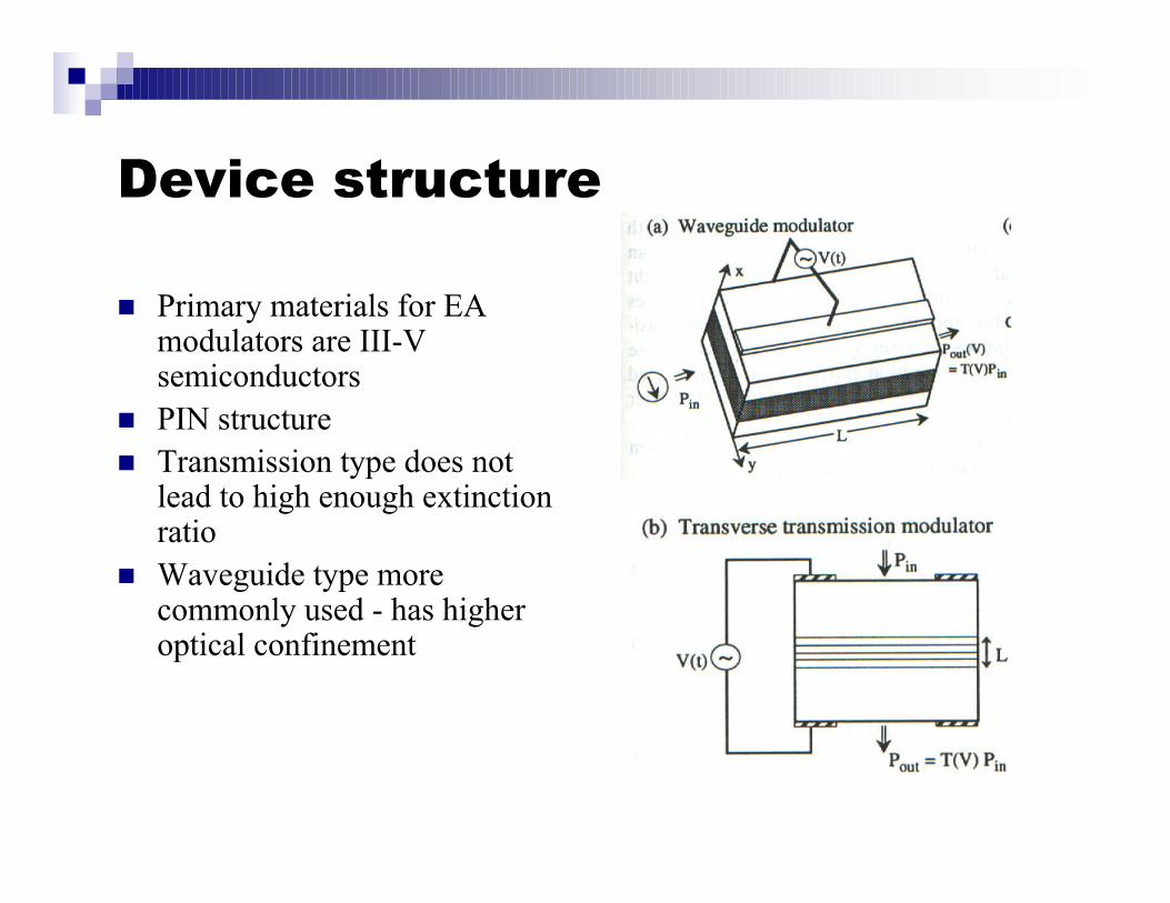
Device structure
n Primary materials for EAmodulators are III-Vsemiconductors
n PIN structuren Transmission type does not
lead to high enough extinctionratio
n Waveguide type morecommonly used - has higheroptical confinement
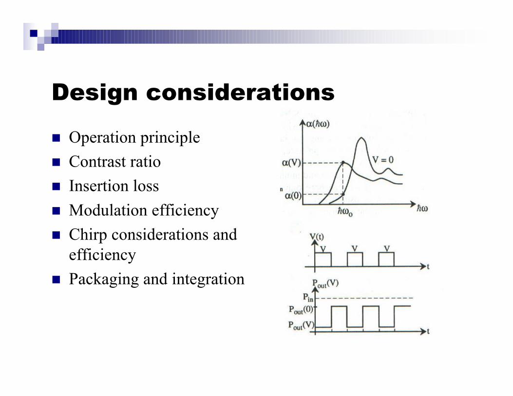
Design considerations
n Operation principle
n Contrast ratio
n Insertion loss
n Modulation efficiency
n Chirp considerations andefficiency
n Packaging and integration
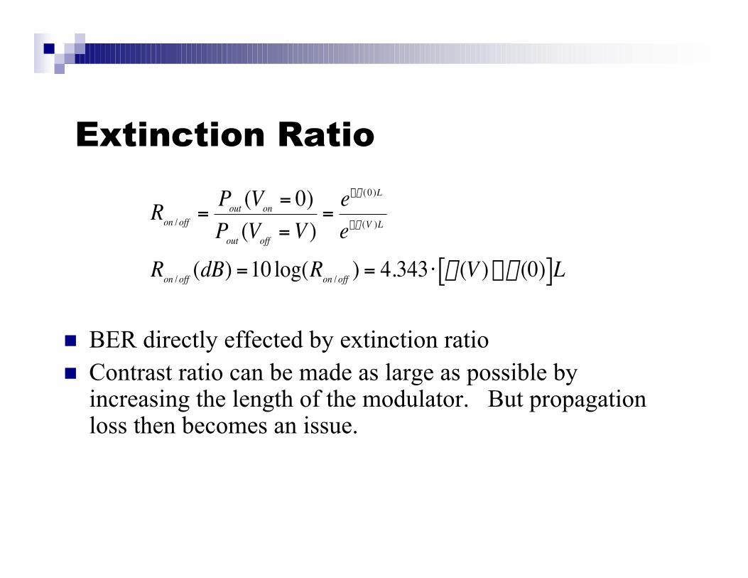
Extinction Ratio
n BER directly effected by extinction ration Contrast ratio can be made as large as possible by
increasing the length of the modulator. But propagationloss then becomes an issue.
†
Ron / off =Pout (Von = 0)Pout (Voff = V )
=e-a ( 0)L
e-a (V )L
Ron / off (dB) =10 log(Ron / off ) = 4.343 ⋅ a(V ) -a(0)[ ]L
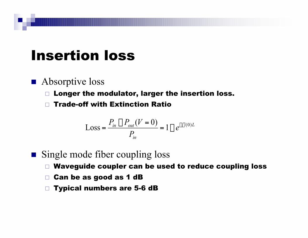
Insertion loss
n Absorptive loss® Longer the modulator, larger the insertion loss.
® Trade-off with Extinction Ratio
n Single mode fiber coupling loss® Waveguide coupler can be used to reduce coupling loss
® Can be as good as 1 dB
® Typical numbers are 5-6 dB
L
in
outin eP
VPP )0(1)0(
Loss a--==-
=
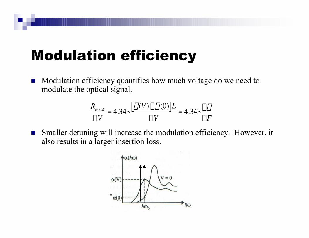
Modulation efficiency
n Modulation efficiency quantifies how much voltage do we need tomodulate the optical signal.
n Smaller detuning will increase the modulation efficiency. However, italso results in a larger insertion loss.
†
Ron / off
DV= 4.343
a(V ) -a(0)[ ]LDV
= 4.343 DaDF
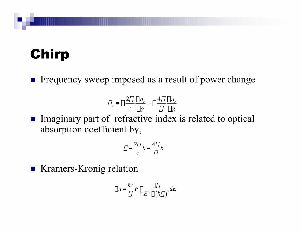
Chirp
n Frequency sweep imposed as a result of power change
n Imaginary part of refractive index is related to opticalabsorption coefficient by,
n Kramers-Kronig relation
†
a e ≡ -2wc
Dnr
Dg= -
4pl
Dnr
Dg
†
a =2wc
k =4pl
k
†
Dn =hcp
P DaE 2 - hw( )2
0
•
Ú dE
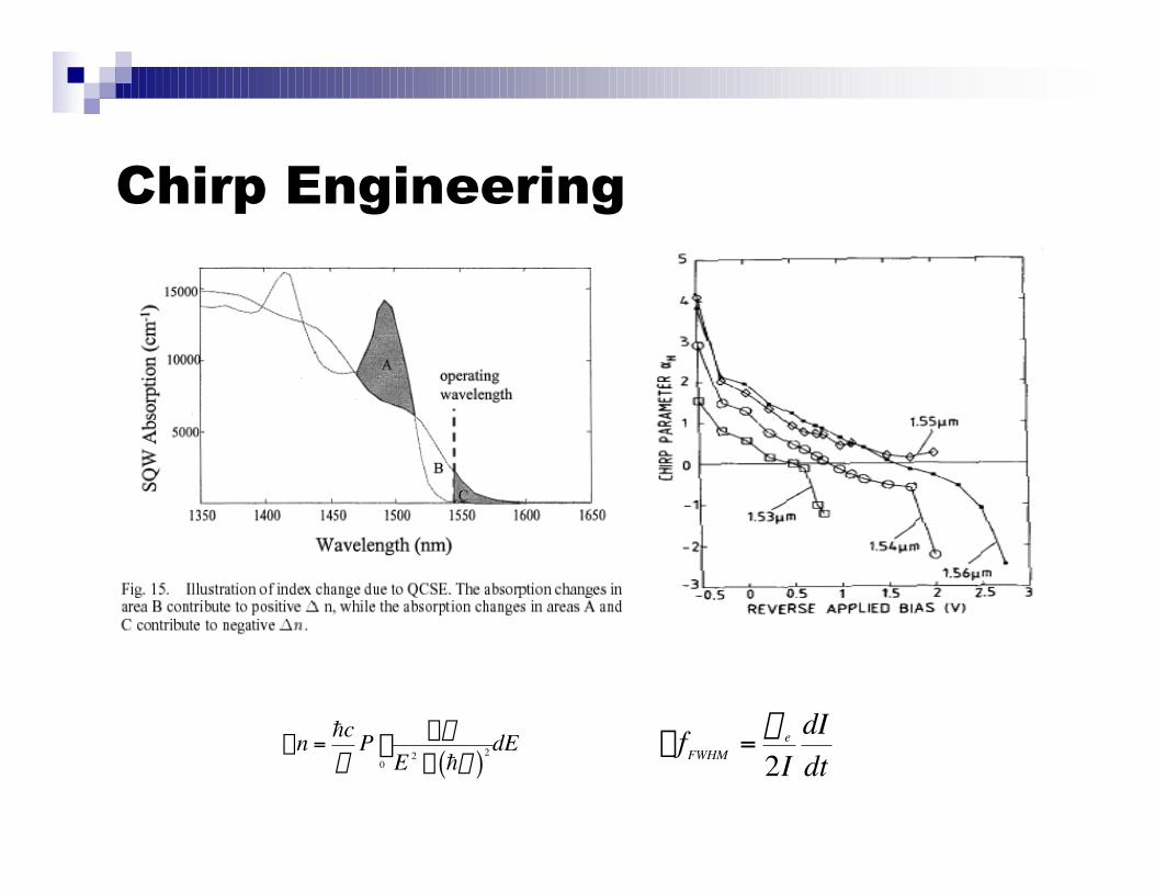
Chirp Engineering
†
DfFWHM =a e
2IdIdt
†
Dn =hcp
P DaE 2 - hw( )2
0
•
Ú dE
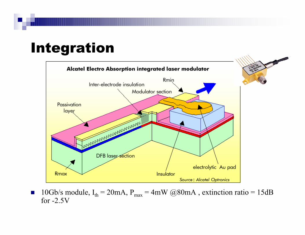
Integration
n 10Gb/s module, Ith = 20mA, Pmax = 4mW @80mA , extinction ratio = 15dBfor -2.5V
Acknowledgement
n P. Bhattacharya, Semiconductor Optoelectronic Devices
n S. L. Chuang, Physics of Optoelectronic Devices
n C. J. Chang-Hasnain, UC Berkeley, class notes
n J. S. Harris, Stanford University, class notes
n G. L. Li and P. K. L. Yu, J. Lightwave Tech., Sep 2003