Embed Size (px)
Citation preview
Electricity and MagnetismLab 3
Ohm’s Law
Lana Sheridan
De Anza College
Oct 8, 2015
Overview
• Current in a circuit
• Resistance and resistivity
• Reading resistor markings
• Ammeters and voltmeters
• Ohm’s Law
Current and Potential Difference
Current is the flow of charge. Its symbol is I or i .
The units of current are Amps, A.
Potential difference is the potential energy of each charged object,divided by the object’s charge.
For now, think of it as the “pump” that drives the flow of charge.
Its symbol is V , and the units are Volts, V.
Current and Potential Difference 68326-2 E LECTR IC CU R R E NTPART 3
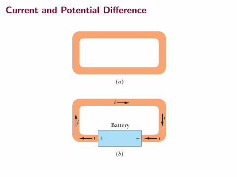
As Fig. 26-1a reminds us, any isolated conducting loop—regardless ofwhether it has an excess charge—is all at the same potential. No electric field canexist within it or along its surface. Although conduction electrons are available,no net electric force acts on them and thus there is no current.
If, as in Fig. 26-1b, we insert a battery in the loop, the conducting loop is nolonger at a single potential. Electric fields act inside the material making upthe loop, exerting forces on the conduction electrons, causing them to moveand thus establishing a current. After a very short time, the electron flowreaches a constant value and the current is in its steady state (it does not varywith time).
Figure 26-2 shows a section of a conductor, part of a conducting loop inwhich current has been established. If charge dq passes through a hypotheticalplane (such as aa!) in time dt, then the current i through that plane is defined as
(definition of current). (26-1)
We can find the charge that passes through the plane in a time intervalextending from 0 to t by integration:
(26-2)
in which the current i may vary with time.
q " ! dq " !t
0 i dt,
i "dqdt
Fig. 26-1 (a) A loop of copper inelectrostatic equilibrium.The entireloop is at a single potential, and theelectric field is zero at all points in-side the copper. (b) Adding a batteryimposes an electric potential differ-ence between the ends of the loopthat are connected to the terminalsof the battery.The battery thus pro-duces an electric field within theloop, from terminal to terminal, andthe field causes charges to movearound the loop.This movement ofcharges is a current i.
(a)
(b)
Battery
+ – ii
i
ii
Fig. 26-2 The current ithrough the conductor hasthe same value at planesaa!, bb!, and cc!.
i i
a
a'
b
b'
c
c'
The current is the same in any cross section.
Under steady-state conditions, the current is the same for planes aa!, bb!, andcc! and indeed for all planes that pass completely through the conductor, nomatter what their location or orientation.This follows from the fact that charge isconserved. Under the steady-state conditions assumed here, an electron mustpass through plane aa! for every electron that passes through plane cc!. In thesame way, if we have a steady flow of water through a garden hose, a drop ofwater must leave the nozzle for every drop that enters the hose at the other end.The amount of water in the hose is a conserved quantity.
The SI unit for current is the coulomb per second, or the ampere (A), whichis an SI base unit:
1 ampere " 1 A " 1 coulomb per second " 1 C/s.
The formal definition of the ampere is discussed in Chapter 29.Current, as defined by Eq. 26-1, is a scalar because both charge and time in
that equation are scalars. Yet, as in Fig. 26-1b, we often represent a current withan arrow to indicate that charge is moving. Such arrows are not vectors, however,and they do not require vector addition. Figure 26-3a shows a conductor withcurrent i0 splitting at a junction into two branches. Because charge is conserved,the magnitudes of the currents in the branches must add to yield the magnitudeof the current in the original conductor, so that
i0 " i1 # i2. (26-3)
As Fig. 26-3b suggests, bending or reorienting the wires in space does not changethe validity of Eq. 26-3. Current arrows show only a direction (or sense) of flowalong a conductor, not a direction in space.
Fig. 26-3 The relation i0 " i1 # i2
is true at junction a no matter what theorientation in space of the three wires.Currents are scalars, not vectors.
i 0
a
i 1
i 2
(a)
(b)
a i 2
i1
i 0
The current into thejunction must equalthe current out(charge is conserved).
halliday_c26_682-704hr.qxd 7-12-2009 14:30 Page 683
Resistance
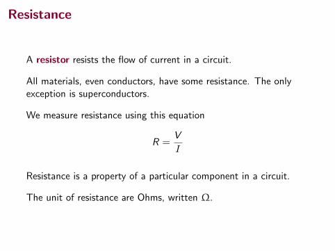
A resistor resists the flow of current in a circuit.
All materials, even conductors, have some resistance. The onlyexception is superconductors.
We measure resistance using this equation
R =V
I
Resistance is a property of a particular component in a circuit.
The unit of resistance are Ohms, written Ω.
Resistivity
Resistivity is a property of a material. Its symbol is ρ.
Resistivity
26-4 Resistance and ResistivityIf we apply the same potential difference between the ends of geometrically similarrods of copper and of glass, very different currents result. The characteristic of theconductor that enters here is its electrical resistance. We determine the resistancebetween any two points of a conductor by applying a potential difference V be-tween those points and measuring the current i that results.The resistance R is then
(definition of R). (26-8)
The SI unit for resistance that follows from Eq. 26-8 is the volt per ampere.This com-bination occurs so often that we give it a special name, the ohm (symbol !); that is,
(26-9)
A conductor whose function in a circuit is to provide a specified resistance iscalled a resistor (see Fig. 26-7). In a circuit diagram, we represent a resistor anda resistance with the symbol . If we write Eq. 26-8 as
we see that, for a given V, the greater the resistance, the smaller the current.The resistance of a conductor depends on the manner in which the potential
difference is applied to it. Figure 26-8, for example, shows a given potential dif-ference applied in two different ways to the same conductor. As the currentdensity streamlines suggest, the currents in the two cases—hence the measuredresistances—will be different. Unless otherwise stated, we shall assume that anygiven potential difference is applied as in Fig. 26-8b.
i "VR
,
" 1 V/A. 1 ohm " 1 ! " 1 volt per ampere
R "Vi
Fig. 26-8 Two ways of applying a potential difference to a conducting rod.The grayconnectors are assumed to have negligible resistance.When they are arranged as in(a) in a small region at each rod end, the measured resistance is larger than when theyare arranged as in (b) to cover the entire rod end.
(a) (b)
Fig. 26-7 An assortment of resistors.The circular bands are color-coding marksthat identify the value of the resistance.(The Image Works)
68926-4 R E S I STANCE AN D R E S I STIVITYPART 3
Table 26-1
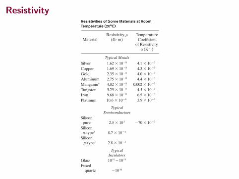
Resistivities of Some Materials at RoomTemperature (20°C)
Resistivity, r Temperature Material (! # m) Coefficient
of Resistivity,a (K$1)
Typical MetalsSilver 1.62 % 10$8 4.1 % 10$3
Copper 1.69 % 10$8 4.3 % 10$3
Gold 2.35 % 10$8 4.0 % 10$3
Aluminum 2.75 % 10$8 4.4 % 10$3
Manganina 4.82 % 10$8 0.002 % 10$3
Tungsten 5.25 % 10$8 4.5 % 10$3
Iron 9.68 % 10$8 6.5 % 10$3
Platinum 10.6 % 10$8 3.9 % 10$3
Typical Semiconductors
Silicon,pure 2.5 % 103 $70 % 10$3
Silicon,n-typeb 8.7 % 10$4
Silicon,p-typec 2.8 % 10$3
Typical Insulators
Glass 1010 $1014
Fused quartz !1016
aAn alloy specifically designed to have a small valueof a.bPure silicon doped with phosphorus impurities to acharge carrier density of 1023 m$3.cPure silicon doped with aluminum impurities to acharge carrier density of 1023 m$3.
As we have done several times in other connections, we often wish to take ageneral view and deal not with particular objects but with materials. Here we do soby focusing not on the potential difference V across a particular resistor but on theelectric field at a point in a resistive material. Instead of dealing with the current ithrough the resistor, we deal with the current density at the point in question.Instead of the resistance R of an object, we deal with the resistivity r of the material:
(definition of r). (26-10)
(Compare this equation with Eq. 26-8.)If we combine the SI units of E and J according to Eq. 26-10, we get, for the
unit of r, the ohm-meter (! # m):
(Do not confuse the ohm-meter, the unit of resistivity, with the ohmmeter, whichis an instrument that measures resistance.) Table 26-1 lists the resistivities ofsome materials.
unit (E)unit (J)
"V/mA/m2 "
VA
m " !#m.
& "EJ
J:
E:
halliday_c26_682-704hr.qxd 7-12-2009 14:30 Page 689
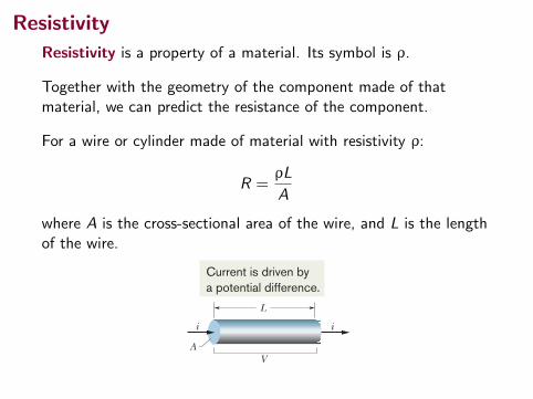
Resistivity
Resistivity is a property of a material. Its symbol is ρ.
Together with the geometry of the component made of thatmaterial, we can predict the resistance of the component.
For a wire or cylinder made of material with resistivity ρ:
R =ρL
A
where A is the cross-sectional area of the wire, and L is the lengthof the wire.
690 CHAPTE R 26 CU R R E NT AN D R E S I STANCE
Resistance is a property of an object. Resistivity is a property of a material.
CHECKPOINT 3
The figure here shows threecylindrical copper conductorsalong with their face areas andlengths. Rank them according tothe current through them, great-est first, when the same potential difference V is placed across their lengths.
(a) (b)
A
L
(c)
1.5LA_2
A_2
L/2
Fig. 26-9 A potential differenceV is applied between the ends of awire of length L and cross section A,establishing a current i.
L
i i
A V
Current is driven bya potential difference.
We can write Eq. 26-10 in vector form as
(26-11)
Equations 26-10 and 26-11 hold only for isotropic materials—materials whoseelectrical properties are the same in all directions.
We often speak of the conductivity s of a material.This is simply the recipro-cal of its resistivity, so
(definition of s). (26-12)
The SI unit of conductivity is the reciprocal ohm-meter, (! " m)#1. The unit namemhos per meter is sometimes used (mho is ohm backwards). The definition of sallows us to write Eq. 26-11 in the alternative form
(26-13)
Calculating Resistance from ResistivityWe have just made an important distinction:
J:
$ %E:
.
% $1&
E:
$ &J:
.
If we know the resistivity of a substance such as copper, we can calculate theresistance of a length of wire made of that substance. Let A be the cross-sectionalarea of the wire, let L be its length, and let a potential difference V exist betweenits ends (Fig. 26-9). If the streamlines representing the current density are uniformthroughout the wire, the electric field and the current density will be constant forall points within the wire and, from Eqs. 24-42 and 26-5, will have the values
E $ V/L and J $ i/A. (26-14)
We can then combine Eqs. 26-10 and 26-14 to write
(26-15)
However, V/i is the resistance R, which allows us to recast Eq. 26-15 as
(26-16)
Equation 26-16 can be applied only to a homogeneous isotropic conductor ofuniform cross section, with the potential difference applied as in Fig. 26-8b.
The macroscopic quantities V, i, and R are of greatest interest when we aremaking electrical measurements on specific conductors. They are the quantitiesthat we read directly on meters. We turn to the microscopic quantities E, J, and rwhen we are interested in the fundamental electrical properties of materials.
R $ & LA
.
& $EJ
$V/Li/A
.
halliday_c26_682-704hr.qxd 7-12-2009 14:30 Page 690
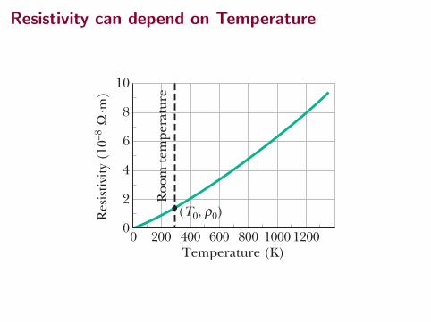
Resistivity can depend on Temperature69126-4 R E S I STANCE AN D R E S I STIVITY
PART 3
Variation with TemperatureThe values of most physical properties vary with temperature, and resistivity is noexception. Figure 26-10, for example, shows the variation of this property forcopper over a wide temperature range. The relation between temperature andresistivity for copper—and for metals in general—is fairly linear over a ratherbroad temperature range. For such linear relations we can write an empiricalapproximation that is good enough for most engineering purposes:
r ! r0 " r0a(T !T0). (26-17)
Here T0 is a selected reference temperature and r0 is the resistivity at that tem-perature. Usually T0 " 293 K (room temperature), for which r0 " 1.69 # 10!8
$ % m for copper.Because temperature enters Eq. 26-17 only as a difference, it does not matter
whether you use the Celsius or Kelvin scale in that equation because the sizes ofdegrees on these scales are identical. The quantity a in Eq. 26-17, called thetemperature coefficient of resistivity, is chosen so that the equation gives goodagreement with experiment for temperatures in the chosen range. Some values ofa for metals are listed in Table 26-1.
Fig. 26-10 The re-sistivity of copper as afunction of tempera-ture.The dot on thecurve marks a conve-nient reference point attemperature T0 " 293K and resistivity r0 "1.69 # 10!8 $ % m.
Roo
m te
mpe
ratu
re
200 400 600 800 1000 1200 Temperature (K)
Res
istiv
ity (
10–8
. m
) Ω
ρ (T0, 0)
10
8
6
4
2
0 0
Resistivity can dependon temperature.
Sample Problem
Calculations: For arrangement 1, we have L " 15 cm "0.15 m and
A " (1.2 cm)2 " 1.44 # 10!4 m2.
Substituting into Eq. 26-16 with the resistivity r from Table26-1, we then find that for arrangement 1,
3
(Answer)
Similarly, for arrangement 2, with distance L " 1.2 cmand area A " (1.2 cm)(15 cm), we obtain
(Answer) " 6.5 # 10 !7 $ " 0.65 &$.
R "'LA
"(9.68 # 10 !8 $%m)(1.2 # 10 !2 m)
1.80 # 10 !3 m2
" 1.0 # 10 !4 $ " 100 &$.
R "'L(
"(9.68 # 10 !8 $%m)(0.15 m)
1.44 # 10 !4 m2
A material has resistivity, a block of the material has resistance
A rectangular block of iron has dimensions 1.2 cm # 1.2cm # 15 cm. A potential difference is to be applied tothe block between parallel sides and in such a way thatthose sides are equipotential surfaces (as in Fig. 26-8b).What is the resistance of the block if the two parallelsides are (1) the square ends (with dimensions 1.2 cm #1.2 cm) and (2) two rectangular sides (with dimensions1.2 cm # 15 cm)?
The resistance R of an object depends on how the electricpotential is applied to the object. In particular, it dependson the ratio L/A, according to Eq. 26-16 (R " rL/A),where A is the area of the surfaces to which the potentialdifference is applied and L is the distance between thosesurfaces.
KEY I DEA
Additional examples, video, and practice available at WileyPLUS
halliday_c26_682-704hr.qxd 7-12-2009 14:30 Page 691
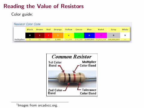
Reading the Value of Resistors
Color guide:
1Images from orcadxcc.org.
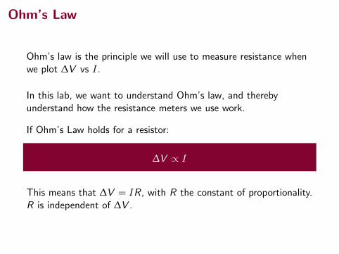
Ohm’s Law
Ohm’s law is the principle we will use to measure resistance whenwe plot ∆V vs I.
In this lab, we want to understand Ohm’s law, and therebyunderstand how the resistance meters we use work.
If Ohm’s Law holds for a resistor:
∆V ∝ I
This means that ∆V = IR, with R the constant of proportionality.R is independent of ∆V .
Current and Potential Difference in a Circuit
70927-5 OTH E R S I NG LE-LOOP CI RCU ITSPART 3
HALLIDAY REVISED
RESISTANCE RULE: For a move through a resistance in the direction of the current, the change in potential is !iR; in the opposite direction it is "iR.
EMF RULE: For a move through an ideal emf device in the direction of the emf arrow, the change in potential is "!; in the opposite direction it is !!.
CHECKPOINT 1
The figure shows the current i in a single-loop circuitwith a battery B and a resistance R (and wires ofnegligible resistance). (a) Should the emf arrow at Bbe drawn pointing leftward or rightward? At pointsa, b, and c, rank (b) the magnitude of the current, (c)the electric potential, and (d) the electric potentialenergy of the charge carriers, greatest first.
a b c B
i
R
27-5 Other Single-Loop CircuitsIn this section we extend the simple circuit of Fig. 27-3 in two ways.
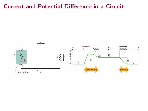
Internal ResistanceFigure 27-4a shows a real battery, with internal resistance r, wired to an externalresistor of resistance R. The internal resistance of the battery is the electricalresistance of the conducting materials of the battery and thus is an unremovablefeature of the battery. In Fig. 27-4a, however, the battery is drawn as if it could beseparated into an ideal battery with emf ! and a resistor of resistance r.The orderin which the symbols for these separated parts are drawn does not matter.
If we apply the loop rule clockwise beginning at point a, the changes inpotential give us
! ! ir ! iR # 0. (27-3)Solving for the current, we find
. (27-4)
Note that this equation reduces to Eq. 27-2 if the battery is ideal—that is, if r # 0.Figure 27-4b shows graphically the changes in electric potential around the
circuit. (To better link Fig. 27-4b with the closed circuit in Fig. 27-4a, imaginecurling the graph into a cylinder with point a at the left overlapping point a at
i #!
R " r
R i
i
i
Real battery
r
i
a
b +
–
(a)
Emf device Resistor
a b a
r
ir
Pote
ntia
l (V
)
R
i
iRVaVa
Vb
(b)
Fig. 27-4 (a) A single-loop circuit containing a real battery having internal resistancer and emf !. (b) The same circuit, now spread out in a line.The potentials encounteredin traversing the circuit clockwise from a are also shown.The potential Va is arbitrarilyassigned a value of zero, and other potentials in the circuit are graphed relative to Va.
halliday_c27_705-734v2.qxd 23-11-2009 14:35 Page 709
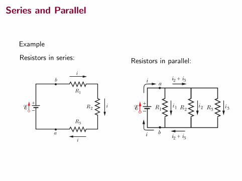
Series and Parallel
Example
Resistors in series:710 CHAPTE R 27 CI RCU ITS
HALLIDAY REVISED
the right.) Note how traversing the circuit is like walking around a (potential)mountain back to your starting point—you return to the starting elevation.
In this book, when a battery is not described as real or if no internal resistanceis indicated, you can generally assume that it is ideal—but, of course, in the realworld batteries are always real and have internal resistance.
Resistances in SeriesFigure 27-5a shows three resistances connected in series to an ideal battery withemf !. This description has little to do with how the resistances are drawn.Rather, “in series” means that the resistances are wired one after another andthat a potential difference V is applied across the two ends of the series. In Fig.27-5a, the resistances are connected one after another between a and b, and apotential difference is maintained across a and b by the battery. The potentialdifferences that then exist across the resistances in the series produce identicalcurrents i in them. In general,
Fig. 27-5 (a) Three resistors are con-nected in series between points a and b.(b) An equivalent circuit, with the threeresistors replaced with their equivalentresistance Req.
When a potential difference V is applied across resistances connected in series,the resistances have identical currents i. The sum of the potential differences acrossthe resistances is equal to the applied potential difference V.
Note that charge moving through the series resistances can move along only asingle route. If there are additional routes, so that the currents in different resis-tances are different, the resistances are not connected in series.
Resistances connected in series can be replaced with an equivalent resistance Req that hasthe same current i and the same total potential difference V as the actual resistances.
You might remember that Req and all the actual series resistances have the samecurrent i with the nonsense word “ser-i.” Figure 27-5b shows the equivalent resis-tance Req that can replace the three resistances of Fig. 27-5a.
To derive an expression for Req in Fig. 27-5b, we apply the loop rule to both circuits. For Fig. 27-5a, starting at a and going clockwise around the circuit, we find
! ! iR1 ! iR2 ! iR3 " 0,
or (27-5)
For Fig. 27-5b, with the three resistances replaced with a single equivalent resis-tance Req, we find
! ! iReq " 0,
or (27-6)
Comparison of Eqs. 27-5 and 27-6 shows that
Req " R1 # R2 # R3.
The extension to n resistances is straightforward and is
(n resistances in series). (27-7)
Note that when resistances are in series, their equivalent resistance is greaterthan any of the individual resistances.
Req " !n
j"1 Rj
i "!
Req.
i "!
R1 # R2 # R3.
CHECKPOINT 2
In Fig. 27-5a, if R1 $ R2 $ R3, rank thethree resistances according to (a) thecurrent through them and (b) the po-tential difference across them, greatestfirst.
+ –
a
b
i R 2
R3
R1
i
i
(a)
+–
a
b
iR eq
(b)
Series resistors and theirequivalent have the samecurrent (“ser-i”).
halliday_c27_705-734v2.qxd 23-11-2009 14:35 Page 710
Resistors in parallel:
714 CHAPTE R 27 CI RCU ITS
HALLIDAY REVISED
JUNCTION RULE: The sum of the currents entering any junction must be equal tothe sum of the currents leaving that junction.
Fig. 27-9 A multiloop circuit consistingof three branches: left-hand branch bad,right-hand branch bcd, and central branchbd.The circuit also consists of three loops:left-hand loop badb, right-hand loop bcdb,and big loop badcb.
This rule is often called Kirchhoff’s junction rule (or Kirchhoff’s current law). It issimply a statement of the conservation of charge for a steady flow of charge—there is neither a buildup nor a depletion of charge at a junction. Thus, our basictools for solving complex circuits are the loop rule (based on the conservation ofenergy) and the junction rule (based on the conservation of charge).
Equation 27-18 is a single equation involving three unknowns. To solve the cir-cuit completely (that is, to find all three currents), we need two more equations in-volving those same unknowns.We obtain them by applying the loop rule twice. In thecircuit of Fig. 27-9, we have three loops from which to choose: the left-hand loop(badb), the right-hand loop (bcdb), and the big loop (badcb). Which two loops wechoose does not matter—let’s choose the left-hand loop and the right-hand loop.
If we traverse the left-hand loop in a counterclockwise direction from pointb, the loop rule gives us
!1 ! i1R1 " i3R3 # 0. (27-19)
If we traverse the right-hand loop in a counterclockwise direction from point b,the loop rule gives us !i3R3 ! i2R2 ! !2 # 0. (27-20)
We now have three equations (Eqs. 27-18, 27-19, and 27-20) in the three unknowncurrents, and they can be solved by a variety of techniques.
If we had applied the loop rule to the big loop, we would have obtained(moving counterclockwise from b) the equation
!1 ! i1R1 ! i2R2 ! !2 # 0.
However, this is merely the sum of Eqs. 27-19 and 27-20.
Resistances in ParallelFigure 27-10a shows three resistances connected in parallel to an ideal battery of emf!.The term “in parallel” means that the resistances are directly wired together on oneside and directly wired together on the other side, and that a potential difference V isapplied across the pair of connected sides. Thus, all three resistances have the same potential difference V across them,producing a current through each.In general,
Fig. 27-10 (a) Three resistorsconnected in parallel across points aand b. (b) An equivalent circuit, withthe three resistors replaced withtheir equivalent resistance Req.
R 2 R3 R1
a b c
d
i 1 i 3 i 2
+ – 1 2
– +
The current into the junctionmust equal the current out(charge is conserved).
27-7 Multiloop CircuitsFigure 27-9 shows a circuit containing more than one loop. For simplicity, weassume the batteries are ideal. There are two junctions in this circuit, at b and d,and there are three branches connecting these junctions.The branches are the leftbranch (bad), the right branch (bcd), and the central branch (bd). What are thecurrents in the three branches?
We arbitrarily label the currents, using a different subscript for each branch.Current i1 has the same value everywhere in branch bad, i2 has the same valueeverywhere in branch bcd, and i3 is the current through branch bd. The directionsof the currents are assumed arbitrarily.
Consider junction d for a moment: Charge comes into that junction viaincoming currents i1 and i3, and it leaves via outgoing current i2. Because there isno variation in the charge at the junction, the total incoming current must equalthe total outgoing current:
i1 " i3 # i2. (27-18)
You can easily check that applying this condition to junction b leads to exactlythe same equation. Equation 27-18 thus suggests a general principle:
R3 R1
a
b
i 1 i 3 i 2 + – R 2
(a)
b
i R eq
(b)
a
i
+ –
i
i
i
i2 + i3
i2 + i3
Parallel resistors and theirequivalent have the samepotential difference (“par-V”).
halliday_c27_705-734v2.qxd 23-11-2009 14:35 Page 714
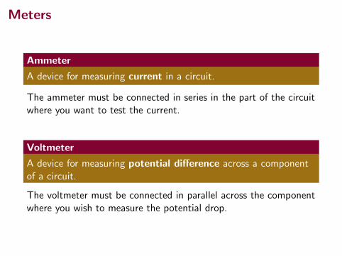
Meters
Ammeter
A device for measuring current in a circuit.
The ammeter must be connected in series in the part of the circuitwhere you want to test the current.
Voltmeter
A device for measuring potential difference across a componentof a circuit.
The voltmeter must be connected in parallel across the componentwhere you wish to measure the potential drop.
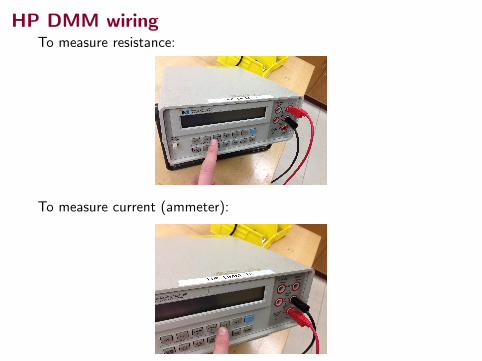
HP DMM wiringTo measure resistance:
To measure current (ammeter):
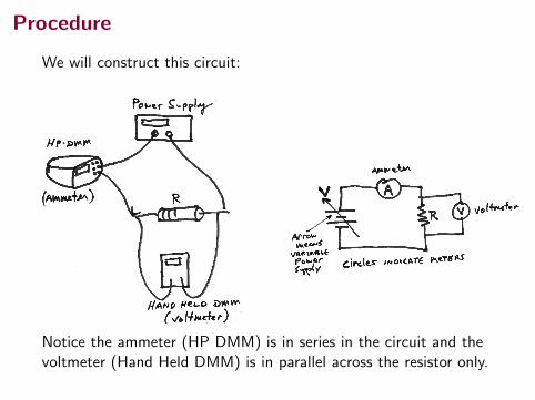
Procedure
We will construct this circuit:
Notice the ammeter (HP DMM) is in series in the circuit and thevoltmeter (Hand Held DMM) is in parallel across the resistor only.
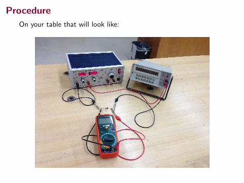
Procedure
On your table that will look like: