Embed Size (px)
Citation preview
Electrical Trade Specification Rev. AH 01.01.2018
GENERAL
a) BDW Trading Limited
Barratt Homes and David Wilson Homes are all trading names of BDW Trading Limited “the Company”.
b) Clearing The Contractor is responsible for clearing up and safe removing waste materials arising from execution of the Works, as part of this Trade Specification.
Waste materials must be removed as work progresses, ensuring that all waste materials have been removed following the completion of the works and taken to waste segregation area for sorting by subcontractor.
Failure to comply with this requirement resulting in the Company’s labour performing this task will result in contra charges.
c) Contract Conditions The Contractors attention is drawn to the Company’s Conditions of Contract and General Terms.
d) Defective Workmanship All defects arising from poor workmanship by the Contractor or, by the Contractor not carrying out the Works in accordance with this Trade Specification are to be remedied by the Contractor at no cost to the Company.
Failure by the Contractor to carry out this contractual obligation, resulting in an alternative Contractor being instructed to carry out such remedial work, will incur the Contractor with the cost thereof.
e) Governing Documents The documents below must be used for reference in compliance with the Company’s standard working drawings and construction best practice guide. The Contractor is to ensure that all current versions are followed.
All materials, equipment, accessories and workmanship shall fully comply with the latest edition of the I.E.T. Regulations for electrical installations and current amendments and shall be as specified in the schedule of materials including but not limited to:
Building Regulations Part L
Building Regulations Part M
Building Regulations Part P
I.E.T. Regulations
ELECTRICAL
TRADE SPECIFICATION
Electrical Trade Specification Rev. AH 01.01.2018
All manufacturers used must hold the current BS 5750: Part 2: 1979, ISO:9002/1987 or in the case of cables BASEC certification. It is the Contractors responsibility to certify that they have viewed a copy of the relevant certificates showing compliance.
All Electrical installation must be completed in accordance with BS 7671, BS 3456 and BS 3955.
f) Group Suppliers
The Contractor should be aware that the Company operates National Commodity
Agreements with a number of nominated suppliers, as listed below. It is the Contractors
responsibility to ensure that these agreements are adhered to. Failure to do so may lead to
the Company making a claim from the Contractor for any loss of rebate.
Electrical Accessories, Smoke Detectors and Downlights –
Deta Electrical Co Ltd Kingsway House Laporte Way Luton Bedfordshire LU4 8RJ
Consumer Units – Hager Ltd Hortonwood 50 Telford Shropshire TF1 7FT
Mechanical Ventilators, Ducts and Terminations –
EnviroVent Ltd
EnviroVent House Hornbeam Business Park Hookstone Road Harrogate HG2 8PA
External Lighting – Green Lighting Ltd Unit 18, Great Western Business Park McKenzie Way Worcester WR4 9PT
Replacement Light Bulbs – BJ Lighting Supplies Ltd Unit 3, The Raylor Centre, York, YO10 3DW
Door Entry Systems –
Legrand Electric Ltd Great King Street North Birmingham B19 2LF
No other manufacturer’s products are to be specified unless otherwise stated in the following Schedule of Materials.

Electrical Trade Specification Rev. AH 01.01.2018
g) Health & Safety All operatives are to be inducted on site in accordance with Barratt Health and Safety Policy.
It is the responsibility of the contractor to provide their own PPE Equipment which must be worn at all times while on site.
All operatives are to be in possession of a valid CSCS Card.
No 230v tools are allowed on site.
Disc Cutters must only be operated by trained and qualified skilled persons.
Where ladders are used, they must be suitable for the work to be carried out.
The installation of power to plots must be done in co-operation and conjunction with the Site Manager.
The Contractor shall provide a suitable means of access for alarm installation works.
All Electrical work in new dwellings must comply with Part P Building Regulation requirements, and be carried out by skilled persons.
Evidence of compliance with Part P will be that the work has been carried out by a skilled person and the provision, to the building control body of BS 7671 ‘Requirements for electrical installations’ certificate for the installation.
Both the skilled person and the electrical contractor must be a member of, one of the five, Government approved, skilled person self-certification schemes.
h) Materials It is the Contractors responsibility for checking materials delivered directly to site for any damage, colour variation and correct quantities prior to unloading. Should significant quantities of damaged materials be identified, these must be reported to the supplier before accepting the consignment.
The Contractor is responsible for unloading, protecting and safe storing of all of their own materials to avoid damage and surface contamination.
The Contractor must ensure that all materials are satisfactory for use and have not been subject to deterioration and conform to the relevant BSS, if applicable or Agrément Certificates, NHBC and Local Authority requirements. Failure resulting from the Contractor using unsuitable or damaged materials will result in the Contractor being liable for any costs in rectifying the same.
i) Manufacturers Products The Contractor must make themselves aware of Manufacturer’s products and fixing instructions at the tendering stage as no claim for want of knowledge will be entertained. All technical issues must be resolved before work commences on site.
j) Site Conditions The Contractor is to examine the drawings, visit the site in order to ascertain position of site office, compound, electricity and water supplies.

Electrical Trade Specification Rev. AH 01.01.2018
Accessibility may vary depending on the location, soil type, weather conditions and such like. These factors must be taken into consideration at tender stage as no claims will be entertained for additional costs due to adverse site conditions.
k) Sub-Contractor The Contractor must not further sub-contract any part of the Works to another Contractor without the prior knowledge and written approval of the Company.
It is essential that the Contractor liaises with all other trades associated with the Works to ensure the sub-structure is installed correctly and appropriately prior to work being carried out, including but not limited to:
Plumber
Ensure that the wiring is provided in the correct location for the heating programmable room thermostats.
Fitting only of heating control programmers.
Roof Insulation Contractor
Where works require the Electrical Contractor to enter the loft space after the loft insulation has been installed, ensure that where loft insulation is required to be temporarily moved to allow works to be completed in this area, that the loft insulation is not damaged and is fully reinstated to its original position prior to the Electrical Contractor leaving the area.
1. QUOTATION
1.1 The Contractor must provide a fully inclusive lump sum (labour and materials) fixed price
quotation per House Type for the design and installation of ELECTRICAL works.
1.2 All works are to be completed in accordance with the House Type working drawings, kitchen
layouts and Sales specification supplied with this specification document. The Contractors
particular attention is drawn to the importance of following this information.
1.3 Your quotation for the Works is deemed to include all necessary,
(i) all equipment and materials necessary for the complete electrical installation,
(ii) labour,
(iii) supply of materials to Site,
(iv) protecting materials on Site,
(v) distributing materials to Plots
(vi) installation,
(vii) connecting up,
(viii) testing,
(ix) commissioning,
(x) leaving in a serviceable condition,
Electrical Trade Specification Rev. AH 01.01.2018
(xi) providing record drawings,
(xii) inspection and
(xiii) completion certificates.
1.4 All Works must be completed in accordance with the above listed Governing Documents,
current codes of practice and manufacturers recommendations.
2. ACCESSORIES
2.1 All accessories shall be manufactured to the appropriate British standards (as latest edition
I.E.T. Regulations) and shall be as listed in the schedule of materials.
2.2 All switch socket outlets shall be of the D.P. switched type and where a fused connection unit
is fitted this shall be of D.P. switched type.
2.3 For compliance with Part L of the Building regulations all fixed lamp holders, pendants and
battens must be of safety type, to enable the safe removal by decorators, compliant with BS
EN 61184, fitted with low energy lamps (with a better efficacy than 40 lumens per circuit) all
in accordance with the working drawings with the exception of garages, lofts, cupboards and
outhouses which are excluded from the low energy requirement.
2.4 All fuse spur switches in the kitchen and utility are to be durably marked/engraved for
identification purposes i.e. “dishwasher”, “fridge”, “washing machine” etc. to BS7671 462-01-
02.
2.5 All socket outlets for integrated appliances are to be accessible after the appliance is fitted.
2.6 Particular attention shall be paid to the fixing of all accessories to ensure that they are
correctly aligned and suitably mounted to accord with plaster or other finishes.
2.7 Unless otherwise specified by the Company mounting heights are to be in accordance with
Part M of the Building Regulations and as indicated on working drawings.
2.8 Wherever appropriate, accessories of the same type (e.g. light switches) shall be mounted
at the same height above finished floor level.
3. APPLIANCES
3.1 Fixed electrical appliances such as ovens and hobs must be earth bonded to ensure that in the event of a fault, the circuit breaker and/or RCD is tripped at the consumer unit to prevent electrocution.
3.2 All appliance fitting must be carried out in accordance with I.E.T. Regulations.
4. BONDING ETC
4.1 The making off of all bonding conductors etc, will be affected by means of purpose made
clamps or terminals.
Electrical Trade Specification Rev. AH 01.01.2018
4.2 Each complete circuit will be provided with a separate protective conductor brought back to
a common earthing bar at the consumer’s main switchboard.
4.3 Attention is also drawn to the requirements for bonding of other services and full compliance
with I.E.T. Regulation 113.1 is essential.
4.4 Supplementary bonding will be carried out in accordance with I.E.T. Regulations 413-7 and
547-4 to 547-7.
4.5 Particular attention will be paid to the requirements in bathrooms as detailed in I.E.T.
Regulations 471-34 to 471-39(B).
5. BROADBAND
5.1 Where BT Openreach Superfast Fibre Access is to be installed, all equipment will be supplied
by BT Openreach (BTOR).
5.2 The BTOR installation engineer will drill a 12mm hole in the wall of the property and install
the cable lead-in protector (CLI) provided by BTOR and trim it flush to the external wall and
the inside face of the internal backbox of the customer splicing point (CSP).
5.3 The Electrical Contractor is to feed the EZ Bend fibre optical cable (provided by BTOR) from
the customer splicing point (CSP) to the optical network termination unit (ONT) within the
property shown on the working drawing marked BTOR. Where this is not on an outside wall
of the property the Contractor is to wire only the EZ Bend fibre optic cable at first fix stage,
so that it is behind the finished plastered surface of the wall, to the location shown on the
working drawing marked BTOR.
5.4 The Electrical Contractor is to provide and install a Cat 5 module wired with Cat 5e cable in
a ‘star pattern’ from the location of the BT Openreach equipment to all BT outlets and lounge
‘media plate’ as indicated on the working drawings to enable the socket to be used for both
data and telephony, if required.
6. BUILDERS WORK
6.1 Electrical contractors are responsible for all their own builders work; this includes Diamond Core Drilling brickwork/Blockwork where applicable to facilitate mechanical ventilation units.
6.2 Install required noggins at first fix for timber frame house types.
7. CABLE INSTALLATION
7.1 All buried wiring must be installed to a minimum depth of 50mm and must be protected by
an RCD. Wiring between floors and in roof voids shall traverse joists etc. by means of holes
drilled through the centre of such joists (to NHBC requirements): - Adequate support must
be provided in compliance with all current requirements of the I.E.T. Regulations.
7.2 Where wiring is in contact with, or enclose by, thermal insulation, consideration must be given
to the requirements of the I.E.E Regulations .
Electrical Trade Specification Rev. AH 01.01.2018
7.3 Where standard circuit arrangements are appropriate the requirements of Appendix S for
socket outlets must be fully complied with and Appendix 4 must be employed for the
calculation of maximum demand and diversity.
7.4 Cables are to run in ‘safe zones’ as detailed by NHBC and BS 7671. Concealed cables
(lighting and power) which are installed at a depth of less than 50mm will require RCD
protection. Any cable (irrespective of depth) within a partition which has metallic parts
(excluding fixings) must be protected by an RCD.
7.5 All cables in airing cupboards to be routed and clipped so as to a avoid hazard to user.
7.6 Where electrical cables are located within timber stud partition walls and / or bulkheads, the cables are to be protected within the wall construction with a metal plate to prevent plasterboard fixing screws from penetrating the cables.
8. CENTRAL HEATING ZONES
8.1 In accordance with 2010 Building Regulations wiring must be provided for 2-zones to a programmable room thermostat and standard room thermostat and wiring connections to zone valves.
8.2 The Contractors is to install zone thermostats provided by the Plumbing Contractor.
9. CONDUCTORS
9.1 Unless otherwise specified, all conductors shall be single core PVC insulated or twin and
earth PVC insulated to BS 6004.
9.2 As part of the Approved Cable Initiative (ACI) all cable must be marked BASEC approved,
the Company will not accept non BASEC approved cable. The Approved Cables Initiative is
addressing the issue of unsafe, non-approved and counterfeit cable entering the UK
marketplace. If you have information or concerns about a suspected faulty or counterfeit
cable the organisation will test samples and if found to be unsafe details will be passed to
relevant industry regulators and legislators. ACI can also provide guidance where appropriate
to installers.
Electrical Trade Specification Rev. AH 01.01.2018
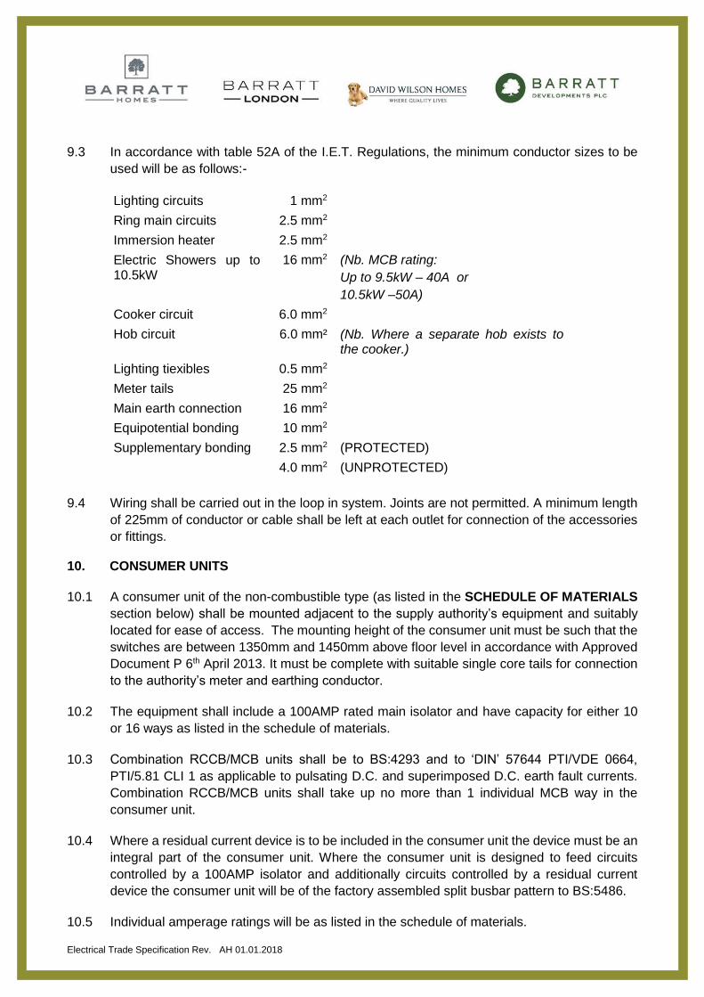
9.3 In accordance with table 52A of the I.E.T. Regulations, the minimum conductor sizes to be
used will be as follows:-
Lighting circuits 1 mm2
Ring main circuits 2.5 mm2
Immersion heater 2.5 mm2
Electric Showers up to 10.5kW
16 mm2 (Nb. MCB rating:
Up to 9.5kW – 40A or
10.5kW –50A)
Cooker circuit 6.0 mm2
Hob circuit 6.0 mm² (Nb. Where a separate hob exists to the cooker.)
Lighting tiexibles 0.5 mm2
Meter tails 25 mm2
Main earth connection 16 mm2
Equipotential bonding 10 mm2
Supplementary bonding 2.5 mm2 (PROTECTED)
4.0 mm2 (UNPROTECTED)
9.4 Wiring shall be carried out in the loop in system. Joints are not permitted. A minimum length
of 225mm of conductor or cable shall be left at each outlet for connection of the accessories
or fittings.
10. CONSUMER UNITS
10.1 A consumer unit of the non-combustible type (as listed in the SCHEDULE OF MATERIALS
section below) shall be mounted adjacent to the supply authority’s equipment and suitably
located for ease of access. The mounting height of the consumer unit must be such that the
switches are between 1350mm and 1450mm above floor level in accordance with Approved
Document P 6th April 2013. It must be complete with suitable single core tails for connection
to the authority’s meter and earthing conductor.
10.2 The equipment shall include a 100AMP rated main isolator and have capacity for either 10
or 16 ways as listed in the schedule of materials.
10.3 Combination RCCB/MCB units shall be to BS:4293 and to ‘DIN’ 57644 PTI/VDE 0664,
PTI/5.81 CLI 1 as applicable to pulsating D.C. and superimposed D.C. earth fault currents.
Combination RCCB/MCB units shall take up no more than 1 individual MCB way in the
consumer unit.
10.4 Where a residual current device is to be included in the consumer unit the device must be an
integral part of the consumer unit. Where the consumer unit is designed to feed circuits
controlled by a 100AMP isolator and additionally circuits controlled by a residual current
device the consumer unit will be of the factory assembled split busbar pattern to BS:5486.
10.5 Individual amperage ratings will be as listed in the schedule of materials.

Electrical Trade Specification Rev. AH 01.01.2018
10.6 Where applicable the RCDs shall hold an ASTA type test certificate.
10.7 Each unit shall be complete and factory assembled with the appropriate number of circuit
ways and earthing terminals for protective conductors including equipotential bonding
conductors. Attention is drawn to Regulations 13-7, 13-16 and 413-2 to 413-17. Permanent
labels shall be affixed to each consumer unit in accordance with Regulations 514-1, 514-3
and 514-5.
10.8 The Contractor is to provide consumer unit installation schedules in accordance with
BS:7671 462-01-02.
10.9 All consumer units are to be fitted with Locking Brackets to allow the units to be locked-off
during the construction phase of the installation. Following which, the hole should be replaced
by a bung to close the hole at handover stage. Refer to the Schedule of Materials for the part
specification for the locking device.
11. DOWNLIGHTERS
11.1 Proprietary acoustic and fire rated downlighters are to be used in order to ensure the acoustic
and fire integrity of the ceiling. The specified Deta products and codes are fully detailed within
the “Schedule of Materials” incorporated within this document.
11.2 Where downlighters are fitted to ceilings with loft space above, the insulator separator (part
of the downlight) allows loft insulation to be laid over the top of the fitting.
11.3 The downlight must be installed in conjunction with Standard Detail no: DB-SD09-003 “Fire
Rated Downlight”, dated October 2014.
11.4 Remote gearboxes and transformers must be situated clear of the insulation, in accordance
with the manufacturers fitting instructions.
12. ELECTRICITY SUPPLIES
12.1 A 230v 50HZ single-phase supply will be provided by the supply authority to each dwelling
terminating at an agreed position. Details of the fault level and the external impedance’s may
be available from the supply authority. If such information is not available the tenderer must
quote the value assumed in his calculation for the fault level. Including the external
impedance, at the origin of each installation.
12.2 In addition the assessed values of earth fault loop impedance shall be quoted in respect of
each circuit and the clearance times as required by I.E.T. Regulations 413-4.
13. EXTERNAL LIGHTS
13.1 For compliance with Part L of the Building regulations that all external light fittings (Security,
bulk head and/or lantern styles), where fitted, must be operated by means of a movement
sensitive PIR photocell that will extinguish when there is sufficient daylight and when not
required at night.
Electrical Trade Specification Rev. AH 01.01.2018
13.2 Where this movement sensitive PIR photocell is not incorporated (integral) within the external
light fitting, then a remote one must be fitted.
14. FINAL CIRCUITS
14.1 Unless otherwise specified, two final circuits shall be installed for socket outlets and one
lighting circuit for each floor. Two-way circuits for staircases shall be associated with lower
floors in each case. Generally, BS 1363 socket outlets shall be installed on ring main final
circuits, and all will be single pole switching.
14.2 Attention is drawn to the requirements for socket outlets, which may be utilised for portable
equipment to be used outside the equipotential zone.
14.3 All sockets in homes must be protected by an RCD in accordance with the latest edition of
the I.E.T. regulations. These also must be single pole switched.
15. MECHANICAL VENTILATION
15.1 All fans are to be of approved type as listed in this Trade Specification under Schedule of Materials.
15.2 Fans can be of either a centrifugal type, recessed, ceiling mounted or, axial type, wall
mounted, where the maximum length of duct to the outside wall is not greater than 1.5m.
15.3 Kitchen (Where no hood extract)
Fans in this location must be capable of giving extraction at a rate not less than 60
litres/second extraction, , ducted to outside through sleeve, duct should be built in brickwork
as work proceeds or 30l/s if the fan is placed over the hob.
15.4 Bathrooms and Ensuites Fans in this location must be capable of giving extraction at a rate not less than 15 litres/sec. Top Floor extract fans are to include a condensation trap if they ducted through an unheated roof space.
Switch to be situated on outside of the Bathroom/En-suite (i.e. on landing or relevant
adjoining room). Where a bathroom or ensuite does not have an openable window, the
extract fan must be light switch operated with a 15 minute overrun.
Were the fan is ducted to a roof tile vent the EnviroVent condensation kit must be used,
flexible ducting to be pulled taught and to be kept to a minimum as per the domestic
ventilation compliance guide.
15.5 Utility
Fans in this location must be capable of giving extraction at a rate not less than 30 litres/sec.
Top Floor extract fans are to include a condensation trap if they ducted through an unheated
roof space.
Were a utility fan is ducted to a roof tile vent the EnviroVent condensation kit must be used,
Electrical Trade Specification Rev. AH 01.01.2018
flexible ducting to be pulled taught and to be kept to a minimum as per the domestic
ventilation compliance guide.
15.6 Internal Cloakroom (Where shown on layout)
Fans in this location must be capable of giving extraction at a rate not less than 6 litres/sec,
wired to light switch, with a 15 minute overrun and ducted to the outside wall and does not
require a condensation trap.
15.7 Ducts and Terminators
The standard specification for ductwork when parallel to ‘I’ joist spans is rigid ductwork all in
accordance with the Group Supplier agreement for mechanical extractors/ductwork.
Aluminium flexible ducting is only to be used for runs going through the joist webs. A rigid
angled boss is to be installed as standard on the back of fans to prevent flexible ducting being
pulled too tightly/squashed and reducing flow rate.
All ducts must be securely fixed to fans ventilation tile, fixed wall grille or air brick.
Where Building Regulations require the protection against fire passage, the use of rigid
ducting is required in accordance with the materials noted in Schedule of Materials provided
by the preferred Group Supplier noted above or where provided in the enquiry
documentation.
Ducting through external walls should be built-in with appropriate sleeve in accordance with the preferred Group Supplier listed above as brickwork/blockwork proceeds.
Extract ducting, must be insulated with minimum 25mm quilt insulation where:
(i) The duct extracts to an extract tile within the Roof Tiling.
(ii) The duct extracts to an eaves position and is positioned on top of the roof
insulation.
15.8 All of the above equipment to be manufactured by Envirovent.
15.9 Condensation Traps A condensation trap is required to be fitted where: -
(i) Insulated ducting is run vertically through an unheated roof space.
A condensation trap is not required if: -
(ii) Insulated ducting is run on top of the insulation and falls to the outside (refer to
BRE Guide - Thermal Insulation - avoiding risks, 2002 edition).
16. PLASTIC CONDUIT
16.1 Plastic Conduit must be installed to protect electrical cables running over the surface of
exposed (non-plaster-boarded) Brick and Block walls, where wiring is indicated on the
working drawings, including, but not limited to, garages.
16.2 This shall be of high impact gauge PVC in accordance with BS 4607 and shall be installed in
accordance with the manufacturer’s recommendations.
Electrical Trade Specification Rev. AH 01.01.2018
17. PROTECTIVE CONDUCTORS
17.1 The latest edition of the I.E.T. Regulations places special significance on the installation of
protective conductors and no deviation from the requirements will be permitted.
17.2 The Contractor will be required to submit documentary evidence to confirm that the
requirements have been complied with to satisfy the shock and thermal constraints, particular
attention is drawn to Regulations 413-3, 413-4 and Appendix 7.
18. SITE CLEANLINESS
18.1 The electrical Contractor shall, at all times, be responsible for ensuring that his areas of work
are maintained in an uncluttered condition.
18.2 All rooms and garages shall be cleaned out upon completion and left free from excess
materials.
18.3 Waste materials are to be removed from site or to an appropriate on-site re-cycling area.
Failure to do so will result in contra-charges being made.
18.4 Upon completion of the contract (or defined sections thereof) the Contractor will clear from
site all stored materials, equipment, site accommodation, etc, no longer required, without
delay.
19. SMOKE DETECTORS
19.1 Smoke detectors must be of the optical type to the ground floor (or first floor if the house type has a first floor kitchen) and of the Ionisation type in all other locations (one at each floor level or as indicated on working drawings), 230v mains supply with 9v battery backup and fully integrated to meet the requirements of the “Smoke Detector Act 1991”, BS 5446 part 1, current Building Regulations (section B1 Means Of Escape)
19.2 Smoke detectors should be wired within the lighting circuit to prevent them from being
disabled separately to other circuits.
20. STATUTORY REQUIREMENTS
20.1 The Contractor shall comply with all statutory regulations of government e.g. Health and
Safety Act, local authority, electrical supply authority, fire prevention office or any other
interested parties.
21. SUPPLY CONNECTION
21.1 Upon agreed completion of an installation the Contractor shall supply the electricity authority
with formal notice of completion and attend the final connection up of the installation.
21.2 Electrical contractors are warned to comply with Regulation 6 13-7, which states that
particular attention shall be given to the presence and shall be isolated so that they are not
damaged by the test voltage.
Electrical Trade Specification Rev. AH 01.01.2018
22. TELEVISION
22.1 The Contractor shall supply and install CT100 Co-Axial cable from the location of the media plate or Co-Axial outlet, as noted in the Sales and Construction Specification, to the roof void with 5m of cable left in a coiled loop to allow future installation of a Television aerial (by the purchaser).
22.2 Where the purchaser has paid for additional locations for Television aerials, these must also be wired with CT100 Co-Axial cable to the roof void.
23. TESTING
23.1 The full requirements of Part 6 and of Appendices 14, 15 and 16 shall be complied with
unless it is agreed that circumstances exist which prevent this, E.G. non-availability of
suitable commercially available testing equipment. Part 2 Clause 11 also refers.
23.2 In accordance with part 6 of the I.E.T. Regulations, including Appendices 14 and 15,
inspection and testing will be carried out to ensure that:
(i) the external impedance and fault level at the origin of the installation do not
obviate the design proposals,
(ii) insulation to earth and between conductors meets requirements,
(iii) earth loop in impedance satisfies the design requirements,
(iv) all single pole switches are in the phase conductors,
(v) equipotential and supplementary bonding conductors are adequately installed
and connected,
(vi) polarity is correct,
(vii) ring main circuits are currently installed,
(viii) residual current circuit breakers operate as required and that the manufacturer’s
instructions are clearly displayed regarding the periodical testing procedures,
(ix) air flow test measurements and checklists for extractor fans need to be carried
out as per the domestic ventilation compliance guide 2010 issued to building
control inspectors.
23.3 The results of all tests shall be recorded and signed using the suggested type of certificate
in accordance with Appendix 16 of the regulations.
23.4 The completion and inspection certificates must be provided to the Company and should be
forwarded to the Surveying Department on completion.
24. WIRE ONLY WORKS
24.1 The Contractor is to include the wiring only of electric showers – to be supplied and installed
by the Plumbing and Heating Contractor.
24.2 The contractor is to include the wiring only of all heating controls – to be supplied by the
Electrical Trade Specification Rev. AH 01.01.2018
Plumbing and Heating Contractor.
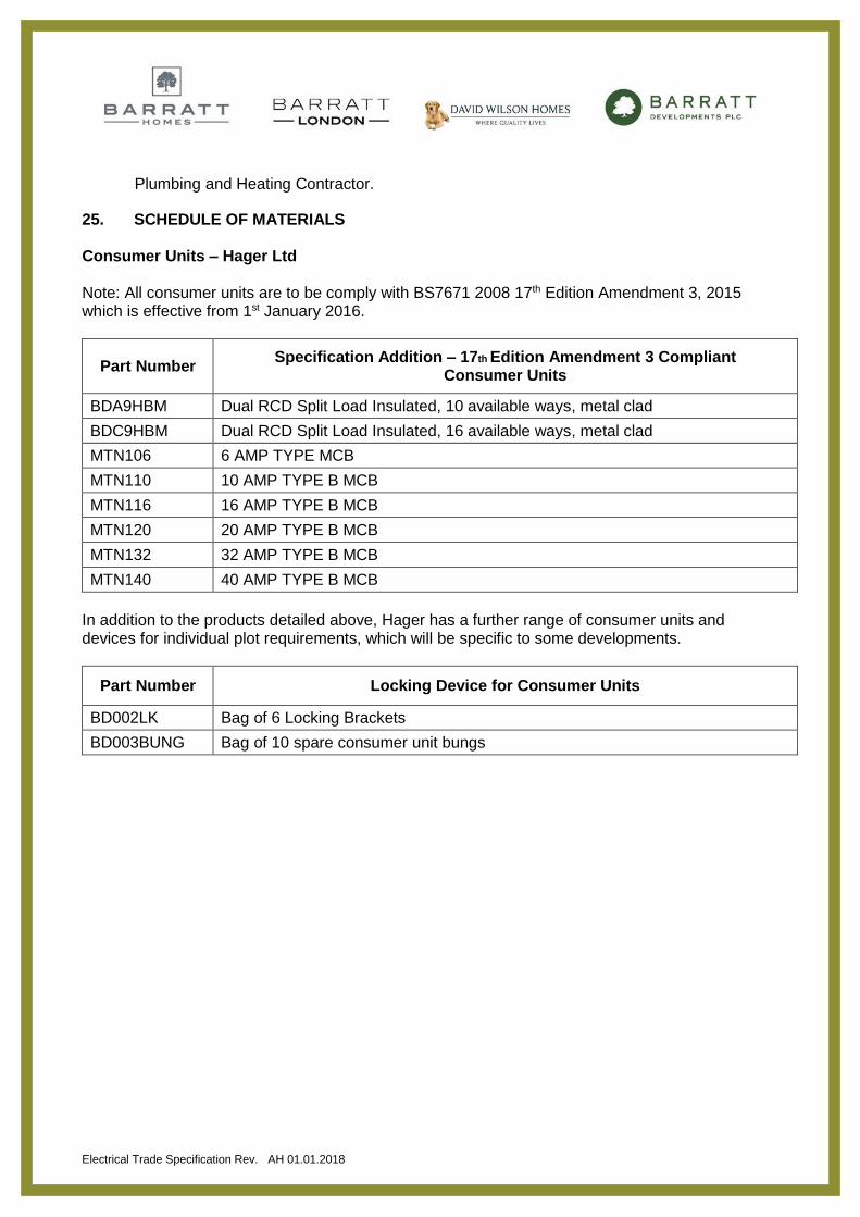
25. SCHEDULE OF MATERIALS Consumer Units – Hager Ltd Note: All consumer units are to be comply with BS7671 2008 17th Edition Amendment 3, 2015 which is effective from 1st January 2016.
Part Number Specification Addition – 17th Edition Amendment 3 Compliant
Consumer Units
BDA9HBM Dual RCD Split Load Insulated, 10 available ways, metal clad
BDC9HBM Dual RCD Split Load Insulated, 16 available ways, metal clad
MTN106 6 AMP TYPE MCB
MTN110 10 AMP TYPE B MCB
MTN116 16 AMP TYPE B MCB
MTN120 20 AMP TYPE B MCB
MTN132 32 AMP TYPE B MCB
MTN140 40 AMP TYPE B MCB
In addition to the products detailed above, Hager has a further range of consumer units and devices for individual plot requirements, which will be specific to some developments.
Part Number Locking Device for Consumer Units
BD002LK Bag of 6 Locking Brackets
BD003BUNG Bag of 10 spare consumer unit bungs
Electrical Trade Specification Rev. AH 01.01.2018
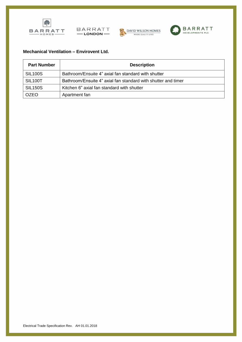
Mechanical Ventilation – Envirovent Ltd.
Part Number Description
SIL100S Bathroom/Ensuite 4” axial fan standard with shutter
SIL100T Bathroom/Ensuite 4” axial fan standard with shutter and timer
SIL150S Kitchen 6” axial fan standard with shutter
OZEO Apartment fan
Electrical Trade Specification Rev. AH 01.01.2018
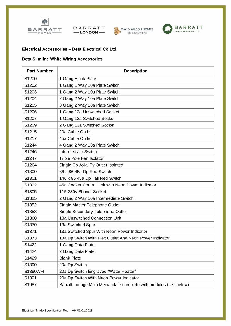
Electrical Accessories – Deta Electrical Co Ltd Deta Slimline White Wiring Accessories
Part Number Description
S1200 1 Gang Blank Plate
S1202 1 Gang 1 Way 10a Plate Switch
S1203 1 Gang 2 Way 10a Plate Switch
S1204 2 Gang 2 Way 10a Plate Switch
S1205 3 Gang 2 Way 10a Plate Switch
S1206 1 Gang 13a Unswitched Socket
S1207 1 Gang 13a Switched Socket
S1209 2 Gang 13a Switched Socket
S1215 20a Cable Outlet
S1217 45a Cable Outlet
S1244 4 Gang 2 Way 10a Plate Switch
S1246 Intermediate Switch
S1247 Triple Pole Fan Isolator
S1264 Single Co-Axial Tv Outlet Isolated
S1300 86 x 86 45a Dp Red Switch
S1301 146 x 86 45a Dp Tall Red Switch
S1302 45a Cooker Control Unit with Neon Power Indicator
S1305 115-230v Shaver Socket
S1325 2 Gang 2 Way 10a Intermediate Switch
S1352 Single Master Telephone Outlet
S1353 Single Secondary Telephone Outlet
S1360 13a Unswitched Connection Unit
S1370 13a Switched Spur
S1371 13a Switched Spur With Neon Power Indicator
S1373 13a Dp Switch With Flex Outlet And Neon Power Indicator
S1422 1 Gang Data Plate
S1424 2 Gang Data Plate
S1429 Blank Plate
S1390 20a Dp Switch
S1390WH 20a Dp Switch Engraved “Water Heater”
S1391 20a Dp Switch With Neon Power Indicator
S1987 Barratt Lounge Multi Media plate complete with modules (see below)
Electrical Trade Specification Rev. AH 01.01.2018
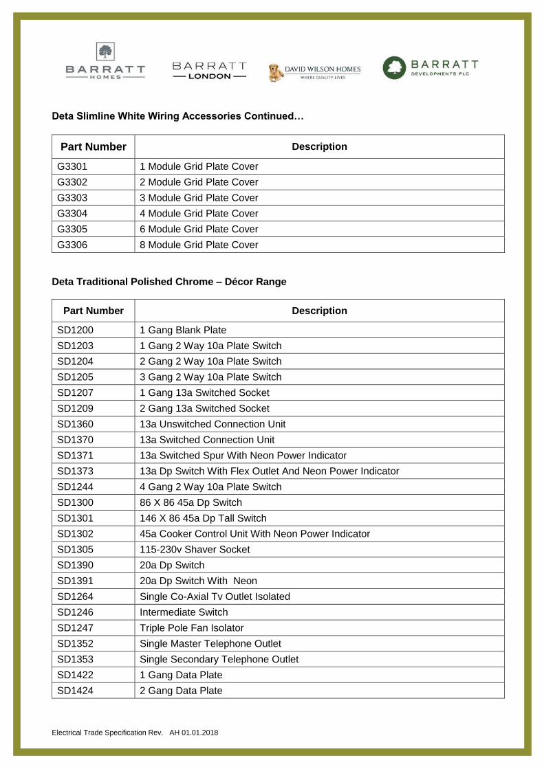
Deta Slimline White Wiring Accessories Continued…
Part Number Description
G3301 1 Module Grid Plate Cover
G3302 2 Module Grid Plate Cover
G3303 3 Module Grid Plate Cover
G3304 4 Module Grid Plate Cover
G3305 6 Module Grid Plate Cover
G3306 8 Module Grid Plate Cover
Deta Traditional Polished Chrome – Décor Range
Part Number Description
SD1200 1 Gang Blank Plate
SD1203 1 Gang 2 Way 10a Plate Switch
SD1204 2 Gang 2 Way 10a Plate Switch
SD1205 3 Gang 2 Way 10a Plate Switch
SD1207 1 Gang 13a Switched Socket
SD1209 2 Gang 13a Switched Socket
SD1360 13a Unswitched Connection Unit
SD1370 13a Switched Connection Unit
SD1371 13a Switched Spur With Neon Power Indicator
SD1373 13a Dp Switch With Flex Outlet And Neon Power Indicator
SD1244 4 Gang 2 Way 10a Plate Switch
SD1300 86 X 86 45a Dp Switch
SD1301 146 X 86 45a Dp Tall Switch
SD1302 45a Cooker Control Unit With Neon Power Indicator
SD1305 115-230v Shaver Socket
SD1390 20a Dp Switch
SD1391 20a Dp Switch With Neon
SD1264 Single Co-Axial Tv Outlet Isolated
SD1246 Intermediate Switch
SD1247 Triple Pole Fan Isolator
SD1352 Single Master Telephone Outlet
SD1353 Single Secondary Telephone Outlet
SD1422 1 Gang Data Plate
SD1424 2 Gang Data Plate
Electrical Trade Specification Rev. AH 01.01.2018
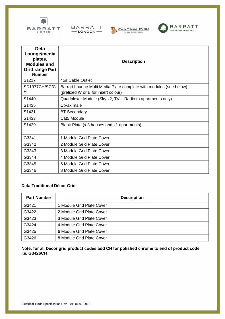
Deta Lounge/media
plates, Modules and
Grid range Part Number
Description
S1217 45a Cable Outlet
SD1977CH/SC/CH
Barratt Lounge Multi Media Plate complete with modules (see below)
(prefixed W or B for insert colour)
S1440 Quadplexer Module (Sky x2, TV + Radio to apartments only)
S1435 Co-ax male
S1431 BT Secondary
S1433 Cat5 Module
S1429 Blank Plate (x 3 houses and x1 apartments)
G3341 1 Module Grid Plate Cover
G3342 2 Module Grid Plate Cover
G3343 3 Module Grid Plate Cover
G3344 4 Module Grid Plate Cover
G3345 6 Module Grid Plate Cover
G3346 8 Module Grid Plate Cover
Deta Traditional Décor Grid
Part Number Description
G3421 1 Module Grid Plate Cover
G3422 2 Module Grid Plate Cover
G3423 3 Module Grid Plate Cover
G3424 4 Module Grid Plate Cover
G3425 6 Module Grid Plate Cover
G3426 8 Module Grid Plate Cover
Note: for all Décor grid product codes add CH for polished chrome to end of product code i.e. G3426CH
Electrical Trade Specification Rev. AH 01.01.2018
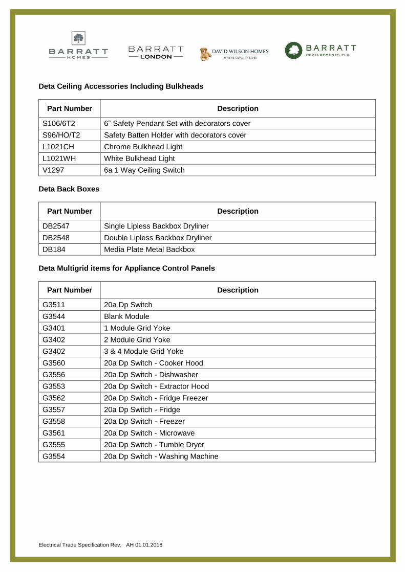
Deta Ceiling Accessories Including Bulkheads
Part Number Description
S106/6T2 6” Safety Pendant Set with decorators cover
S96/HO/T2 Safety Batten Holder with decorators cover
L1021CH Chrome Bulkhead Light
L1021WH White Bulkhead Light
V1297 6a 1 Way Ceiling Switch
Deta Back Boxes
Part Number Description
DB2547 Single Lipless Backbox Dryliner
DB2548 Double Lipless Backbox Dryliner
DB184 Media Plate Metal Backbox
Deta Multigrid items for Appliance Control Panels
Part Number Description
G3511 20a Dp Switch
G3544 Blank Module
G3401 1 Module Grid Yoke
G3402 2 Module Grid Yoke
G3402 3 & 4 Module Grid Yoke
G3560 20a Dp Switch - Cooker Hood
G3556 20a Dp Switch - Dishwasher
G3553 20a Dp Switch - Extractor Hood
G3562 20a Dp Switch - Fridge Freezer
G3557 20a Dp Switch - Fridge
G3558 20a Dp Switch - Freezer
G3561 20a Dp Switch - Microwave
G3555 20a Dp Switch - Tumble Dryer
G3554 20a Dp Switch - Washing Machine
Electrical Trade Specification Rev. AH 01.01.2018
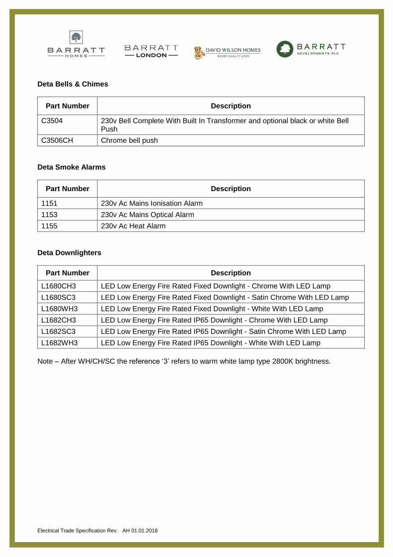
Deta Bells & Chimes
Part Number Description
C3504 230v Bell Complete With Built In Transformer and optional black or white Bell Push
C3506CH Chrome bell push
Deta Smoke Alarms
Part Number Description
1151 230v Ac Mains Ionisation Alarm
1153 230v Ac Mains Optical Alarm
1155 230v Ac Heat Alarm
Deta Downlighters
Part Number Description
L1680CH3 LED Low Energy Fire Rated Fixed Downlight - Chrome With LED Lamp
L1680SC3 LED Low Energy Fire Rated Fixed Downlight - Satin Chrome With LED Lamp
L1680WH3 LED Low Energy Fire Rated Fixed Downlight - White With LED Lamp
L1682CH3 LED Low Energy Fire Rated IP65 Downlight - Chrome With LED Lamp
L1682SC3 LED Low Energy Fire Rated IP65 Downlight - Satin Chrome With LED Lamp
L1682WH3 LED Low Energy Fire Rated IP65 Downlight - White With LED Lamp
Note – After WH/CH/SC the reference ‘3’ refers to warm white lamp type 2800K brightness.
Electrical Trade Specification Rev. AH 01.01.2018
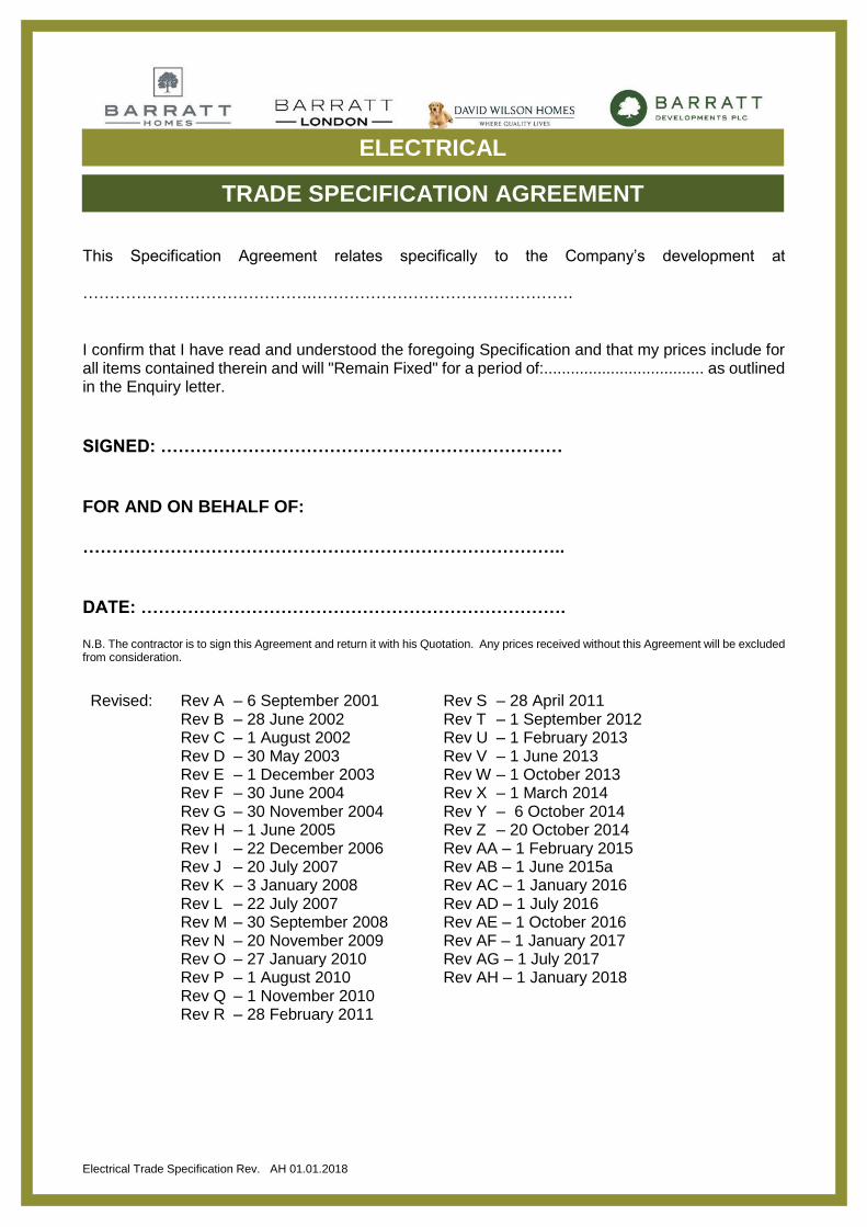
This Specification Agreement relates specifically to the Company’s development at
…………………………………….………………………………………….
I confirm that I have read and understood the foregoing Specification and that my prices include for all items contained therein and will "Remain Fixed" for a period of:.................................... as outlined in the Enquiry letter.
SIGNED: …………………………………………………………… FOR AND ON BEHALF OF: ……………………………………………………………………….. DATE: ………………………………………………………………. N.B. The contractor is to sign this Agreement and return it with his Quotation. Any prices received without this Agreement will be excluded from consideration.
Revised: Rev A – 6 September 2001 Rev S – 28 April 2011
Rev B – 28 June 2002 Rev T – 1 September 2012 Rev C – 1 August 2002 Rev U – 1 February 2013 Rev D – 30 May 2003 Rev V – 1 June 2013 Rev E – 1 December 2003 Rev W – 1 October 2013 Rev F – 30 June 2004 Rev X – 1 March 2014 Rev G – 30 November 2004 Rev Y – 6 October 2014 Rev H – 1 June 2005 Rev Z – 20 October 2014 Rev I – 22 December 2006 Rev AA – 1 February 2015 Rev J – 20 July 2007 Rev AB – 1 June 2015a Rev K – 3 January 2008 Rev AC – 1 January 2016 Rev L – 22 July 2007 Rev AD – 1 July 2016 Rev M – 30 September 2008 Rev AE – 1 October 2016 Rev N – 20 November 2009 Rev AF – 1 January 2017 Rev O – 27 January 2010 Rev AG – 1 July 2017 Rev P – 1 August 2010 Rev Q – 1 November 2010 Rev R – 28 February 2011
Rev AH – 1 January 2018
ELECTRICAL
TRADE SPECIFICATION AGREEMENT