Embed Size (px)
Citation preview
16
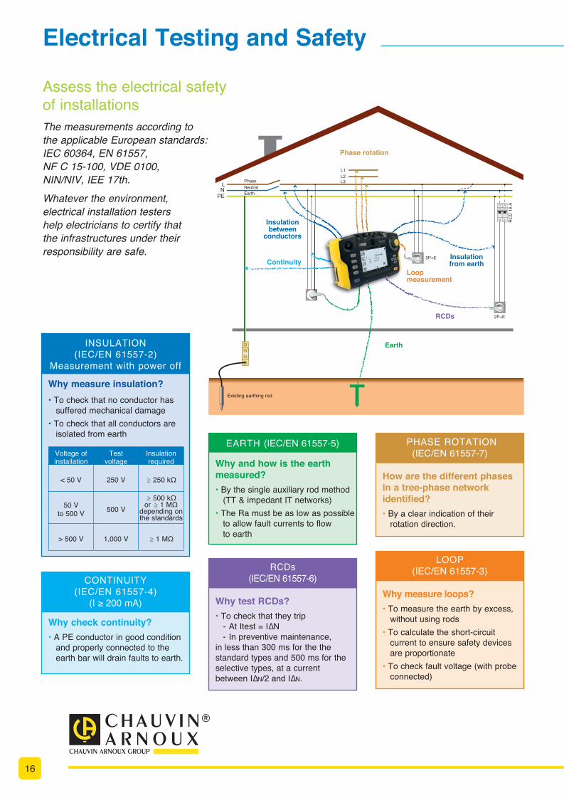
Assess the electrical safety of installationsThe measurements according to the applicable European standards: IEC 60364, EN 61557, NF C 15-100, VDE 0100, NIN/NIV, IEE 17th.Whatever the environment, electrical installation testers help electricians to certify that the infrastructures under their responsibility are safe.
Electrical Testing and Safety
Phase rotation
ContinuityLoopmeasurement
Earth
RCDs
Insulationbetween
conductors
Insulationfrom earth
LN
PE
Phase
EarthNeutral
L1
L3L2
RC
D 1
6 A
2P+E
2P+E
Existing earthing rod
CONTINUITY(IEC/EN 61557-4)
(I ≥ 200 mA)
Why check continuity?• A PE conductor in good condition and properly connected to the earth bar will drain faults to earth.
PHASE ROTATION(IEC/EN 61557-7)
How are the different phases in a tree-phase network identified?• By a clear indication of their rotation direction.
LOOP (IEC/EN 61557-3)
Why measure loops?• To measure the earth by excess, without using rods• To calculate the short-circuit current to ensure safety devices are proportionate• To check fault voltage (with probe connected)
EARTH (IEC/EN 61557-5)
Why and how is the earth measured? • By the single auxiliary rod method (TT & impedant IT networks)• The Ra must be as low as possible to allow fault currents to flow to earth
INSULATION(IEC/EN 61557-2)
Measurement with power off
Why measure insulation?• To check that no conductor has suffered mechanical damage• To check that all conductors are isolated from earth
Voltage of installation
Test voltage
Insulation required
< 50 V 250 V ≥ 250 kΩ
50 V to 500 V 500 V
≥ 500 kΩ or ≥ 1 MΩ
depending on the standards
> 500 V 1,000 V ≥ 1 MΩ
RCDs (IEC/EN 61557-6)
Why test RCDs?• To check that they trip - At Itest = I∆N - In preventive maintenance, in less than 300 ms for the the standard types and 500 ms for the selective types, at a current between I∆N/2 and I∆N.
17
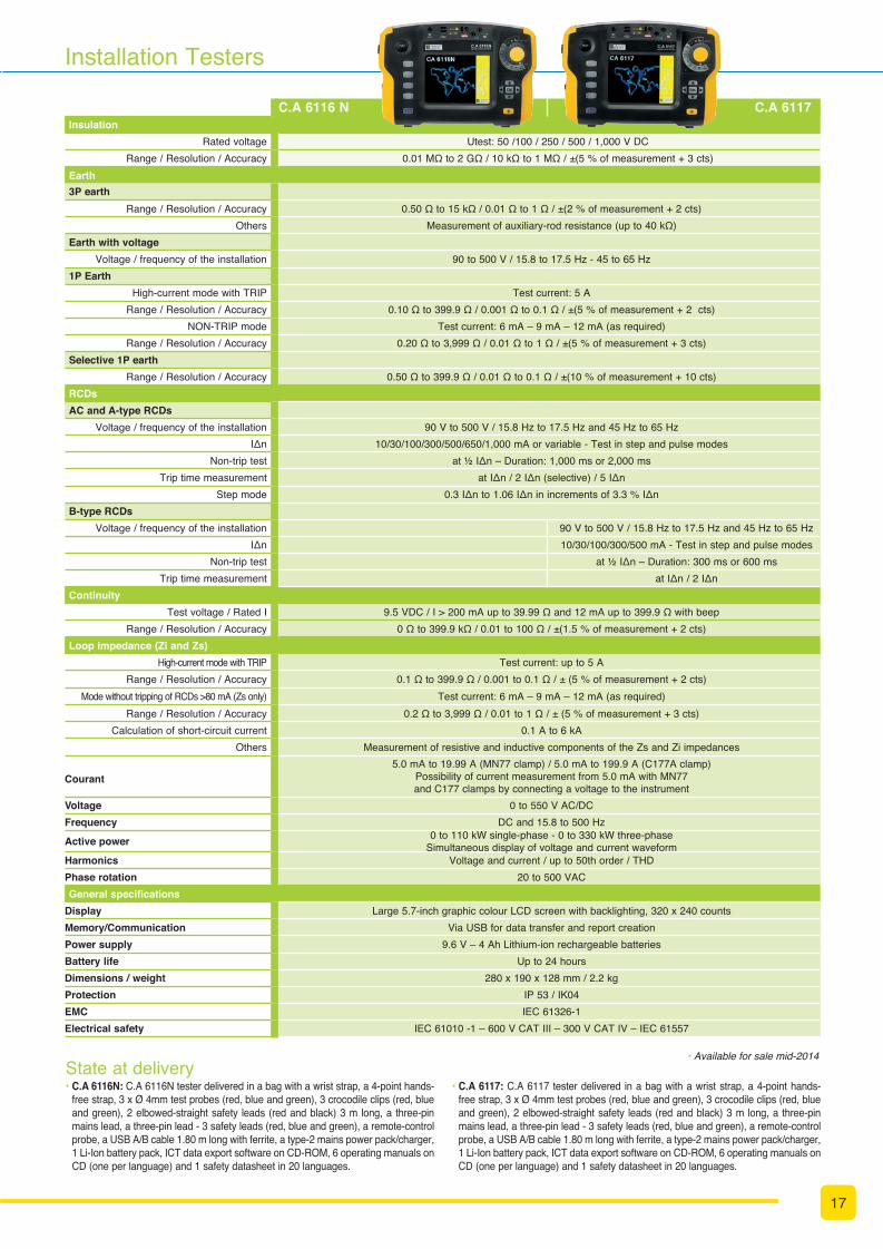
Installation Testers
C.A 6116 N C.A 6117Insulation
Rated voltage Utest: 50 /100 / 250 / 500 / 1,000 V DC Range / Resolution / Accuracy 0.01 MΩ to 2 GΩ / 10 kΩ to 1 MΩ / ±(5 % of measurement + 3 cts)
Earth3P earth
Range / Resolution / Accuracy 0.50 Ω to 15 kΩ / 0.01 Ω to 1 Ω / ±(2 % of measurement + 2 cts) Others Measurement of auxiliary-rod resistance (up to 40 kΩ)
Earth with voltageVoltage / frequency of the installation 90 to 500 V / 15.8 to 17.5 Hz - 45 to 65 Hz
1P EarthHigh-current mode with TRIP Test current: 5 A
Range / Resolution / Accuracy 0.10 Ω to 399.9 Ω / 0.001 Ω to 0.1 Ω / ±(5 % of measurement + 2 cts) NON-TRIP mode Test current: 6 mA – 9 mA – 12 mA (as required)
Range / Resolution / Accuracy 0.20 Ω to 3,999 Ω / 0.01 Ω to 1 Ω / ±(5 % of measurement + 3 cts) Selective 1P earth
Range / Resolution / Accuracy 0.50 Ω to 399.9 Ω / 0.01 Ω to 0.1 Ω / ±(10 % of measurement + 10 cts) RCDsAC and A-type RCDs
Voltage / frequency of the installation 90 V to 500 V / 15.8 Hz to 17.5 Hz and 45 Hz to 65 Hz IΔn 10/30/100/300/500/650/1,000 mA or variable - Test in step and pulse modes
Non-trip test at ½ IΔn – Duration: 1,000 ms or 2,000 ms Trip time measurement at IΔn / 2 IΔn (selective) / 5 IΔn
Step mode 0.3 IΔn to 1.06 IΔn in increments of 3.3 % IΔn B-type RCDs
Voltage / frequency of the installation 90 V to 500 V / 15.8 Hz to 17.5 Hz and 45 Hz to 65 Hz IΔn 10/30/100/300/500 mA - Test in step and pulse modes
Non-trip test at ½ IΔn – Duration: 300 ms or 600 ms Trip time measurement at IΔn / 2 IΔn
ContinuityTest voltage / Rated I 9.5 VDC / I > 200 mA up to 39.99 Ω and 12 mA up to 399.9 Ω with beep
Range / Resolution / Accuracy 0 Ω to 399.9 kΩ / 0.01 to 100 Ω / ±(1.5 % of measurement + 2 cts) Loop impedance (Zi and Zs)
High-current mode with TRIP Test current: up to 5 A Range / Resolution / Accuracy 0.1 Ω to 399.9 Ω / 0.001 to 0.1 Ω / ± (5 % of measurement + 2 cts)
Mode without tripping of RCDs >80 mA (Zs only) Test current: 6 mA – 9 mA – 12 mA (as required) Range / Resolution / Accuracy 0.2 Ω to 3,999 Ω / 0.01 to 1 Ω / ± (5 % of measurement + 3 cts)
Calculation of short-circuit current 0.1 A to 6 kA Others Measurement of resistive and inductive components of the Zs and Zi impedances
Courant 5.0 mA to 19.99 A (MN77 clamp) / 5.0 mA to 199.9 A (C177A clamp)
Possibility of current measurement from 5.0 mA with MN77 and C177 clamps by connecting a voltage to the instrument
Voltage 0 to 550 V AC/DC Frequency DC and 15.8 to 500 Hz
Active power 0 to 110 kW single-phase - 0 to 330 kW three-phaseSimultaneous display of voltage and current waveform
Harmonics Voltage and current / up to 50th order / THD Phase rotation 20 to 500 VAC General specifications
Display Large 5.7-inch graphic colour LCD screen with backlighting, 320 x 240 counts Memory/Communication Via USB for data transfer and report creationPower supply 9.6 V – 4 Ah Lithium-ion rechargeable batteriesBattery life Up to 24 hoursDimensions / weight 280 x 190 x 128 mm / 2.2 kg Protection IP 53 / IK04 EMC IEC 61326-1 Electrical safety IEC 61010 -1 – 600 V CAT III – 300 V CAT IV – IEC 61557
• Available for sale mid-2014 State at delivery• C.A 6116N: C.A 6116N tester delivered in a bag with a wrist strap, a 4-point hands-
free strap, 3 x Ø 4mm test probes (red, blue and green), 3 crocodile clips (red, blue and green), 2 elbowed-straight safety leads (red and black) 3 m long, a three-pin mains lead, a three-pin lead - 3 safety leads (red, blue and green), a remote-control probe, a USB A/B cable 1.80 m long with ferrite, a type-2 mains power pack/charger, 1 Li-Ion battery pack, ICT data export software on CD-ROM, 6 operating manuals on CD (one per language) and 1 safety datasheet in 20 languages.
• C.A 6117: C.A 6117 tester delivered in a bag with a wrist strap, a 4-point hands-free strap, 3 x Ø 4mm test probes (red, blue and green), 3 crocodile clips (red, blue and green), 2 elbowed-straight safety leads (red and black) 3 m long, a three-pin mains lead, a three-pin lead - 3 safety leads (red, blue and green), a remote-control probe, a USB A/B cable 1.80 m long with ferrite, a type-2 mains power pack/charger, 1 Li-Ion battery pack, ICT data export software on CD-ROM, 6 operating manuals on CD (one per language) and 1 safety datasheet in 20 languages.


![AUTOMATIKA - c-develop4]_Reyneke... · AUTOMATIKA . Journal for Control, Measurement, Electronics, Computing and Communications . Online ISSN 1848-3380, Print ISSN 0005-1144, doi:](https://img.pdfslide.us/doc/110x75/5e31bc3bd3916a4c7866752f/automatika-c-develop-4reyneke-automatika-journal-for-control-measurement.jpg)