Embed Size (px)
Citation preview
Developed by Truman C. Surbrook, Ph.D., P.E., Master Electrician and Professor, and Jonathan R. Althouse, Master1
Electrician and Instructor, Agricultural Engineering Department, Michigan State University, East Lansing, MI 48824-1323. For acopy of this Tech Note and other educational papers, visit the Electrical Technology web site at http://www.egr.msu.edu/age/
MSU is an affirmative-action, equal-opportunity institution.
Electrical Tech Note — 103Agricultural Engineering Department
Michigan State University
Understanding Electric Motor Nameplates1
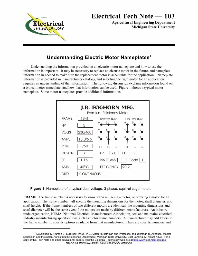
Understanding the information provided on an electric motor nameplate and how to use theinformation is important. It may be necessary to replace an electric motor in the future, and nameplateinformation in needed to make sure the replacement motor is acceptable for the application. Nameplateinformation is provided in manufacturers catalogs, and selecting the right motor for an applicationrequires an understanding of that information. The following discussion explains information found ona typical motor nameplate, and how that information can be used. Figure 1 shows a typical motornameplate. Some motor nameplates provide additional information.
Figure 1 Nameplate of a typical dual-voltage, 3-phase, squirrel cage motor.
FRAME The frame number is necessary to know when replacing a motor, or ordering a motor for anapplication. The frame number will specify the mounting dimensions for the motor, shaft diameter, andshaft height. If the frame numbers of two different motors are identical, the mounting dimensions andshaft diameter will be the same even if the motors are made by different manufacturers. An industrytrade organization, NEMA, National Electrical Manufacturers Association, sets and maintains electricalindustry manufacturing specifications such as motor frame numbers. A manufacturer may add letters tothe frame number to specify options available from that manufacturer. There are specific numbers and
Electrical Tech Note — 103 Page 2
letters which have the same meaning regardless of which manufacturer builds the motor. There aremotors built for specific purposes that have unique frame numbers. This discussion deals with generalpurpose motors.
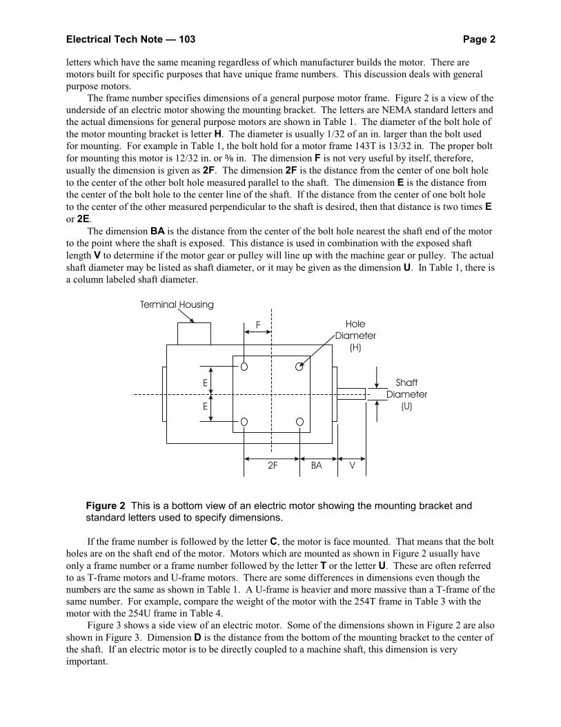
The frame number specifies dimensions of a general purpose motor frame. Figure 2 is a view of theunderside of an electric motor showing the mounting bracket. The letters are NEMA standard letters andthe actual dimensions for general purpose motors are shown in Table 1. The diameter of the bolt hole ofthe motor mounting bracket is letter H. The diameter is usually 1/32 of an in. larger than the bolt usedfor mounting. For example in Table 1, the bolt hold for a motor frame 143T is 13/32 in. The proper boltfor mounting this motor is 12/32 in. or d in. The dimension F is not very useful by itself, therefore,usually the dimension is given as 2F. The dimension 2F is the distance from the center of one bolt holeto the center of the other bolt hole measured parallel to the shaft. The dimension E is the distance fromthe center of the bolt hole to the center line of the shaft. If the distance from the center of one bolt holeto the center of the other measured perpendicular to the shaft is desired, then that distance is two times Eor 2E.
The dimension BA is the distance from the center of the bolt hole nearest the shaft end of the motorto the point where the shaft is exposed. This distance is used in combination with the exposed shaftlength V to determine if the motor gear or pulley will line up with the machine gear or pulley. The actualshaft diameter may be listed as shaft diameter, or it may be given as the dimension U. In Table 1, there isa column labeled shaft diameter.
Figure 2 This is a bottom view of an electric motor showing the mounting bracket andstandard letters used to specify dimensions.
If the frame number is followed by the letter C, the motor is face mounted. That means that the boltholes are on the shaft end of the motor. Motors which are mounted as shown in Figure 2 usually haveonly a frame number or a frame number followed by the letter T or the letter U. These are often referredto as T-frame motors and U-frame motors. There are some differences in dimensions even though thenumbers are the same as shown in Table 1. A U-frame is heavier and more massive than a T-frame of thesame number. For example, compare the weight of the motor with the 254T frame in Table 3 with themotor with the 254U frame in Table 4.
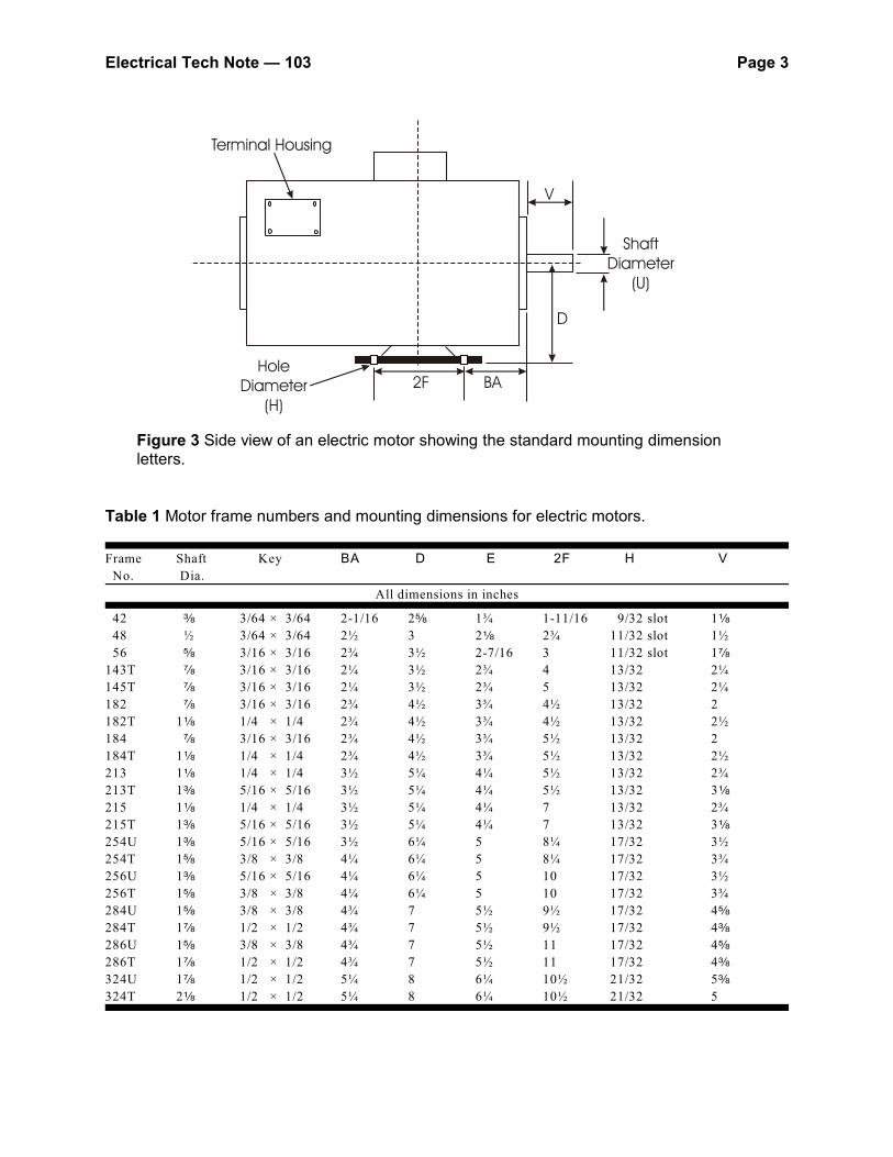
Figure 3 shows a side view of an electric motor. Some of the dimensions shown in Figure 2 are alsoshown in Figure 3. Dimension D is the distance from the bottom of the mounting bracket to the center ofthe shaft. If an electric motor is to be directly coupled to a machine shaft, this dimension is veryimportant.
Electrical Tech Note — 103 Page 3
Figure 3 Side view of an electric motor showing the standard mounting dimensionletters.
Table 1 Motor frame numbers and mounting dimensions for electric motors.
Frame Shaft Key BA D E 2F H V
No. Dia.
All dimensions in inches
42 d 3/64 × 3/64 2-1/16 2e 1¾ 1-11/16 9/32 slot 1c
48 ½ 3/64 × 3/64 2½ 3 2c 2¾ 11/32 slot 1½
56 e 3/16 × 3/16 2¾ 3½ 2-7/16 3 11/32 slot 1f
143T f 3/16 × 3/16 2¼ 3½ 2¾ 4 13/32 2¼
145T f 3/16 × 3/16 2¼ 3½ 2¾ 5 13/32 2¼
182 f 3/16 × 3/16 2¾ 4½ 3¾ 4½ 13/32 2
182T 1c 1/4 × 1/4 2¾ 4½ 3¾ 4½ 13/32 2½
184 f 3/16 × 3/16 2¾ 4½ 3¾ 5½ 13/32 2
184T 1c 1/4 × 1/4 2¾ 4½ 3¾ 5½ 13/32 2½
213 1c 1/4 × 1/4 3½ 5¼ 4¼ 5½ 13/32 2¾
213T 1d 5/16 × 5/16 3½ 5¼ 4¼ 5½ 13/32 3c
215 1c 1/4 × 1/4 3½ 5¼ 4¼ 7 13/32 2¾
215T 1d 5/16 × 5/16 3½ 5¼ 4¼ 7 13/32 3c
254U 1d 5/16 × 5/16 3½ 6¼ 5 8¼ 17/32 3½
254T 1e 3/8 × 3/8 4¼ 6¼ 5 8¼ 17/32 3¾
256U 1d 5/16 × 5/16 4¼ 6¼ 5 10 17/32 3½
256T 1e 3/8 × 3/8 4¼ 6¼ 5 10 17/32 3¾
284U 1e 3/8 × 3/8 4¾ 7 5½ 9½ 17/32 4e
284T 1f 1/2 × 1/2 4¾ 7 5½ 9½ 17/32 4d
286U 1e 3/8 × 3/8 4¾ 7 5½ 11 17/32 4e
286T 1f 1/2 × 1/2 4¾ 7 5½ 11 17/32 4d
324U 1f 1/2 × 1/2 5¼ 8 6¼ 10½ 21/32 5d
324T 2c 1/2 × 1/2 5¼ 8 6¼ 10½ 21/32 5
Electrical Tech Note — 103 Page 4
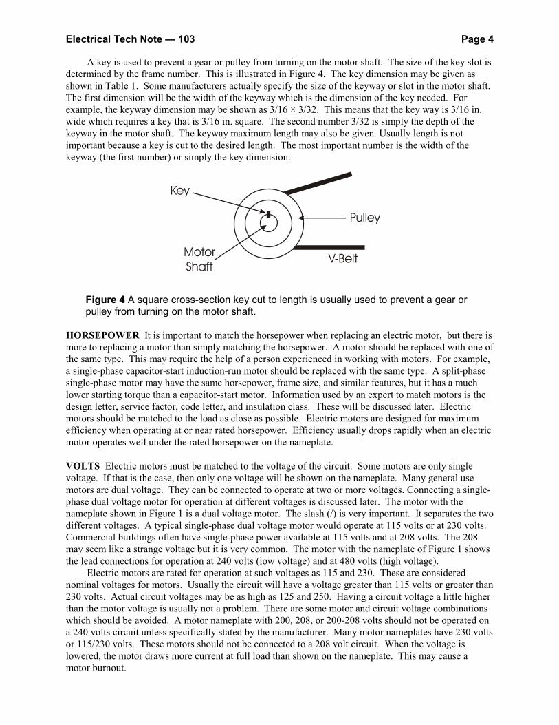
A key is used to prevent a gear or pulley from turning on the motor shaft. The size of the key slot isdetermined by the frame number. This is illustrated in Figure 4. The key dimension may be given asshown in Table 1. Some manufacturers actually specify the size of the keyway or slot in the motor shaft. The first dimension will be the width of the keyway which is the dimension of the key needed. Forexample, the keyway dimension may be shown as 3/16 × 3/32. This means that the key way is 3/16 in.wide which requires a key that is 3/16 in. square. The second number 3/32 is simply the depth of thekeyway in the motor shaft. The keyway maximum length may also be given. Usually length is notimportant because a key is cut to the desired length. The most important number is the width of thekeyway (the first number) or simply the key dimension.
Figure 4 A square cross-section key cut to length is usually used to prevent a gear orpulley from turning on the motor shaft.
HORSEPOWER It is important to match the horsepower when replacing an electric motor, but there ismore to replacing a motor than simply matching the horsepower. A motor should be replaced with one ofthe same type. This may require the help of a person experienced in working with motors. For example,a single-phase capacitor-start induction-run motor should be replaced with the same type. A split-phasesingle-phase motor may have the same horsepower, frame size, and similar features, but it has a muchlower starting torque than a capacitor-start motor. Information used by an expert to match motors is thedesign letter, service factor, code letter, and insulation class. These will be discussed later. Electricmotors should be matched to the load as close as possible. Electric motors are designed for maximumefficiency when operating at or near rated horsepower. Efficiency usually drops rapidly when an electricmotor operates well under the rated horsepower on the nameplate.
VOLTS Electric motors must be matched to the voltage of the circuit. Some motors are only singlevoltage. If that is the case, then only one voltage will be shown on the nameplate. Many general usemotors are dual voltage. They can be connected to operate at two or more voltages. Connecting a single-phase dual voltage motor for operation at different voltages is discussed later. The motor with thenameplate shown in Figure 1 is a dual voltage motor. The slash (/) is very important. It separates the twodifferent voltages. A typical single-phase dual voltage motor would operate at 115 volts or at 230 volts. Commercial buildings often have single-phase power available at 115 volts and at 208 volts. The 208may seem like a strange voltage but it is very common. The motor with the nameplate of Figure 1 showsthe lead connections for operation at 240 volts (low voltage) and at 480 volts (high voltage).
Electric motors are rated for operation at such voltages as 115 and 230. These are considerednominal voltages for motors. Usually the circuit will have a voltage greater than 115 volts or greater than230 volts. Actual circuit voltages may be as high as 125 and 250. Having a circuit voltage a little higherthan the motor voltage is usually not a problem. There are some motor and circuit voltage combinationswhich should be avoided. A motor nameplate with 200, 208, or 200-208 volts should not be operated ona 240 volts circuit unless specifically stated by the manufacturer. Many motor nameplates have 230 voltsor 115/230 volts. These motors should not be connected to a 208 volt circuit. When the voltage islowered, the motor draws more current at full load than shown on the nameplate. This may cause amotor burnout.
Electrical Tech Note — 103 Page 5
AMPS The amperes shown on the motor nameplate are the full-load amperes drawn by the motor at thevoltages given. First consider a motor with a nameplate marked 115/230 volts and 6.2/3.1 amps. Thenameplate is saying that when the motor is operating at 115 volts and at full-load, the motor will draw 6.2amperes. If the motor is rewired to operate at 230 volts, it will have a full-load current of 3.1 amperes.
It takes both volts and amperes to get horsepower form a motor. If the volts are doubled from 115to 230, it will take only half as much current at 230 volts as at 115 volts. This is why it is usuallyrecommended that motors be operated at the highest voltage for which the motor is rated. If the motordraws less current by being operated at 230 volts rather than 115 volts, the supply wire will not need tobe as large. Also, there will be less voltage drop on the line. Motors in particular can be damaged if theyare operated with an excessive amount of voltage drop. If the previous motor draws 6.2 amperes todeliver the rated horsepower of the motor at 115 volts, it will have to draw even more current to deliverthe same horsepower if the power reaching the motor is only 100 volts. If the motor overload protectorsare properly sized, the motor will shut down due to a current overload before the current overheats themotor. If the motor is not properly protected from overload, it will be damaged due to excessive heat. Refer to the motor with the nameplate shown in Figure 1. That motor draws 13.0 amperes at 230 volts. If the same motor was operated from a 480 volt 3-phase supply the motor would only draw 6.5 amperes.
The manufacturer marks on the nameplate the full-load current of the motor which is used whendetermining the size of overload sensing elements for the motor circuit. The National Electrical Code
®
contains a Table 430.150 that given the values of motor full-load current for a 3-phase motor that isrequired to be used to size components in the circuit other than the running overcurrent protection. In thecase of a single-phase motor, the full-load current is given in Table 430.148.
R.P.M. Typical motors for general use are induction motors. Induction motors have a variation in full-load operating speed depending upon how they are designed. Machines and equipment usually are notrequired to operate at an exact speed. It usually does not matter if one motor has an RPM which isslightly different form another motor. For an induction motor, the RPM will change as the load on themotor changes. If the load on a motor increases, the RPM will decrease. If the load gets too heavy, themotor will stall. As the load on an induction motor is decreased, the RPM will increase, but there is amaximum limit.
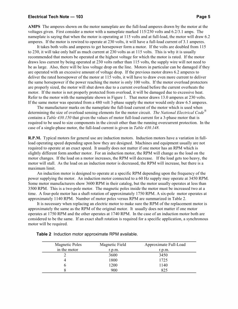
An induction motor is designed to operate at a specific RPM depending upon the frequency of the power supplying the motor. An induction motor connected to a 60 Hz supply may operate at 3450 RPM. Some motor manufacturers show 3600 RPM in their catalog, but the motor usually operates at less than3500 RPM. This is a two-pole motor. The magnetic poles inside the motor must be increased two at atime. A four-pole motor has a shaft rotation of approximately 1750 RPM. A six-pole motor operates atapproximately 1140 RPM. Number of motor poles versus RPM are summarized in Table 2.
It is necessary when replacing an electric motor to make sure the RPM of the replacement motor isapproximately the same as the RPM of the original motor. It usually does not matter if one motoroperates at 1750 RPM and the other operates at 1740 RPM. In the case of an induction motor both areconsidered to be the same. If an exact shaft rotation is required for a specific application, a synchronousmotor will be required.
Table 2 Induction motor approximate RPM available.
Magnetic Poles Magnetic Field Approximate Full-Load in the motor r.p.m. r.p.m.
2 3600 34504 1800 17256 1200 11408 900 825
Electrical Tech Note — 103 Page 6
HERTZ The designation Hz on the motor nameplate refers to the frequency of the electrical powersupplying the motor. In the United States, electrical power is produced and distributed at 60 cycles persecond which is given the units of hertz. Hertz stands for cycles per second. Some power systems in theworld operate at 50 hertz. When replacing a motor, make sure the motor is rated to operate at 60 hertz. A motor designed for 50 hertz when powered by a 60 hertz supply will develop less torque and will drawless than full-load current. The motor will have a shaft RPM that is 15 to 20% higher than stated on thenameplate.
PHASE The designation PH on the nameplate indicates whether the motor is single-phase (1) or3-phase (3). A single-phase circuit can be obtained from a 3-phase power system. If the voltages match,then a single-phase motor can be operated from the 3-phase system. A 3-phase motor can be operateddirectly from a single-phase electrical system by using a device called a phase converter to produce thethird phase. Generally a 3-phase motor operated with a variable frequency drive can be connected toeither a single-phase supply or a 3-phase supply.
DESIGN The designation DESIGN means the design of the motor. The design letter designates therelationship between the torque developed by the motor at any RPM from locked-rotor (zero RPM) tofull-speed. Typical 3-phase motor design letters are B, C, D, and E. The most common 3-phaseinduction motor in use is the design B. The design E is an energy efficient motor that is actually notmanufactured. A design B motor that is rated energy efficient approaches the same characteristics as adesign E motor. A typical design B motor has a locked rotor current which is 150% of the full-loadtorque. As load is increased for an operating motor, the shaft and rotor will slow down and the torquewill increase to match the requirement of the load. A typical design B motor is capable of developing200% of full-load torque before it will stall. This is called the break-down torque. For a design B motor,the locked-rotor torque will generally be less than the break-down torque. Torque and RPM values arecontrolled by the manufacturer and for some design B motors the locked-rotor torque may be higher thanthe break-down torque.
A design C motor is one where the locked-rotor torque is higher than the break-down torque. Locked -rotor or starting torque is more than 200% of full-load torque for a design C motor. Whenoperating at full -load, a design C motor has a greater change in RPM with load change than does adesign B motor. A design C motor would then be considered to have greater rotor slip than a design Bmotor. The design D motor has the highest starting torque (locked-rotor torque) at approximately 300%of full-load torque. It does not have a break-down torque or a stalling torque. The motor simply slowsdown as more load is applied and the torque increases to match the load. This type of motor isparticularly well suited to loads that may have periodic high torque demands. This is a high slip motorand RPM will vary considerably from light load to maximum load.
A design E motor is not presently manufactured. The characteristics of a design E motor areintended to match as closely as possible those of a 3-phase design B motor, but have a much higherefficiency. It was intended to be a highly energy efficient replacement for design B motor applications. Manufacturers have continued to improve the efficiency of design B motors and have achieved levelsrival those of the design E motor. A design E motor if manufactured would generally have a lowerstarting torque than the design B motor it was intended to replace. This might mean in some cases ahigher horsepower rated design E motor would be required than the design B motor it was intended toreplace. The other draw-back to a design E motor over a design B motor is that it can draw up to 40%more starting current at locked-rotor. Locked-rotor currents are compared in Table 430.151(A) of theNational Electrical Code. In some cases, the motor circuit disconnecting device and the controller maynot be capable of interrupting the increased locked-rotor current of a design E motor, thus requiring thereplacement of these components as well as the motor. These issues are covered in National ElectricalCode Section 430.83(A) for the controller, and in Section 430.109(A) for the disconnect. The design letter on the motor nameplate is used to select the rating of the short-circuit and ground-fault protection for the circuit. This is the circuit breaker or fuse that is at the source of the circuit. Therules for sizing these fuses or circuit breaker are found in Section 430.52 of the National Electrical Code.
Electrical Tech Note — 103 Page 7
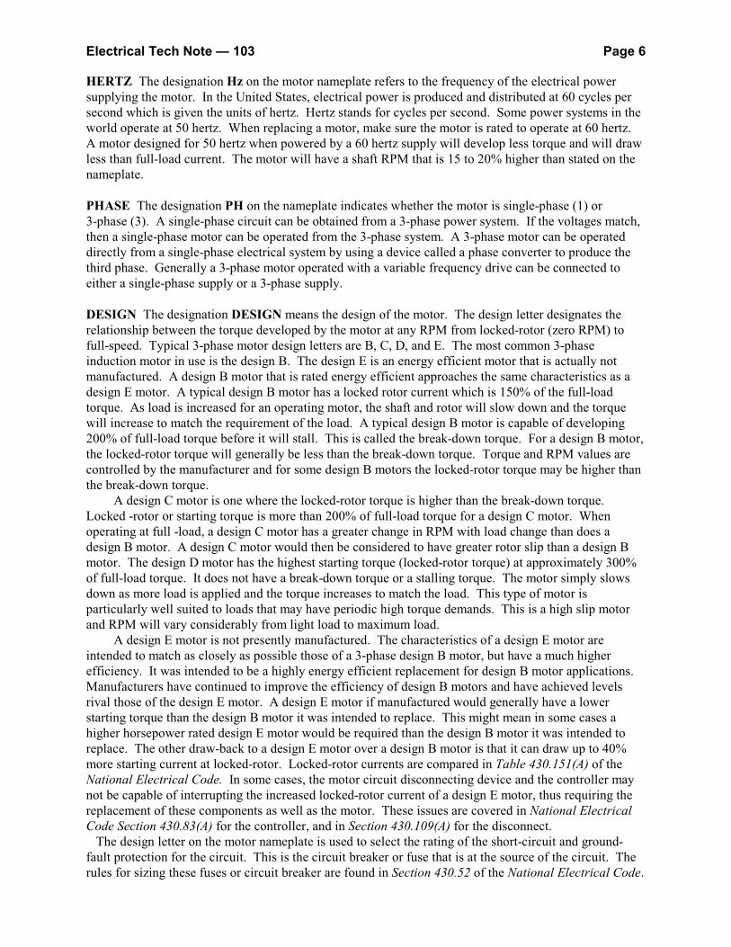
Single-phase motors have design letters are different than for 3-phase motors. Single-phase motorsoften have a starting winding that is disconnected when the motor approaches operating RPM. The shapeof the torque - RPM curves are different than those in Figure 5. Important considerations when selectinga single-phase motor are locked-rotor torque, break-down torque, and full-load torque. Single-phasemotors are generally described based upon the type of starting. For example, a common single-phasemotor is a capacitor start-induction run motor. This type has moderate starting torque. On the otherhand, a split-phase start, induction run motor has low starting torque.
Figure 5 Torque verses RPM curves are compared for the three common designs of3-phase motors with equal horsepower ratings.
INSULATION CLASS The motor nameplate of Figure 1 shows the words INS CLASS. This refers tothe thin insulation which is on the windings inside the motor. The insulation is simply a coating on thewindings which is very thin. The insulation must be thin in order to get many wires into the small slotscut into the motor frame. The insulation class refers to the maximum temperature which the insulationcan withstand before it begins to break down. If the insulation breaks down, the motor will fail. Overloading the motor will cause the current to increase through the windings. The increased currentcauses heat which raises the winding temperature. The windings must always operate below thebreak-down temperature of the winding insulation.
Most general purpose motors have an insulation class of A, B, or F. Class A insulation has thelowest break-down temperature which is approximately 105EC. Class B insulation has a higherbreak-down temperature which is approximately 130EC. This is one case when B is better than A. ClassA and B insulation are common for single-phase motors. Class F insulation is common for 3-phasemotors. The break-down temperature for class F insulation is approximately 155EC. In situations wherean electric motor is exposed to a high ambient temperature, a motor can be equipped with class Hinsulation which has an approximate break-down temperature of 180E.
SERVICE FACTOR The service factor, S. F. on the nameplate of Figure 1, is an indication of theoverload capacity of the motor. The service factor of the motor with the nameplate in Figure 1 is 1.15. This means that the motor can operate at a 15% overload without damaging the motor. Motors with highservice factors are recommended for farm and many industrial applications where the load on the motormay increase. A service factor of 1.15 or larger is recommended for farm applications. If a motor has aservice factor of 1.0, then the motor has no overload capacity. If the motor is overloaded for a period oftime, the motor will probably overheat.
Electrical Tech Note — 103 Page 8
The service factor and the nameplate full-load current are used to determine the rating of the motoroverload sensing element. The rules for sizing the overload sensing elements for a motor are found inSection 430.32 of the National Electrical Code. Manufacturers of motor controllers provide overloadsensing elements that protect a motor from overloads. The nameplate full-load current is used to selectthe manufacturer part number for the overload sensing element needed for a specific motor. A detailedexplanation of how to size the components of an electric motor branch circuit are described in the textInterpreting the National Electrical Code. (see references at the end)
CODE The code letter can be used to figure out how much current a motor will draw the instant it isstarted, or when the motor stalls with the rotor not turning. These conditions are called locked rotor. Locked rotor current drawn by the motor must be considered by an electrician when installing a motorcircuit. The higher the code letter, the more starting current the motor requires. For example, considertwo motors of the same horsepower. Motors with a code letter L will have a higher starting current thana motor with a code letter E. Code letter is not required to be given on a motor nameplate. In the pastthe code letter, not the design letter, was used to select the maximum rating permitted for the branch-circuit short-circuit and ground-fault protection for a motor circuit.
The code letter may be a clue as to why the fuse blows or the circuit breaker trips when the newmotor tries to start the load. If the replacement motor has a higher code letter than the original motor, itwill draw a higher starting current, thus possibly causing the fuse to blow or circuit breaker to trip. Ifyou think this can be the problem, the situation can be corrected by an electrician.
EFFICIENCY The full-load efficiency is being marked on the nameplate of many motors. Efficiency isthe percentage of power drawn by an electric motor that is supplied to the shaft as mechanical power. Since 1997 manufacturers have been required to build motors meeting minimum efficiency standards. Many motors are built to a high efficiency standard and are listed on the nameplate as PremiumEfficiency motors. Efficiency marked on the nameplate of motors is at full-load. If a motor is poweringa load which requires much less horsepower than the motor is rated to deliver, the efficiency will bemuch less. A motor which is too large for the load is usually operating with a very low efficiency. It isimportant for motors to be matched to the load. Since many motors are powering highly variable loads,variable frequency drives are being used in many cases to control the speed of motors so they are alwaysoperating at their peak efficiency.
POWER FACTOR The letters P.F when marked on the nameplate of some motors means the powerfactor. This is a term which is useful to an electrician. This usually is not information which is neededwhen selecting a replacement motor. Power factor will range from 0 to 1.0. A motor will a low powerfactor will draw more current for the same horsepower than a motor with a high power factor.
AMBIENT TEMPERATURE The motor nameplate of Figure 1 has a designation RATING. Withinthat space is a marking 40EC AMB. This means that the motor is designed to operate with a ambient orsurrounding temperature of not more than 40 degrees on the Celsius scale. That is 104EF. If the motorwill operate in an area where the temperature frequently exceeds 104EF, then the motor may overheat ifoperated at full load as marked on the nameplate. If a motor burns-out frequently, find out if it frequentlyoperates in an area where the temperature is very high. If this is the case, then one solution may be tooversize the motor for the load. Another solution may be to choose a motor with class F or H insulationwhich has a high break-down temperature.
DUTY The motor nameplate in Figure 1 does not have a space marked DUTY. Instead, the informationis shown in the space following rating. The marking CONTINUOUS means that this is a continuous dutymotor. The motor is designed to operate for long periods of time. If the motor is not continuous duty,the duty cycle will be marked on the nameplate. For example, an intermittent duty motor may be markedto operate only 12 minutes per hour.
Electrical Tech Note — 103 Page 9
ENCLOSURES The type of motor enclosure is extremely important when it comes to certainapplications. Dust, dirt and combustible materials that may be present in an location must be consideredwhen selecting a motor.
An open motor is one that has ventilation openings that will permit the passage of air over andaround the windings of the motor. Fan blades on the rotor force air over the windings. Open motors maybe drip-proof or splash proof. The Open Drip-Proof (ODP) enclosure, allows air passage through themotor but the openings are arraigned so falling liquids such as rain will not enter through the openings. Open motors are not recommended for use in building where excessive dust is present, such as anagricultural building.
Totally enclosed motors should be installed in areas where dust may settle on the motor. Air is notdrawn into the motor for cooling. Totally enclosed motors may be cooled by a fan, Totally EnclosedFan-Cooled (TEFC) or by natural convection, Totally Enclosed Non-Ventilated. (TENV). The totallyenclosed fan-cooled motor is similar to the non-ventilated motor except an external fan mounted on theend opposite the shaft blows air over the exterior housing of the motor. While these motors are enclosed,they are not air tight gasses and vapors can enter through the seals of the motor housing. In areas wherecombustible gases or dusts are present explosion proof motors must be selected.
CONNECTING AND REVERSING SINGLE-PHASE MOTORS
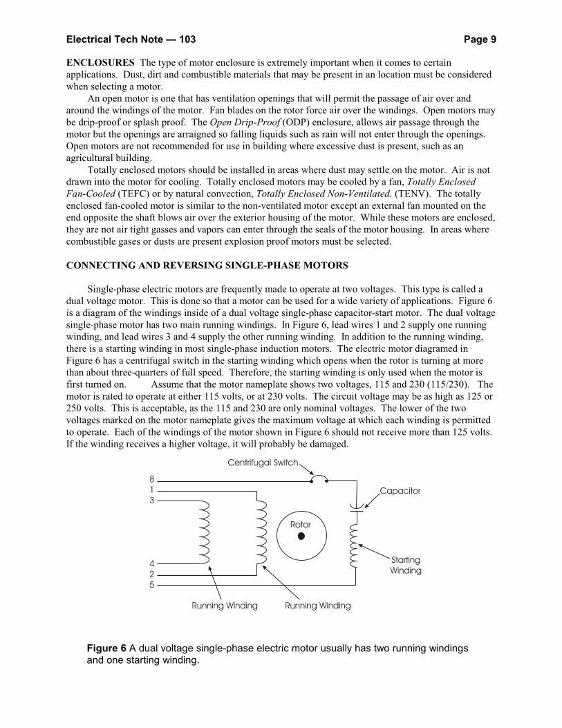
Single-phase electric motors are frequently made to operate at two voltages. This type is called adual voltage motor. This is done so that a motor can be used for a wide variety of applications. Figure 6is a diagram of the windings inside of a dual voltage single-phase capacitor-start motor. The dual voltagesingle-phase motor has two main running windings. In Figure 6, lead wires 1 and 2 supply one runningwinding, and lead wires 3 and 4 supply the other running winding. In addition to the running winding,there is a starting winding in most single-phase induction motors. The electric motor diagramed inFigure 6 has a centrifugal switch in the starting winding which opens when the rotor is turning at morethan about three-quarters of full speed. Therefore, the starting winding is only used when the motor isfirst turned on. Assume that the motor nameplate shows two voltages, 115 and 230 (115/230). Themotor is rated to operate at either 115 volts, or at 230 volts. The circuit voltage may be as high as 125 or250 volts. This is acceptable, as the 115 and 230 are only nominal voltages. The lower of the twovoltages marked on the motor nameplate gives the maximum voltage at which each winding is permittedto operate. Each of the windings of the motor shown in Figure 6 should not receive more than 125 volts. If the winding receives a higher voltage, it will probably be damaged.
Figure 6 A dual voltage single-phase electric motor usually has two running windingsand one starting winding.
Electrical Tech Note — 103 Page 10
Low Voltage Motor Connections
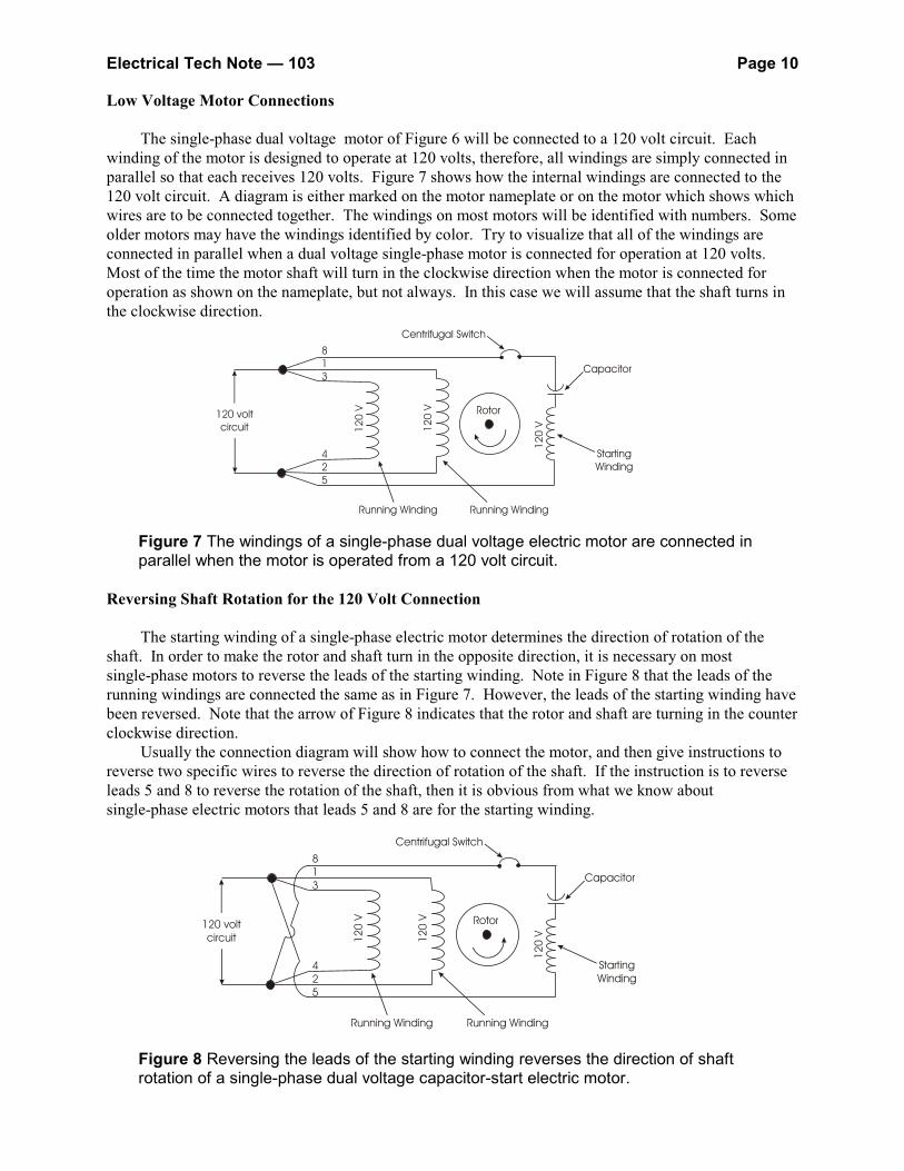
The single-phase dual voltage motor of Figure 6 will be connected to a 120 volt circuit. Eachwinding of the motor is designed to operate at 120 volts, therefore, all windings are simply connected inparallel so that each receives 120 volts. Figure 7 shows how the internal windings are connected to the120 volt circuit. A diagram is either marked on the motor nameplate or on the motor which shows whichwires are to be connected together. The windings on most motors will be identified with numbers. Someolder motors may have the windings identified by color. Try to visualize that all of the windings areconnected in parallel when a dual voltage single-phase motor is connected for operation at 120 volts. Most of the time the motor shaft will turn in the clockwise direction when the motor is connected foroperation as shown on the nameplate, but not always. In this case we will assume that the shaft turns inthe clockwise direction.
Figure 7 The windings of a single-phase dual voltage electric motor are connected inparallel when the motor is operated from a 120 volt circuit.
Reversing Shaft Rotation for the 120 Volt Connection
The starting winding of a single-phase electric motor determines the direction of rotation of theshaft. In order to make the rotor and shaft turn in the opposite direction, it is necessary on mostsingle-phase motors to reverse the leads of the starting winding. Note in Figure 8 that the leads of therunning windings are connected the same as in Figure 7. However, the leads of the starting winding havebeen reversed. Note that the arrow of Figure 8 indicates that the rotor and shaft are turning in the counterclockwise direction.
Usually the connection diagram will show how to connect the motor, and then give instructions toreverse two specific wires to reverse the direction of rotation of the shaft. If the instruction is to reverseleads 5 and 8 to reverse the rotation of the shaft, then it is obvious from what we know aboutsingle-phase electric motors that leads 5 and 8 are for the starting winding.
Figure 8 Reversing the leads of the starting winding reverses the direction of shaftrotation of a single-phase dual voltage capacitor-start electric motor.
Electrical Tech Note — 103 Page 11
High Voltage Motor Connections
The dual voltage single-phase motor has windings which are not permitted to be operated at morethan about 120 volts. If the supply circuit is operated at 240 volts, then the motor cannot be connected asshown in Figure 7 or Figure 8 or the windings will receive 240 volts instead of 120 volts.
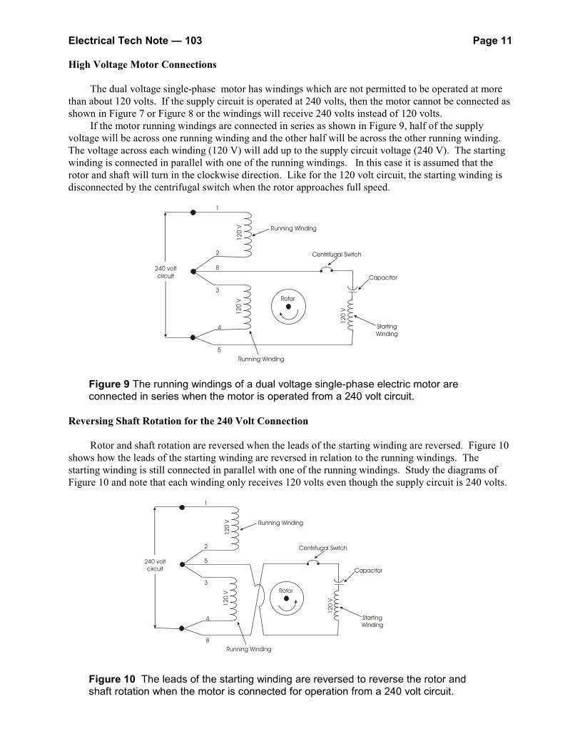
If the motor running windings are connected in series as shown in Figure 9, half of the supplyvoltage will be across one running winding and the other half will be across the other running winding. The voltage across each winding (120 V) will add up to the supply circuit voltage (240 V). The startingwinding is connected in parallel with one of the running windings. In this case it is assumed that therotor and shaft will turn in the clockwise direction. Like for the 120 volt circuit, the starting winding isdisconnected by the centrifugal switch when the rotor approaches full speed.
Figure 9 The running windings of a dual voltage single-phase electric motor areconnected in series when the motor is operated from a 240 volt circuit.
Reversing Shaft Rotation for the 240 Volt Connection
Rotor and shaft rotation are reversed when the leads of the starting winding are reversed. Figure 10shows how the leads of the starting winding are reversed in relation to the running windings. Thestarting winding is still connected in parallel with one of the running windings. Study the diagrams ofFigure 10 and note that each winding only receives 120 volts even though the supply circuit is 240 volts.
Figure 10 The leads of the starting winding are reversed to reverse the rotor andshaft rotation when the motor is connected for operation from a 240 volt circuit.
Electrical Tech Note — 103 Page 12
Reversing Shaft Rotation for 3-Phase Motors
A 3-phase induction motor requires three wires from a 3-phase electrical system. The wires areidentified by the letters A, B, and C. Usually all three wires are ungrounded (hot), but on some electricalsystems one of the wires is grounded to the earth. In all cases, a safety equipment grounding conductor isalso run to the frame of the motor.
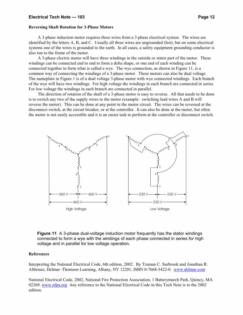
A 3-phase electric motor will have three windings in the outside or stator part of the motor. Thesewindings can be connected end to end to form a delta shape, or one end of each winding can beconnected together to form what is called a wye. The wye connection, as shown in Figure 11, is acommon way of connecting the windings of a 3-phase motor. These motors can also be dual voltage. The nameplate in Figure 1 is of a dual voltage 3-phase motor with wye connected windings. Each branchof the wye will have two windings. For high voltage the windings in each branch are connected in series. For low voltage the windings in each branch are connected in parallel.
The direction of rotation of the shaft of a 3-phase motor is easy to reverse. All that needs to be doneis to switch any two of the supply wires to the motor (example: switching lead wires A and B willreverse the motor). This can be done at any point in the motor circuit. The wires can be reversed at thedisconnect switch, at the circuit breaker, or at the controller. It can also be done at the motor, but oftenthe motor is not easily accessible and it is an easier task to perform at the controller or disconnect switch.
Figure 11 A 3-phase dual-voltage induction motor frequently has the stator windingsconnected to form a wye with the windings of each phase connected in series for highvoltage and in parallel for low voltage operation.
References
Interpreting the National Electrical Code, 6th edition, 2002. By Truman C. Surbrook and Jonathan R.Althouse, Delmar–Thomson Learning, Albany, NY 12201, ISBN 0-7668-3422-0. www.delmar.com
National Electrical Code, 2002, National Fire Protection Association, 1 Batterymarch Park, Quincy, MA02269. www.nfpa.org Any reference to the National Electrical Code in this Tech Note is to the 2002edition.


![Electrical Tech Specification[1]](https://img.pdfslide.us/doc/110x75/54f5eab94a79596c4a8b4a41/electrical-tech-specification1.jpg)