Embed Size (px)
Citation preview
IntroductionIntroduction
©2012 Cooper Bussmann
Electrical Safety ™
IntroductionThere is a great deal of activity in the electrical industry concerning electricalsafety. The present focus is on two of the greatest electrical hazards to workers: shock and arc flash. In recent years, significant knowledge has beengained through testing and analysis concerning arc flash hazards and how tocontend with this type of hazard. Note: a third electrical hazard is arc blast andwork is ongoing to learn more about how to deal with this electrical hazard.NFPA 70E “Standard for Electrical Safety in the Workplace,” 2012 Edition, isthe foremost consensus standard on electrical safety. References to NFPA70E in this section are to the 2012 NFPA 70E.
Why is there an NFPA 70E?In 1976 a new electrical standards development committee was formed toassist the Occupational Safety and Health Administration (OSHA) in preparingelectrical safety standards. This committee on Electrical Safety Requirementsfor Employee Workplaces, NFPA 70E, was needed for a number of reasons,including:
1. The NEC® is an installation standard while OSHA addresses employee safety in the workplace,
2. Most sections in the NEC® do not relate to worker safety 3. Safety related work and maintenance practices are generally not covered, or not adequately covered, in the NEC® and
4. A national consensus standard on electrical safety for workers did not exist, but was needed – an easy to understand document that addresses worker electrical safety.
The first edition of NFPA 70E was published in 1979. In most cases, OSHAregulations can be viewed as the Why and NFPA 70E as the How. AlthoughOSHA and NFPA 70E may use slightly different language, in essence, NFPA70E does not require anything that is not already an OSHA regulation. Inmost cases, OSHA is performance language and NFPA 70E is prescriptivelanguage.
If an arcing fault occurs, the tremendous energy released in a fraction of asecond can result in serious injury or death. NFPA 70E, Article 100, defines anarc flash hazard as:
a dangerous condition associated with the possible release of energy caused by an electric arc.
The first informational note to this definition indicates that an arc flash hazardmay exist when electrical conductors or circuit parts, which are not in an electrically safe work condition, are exposed or may exist if a person is interacting with the equipment even when the conductors or circuit parts withinequipment are in a guarded or enclosed condition.
While awareness of arc flash hazards is increasing, there is a great challengein communicating the message to the populace of the electrical industry sothat safer system designs and safer work procedures and behaviors result.Workers continue to suffer life altering injuries or death.
Only Work On Equipment That Is In AnElectrically Safe Work ConditionThe rule for the industry and the law is “don’t work it hot,” OSHA1910.333(a)(1) requires live parts to be deenergized before an employeeworks on or near them except for two demonstrable reasons by the employer:
1. Deenergizing introduces additional or increased hazards (such as cutting ventilation to a hazardous location) or
2. Infeasible due to equipment design or operational limitations (such as when voltage testing is required for diagnostics).
Similarly, NFPA 70E 130.2 requires energized electrical conductors and circuitparts to be put in an electrically safe work condition before an employee works
within the Limited Approach Boundary of those conductors or parts or theemployee interacts with parts that are not exposed but an increased arc flashhazard exists, unless justified in accordance with NFPA 70E 130.2(A). NFPA70E, Article 100, defines an electrically safe work condition as:
A state in which an electrical conductor or circuit part has been disconnected from energized parts, locked/tagged in accordance with established standards, tested to ensure the absence of voltage, and grounded if deteremined necessary.
NFPA 70E 130.3(A)(2) requires work on electrical conductors or circuit partsnot in an electrically safe work condition to be performed by only qualified persons. In some situations, an arc flash hazard may exist beyond theLimited Approach Boundary. It is advisable to use the greater distance ofeither the Limited Approach Boundary or the arc flash Protection Boundary incomplying with NFPA 130.3(A)(2).
NFPA 70E 130.2(A)(1) permits energized work if the employer can demonstrate energized work introduces additional or increased hazards or perNFPA 130.2(A)(2) if the task to be performed is infeasible in a deenergizedstate due to equipment design or operational limitations. Financial considerations are not an adequate reason to perform energized work. Notcomplying with these regulations and practices is a violation of federal law,which is punishable by fine and/or imprisonment.
When energized work is justified per NFPA 70E 130.2(A)(1) or (A)(2), NFPA70E 130.3(B)(1) requires an electrical hazard analysis (shock hazard analysisin accordance with NFPA 70E 130.4(A) and an arc flash hazard analysis inaccordance with NFPA 70E 130.5). A written energized electrical work permitmay also be required per NFPA 70E 130.2(B)(1). When an energized electrical work permit is required, it must include items as shown in NFPA 70E130.2(B)(2). Some key items of the energized electrical work permit includedetermination of the shock protection boundaries in accordance with NFPA70E 130.4(B), the arc flash Protection Boundary in accordance with NFPA 70E130.5, and the necessary protective clothing and other Personal ProtectiveEquipment (PPE) in accordance with NFPA 70E 130.5. Similarly, OSHA1910.132(d)(2) requires the employer to verify that the required workplacehazard assessment has been performed through a written certification thatidentifies the workplace evaluated; the person certifying that the evaluation has been performed; the date(s) of the hazard assessment; and,identifies the document as a certification of hazard assessment.
Note: deenergized electrical parts are considered as energized until all stepsof the lockout/tagout procedure are successfully completed per OSHA1910.333(b)(1). Similarly, all electrical conductors and circuit parts must beconsidered to not be in an electrically safe work condition until all the requirements of Article 120 have been met per NFPA 70E 120.2(A).
Verifying that the circuit elements and equipment parts are deenergized by aqualified person is a required step while completing the lockout/tagout procedure per OSHA 1910.333(b)(2)(iv)(B). Conductors and parts of electricequipment that have been deenergized but have not been locked out ortagged and proven to be deenergized are required to be treated as energizedparts per 1910.333(b)(1). Similarly NFPA 70E 120.2(A) requires that all electrical conductors and circuit parts are not considered to be in an electrically safe work condition - until the entire process of establishing theelectrically safe work condition is met.
Therefore, adequate PPE is always required during the tests to verify theabsence of voltage during the lockout/tagout procedure or when putting equipment in an electrically safe work condition. Adequate PPE may also berequired during load interruption and during visual inspection that verifies alldisconnecting devices are open.
158
Shock Hazard Analysis
No matter how well a worker follows safe work practices, there will always bea risk associated with interacting with electrical equipment – even whenputting equipment in an electrically safe work condition. And there are thoseoccasions where it is necessary to work on energized equipment such aswhen a problem can not be uncovered by troubleshooting the equipment in adeenergized state.
What Can Be Done To Lessen the Risk?There are numerous things that can be implemented to increase electricalsafety, from design aspects and upgrading systems, to training, implementingsafe work practices and utilizing PPE. Not all of these topics can be coveredin this section. The focus of this section will mainly concern some overcurrentprotection aspects related to electrical safety.
Shock Hazard AnalysisThe Shock Hazard Analysis per NFPA 70E 130.4(A) requires the determination of the voltage exposure as well as the boundary requirementsand the PPE necessary to minimize the possibility of electric shock. There arethree shock approach boundaries required to be observed in NFPA 70E Table130.4(C)(a); these shock approach boundaries are dependent upon the system voltage. The significance of these boundaries for workers and theiractions while within the boundaries can be found in NFPA 70E. See Figure 2for a graphic depiction of the three shock approach boundaries with the arc flash protection boundary (following the section on arc flash HazardAssessment). For electrical hazard analysis and worker protection, it is important to observe the shock approach boundaries together with the arc flash protection boundary (which is covered in paragraphs ahead).
DisconnectsSami Covers
Safety J HoldersCUBEFuse™
CH Series Holders
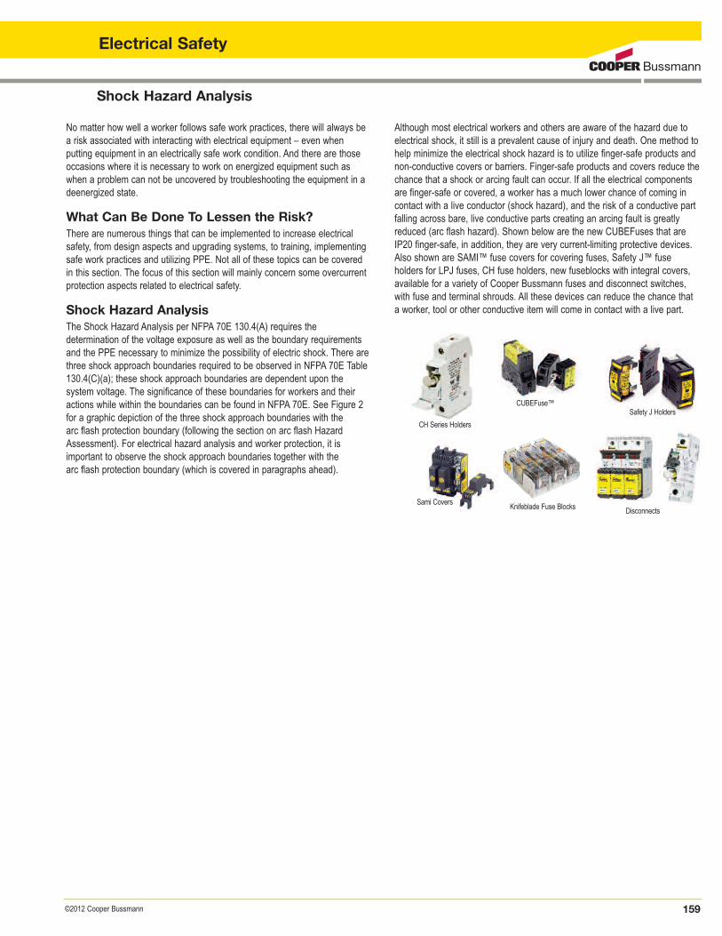
Although most electrical workers and others are aware of the hazard due toelectrical shock, it still is a prevalent cause of injury and death. One method tohelp minimize the electrical shock hazard is to utilize finger-safe products andnon-conductive covers or barriers. Finger-safe products and covers reduce thechance that a shock or arcing fault can occur. If all the electrical componentsare finger-safe or covered, a worker has a much lower chance of coming incontact with a live conductor (shock hazard), and the risk of a conductive partfalling across bare, live conductive parts creating an arcing fault is greatlyreduced (arc flash hazard). Shown below are the new CUBEFuses that areIP20 finger-safe, in addition, they are very current-limiting protective devices.Also shown are SAMI™ fuse covers for covering fuses, Safety J™ fuse holders for LPJ fuses, CH fuse holders, new fuseblocks with integral covers,available for a variety of Cooper Bussmann fuses and disconnect switches,with fuse and terminal shrouds. All these devices can reduce the chance thata worker, tool or other conductive item will come in contact with a live part.
159©2012 Cooper Bussmann
Electrical Safety
Knifeblade Fuse Blocks
Arc Flash Protection
160 ©2012 Cooper Bussmann
Electrical Safety
Arc Fault BasicsAn electrician that is working in an energized panelboard or just putting equipmentinto an electrically safe work condition is potentially in a very unsafe place. A fallingknockout, a dislodged skinned wire scrap inadvertently left previously in the panelboard or a slip of a screwdriver can cause an arcing fault. The temperature ofthe arc can reach approximately 35,000°F, or about four times as hot as the surface of the sun. These temperatures easily can cause serious or fatal burnsand/or ignite flammable clothing.
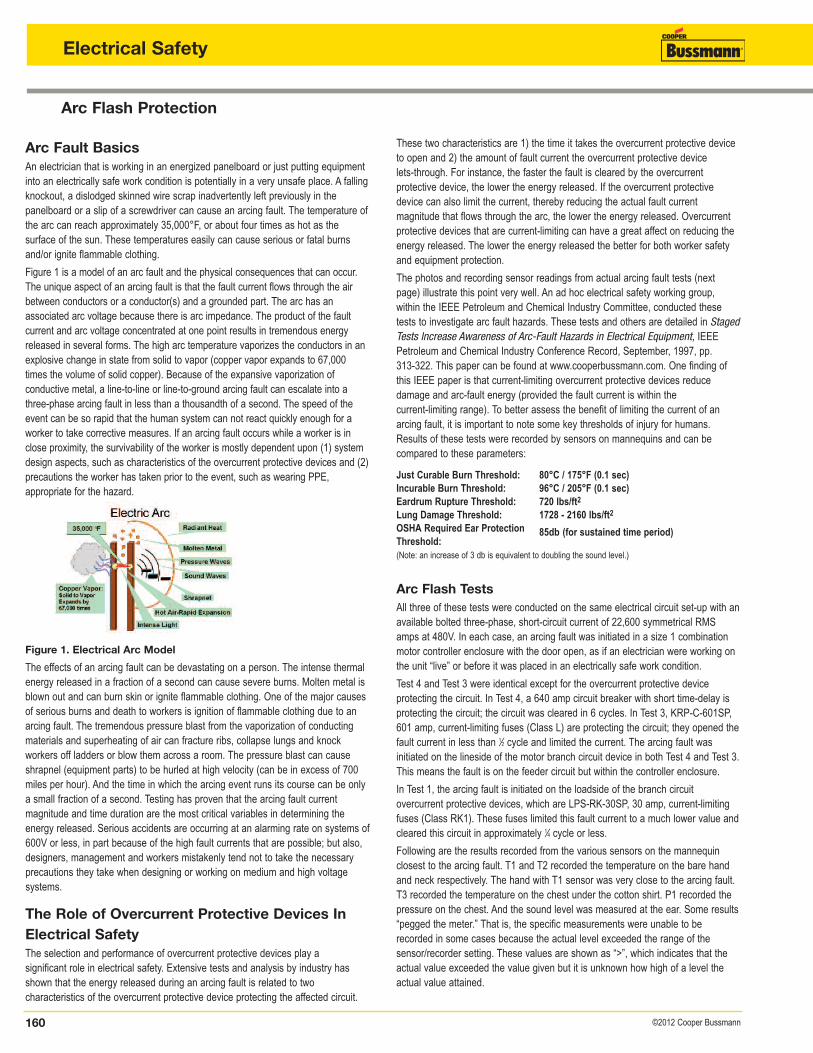
Figure 1 is a model of an arc fault and the physical consequences that can occur.The unique aspect of an arcing fault is that the fault current flows through the airbetween conductors or a conductor(s) and a grounded part. The arc has an associated arc voltage because there is arc impedance. The product of the fault current and arc voltage concentrated at one point results in tremendous energyreleased in several forms. The high arc temperature vaporizes the conductors in anexplosive change in state from solid to vapor (copper vapor expands to 67,000times the volume of solid copper). Because of the expansive vaporization of conductive metal, a line-to-line or line-to-ground arcing fault can escalate into athree-phase arcing fault in less than a thousandth of a second. The speed of theevent can be so rapid that the human system can not react quickly enough for aworker to take corrective measures. If an arcing fault occurs while a worker is inclose proximity, the survivability of the worker is mostly dependent upon (1) systemdesign aspects, such as characteristics of the overcurrent protective devices and (2)precautions the worker has taken prior to the event, such as wearing PPE, appropriate for the hazard.
Figure 1. Electrical Arc ModelThe effects of an arcing fault can be devastating on a person. The intense thermalenergy released in a fraction of a second can cause severe burns. Molten metal isblown out and can burn skin or ignite flammable clothing. One of the major causesof serious burns and death to workers is ignition of flammable clothing due to anarcing fault. The tremendous pressure blast from the vaporization of conductingmaterials and superheating of air can fracture ribs, collapse lungs and knock workers off ladders or blow them across a room. The pressure blast can causeshrapnel (equipment parts) to be hurled at high velocity (can be in excess of 700miles per hour). And the time in which the arcing event runs its course can be onlya small fraction of a second. Testing has proven that the arcing fault current magnitude and time duration are the most critical variables in determining the energy released. Serious accidents are occurring at an alarming rate on systems of600V or less, in part because of the high fault currents that are possible; but also,designers, management and workers mistakenly tend not to take the necessaryprecautions they take when designing or working on medium and high voltage systems.
The Role of Overcurrent Protective Devices InElectrical SafetyThe selection and performance of overcurrent protective devices play a significant role in electrical safety. Extensive tests and analysis by industry hasshown that the energy released during an arcing fault is related to two characteristics of the overcurrent protective device protecting the affected circuit.
These two characteristics are 1) the time it takes the overcurrent protective deviceto open and 2) the amount of fault current the overcurrent protective device lets-through. For instance, the faster the fault is cleared by the overcurrent protective device, the lower the energy released. If the overcurrent protectivedevice can also limit the current, thereby reducing the actual fault current magnitude that flows through the arc, the lower the energy released. Overcurrentprotective devices that are current-limiting can have a great affect on reducing theenergy released. The lower the energy released the better for both worker safetyand equipment protection.
The photos and recording sensor readings from actual arcing fault tests (nextpage) illustrate this point very well. An ad hoc electrical safety working group, within the IEEE Petroleum and Chemical Industry Committee, conducted thesetests to investigate arc fault hazards. These tests and others are detailed in StagedTests Increase Awareness of Arc-Fault Hazards in Electrical Equipment, IEEEPetroleum and Chemical Industry Conference Record, September, 1997, pp. 313-322. This paper can be found at www.cooperbussmann.com. One finding ofthis IEEE paper is that current-limiting overcurrent protective devices reduce damage and arc-fault energy (provided the fault current is within the current-limiting range). To better assess the benefit of limiting the current of an arcing fault, it is important to note some key thresholds of injury for humans.Results of these tests were recorded by sensors on mannequins and can be compared to these parameters:
Just Curable Burn Threshold: 80°C / 175°F (0.1 sec)Incurable Burn Threshold: 96°C / 205°F (0.1 sec)Eardrum Rupture Threshold: 720 lbs/ft2
Lung Damage Threshold: 1728 - 2160 lbs/ft2
OSHA Required Ear ProtectionThreshold:
85db (for sustained time period)
(Note: an increase of 3 db is equivalent to doubling the sound level.)
Arc Flash TestsAll three of these tests were conducted on the same electrical circuit set-up with anavailable bolted three-phase, short-circuit current of 22,600 symmetrical RMSamps at 480V. In each case, an arcing fault was initiated in a size 1 combinationmotor controller enclosure with the door open, as if an electrician were working onthe unit “live” or before it was placed in an electrically safe work condition.
Test 4 and Test 3 were identical except for the overcurrent protective device protecting the circuit. In Test 4, a 640 amp circuit breaker with short time-delay isprotecting the circuit; the circuit was cleared in 6 cycles. In Test 3, KRP-C-601SP,601 amp, current-limiting fuses (Class L) are protecting the circuit; they opened thefault current in less than 1⁄2 cycle and limited the current. The arcing fault was initiated on the lineside of the motor branch circuit device in both Test 4 and Test 3.This means the fault is on the feeder circuit but within the controller enclosure.
In Test 1, the arcing fault is initiated on the loadside of the branch circuit overcurrent protective devices, which are LPS-RK-30SP, 30 amp, current-limitingfuses (Class RK1). These fuses limited this fault current to a much lower value andcleared this circuit in approximately 1⁄4 cycle or less.
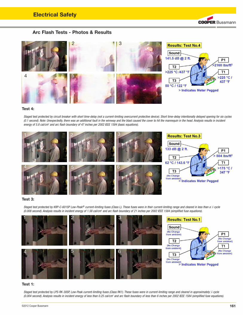
Following are the results recorded from the various sensors on the mannequinclosest to the arcing fault. T1 and T2 recorded the temperature on the bare handand neck respectively. The hand with T1 sensor was very close to the arcing fault.T3 recorded the temperature on the chest under the cotton shirt. P1 recorded thepressure on the chest. And the sound level was measured at the ear. Some results“pegged the meter.” That is, the specific measurements were unable to be recorded in some cases because the actual level exceeded the range of the sensor/recorder setting. These values are shown as “>”, which indicates that theactual value exceeded the value given but it is unknown how high of a level theactual value attained.
Arc Flash Tests - Photos & Results
Test 4:Staged test protected by circuit breaker with short time-delay (not a current-limiting overcurrent protective device). Short time-delay intentionally delayed opening for six cycles (0.1 second). Note: Unexpectedly, there was an additional fault in the wireway and the blast caused the cover to hit the mannequin in the head. Analysis results in incident energy of 5.8 cal/cm2 and arc flash boundary of 47 inches per 2002 IEEE 1584 (basic equations).
Test 3:Staged test protected by KRP-C-601SP Low-Peak® current-limiting fuses (Class L). These fuses were in their current-limiting range and cleared in less than a 1⁄2 cycle (0.008 second). Analysis results in incident energy of 1.58 cal/cm2 and arc flash boundary of 21 inches per 2002 IEEE 1584 (simplified fuse equations).
Test 1:Staged test protected by LPS-RK-30SP, Low-Peak current-limiting fuses (Class RK1). These fuses were in current-limiting range and cleared in approximately 1⁄4 cycle (0.004 second). Analysis results in incident energy of less than 0.25 cal/cm2 and arc flash boundary of less than 6 inches per 2002 IEEE 1584 (simplified fuse equations).
1 2 3
4 5 6
1 2 3
4 5 6
1 2 3
4 5 6
161©2012 Cooper Bussmann
Electrical Safety
Arc Flash Protection
162 ©2012 Cooper Bussmann
Electrical Safety
A couple of conclusions can be drawn from this testing.
(1) Arcing faults can release tremendous amounts of energy in many forms in a veryshort period of time. Look at all the measured values compared to key thresholdsof injury for humans given in a previous paragraph. Test 4 was protected by a 640A, non current-limiting device that opened in 6 cycles or 0.1 second.
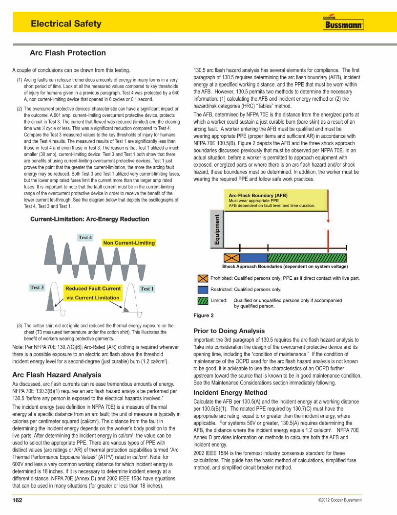
(2) The overcurrent protective devices’ characteristic can have a significant impact onthe outcome. A 601 amp, current-limiting overcurrent protective device, protectsthe circuit in Test 3. The current that flowed was reduced (limited) and the clearingtime was 1⁄2 cycle or less. This was a significant reduction compared to Test 4.Compare the Test 3 measured values to the key thresholds of injury for humansand the Test 4 results. The measured results of Test 1 are significantly less thanthose in Test 4 and even those in Test 3. The reason is that Test 1 utilized a muchsmaller (30 amp), current-limiting device. Test 3 and Test 1 both show that thereare benefits of using current-limiting overcurrent protective devices. Test 1 justproves the point that the greater the current-limitation, the more the arcing faultenergy may be reduced. Both Test 3 and Test 1 utilized very current-limiting fuses,but the lower amp rated fuses limit the current more than the larger amp ratedfuses. It is important to note that the fault current must be in the current-limitingrange of the overcurrent protective device in order to receive the benefit of thelower current let-through. See the diagram below that depicts the oscillographs ofTest 4, Test 3 and Test 1.
Non Current-Limiting
Test 1
Test 4
Test 3 Reduced Fault Current
via Current Limitation
Current-Limitation: Arc-Energy ReductionCurrent-Limitation: Arc-Energy ReductionCurrent-Limitation: Arc-Energy Reduction
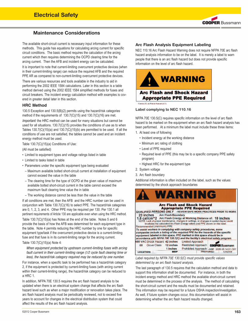
Arc-Flash Boundary (AFB)Must wear appropriate PPEAFB dependent on fault level and time duration.
Eq
uip
men
t
Shock Approach Boundaries (dependent on system voltage)
Prohibited: Qualified persons only; PPE as if direct contact with live part.
Restricted: Qualified persons only.
Limited: Qualified or unqualified persons only if accompanied by qualified person.
(3) The cotton shirt did not ignite and reduced the thermal energy exposure on thechest (T3 measured temperature under the cotton shirt). This illustrates the benefit of workers wearing protective garments.
Note: Per NFPA 70E 130.7(C)(6): Arc-Rated (AR) clothing is required whereverthere is a possible exposure to an electric arc flash above the threshold incident energy level for a second-degree (just curable) burn (1.2 cal/cm2).
Arc Flash Hazard AnalysisAs discussed, arc flash currents can release tremendous amounts of energy.NFPA 70E 130.3(B)(1) requires an arc flash hazard analysis be performed per130.5 “before any person is exposed to the electrical hazards involved.”
The incident energy (see definition in NFPA 70E) is a measure of thermal energy at a specific distance from an arc fault; the unit of measure is typically incalories per centimeter squared (cal/cm2). The distance from the fault in determining the incident energy depends on the worker’s body position to thelive parts. After determining the incident energy in cal/cm2, the value can beused to select the appropriate PPE. There are various types of PPE with distinct values (arc ratings or AR) of thermal protection capabilities termed “ArcThermal Performance Exposure Values” (ATPV) rated in cal/cm2. Note: for600V and less a very common working distance for which incident energy isdetermined is 18 inches. If it is necessary to determine incident energy at a different distance, NFPA 70E (Annex D) and 2002 IEEE 1584 have equationsthat can be used in many situations (for greater or less than 18 inches).
130.5 arc flash hazard analysis has several elements for compliance. The firstparagraph of 130.5 requires determining the arc flash boundary (AFB), incidentenergy at a specified working distance, and the PPE that must be worn withinthe AFB. However, 130.5 permits two methods to determine the necessaryinformation: (1) calculating the AFB and incident energy method or (2) the hazard/risk categories (HRC) “Tables” method.
The AFB, determined by NFPA 70E is the distance from the energized parts atwhich a worker could sustain a just curable burn (bare skin) as a result of anarcing fault. A worker entering the AFB must be qualified and must be wearing appropriate PPE (proper items and sufficient AR) in accordance withNFPA 70E 130.5(B). Figure 2 depicts the AFB and the three shock approachboundaries discussed previously that must be observed per NFPA 70E. In anactual situation, before a worker is permitted to approach equipment withexposed, energized parts or where there is an arc flash hazard and/or shockhazard, these boundaries must be determined. In addition, the worker must bewearing the required PPE and follow safe work practices.
Prior to Doing AnalysisImportant: the 3rd paragraph of 130.5 requires the arc flash hazard analysis to“take into consideration the design of the overcurrent protective device and itsopening time, including the “condition of maintenance.” If the condition of maintenance of the OCPD used for the arc flash hazard analysis is not knownto be good, it is advisable to use the characteristics of an OCPD furtherupstream toward the source that is known to be in good maintenance condition.See the Maintenance Considerations section immediately following.
Incident Energy MethodCalculate the AFB per 130.5(A) and the incident energy at a working distanceper 130.5(B)(1). The related PPE required by 130.7(C) must have the appropriate arc rating equal to or greater than the incident energy, whereapplicable. For systems 50V or greater, 130.5(A) requires determining theAFB, the distance where the incident energy equals 1.2 cals/cm2. NFPA 70EAnnex D provides information on methods to calculate both the AFB and incident energy.
2002 IEEE 1584 is the foremost industry consensus standard for these calculations. This guide has the basic method of calculations, simplified fusemethod, and simplified circuit breaker method.
Figure 2
Maintenance Considerations
The available short-circuit current is necessary input information for thesemethods. This guide has equations for calculating arcing current for specificcircuit conditions. The basic method requires the calculation of the arcing current which then requires determining the OCPD clearing time for the arcing current. Then the AFB and incident energy can be calculated.
It is important to note that current-limiting overcurrent protective devices (whenin their current-limiting range) can reduce the required AFB and the requiredPPE AR as compared to non-current-limiting overcurrent protective devices.
There are various resources and tools available in the industry to aid in performing the 2002 IEEE 1584 calculations. Later in this section is a tablemethod derived using the 2002 IEEE 1584 simplified methods for fuses andcircuit breakers. The incident energy calculation method with examples is cov-ered in greater detail later in this section.
HRC Method130.5 Exception and 130.5(B)(2) permits using the hazard/risk categoriesmethod if the requirements of 130.7(C)(15) and 130.7(C)(16) are met.
Important: the HRC method can be used for many situations but cannot beused for all situations. 130.7(C)(15) provides the conditions of use as to whenTables 130.7(C)(15)(a) and 130.7(C)(15)(b) are permitted to be used. If all theconditions of use are not satisfied, the tables cannot be used and an incidentenergy method must be used.
Table 130.7(C)(15)(a) Conditions of Use:
(All must be satisfied)
• Limited to equipment types and voltage ratings listed in table
• Limited to tasks listed in table
• Parameters under the specific equipment type being evaluated
– Maximum available bolted short-circuit current at installation of equipment cannot exceed the value in the table
– The clearing time for the type of OCPD at the given value of maximum available bolted short-circuit current in the table cannot exceed the maximum fault clearing time value the in table
– The working distance cannot be less than the value in the table
If all conditions are met, then the AFB and the HRC number can be used inconjunction with Table 130.7(C)(16) to select PPE. The hazard/risk categoriesare 0, 1, 2, 3, and 4. Other PPE may be required per 130. Per 130.1 all pertinent requirements of Article 130 are applicable even when using the HRC method.
Table 130.7(C)(15)(a) has Notes at the end of the table. Notes 5 and 6 provide the basis of how the AFB was determined for each equipment type inthe table. Note 4 permits reducing the HRC number by one for specific equipment type/task if the overcurrent protective device is a current-limitingfuse and that fuse is in its current-limiting range for the arcing current.
Table 130.7(C)(15)(a) Note 4:
When equipment protected by upstream current-limiting fuses with arcingfault current in their current-limiting range (1⁄2 cycle fault clearing time or less), the hazard/risk category required may be reduced by one number.
For instance, when a specific task to be performed has a hazard/risk category2, if the equipment is protected by current-limiting fuses (with arcing currentwithin their current-limiting range), the hazard/risk category can be reduced toa HRC 1.
In addition, NFPA 70E 130.5 requires the arc flash hazard analysis to beupdated when there is an electrical system change that affects the arc flashhazard level such as when a major modification or renovation takes place. Thearc flash hazard analysis must be periodically reviewed, not to exceed fiveyears to account for changes in the electrical distribution system that couldaffect the results of the arc flash hazard analysis.
163©2012 Cooper Bussmann
Electrical Safety
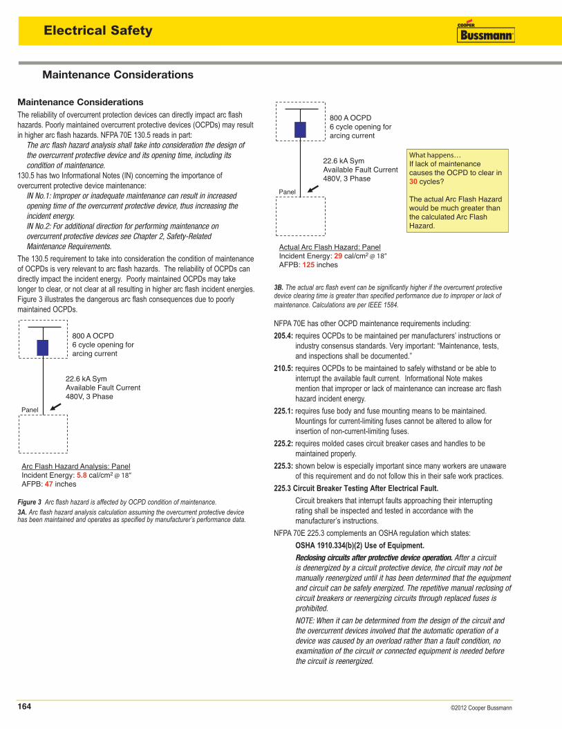
Arc Flash Analysis Equipment LabelingNEC 110.16 Arc Flash Hazard Warning does not require NFPA 70E arc flashhazard analysis information to be on the label. It is merely a label to warnpeople that there is an arc flash hazard but does not provide specific information on the level of arc flash hazard.
Label complying to NEC 110.16
NFPA 70E 130.5(C) requires specific information on the level of arc flash hazard to be marked on the equipment when an arc flash hazard analysis hasbeen performed. At a minimum the label must include these three items:
1. At least one of following
• Incident energy at the working distance
• Minimum arc rating of clothing
• Level of PPE required
• Required level of PPE (this may be to a specific company PPE safety program)
• Highest HRC for the equipment type
2. System voltage
3. Arc flash boundary
Additional information is often included on the label, such as the values determined by the shock approach boundaries
Label required by NFPA 70E 130.5(C) must provide specific values determined by an arc flash hazard analysis.
The last paragraph of 130.5 requires that the calculation method and data tosupport this information shall be documented. For instance, in both the incident energy method and HRC method the available short-circuit currentmust be determined in the process of the analysis. The method of calculatingthe short-circuit current and the results must be documented and retained.This information may be required for a future OSHA inspection/investigation.As well, if future system changes occur, this documentation will assist in determining whether the arc flash hazard results changed.
164 ©2012 Cooper Bussmann
Electrical Safety
Maintenance Considerations
Maintenance ConsiderationsThe reliability of overcurrent protection devices can directly impact arc flashhazards. Poorly maintained overcurrent protective devices (OCPDs) may resultin higher arc flash hazards. NFPA 70E 130.5 reads in part:
The arc flash hazard analysis shall take into consideration the design of the overcurrent protective device and its opening time, including its condition of maintenance.
130.5 has two Informational Notes (IN) concerning the importance of overcurrent protective device maintenance:
IN No.1: Improper or inadequate maintenance can result in increased opening time of the overcurrent protective device, thus increasing the incident energy.IN No.2: For additional direction for performing maintenance on overcurrent protective devices see Chapter 2, Safety-Related Maintenance Requirements.
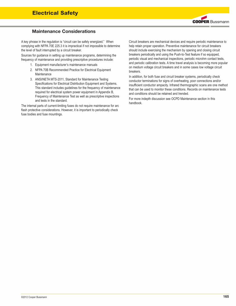
The 130.5 requirement to take into consideration the condition of maintenanceof OCPDs is very relevant to arc flash hazards. The reliability of OCPDs candirectly impact the incident energy. Poorly maintained OCPDs may takelonger to clear, or not clear at all resulting in higher arc flash incident energies.Figure 3 illustrates the dangerous arc flash consequences due to poorly maintained OCPDs.
Figure 3 Arc flash hazard is affected by OCPD condition of maintenance.3A. Arc flash hazard analysis calculation assuming the overcurrent protective devicehas been maintained and operates as specified by manufacturer’s performance data.
3B. The actual arc flash event can be significantly higher if the overcurrent protectivedevice clearing time is greater than specified performance due to improper or lack ofmaintenance. Calculations are per IEEE 1584.
NFPA 70E has other OCPD maintenance requirements including:
205.4: requires OCPDs to be maintained per manufacturers’ instructions or industry consensus standards. Very important: “Maintenance, tests, and inspections shall be documented.”
210.5: requires OCPDs to be maintained to safely withstand or be able to interrupt the available fault current. Informational Note makes mention that improper or lack of maintenance can increase arc flash hazard incident energy.
225.1: requires fuse body and fuse mounting means to be maintained. Mountings for current-limiting fuses cannot be altered to allow for insertion of non-current-limiting fuses.
225.2: requires molded cases circuit breaker cases and handles to be maintained properly.
225.3: shown below is especially important since many workers are unaware of this requirement and do not follow this in their safe work practices.
225.3 Circuit Breaker Testing After Electrical Fault.
Circuit breakers that interrupt faults approaching their interrupting rating shall be inspected and tested in accordance with the manufacturer’s instructions.
NFPA 70E 225.3 complements an OSHA regulation which states:
OSHA 1910.334(b)(2) Use of Equipment.
Reclosing circuits after protective device operation. After a circuit is deenergized by a circuit protective device, the circuit may not be manually reenergized until it has been determined that the equipment and circuit can be safely energized. The repetitive manual reclosing of circuit breakers or reenergizing circuits through replaced fuses is prohibited.
NOTE: When it can be determined from the design of the circuit and the overcurrent devices involved that the automatic operation of a device was caused by an overload rather than a fault condition, no examination of the circuit or connected equipment is needed before the circuit is reenergized.
22.6 kA Sym Available Fault Current 480V, 3 Phase
Arc Flash Hazard Analysis: Panel Incident Energy: 5.8 cal/cm2 @ 18” AFPB: 47 inches
Panel
800 A OCPD 6 cycle opening for arcing current
22.6 kA Sym Available Fault Current 480V, 3 Phase
Panel
800 A OCPD 6 cycle opening for arcing current
What happens… If lack of maintenance causes the OCPD to clear in 30 cycles? The actual Arc Flash Hazard would be much greater than the calculated Arc Flash Hazard.
Actual Arc Flash Hazard: Panel Incident Energy: 29 cal/cm2 @ 18” AFPB: 125 inches
165©2012 Cooper Bussmann
Maintenance Considerations
Electrical Safety
A key phrase in the regulation is “circuit can be safely energized.” When complying with NFPA 70E 225.3 it is impractical if not impossible to determinethe level of fault interrupted by a circuit breaker.
Sources for guidance in setting up maintenance programs, determining thefrequency of maintenance and providing prescriptive procedures include:
1. Equipment manufacturer’s maintenance manuals
2. NFPA 70B Recommended Practice for Electrical Equipment Maintenance
3. ANSI/NETA MTS-2011, Standard for Maintenance Testing Specifications for Electrical Distribution Equipment and Systems. This standard includes guidelines for the frequency of maintenance required for electrical system power equipment in Appendix B, Frequency of Maintenance Test as well as prescriptive inspections and tests in the standard.
The internal parts of current-limiting fuses do not require maintenance for arcflash protective considerations. However, it is important to periodically checkfuse bodies and fuse mountings.
Circuit breakers are mechanical devices and require periodic maintenance tohelp retain proper operation. Preventive maintenance for circuit breakersshould include exercising the mechanism by opening and closing circuit breakers periodically and using the Push-to-Test feature if so equipped, periodic visual and mechanical inspections, periodic microhm contact tests,and periodic calibration tests. A time travel analysis is becoming more popularon medium voltage circuit breakers and in some cases low voltage circuitbreakers.
In addition, for both fuse and circuit breaker systems, periodically check conductor terminations for signs of overheating, poor connections and/or insufficient conductor ampacity. Infrared thermographic scans are one methodthat can be used to monitor these conditions. Records on maintenance testsand conditions should be retained and trended.
For more indepth discussion see OCPD Maintenance section in this handbook.
Arc Flash Hazard Analysis
166 ©2012 Cooper Bussmann
Electrical Safety
Simple Method for Arc Flash Hazard AnalysisIn this section there are two examples of determining the arc flash hazard per 130.5(A) for the arc flash boundary and 130.5(B)(1) by the incidentenergy analysis method.
Various information about the system may be needed to complete this analysisbut the two pieces that are absolutely necessary are:
1. The available 3Ø bolted fault current.
2. The fuse or circuit breaker type and amp rating.
Consider the following one-line diagram and then follow the examples thattake the steps needed to conduct an arc flash hazard analysis.
The following information utilizes the simplified fuse formulas based uponIEEE 1584-2002 Guide for arc flash Hazard Analysis and shown in NFPA 70EAnnex D.7.6.
Steps necessary to conduct an arc flash hazard analysis when using Low-Peak fuses or circuit breakers and Table 1 and 1a: arc flash IncidentEnergy Calculator.
1. Determine the available bolted fault current on the lineside terminals of the equipment that will be worked upon.
2. Identify the amperage of the Low-Peak fuse or circuit breaker upstream that is protecting the panel where work is to be performed.
3. Consult the Low-Peak Fuse Incident Energy Calculator, Table 1 and 1a, nextpages, to determine the Incident Energy Exposure (I.E.) available.
4. Determine the AFB that will require PPE based upon the incident energy. This canalso be simplified by using the column for AFB in Table 1 and 1a.
5. Identify the minimum requirements for PPE when work is to be performed insideof the AFB by consulting the requirements found in NFPA 70E 130.7(C)(1) to(C)(16).
Example 1: Arc Flash Hazard Analysis using CooperBussmann Current-Limiting FusesThe following is a simple method when using certain Cooper Bussmann fuses;this method is based on actual data from arcing fault tests (and resulting simplified formulas shown in NFPA 70E Annex D.7.6 and 2002 IEEE 1584)with Cooper Bussmann current-limiting fuses. Using this simple method, thefirst thing that must be done is to determine the incident energy exposure.Cooper Bussmann has simplified this process when using LPS-RK_SP, LPJ_SP, TCF, LP-CC_ or KRP-C_SP Low-Peak fuses or JJS_ T-Tron fuses and FCF fuses. In some cases the results are conservative; see Note 6.
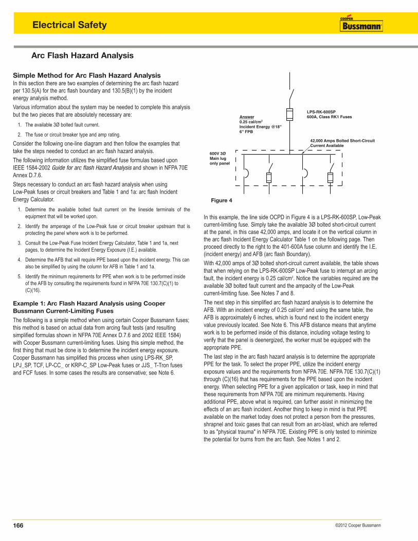
In this example, the line side OCPD in Figure 4 is a LPS-RK-600SP, Low-Peakcurrent-limiting fuse. Simply take the available 3Ø bolted short-circuit currentat the panel, in this case 42,000 amps, and locate it on the vertical column inthe arc flash Incident Energy Calculator Table 1 on the following page. Thenproceed directly to the right to the 401-600A fuse column and identify the I.E.(incident energy) and AFB (arc flash Boundary).
With 42,000 amps of 3Ø bolted short-circuit current available, the table showsthat when relying on the LPS-RK-600SP Low-Peak fuse to interrupt an arcingfault, the incident energy is 0.25 cal/cm2. Notice the variables required are theavailable 3Ø bolted fault current and the ampacity of the Low-Peak current-limiting fuse. See Notes 7 and 8.
The next step in this simplified arc flash hazard analysis is to determine theAFB. With an incident energy of 0.25 cal/cm2 and using the same table, theAFB is approximately 6 inches, which is found next to the incident energyvalue previously located. See Note 6. This AFB distance means that anytimework is to be performed inside of this distance, including voltage testing to verify that the panel is deenergized, the worker must be equipped with the appropriate PPE.
The last step in the arc flash hazard analysis is to determine the appropriatePPE for the task. To select the proper PPE, utilize the incident energy exposure values and the requirements from NFPA 70E. NFPA 70E 130.7(C)(1)through (C)(16) that has requirements for the PPE based upon the incidentenergy. When selecting PPE for a given application or task, keep in mind thatthese requirements from NFPA 70E are minimum requirements. Having additional PPE, above what is required, can further assist in minimizing theeffects of an arc flash incident. Another thing to keep in mind is that PPE available on the market today does not protect a person from the pressures,shrapnel and toxic gases that can result from an arc-blast, which are referredto as "physical trauma" in NFPA 70E. Existing PPE is only tested to minimizethe potential for burns from the arc flash. See Notes 1 and 2.
Figure 4
600V 3ØMain lugonly panel
42,000 Amps Bolted Short-Circuit Current Available
LPS-RK-600SP600A, Class RK1 FusesAnswer
0.25 cal/cm2
Incident Energy @18''6'' FPB
167©2012 Cooper Bussmann
Arc Flash Incident Energy Calculator
Arc Flash Hazard Analysis Tools on www.cooperbussmann.com/ArcFlashCalculatorCooper Bussmann continues to study this topic and develop more complete data and application tools.
Visit www.cooperbussmann.com for interactive arc flash calculators and the most current data.
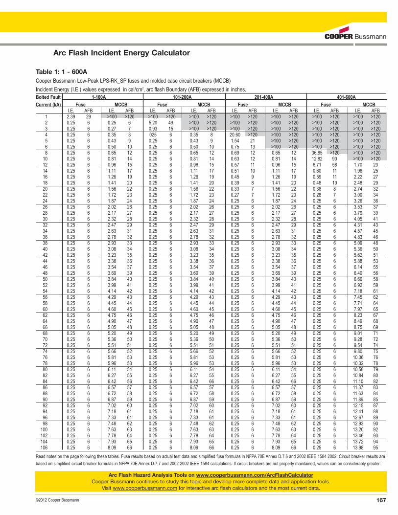
Table 1: 1 - 600ACooper Bussmann Low-Peak LPS-RK_SP fuses and molded case circuit breakers (MCCB)
Incident Energy (I.E.) values expressed in cal/cm2, arc flash Boundary (AFB) expressed in inches.Bolted Fault 1-100A 101-200A 201-400A 401-600A
Current (kA) Fuse MCCB Fuse MCCB Fuse MCCB Fuse MCCBI.E. AFB I.E. AFB I.E. AFB I.E. AFB I.E. AFB I.E. AFB I.E. AFB I.E. AFB
1 2.39 29 >100 >120 >100 >120 >100 >120 >100 >120 >100 >120 >100 >120 >100 >1202 0.25 6 0.25 6 5.20 49 >100 >120 >100 >120 >100 >120 >100 >120 >100 >1203 0.25 6 0.27 7 0.93 15 >100 >120 >100 >120 >100 >120 >100 >120 >100 >1204 0.25 6 0.35 8 025 6 0.35 8 20.60 >120 >100 >120 >100 >120 >100 >1205 0.25 6 0.43 9 0.25 6 0.43 9 1.54 21 >100 >120 >100 >120 >100 >1206 0.25 6 0.50 10 0.25 6 0.50 10 0.75 13 >100 >120 >100 >120 >100 >1208 0.25 6 0.65 12 0.25 6 0.65 12 0.69 12 0.65 12 36.85 >120 >100 >12010 0.25 6 0.81 14 0.25 6 0.81 14 0.63 12 0.81 14 12.82 90 >100 >12012 0.25 6 0.96 15 0.25 6 0.96 15 0.57 11 0.96 15 6.71 58 1.70 2314 0.25 6 1.11 17 0.25 6 1.11 17 0.51 10 1.11 17 0.60 11 1.96 2516 0.25 6 1.26 19 0.25 6 1.26 19 0.45 9 1.26 19 0.59 11 2.22 2718 0.25 6 1.41 20 0.25 6 1.41 20 0.39 8 1.41 20 0.48 10 2.48 2920 0.25 6 1.56 22 0.25 6 1.56 22 0.33 7 1.56 22 0.38 8 2.74 3222 0.25 6 1.72 23 0.25 6 1.72 23 0.27 7 1.72 23 0.28 7 3.00 3424 0.25 6 1.87 24 0.25 6 1.87 24 0.25 6 1.87 24 0.25 6 3.26 3626 0.25 6 2.02 26 0.25 6 2.02 26 0.25 6 2.02 26 0.25 6 3.53 3728 0.25 6 2.17 27 0.25 6 2.17 27 0.25 6 2.17 27 0.25 6 3.79 3930 0.25 6 2.32 28 0.25 6 2.32 28 0.25 6 2.32 28 0.25 6 4.05 4132 0.25 6 2.47 29 0.25 6 2.47 29 0.25 6 2.47 29 0.25 6 4.31 4334 0.25 6 2.63 31 0.25 6 2.63 31 0.25 6 2.63 31 0.25 6 4.57 4536 0.25 6 2.78 32 0.25 6 2.78 32 0.25 6 2.78 32 0.25 6 4.83 4638 0.25 6 2.93 33 0.25 6 2.93 33 0.25 6 2.93 33 0.25 6 5.09 4840 0.25 6 3.08 34 0.25 6 3.08 34 0.25 6 3.08 34 0.25 6 5.36 5042 0.25 6 3.23 35 0.25 6 3.23 35 0.25 6 3.23 35 0.25 6 5.62 5144 0.25 6 3.38 36 0.25 6 3.38 36 0.25 6 3.38 36 0.25 6 5.88 5346 0.25 6 3.54 37 0.25 6 3.54 37 0.25 6 3.54 37 0.25 6 6.14 5548 0.25 6 3.69 39 0.25 6 3.69 39 0.25 6 3.69 39 0.25 6 6.40 5650 0.25 6 3.84 40 0.25 6 3.84 40 0.25 6 3.84 40 0.25 6 6.66 5852 0.25 6 3.99 41 0.25 6 3.99 41 0.25 6 3.99 41 0.25 6 6.92 5954 0.25 6 4.14 42 0.25 6 4.14 42 0.25 6 4.14 42 0.25 6 7.18 6156 0.25 6 4.29 43 0.25 6 4.29 43 0.25 6 4.29 43 0.25 6 7.45 6258 0.25 6 4.45 44 0.25 6 4.45 44 0.25 6 4.45 44 0.25 6 7.71 6460 0.25 6 4.60 45 0.25 6 4.60 45 0.25 6 4.60 45 0.25 6 7.97 6562 0.25 6 4.75 46 0.25 6 4.75 46 0.25 6 4.75 46 0.25 6 8.23 6764 0.25 6 4.90 47 0.25 6 4.90 47 0.25 6 4.90 47 0.25 6 8.49 6866 0.25 6 5.05 48 0.25 6 5.05 48 0.25 6 5.05 48 0.25 6 8.75 6968 0.25 6 5.20 49 0.25 6 5.20 49 0.25 6 5.20 49 0.25 6 9.01 7170 0.25 6 5.36 50 0.25 6 5.36 50 0.25 6 5.36 50 0.25 6 9.28 7272 0.25 6 5.51 51 0.25 6 5.51 51 0.25 6 5.51 51 0.25 6 9.54 7474 0.25 6 5.66 52 0.25 6 5.66 52 0.25 6 5.66 52 0.25 6 9.80 7576 0.25 6 5.81 53 0.25 6 5.81 53 0.25 6 5.81 53 0.25 6 10.06 7678 0.25 6 5.96 53 0.25 6 5.96 53 0.25 6 5.96 53 0.25 6 10.32 7880 0.25 6 6.11 54 0.25 6 6.11 54 0.25 6 6.11 54 0.25 6 10.58 7982 0.25 6 6.27 55 0.25 6 6.27 55 0.25 6 6.27 55 0.25 6 10.84 8084 0.25 6 6.42 56 0.25 6 6.42 66 0.25 6 6.42 66 0.25 6 11.10 8286 0.25 6 6.57 57 0.25 6 6.57 57 0.25 6 6.57 57 0.25 6 11.37 8388 0.25 6 6.72 58 0.25 6 6.72 58 0.25 6 6.72 58 0.25 6 11.63 8490 0.25 6 6.87 59 0.25 6 6.87 59 0.25 6 6.87 59 0.25 6 11.89 8592 0.25 6 7.02 60 0.25 6 7.02 60 0.25 6 7.02 60 0.25 6 12.15 8794 0.25 6 7.18 61 0.25 6 7.18 61 0.25 6 7.18 61 0.25 6 12.41 8896 0.25 6 7.33 61 0.25 6 7.33 61 0.25 6 7.33 61 0.25 6 12.67 8998 0.25 6 7.48 62 0.25 6 7.48 62 0.25 6 7.48 62 0.25 6 12.93 90100 0.25 6 7.63 63 0.25 6 7.63 63 0.25 6 7.63 63 0.25 6 13.20 92102 0.25 6 7.78 64 0.25 6 7.78 64 0.25 6 7.78 64 0.25 6 13.46 93104 0.25 6 7.93 65 0.25 6 7.93 65 0.25 6 7.93 65 0.25 6 13.72 94106 0.25 6 8.09 66 0.25 6 8.09 66 0.25 6 8.09 66 0.25 6 13.98 95
Read notes on the page following these tables. Fuse results based on actual test data and simplified fuse formulas in NFPA 70E Annex D.7.6 and 2002 IEEE 1584 2002. Circuit breaker results are
based on simplified circuit breaker formulas in NFPA 70E Annex D.7.7 and 2002 2002 IEEE 1584 calculations. If circuit breakers are not properly maintained, values can be considerably greater.
Electrical Safety
Arc Flash Incident Energy Calculator
168 ©2012 Cooper Bussmann
Electrical Safety
Arc Flash Hazard Analysis Tools on www.cooperbussmann.com/ArcFlashCalculatorCooper Bussmann continues to study this topic and develop more complete data and application tools.
Visit www.cooperbussmann.com for interactive arc flash calculators and the most current data.
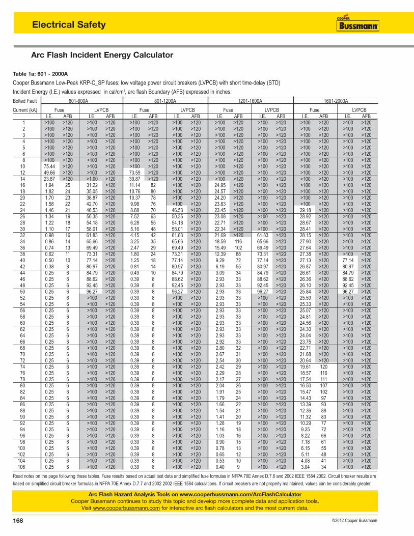
Table 1a: 601 - 2000ACooper Bussmann Low-Peak KRP-C_SP fuses; low voltage power circuit breakers (LVPCB) with short time-delay (STD)
Incident Energy (I.E.) values expressed in cal/cm2, arc flash Boundary (AFB) expressed in inches.
Bolted Fault 601-800A 801-1200A 1201-1600A 1601-2000A
Current (kA) Fuse LVPCB Fuse LVPCB Fuse LVPCB Fuse LVPCBI.E. AFB I.E. AFB I.E. AFB I.E. AFB I.E. AFB I.E. AFB I.E. AFB I.E. AFB
1 >100 >120 >100 >120 >100 >120 >100 >120 >100 >120 >100 >120 >100 >120 >100 >1202 >100 >120 >100 >120 >100 >120 >100 >120 >100 >120 >100 >120 >100 >120 >100 >1203 >100 >120 >100 >120 >100 >120 >100 >120 >100 >120 >100 >120 >100 >120 >100 >1204 >100 >120 >100 >120 >100 >120 >100 >120 >100 >120 >100 >120 >100 >120 >100 >1205 >100 >120 >100 >120 >100 >120 >100 >120 >100 >120 >100 >120 >100 >120 >100 >1206 >100 >120 >100 >120 >100 >120 >100 >120 >100 >120 >100 >120 >100 >120 >100 >1208 >100 >120 >100 >120 >100 >120 >100 >120 >100 >120 >100 >120 >100 >120 >100 >12010 75.44 >120 >100 >120 >100 >120 >100 >120 >100 >120 >100 >120 >100 >120 >100 >12012 49.66 >120 >100 >120 73.59 >120 >100 >120 >100 >120 >100 >120 >100 >120 >100 >12014 23.87 >120 >1.00 >120 39.87 >120 >100 >120 >100 >120 >100 >120 >100 >120 >100 >12016 1.94 25 31.22 >120 11.14 82 >100 >120 24.95 >120 >100 >120 >100 >120 >100 >12018 1.82 24 35.05 >120 10.76 80 >100 >120 24.57 >120 >100 >120 >100 >120 >100 >12020 1.70 23 38.87 >120 10.37 78 >100 >120 24.20 >120 >100 >120 >100 >120 >100 >12022 1.58 22 42.70 >120 9.98 76 >100 >120 23.83 >120 >100 >120 >100 >120 >100 >12024 1.46 21 46.53 >120 8.88 70 46.53 >120 23.45 >120 >100 >120 29.18 >120 >100 >12026 1.34 19 50.35 >120 7.52 63 50.35 >120 23.08 >120 >100 >120 28.92 >120 >100 >12028 1.22 18 54.18 >120 6.28 55 54.18 >120 22.71 >120 >100 >120 28.67 >120 >100 >12030 1.10 17 58.01 >120 5.16 48 58.01 >120 22.34 >120 >100 >120 28.41 >120 >100 >12032 0.98 16 61.83 >120 4.15 42 61.83 >120 21.69 >120 61.83 >120 28.15 >120 >100 >12034 0.86 14 65.66 >120 3.25 35 65.66 >120 18.59 116 65.66 >120 27.90 >120 >100 >12036 0.74 13 69.49 >120 2.47 29 69.49 >120 15.49 102 69.49 >120 27.64 >120 >100 >12038 0.62 11 73.31 >120 1.80 24 73.31 >120 12.39 88 73.31 >120 27.38 >120 >100 >12040 0.50 10 77.14 >120 1.25 18 77.14 >120 9.29 72 77.14 >120 27.13 >120 77.14 >12042 0.38 8 80.97 >120 0.81 14 80.97 >120 6.19 55 80.97 >120 26.87 >120 80.97 >12044 0.25 6 84.79 >120 0.49 10 84.79 >120 3.09 34 84.79 >120 26.61 >120 84.79 >12046 0.25 6 88.62 >120 0.39 8 88.62 >120 2.93 33 88.62 >120 26.36 >120 88.62 >12048 0.25 6 92.45 >120 0.39 8 92.45 >120 2.93 33 92.45 >120 26.10 >120 92.45 >12050 0.25 6 96.27 >120 0.39 8 96.27 >120 2.93 33 96.27 >120 25.84 >120 96.27 >12052 0.25 6 >100 >120 0.39 8 >100 >120 2.93 33 >100 >120 25.59 >120 >100 >12054 0.25 6 >100 >120 0.39 8 >100 >120 2.93 33 >100 >120 25.33 >120 >100 >12056 0.25 6 >100 >120 0.39 8 >100 >120 2.93 33 >100 >120 25.07 >120 >100 >12058 0.25 6 >100 >120 0.39 8 >100 >120 2.93 33 >100 >120 24.81 >120 >100 >12060 0.25 6 >100 >120 0.39 8 >100 >120 2.93 33 >100 >120 24.56 >120 >100 >12062 0.25 6 >100 >120 0.39 8 >100 >120 2.93 33 >100 >120 24.30 >120 >100 >12064 0.25 6 >100 >120 0.39 8 >100 >120 2.93 33 >100 >120 24.04 >120 >100 >12066 0.25 6 >100 >120 0.39 8 >100 >120 2.92 33 >100 >120 23.75 >120 >100 >12068 0.25 6 >100 >120 0.39 8 >100 >120 2.80 32 >100 >120 22.71 >120 >100 >12070 0.25 6 >100 >120 0.39 8 >100 >120 2.67 31 >100 >120 21.68 >120 >100 >12072 0.25 6 >100 >120 0.39 8 >100 >120 2.54 30 >100 >120 20.64 >120 >100 >12074 0.25 6 >100 >120 0.39 8 >100 >120 2.42 29 >100 >120 19.61 120 >100 >12076 0.25 6 >100 >120 0.39 8 >100 >120 2.29 28 >100 >120 18.57 116 >100 >12078 0.25 6 >100 >120 0.39 8 >100 >120 2.17 27 >100 >120 17.54 111 >100 >12080 0.25 6 >100 >120 0.39 8 >100 >120 2.04 26 >100 >120 16.50 107 >100 >12082 0.25 6 >100 >120 0.39 8 >100 >120 1.91 25 >100 >120 15.47 102 >100 >12084 0.25 6 >100 >120 0.39 8 >100 >120 1.79 24 >100 >120 14.43 97 >100 >12086 0.25 6 >100 >120 0.39 8 >100 >120 1.66 22 >100 >120 13.39 93 >100 >12088 0.25 6 >100 >120 0.39 8 >100 >120 1.54 21 >100 >120 12.36 88 >100 >12090 0.25 6 >100 >120 0.39 8 >100 >120 1.41 20 >100 >120 11.32 83 >100 >12092 0.25 6 >100 >120 0.39 8 >100 >120 1.28 19 >100 >120 10.29 77 >100 >12094 0.25 6 >100 >120 0.39 8 >100 >120 1.16 18 >100 >120 9.25 72 >100 >12096 0.25 6 >100 >120 0.39 8 >100 >120 1.03 16 >100 >120 8.22 66 >100 >12098 0.25 6 >100 >120 0.39 8 >100 >120 0.90 15 >100 >120 7.18 61 >100 >120100 0.25 6 >100 >120 0.39 8 >100 >120 0.78 13 >100 >120 6.15 55 >100 >120102 0.25 6 >100 >120 0.39 8 >100 >120 0.65 12 >100 >120 5.11 48 >100 >120104 0.25 6 >100 >120 0.39 8 >100 >120 0.53 10 >100 >120 4.08 41 >100 >120106 0.25 6 >100 >120 0.39 8 >100 >120 0.40 9 >100 >120 3.04 34 >100 >120
Read notes on the page following these tables. Fuse results based on actual test data and simplified fuse formulas in NFPA 70E Annex D.7.6 and 2002 IEEE 1584 2002. Circuit breaker results are
based on simplified circuit breaker formulas in NFPA 70E Annex D.7.7 and 2002 2002 IEEE 1584 calculations. If circuit breakers are not properly maintained, values can be considerably greater.
169©2012 Cooper Bussmann
Arc Flash Incident Energy Calculator
Notes for Arc Flash Hazard Analysis Table 1 and 1a
Steps necessary to conduct a Flash Hazard Analysis.
1. Determine the available bolted fault current on the line side terminals of theequipment that will be worked upon.
2. Identify the amperage of the upstream Low-Peak fuse or circuit breaker thatis protecting the equipment where work is to be performed.
3. Consult the table to determine the incident energy exposure and the arc flash Boundary (AFB).
4. Identify the minimum requirements for PPE when work is to be performedinside of the AFB by consulting the requirements found in NFPA 70E.
General Notes for fuses and circuit breakers:Note 1: First and foremost, this information is not to be used as a recommendation to work on energized equipment. This information is to helpassist in determining the PPE to help safeguard a worker from the burns thatcan be sustained from an arc flash incident. This information does not takeinto account the effects of pressure, shrapnel, molten metal spray or the toxicvapor resulting from an arc-fault. This information does not address the maintenance conditions of the overcurrent protective device.
Note 2: This data is based upon the simplified fuse and circuit breaker formulas in NFPA 70E Annex D.7.6 and D.7.7 and 2002 2002 IEEE 1584Guide for arc flash Hazard Analysis. These methods were created so that the PPEselected from the calculated incident energy would be adequate for 98% of arcflash incidents. In up to 2% of incidents, second-degree burns to the body andtorso could result. This was based upon PPE with standard arc ratings of 1.2,8, 25, 40 and 100 cal/cm2. PPE with intermediate ATPV values can be utilized, but at the next lower standard ATPV rating. NFPA 70E Annex D.7does not recognize 100 cal/cm2, instead a fine print note is added to recommend greater emphasis than normal to de-energize equipment when theincident energy exceeds 40 cal/cm2.
Note 3: PPE must be utilized any time work is to be performed on equipmentthat is not placed in an electrically safe work condition. Voltage testing, whilecompleting the lockout/tagout procedure (putting the equipment in an electrically safe work condition), is considered as working on energized partsper OSHA 1910.333(b).
Note 4: The data is based on 32mm (1 1⁄4˝) electrode spacing, 600V 3Øungrounded system, and 20˝ x 20˝ x 20˝ box. The incident energy is based ona working distance of 18 inches, and the AFB is based on 1.2 cal/cm2
(threshold for a second-degree “just curable” burn).
Note 5: The data is based upon tests that were conducted at various fault currents for each Cooper Bussmann Low-Peak KRP-C_SP and LPS-RK_SPfuse indicated in the charts. These tests were used to develop the formulas asshown in NFPA 70E Annex D.7.6 and 2002 IEEE 1584 2002. Actual resultsfrom incidents could be different for a number of reasons, including different (1)system voltage, (2) short-circuit power factor, (3) distance from the arc, (4) arcgap, (5) enclosure size, (6) fuse manufacturer, (7) fuse class, (8) orientation ofthe worker and (9) grounding scheme. 100A LPS-RK_SP fuses were thesmallest fuses tested. Data for the fuses smaller than that is based upon the100A data. arc flash values for actual 30 and 60A fuses would be considerablyless than 100A fuses. However, it does not matter since the values for the100A fuses are already so low.
Note 6: The fuse incident energy values were chosen not to go below0.25cal/cm2 even though many actual values were below 0.25cal/cm2. Thiswas chosen to keep from encouraging work on energized equipment withoutPPE because of a low AFB.
Note 7: This arc flash Incident Energy Calculator Table can also be used forLPJ_SP, TCF, FCF, JJS, and LP-CC fuses to determine the incident energyavailable and AFB.
Note 8: These values from fuse tests and calculations for circuit breakers takeinto account the translation from available 3-phase bolted fault current to thearcing fault current.
Note 9: To determine the AFB and incident energy for applications with otherfuses, use the basic equations in 2002 2002 IEEE 1584 or NFPA 70E AnnexD.7.
Note 10: The circuit breaker information comes from the simplified circuit breaker equations in 2002 2002 IEEE 1584 and NFPA 70E Annex D.7.7 thatare based upon how circuit breakers operate.
Note 11: Where the arcing current is less than the instantaneous trip setting ofthe circuit breaker or current-limiting range of the fuse when calculated perNFPA 70E Annex D.7.6 or D.7.7 and 2002 IEEE 1584 2002. The value for incident energy is given as >100cal/cm2.
Note 12: The data for circuit breakers up to 400A is based on Molded CaseCircuit Breakers (MCCB) with instantaneous trip, for 401-600A it is based onMCCBs with electronic trip units, and the data for circuit breakers from 601 upto 2000A is based on Low Voltage Power Circuit Breakers (LVPCB) with shorttime-delay (STD). Per the simplified circuit breaker formulas in NFPA 70EAnnex D.7.7 and 2002 2002 IEEE 1584 the STD setting is assumed to be setat maximum.
Note 13: The data for circuit breakers is based upon devices being properlymaintained in accordance with manufacturer’s instructions and industry standards. Devices that are not properly tested and maintained may havelonger clearing times resulting in higher incident energies.
Electrical Safety
Arc Flash Hazard Analysis
170 ©2012 Cooper Bussmann
Electrical Safety
Example 2: Arc Flash Hazard Analysis Using CircuitBreakers.**WARNING** If a Circuit Breaker has not been exercised, tested, andmaintained per manufacturers instructions or industry standards (NFPA 70Bor ANSI/ANSI MTS-11), then a longer clearing time may occur, resulting in a higher incident energy calculation. Consult www.cooperbussmann.com, or www.netaworld.org for more information ortechnical papers on testing and maintenance and/or consequences topotential arc flash hazard.
The following is a simplified method using Table 1 as done in Example 1.Instead of using LPS-RK-600SP, 600A, current-limiting fuse, we will use a600A Molded Case Circuit Breaker.
With the same 3Ø available short-circuit current as in example 1, 42,000amps, locate this on the vertical column (Bolted Fault Current kA) of Table 1.Then proceed directly to the right over to the 401-600A MCCB Column. Thenrecord the I.E. (Incident Energy) which should be 5.62 cal/cm2. Also, recordthe value for the AFB (Arc Flash Boundary) which is 51 inches.
The last step in the arc flash hazard analysis is to determine the appropriatePPE for the task.
If the circuit breaker in question is a Low Voltage Power Circuit Breaker(LVPCB) with short time-delay feature (no instantaneous trip), the incidentenergy calculation will increase. For example, with a short time-delay featureset at 30 cycles the incident energy at this available fault current could be ashigh as 80.97 (see value in Table 1a with a bolted fault current of 42kA for601-800A LVPCB) cal/cm2 at 18 inches from the arc fault source.
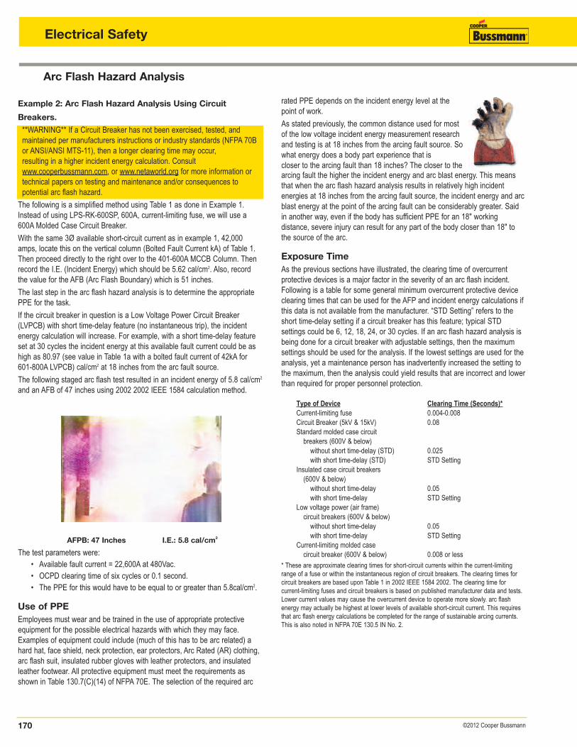
The following staged arc flash test resulted in an incident energy of 5.8 cal/cm2
and an AFB of 47 inches using 2002 2002 IEEE 1584 calculation method.
arcing fault the higher the incident energy and arc blast energy. This meansthat when the arc flash hazard analysis results in relatively high incident energies at 18 inches from the arcing fault source, the incident energy and arcblast energy at the point of the arcing fault can be considerably greater. Saidin another way, even if the body has sufficient PPE for an 18" working distance, severe injury can result for any part of the body closer than 18" tothe source of the arc.
Exposure TimeAs the previous sections have illustrated, the clearing time of overcurrent protective devices is a major factor in the severity of an arc flash incident.Following is a table for some general minimum overcurrent protective device clearing times that can be used for the AFP and incident energy calculations ifthis data is not available from the manufacturer. “STD Setting” refers to theshort time-delay setting if a circuit breaker has this feature; typical STD settings could be 6, 12, 18, 24, or 30 cycles. If an arc flash hazard analysis isbeing done for a circuit breaker with adjustable settings, then the maximumsettings should be used for the analysis. If the lowest settings are used for theanalysis, yet a maintenance person has inadvertently increased the setting tothe maximum, then the analysis could yield results that are incorrect and lowerthan required for proper personnel protection.
Type of Device Clearing Time (Seconds)*Current-limiting fuse 0.004-0.008Circuit Breaker (5kV & 15kV) 0.08Standard molded case circuitbreakers (600V & below)without short time-delay (STD) 0.025with short time-delay (STD) STD Setting
Insulated case circuit breakers(600V & below)without short time-delay 0.05with short time-delay STD Setting
Low voltage power (air frame)circuit breakers (600V & below)without short time-delay 0.05with short time-delay STD Setting
Current-limiting molded casecircuit breaker (600V & below) 0.008 or less
* These are approximate clearing times for short-circuit currents within the current-limitingrange of a fuse or within the instantaneous region of circuit breakers. The clearing times forcircuit breakers are based upon Table 1 in 2002 IEEE 1584 2002. The clearing time for current-limiting fuses and circuit breakers is based on published manufacturer data and tests.Lower current values may cause the overcurrent device to operate more slowly. arc flashenergy may actually be highest at lower levels of available short-circuit current. This requiresthat arc flash energy calculations be completed for the range of sustainable arcing currents.This is also noted in NFPA 70E 130.5 IN No. 2.
AFPB: 47 Inches I.E.: 5.8 cal/cm2
The test parameters were:• Available fault current = 22,600A at 480Vac.• OCPD clearing time of six cycles or 0.1 second.• The PPE for this would have to be equal to or greater than 5.8cal/cm2.
Use of PPEEmployees must wear and be trained in the use of appropriate protectiveequipment for the possible electrical hazards with which they may face.Examples of equipment could include (much of this has to be arc related) ahard hat, face shield, neck protection, ear protectors, Arc Rated (AR) clothing,arc flash suit, insulated rubber gloves with leather protectors, and insulatedleather footwear. All protective equipment must meet the requirements asshown in Table 130.7(C)(14) of NFPA 70E. The selection of the required arc
rated PPE depends on the incident energy level at thepoint of work.
As stated previously, the common distance used for mostof the low voltage incident energy measurement researchand testing is at 18 inches from the arcing fault source. Sowhat energy does a body part experience that is closer to the arcing fault than 18 inches? The closer to the
171©2012 Cooper Bussmann
Arc Flash Hazard Analysis
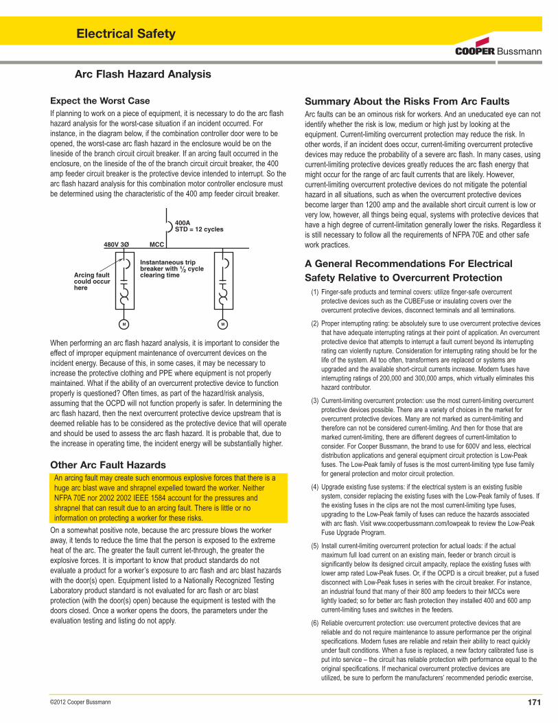
Expect the Worst CaseIf planning to work on a piece of equipment, it is necessary to do the arc flashhazard analysis for the worst-case situation if an incident occurred. Forinstance, in the diagram below, if the combination controller door were to beopened, the worst-case arc flash hazard in the enclosure would be on the lineside of the branch circuit circuit breaker. If an arcing fault occurred in theenclosure, on the lineside of the of the branch circuit circuit breaker, the 400amp feeder circuit breaker is the protective device intended to interrupt. So thearc flash hazard analysis for this combination motor controller enclosure mustbe determined using the characteristic of the 400 amp feeder circuit breaker.
Summary About the Risks From Arc FaultsArc faults can be an ominous risk for workers. And an uneducated eye can notidentify whether the risk is low, medium or high just by looking at the equipment. Current-limiting overcurrent protection may reduce the risk. Inother words, if an incident does occur, current-limiting overcurrent protectivedevices may reduce the probability of a severe arc flash. In many cases, usingcurrent-limiting protective devices greatly reduces the arc flash energy thatmight occur for the range of arc fault currents that are likely. However, current-limiting overcurrent protective devices do not mitigate the potentialhazard in all situations, such as when the overcurrent protective devicesbecome larger than 1200 amp and the available short circuit current is low orvery low, however, all things being equal, systems with protective devices thathave a high degree of current-limitation generally lower the risks. Regardless itis still necessary to follow all the requirements of NFPA 70E and other safework practices.
A General Recommendations For ElectricalSafety Relative to Overcurrent Protection(1) Finger-safe products and terminal covers: utilize finger-safe overcurrent
protective devices such as the CUBEFuse or insulating covers over the overcurrent protective devices, disconnect terminals and all terminations.
(2) Proper interrupting rating: be absolutely sure to use overcurrent protective devicesthat have adequate interrupting ratings at their point of application. An overcurrentprotective device that attempts to interrupt a fault current beyond its interruptingrating can violently rupture. Consideration for interrupting rating should be for thelife of the system. All too often, transformers are replaced or systems are upgraded and the available short-circuit currents increase. Modern fuses haveinterrupting ratings of 200,000 and 300,000 amps, which virtually eliminates thishazard contributor.
(3) Current-limiting overcurrent protection: use the most current-limiting overcurrentprotective devices possible. There are a variety of choices in the market for overcurrent protective devices. Many are not marked as current-limiting and therefore can not be considered current-limiting. And then for those that aremarked current-limiting, there are different degrees of current-limitation to consider. For Cooper Bussmann, the brand to use for 600V and less, electricaldistribution applications and general equipment circuit protection is Low-Peakfuses. The Low-Peak family of fuses is the most current-limiting type fuse familyfor general protection and motor circuit protection.
(4) Upgrade existing fuse systems: if the electrical system is an existing fusible system, consider replacing the existing fuses with the Low-Peak family of fuses. Ifthe existing fuses in the clips are not the most current-limiting type fuses, upgrading to the Low-Peak family of fuses can reduce the hazards associatedwith arc flash. Visit www.cooperbussmann.com/lowpeak to review the Low-PeakFuse Upgrade Program.
(5) Install current-limiting overcurrent protection for actual loads: if the actual maximum full load current on an existing main, feeder or branch circuit is significantly below its designed circuit ampacity, replace the existing fuses with lower amp rated Low-Peak fuses. Or, if the OCPD is a circuit breaker, put a fuseddisconnect with Low-Peak fuses in series with the circuit breaker. For instance, an industrial found that many of their 800 amp feeders to their MCCs were lightly loaded; so for better arc flash protection they installed 400 and 600 ampcurrent-limiting fuses and switches in the feeders.
(6) Reliable overcurrent protection: use overcurrent protective devices that are reliable and do not require maintenance to assure performance per the originalspecifications. Modern fuses are reliable and retain their ability to react quicklyunder fault conditions. When a fuse is replaced, a new factory calibrated fuse isput into service – the circuit has reliable protection with performance equal to theoriginal specifications. If mechanical overcurrent protective devices are utilized, be sure to perform the manufacturers’ recommended periodic exercise,
400ASTD = 12 cycles
480V 3O MCC
M M
Arcing fault could occur here
Instantaneous trip breaker with ⁄Ω™ cycle clearing time
When performing an arc flash hazard analysis, it is important to consider theeffect of improper equipment maintenance of overcurrent devices on the incident energy. Because of this, in some cases, it may be necessary toincrease the protective clothing and PPE where equipment is not properlymaintained. What if the ability of an overcurrent protective device to functionproperly is questioned? Often times, as part of the hazard/risk analysis,assuming that the OCPD will not function properly is safer. In determining thearc flash hazard, then the next overcurrent protective device upstream that isdeemed reliable has to be considered as the protective device that will operateand should be used to assess the arc flash hazard. It is probable that, due tothe increase in operating time, the incident energy will be substantially higher.
Other Arc Fault HazardsAn arcing fault may create such enormous explosive forces that there is ahuge arc blast wave and shrapnel expelled toward the worker. NeitherNFPA 70E nor 2002 2002 IEEE 1584 account for the pressures and shrapnel that can result due to an arcing fault. There is little or no information on protecting a worker for these risks.
On a somewhat positive note, because the arc pressure blows the workeraway, it tends to reduce the time that the person is exposed to the extremeheat of the arc. The greater the fault current let-through, the greater the explosive forces. It is important to know that product standards do not evaluate a product for a worker’s exposure to arc flash and arc blast hazardswith the door(s) open. Equipment listed to a Nationally Recognized TestingLaboratory product standard is not evaluated for arc flash or arc blast protection (with the door(s) open) because the equipment is tested with thedoors closed. Once a worker opens the doors, the parameters under the evaluation testing and listing do not apply.
Electrical Safety
Arc Flash Protection Marking
172 ©2012 Cooper Bussmann
Electrical Safety
maintenance, testing and possible replacement. When an arc fault or overcurrent occurs, the overcurrent protective device must be able to operate as intended.Thus, for mechanical overcurrent protective devices, this may require testing,maintenance, and possible replacement before resetting the device after a faultinterruption.
(7) Reduce feeder size in design phase: Reducing the size of large feeders can greatly reduce incident energy, especially for feeders 1600A and larger.
(8) Within sight motor disconnects: install HP rated disconnects (with permanentlyinstalled lockout provision) within sight and within 50 feet of every motor or driven machine. This measure fosters safer work practices and can be used for anemergency disconnect if there is an incident.
(9) Where “power” or “air frame” circuit breakers are utilized without an instantaneous trip, 240.87 requires some means to reduce the arc flash hazard. Potential solutions include, but are not limited to: (1) arc flash reducingmaintenance switches, differential relaying, and zone selective interlocking. SeeLow Voltage Power Circuit Breakers (LVPCB) with short time-delay in the sectionon Selective Coordination – Circuit Breakers.


![Electrical Safety Presentation [NFPA 70E]](https://img.pdfslide.us/doc/110x75/552f7e274a79595f328b45c8/electrical-safety-presentation-nfpa-70e.jpg)