Embed Size (px)
Citation preview
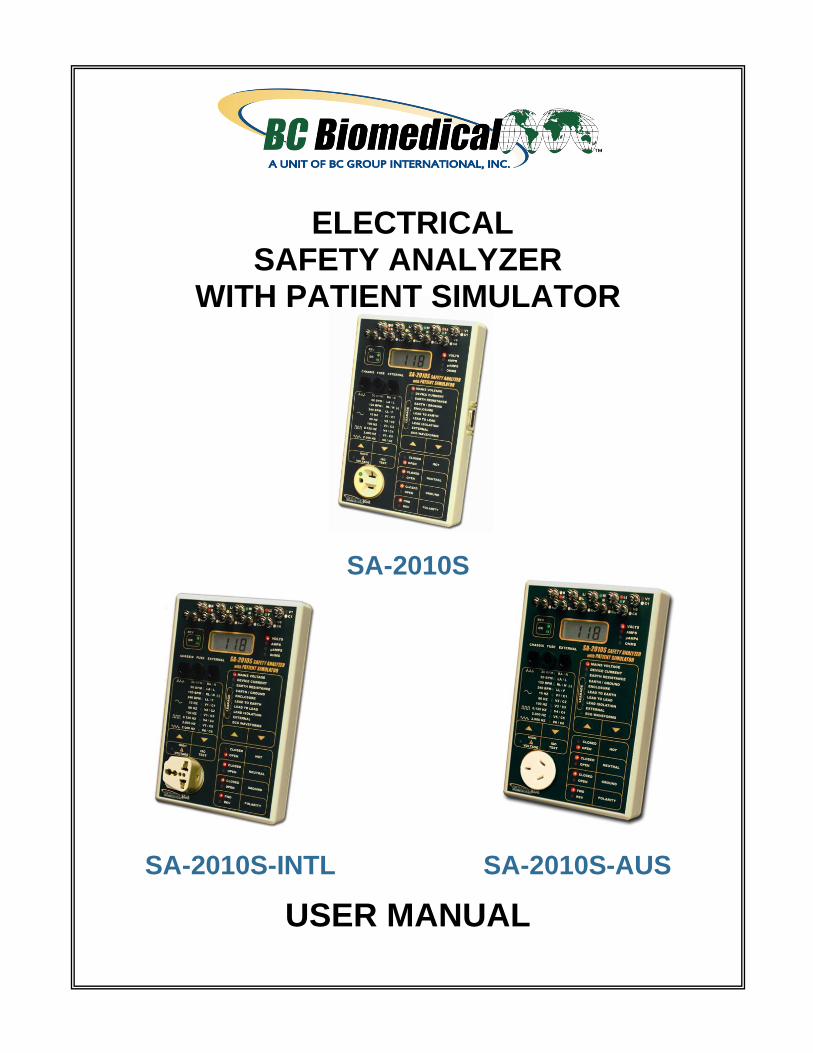
ELECTRICAL SAFETY ANALYZER
WITH PATIENT SIMULATOR
SA-2010S
SA-2010S-INTL SA-2010S-AUS
USER MANUAL

i
WARNINGS, CAUTIONS, NOTICES ............................................................................ ii
DESCRIPTION ............................................................................................................. 1
LAYOUT ....................................................................................................................... 4
TESTING ...................................................................................................................... 10
PATIENT SIMULATOR ................................................................................................ 15
COMMUNICATION PROTOCOL ................................................................................ 16
MANUAL REVISIONS .................................................................................................. 19
LIMITED WARRANTY .................................................................................................. 19
SPECIFICATIONS ....................................................................................................... 20
NOTES ......................................................................................................................... 24
BC BIOMEDICAL SA-2010S SERIES
TABLE OF CONTENTS
This User Manual covers the following units:
SA-2010S & SA-2010S-R
SA-2010S-INTL & SA-2010S-INTL-R
SA-2010S-AUS & SA-2010S-AUS-R
ii
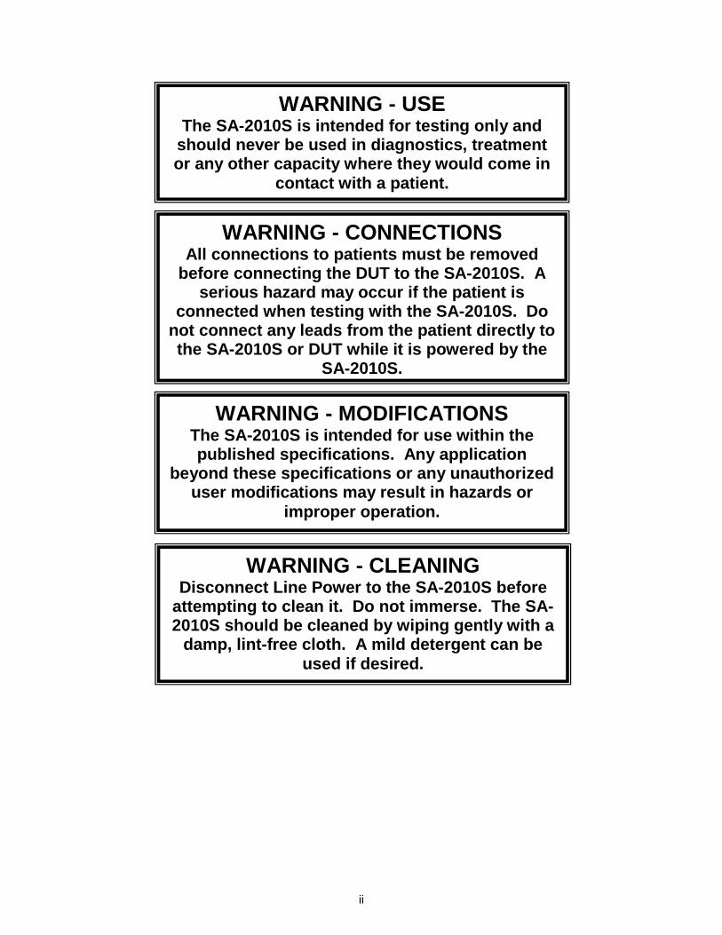
WARNING - USE
The SA-2010S is intended for testing only and should never be used in diagnostics, treatment or any other capacity where they would come in
contact with a patient.
WARNING - MODIFICATIONS
The SA-2010S is intended for use within the published specifications. Any application
beyond these specifications or any unauthorized user modifications may result in hazards or
improper operation.
WARNING - CONNECTIONS All connections to patients must be removed
before connecting the DUT to the SA-2010S. A serious hazard may occur if the patient is
connected when testing with the SA-2010S. Do not connect any leads from the patient directly to the SA-2010S or DUT while it is powered by the
SA-2010S.
WARNING - CLEANING Disconnect Line Power to the SA-2010S before
attempting to clean it. Do not immerse. The SA-2010S should be cleaned by wiping gently with a
damp, lint-free cloth. A mild detergent can be used if desired.
iii
WARNING - LIQUIDS Do not submerge or spill liquids on the SA-
2010S. In the event of a spill onto the SA-2010S, Do not operate the SA-2010S regardless of fluid
type.
CAUTION - ENVIRONMENT Exposure to environmental conditions outside
the specifications can adversely affect the performance of the SA-2010S. Allow SA-2010S to acclimate to specified conditions for at least
30 minutes before attempting to operate it.
CAUTION - USAGE The SA-2010S is not a continuous duty device, it is intended for short duration testing within the
current limits and duty periods specified. Do not leave the DUT connected to the SA-2010S for
extended time periods. Do not to drop the SA-2010S.
WARNING - VOLTAGE When the SA-2010S is in Lead Isolation mode
and the ISO key is depressed, 110% of line voltage is applied to the Patient lead connectors and/or External test leads. Although this voltage
is applied through an internal current limiting resistance of 121 kΩ (per standard test
specifications), Do not touch the test leads, connections or DUT while the ISO key is
depressed.
iv
NOTICE – SYMBOLS
Symbol Description
Caution (Consult Manual for Further Information)
Electrical Caution (Consult Manual for Further Information)
Per European Council Directive 2002/95/EC, do not dispose of this product as unsorted municipal waste.
CAUTION - SERVICE The SA-2010S is intended to be serviced only by authorized service personnel. Troubleshooting
and service procedures should only be performed by qualified technical personnel.
CAUTION - INSPECTION The SA-2010S should be inspected before each use for obvious signs of abuse or wear. The SA-
2010S should not be used and should be serviced if any parts are in question.
CAUTION - FUSE Only replace the SA-2010S fuse with the
specified type and rating.

v
NOTICE – ABBREVIATIONS Amp Ampere(s)
AHA American Heart Association
AAMI Association for the Advancement of Medical Instrumentation
BPM Beats Per Minute
C Celsius
cm centimeter(s)
° degree(s)
DUT Device Under Test
ECG Electrocardiogram
Euro European
ft feet
FS Full Scale
Hz hertz
IEC International Electrotechnical Commission
ISO Isolation
kg kilogram(s)
kHz kilohertz
kΩ kilohm(s)
LED Light Emitting Diode
MAP Mains on Applied Parts
MHz Megahertz
µA microampere(s)
mA milliampere(s)
mm millimeter(s)
NEMA National Electrical Manufacturers Association
Ω Ohm(s)
p-p peak-to-peak
PC Personal Computer
Lbs pounds
RH Relative Humidity
RMS Root Mean Square
USA United States of America
V Volt(s)
VA Volt-Ampere(s)
VAC Volt(s) Alternating Current
W Watt(s)
vi
SA-2010S Series User Manual Copyright © 2012 www.bcgroupintl.com Made in the USA 06/12 Rev 11
NOTICE – DISCLAIMER
BC GROUP INTERNATIONAL, INC. WILL NOT BE RESPONSIBLE FOR ANY INJURIES SUSTAINED DUE TO UNAUTHORIZED EQUIPMENT MODIFICATIONS OR APPLICATION OF EQUIPMENT OUTSIDE OF THE PUBLISHED INTENDED USE AND SPECIFICATIONS.
NOTICE – DISCLAIMER
BC GROUP INTERNATIONAL, INC. RESERVES THE RIGHT TO MAKE CHANGES TO ITS PRODUCTS OR SPECIFICATIONS AT ANY TIME, WITHOUT NOTICE, IN ORDER TO IMPROVE THE DESIGN OR PERFORMANCE AND TO SUPPLY THE BEST POSSIBLE PRODUCT. THE INFORMATION IN THIS MANUAL HAS BEEN CAREFULLY CHECKED AND IS BELIEVED TO BE ACCURATE. HOWEVER, NO RESPONSIBILITY IS ASSUMED FOR INACCURACIES.
NOTICE – CONTACT INFORMATION
BC BIOMEDICAL BC GROUP INTERNATIONAL, INC.
3081 ELM POINT INDUSTRIAL DRIVE ST. CHARLES, MO 63301
USA
1-800-242-8428 1-314-638-3800
www.bcgroupintl.com
NOTICE – PERFORMING TESTS
REFER TO DUT MANUFACTURER’S SERVICE MANUAL FOR
TEST PROCEDURES AND MEASUREMENT LIMITS.

1
The Model SA-2010S Series is a Microprocessor based Electrical Safety Analyzer with a built-in Patient Simulator. It allows for a multitude of tests to be performed on a device using the same unit and lead connections. It provides a full Electrical Safety Analyzer, as well as, ECG Simulation with four waveforms with constant QRS duration and six machine performance testing waveforms. There is Patient Lead testing for 10 inputs. The following are highlights of some of the main features: SA-2010S:
LED STATUS INDICATORS
AUDIO FEEDBACK
TOUCH CONTROL KEYS – NO KNOBS
10 UNIVERSAL PATIENT LEAD INPUTS
HIGH IMPACT PLASTIC CASE
SAFETY ANALYZER:
LINE VOLTAGE MEASUREMENT
DEVICE UNDER TEST CURRENT MEASUREMENT
EARTH / GROUND LEAD RESISTANCE
EARTH / GROUND LEAKAGE CURRENT
ENCLOSURE / CHASSIS LEAKAGE CURRENT
EXTERNAL RESISTANCE
EXTERNAL LEAKAGE CURRENT
SOURCE WIRING INTEGRITY MONITOR
TRUE RMS MEASUREMENTS
AAMI ES1-1993 or IEC 601 SELECTABLE TEST LOADS
90 TO 264 VAC OPERATION
20 AMP RATING (SA-2010S and SA-2010S-INTL Models)
10 AMP RATING (SA-2010S-AUS Models)
SELF TEST POINTS
EXTERNALLY REPLACEABLE GROUND FUSE
AUTOMATIC LOAD REVERSAL DELAY
PATIENT LEAD TO LEAD LEAKAGE CURRENT
PATIENT LEAD TO EARTH / GROUND LEAKAGE CURRENT
PATIENT ISOLATION LEAKAGE CURRENT
EXTERNAL ISOLATION LEAKAGE CURRENT
BC BIOMEDICAL SA-2010S SERIES
ELECTRICAL SAFETY ANALYZER
WITH PATIENT SIMULATOR
2
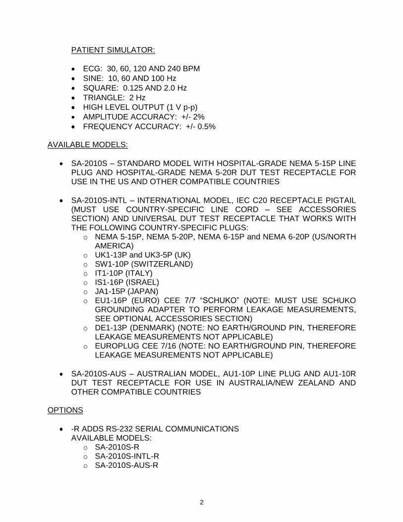
PATIENT SIMULATOR:
ECG: 30, 60, 120 AND 240 BPM
SINE: 10, 60 AND 100 Hz
SQUARE: 0.125 AND 2.0 Hz
TRIANGLE: 2 Hz
HIGH LEVEL OUTPUT (1 V p-p)
AMPLITUDE ACCURACY: +/- 2%
FREQUENCY ACCURACY: +/- 0.5% AVAILABLE MODELS:
SA-2010S – STANDARD MODEL WITH HOSPITAL-GRADE NEMA 5-15P LINE PLUG AND HOSPITAL-GRADE NEMA 5-20R DUT TEST RECEPTACLE FOR USE IN THE US AND OTHER COMPATIBLE COUNTRIES
SA-2010S-INTL – INTERNATIONAL MODEL, IEC C20 RECEPTACLE PIGTAIL (MUST USE COUNTRY-SPECIFIC LINE CORD – SEE ACCESSORIES SECTION) AND UNIVERSAL DUT TEST RECEPTACLE THAT WORKS WITH THE FOLLOWING COUNTRY-SPECIFIC PLUGS:
o NEMA 5-15P, NEMA 5-20P, NEMA 6-15P and NEMA 6-20P (US/NORTH AMERICA)
o UK1-13P and UK3-5P (UK) o SW1-10P (SWITZERLAND) o IT1-10P (ITALY) o IS1-16P (ISRAEL) o JA1-15P (JAPAN) o EU1-16P (EURO) CEE 7/7 “SCHUKO” (NOTE: MUST USE SCHUKO
GROUNDING ADAPTER TO PERFORM LEAKAGE MEASUREMENTS, SEE OPTIONAL ACCESSORIES SECTION)
o DE1-13P (DENMARK) (NOTE: NO EARTH/GROUND PIN, THEREFORE LEAKAGE MEASUREMENTS NOT APPLICABLE)
o EUROPLUG CEE 7/16 (NOTE: NO EARTH/GROUND PIN, THEREFORE LEAKAGE MEASUREMENTS NOT APPLICABLE)
SA-2010S-AUS – AUSTRALIAN MODEL, AU1-10P LINE PLUG AND AU1-10R DUT TEST RECEPTACLE FOR USE IN AUSTRALIA/NEW ZEALAND AND OTHER COMPATIBLE COUNTRIES
OPTIONS
-R ADDS RS-232 SERIAL COMMUNICATIONS AVAILABLE MODELS:
o SA-2010S-R o SA-2010S-INTL-R o SA-2010S-AUS-R
3
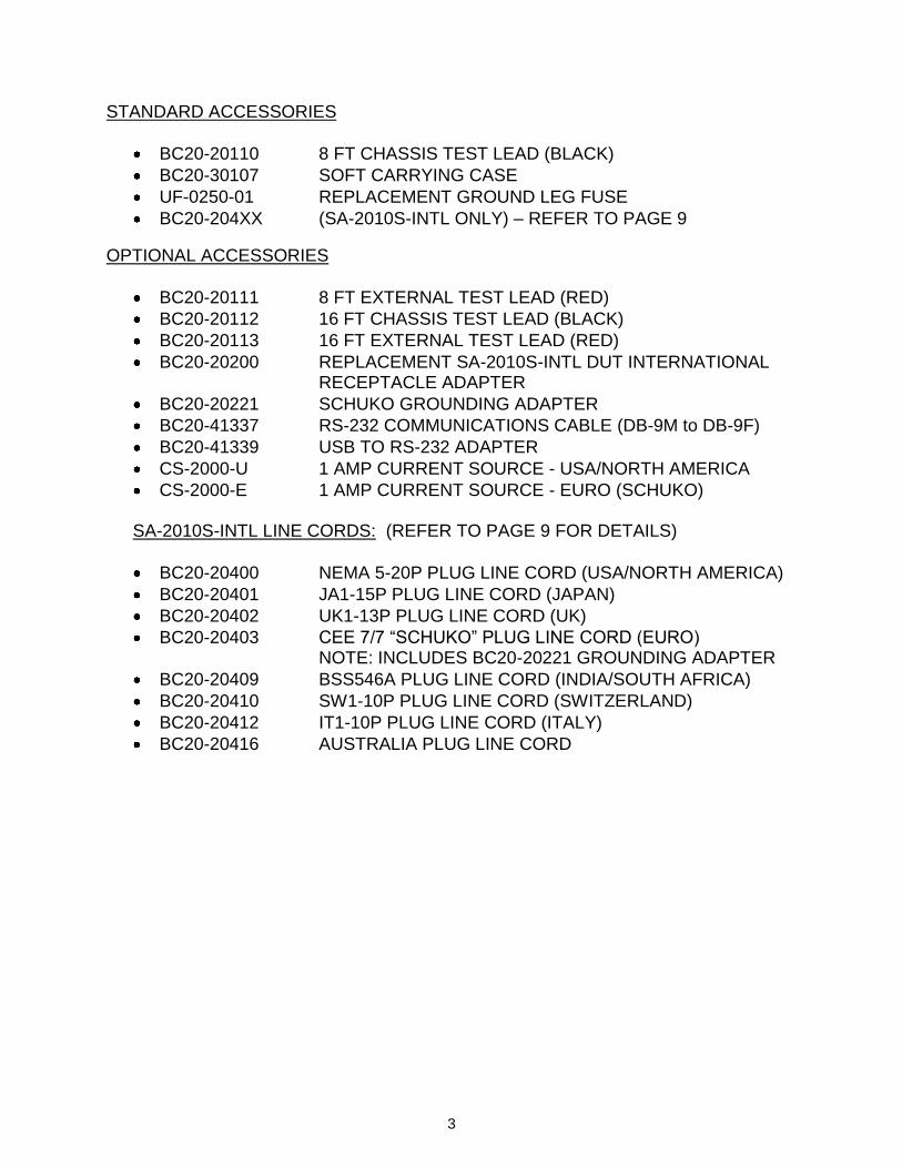
STANDARD ACCESSORIES
BC20-20110 8 FT CHASSIS TEST LEAD (BLACK)
BC20-30107 SOFT CARRYING CASE
UF-0250-01 REPLACEMENT GROUND LEG FUSE
BC20-204XX (SA-2010S-INTL ONLY) – REFER TO PAGE 9
OPTIONAL ACCESSORIES
BC20-20111 8 FT EXTERNAL TEST LEAD (RED)
BC20-20112 16 FT CHASSIS TEST LEAD (BLACK)
BC20-20113 16 FT EXTERNAL TEST LEAD (RED)
BC20-20200 REPLACEMENT SA-2010S-INTL DUT INTERNATIONAL RECEPTACLE ADAPTER
BC20-20221 SCHUKO GROUNDING ADAPTER
BC20-41337 RS-232 COMMUNICATIONS CABLE (DB-9M to DB-9F)
BC20-41339 USB TO RS-232 ADAPTER
CS-2000-U 1 AMP CURRENT SOURCE - USA/NORTH AMERICA
CS-2000-E 1 AMP CURRENT SOURCE - EURO (SCHUKO) SA-2010S-INTL LINE CORDS: (REFER TO PAGE 9 FOR DETAILS)
BC20-20400 NEMA 5-20P PLUG LINE CORD (USA/NORTH AMERICA)
BC20-20401 JA1-15P PLUG LINE CORD (JAPAN)
BC20-20402 UK1-13P PLUG LINE CORD (UK)
BC20-20403 CEE 7/7 “SCHUKO” PLUG LINE CORD (EURO) NOTE: INCLUDES BC20-20221 GROUNDING ADAPTER
BC20-20409 BSS546A PLUG LINE CORD (INDIA/SOUTH AFRICA)
BC20-20410 SW1-10P PLUG LINE CORD (SWITZERLAND)
BC20-20412 IT1-10P PLUG LINE CORD (ITALY)
BC20-20416 AUSTRALIA PLUG LINE CORD
4
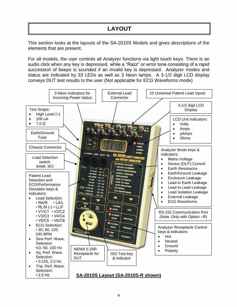
This section looks at the layouts of the SA-2010S Models and gives descriptions of the elements that are present. For all models, the user controls all Analyzer functions via light touch keys. There is an audio click when any key is depressed, while a “Razz” or error tone consisting of a rapid succession of beeps is sounded if an invalid key is depressed. Analyzer modes and status are indicated by 33 LEDs as well as 3 Neon lamps. A 3-1/2 digit LCD display conveys DUT test results to the user (Not applicable for ECG Waveforms mode)
SA-2010S Layout (SA-2010S-R shown)
LAYOUT
RS-232 Communication Port (Note: Only with Option –R)
3-1/2 digit LCD Display
ISO Test key & indicator
Load Selection switch:
AAMI, IEC
NEMA 5-20R Receptacle for DUT
Analyzer Mode keys & indicators:
Mains Voltage
Device (DUT) Current
Earth Resistance
Earth/Ground Leakage
Enclosure Leakage
Lead to Earth Leakage
Lead to Lead Leakage
Lead Isolation Leakage
External Leakage
ECG Waveforms
LCD Unit Indicators:
Volts
Amps
µAmps
Ohms
10 Universal Patient Lead Inputs
Chassis Connector
Patient Lead Selection and ECG/Performance Simulator keys & indicators:
Lead Selection: • RA/R • LA/L • RL/N (-) • LL/F • V1/C1 • V2/C2 • V3/C3 • V4/C4 • V5/C5 • V6/C6
ECG Selection: • 30, 60, 120, 240 BPM
Sine Perf. Wave. Selection:
•10, 60, 100 Hz
Sq. Perf. Wave. Selection:
• 0.125, 2.0 Hz
Tria. Perf. Wave. Selection:
• 2.0 Hz
Analyzer Receptacle Control keys & indicators:
Hot
Neutral
Ground
Polarity
Earth/Ground Fuse
Test Snaps:
High Level (+)
100 uA
1.0 Ω
External Lead Connector
3 Neon indicators for Incoming Power status
5
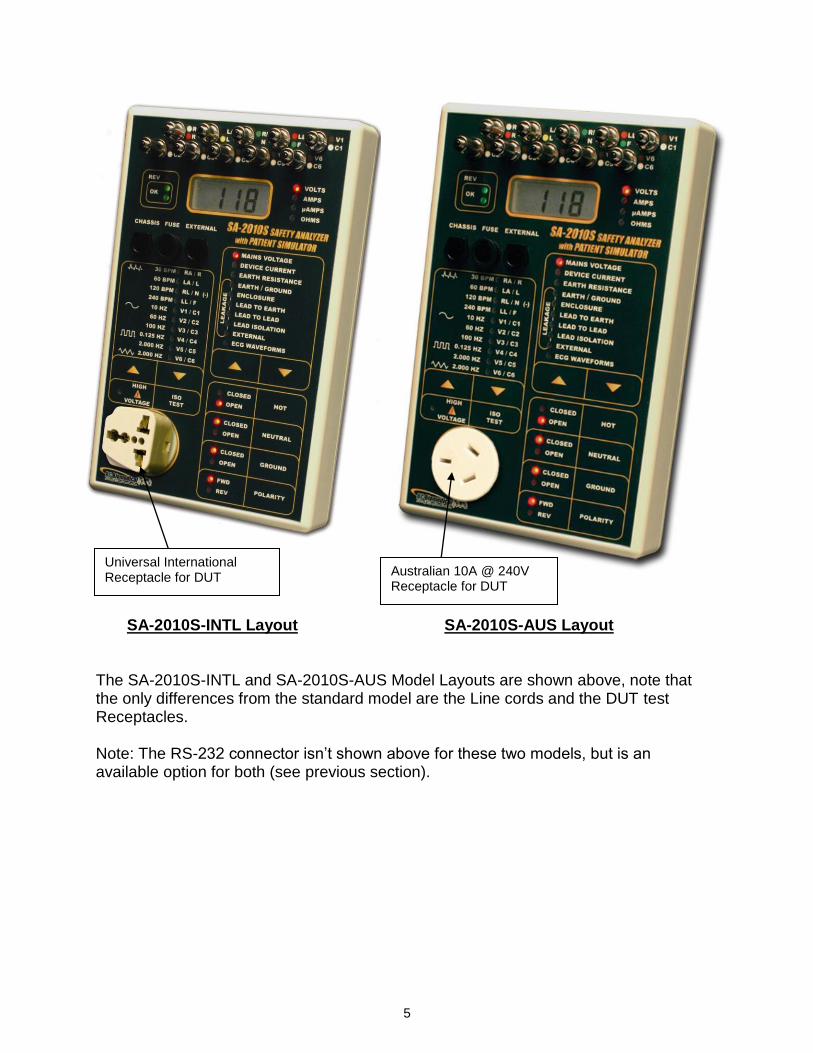
SA-2010S-INTL Layout SA-2010S-AUS Layout The SA-2010S-INTL and SA-2010S-AUS Model Layouts are shown above, note that the only differences from the standard model are the Line cords and the DUT test Receptacles. Note: The RS-232 connector isn’t shown above for these two models, but is an available option for both (see previous section).
Universal International Receptacle for DUT
Australian 10A @ 240V Receptacle for DUT
6
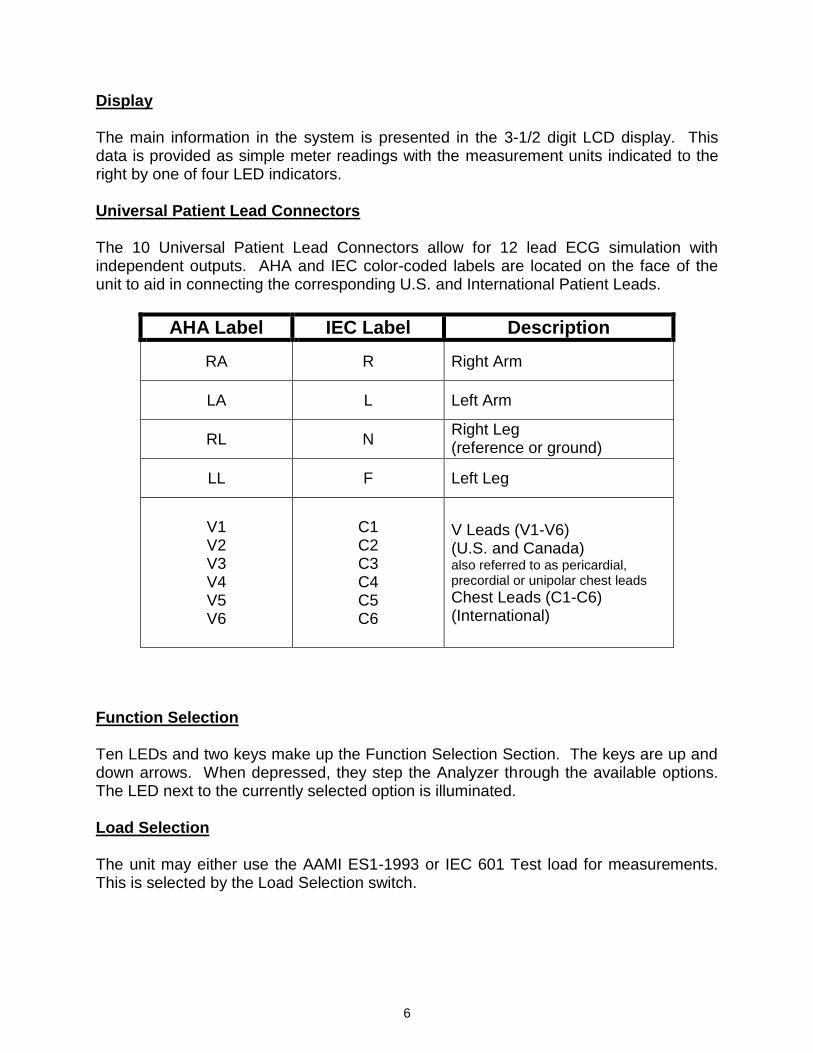
Display The main information in the system is presented in the 3-1/2 digit LCD display. This data is provided as simple meter readings with the measurement units indicated to the right by one of four LED indicators. Universal Patient Lead Connectors The 10 Universal Patient Lead Connectors allow for 12 lead ECG simulation with independent outputs. AHA and IEC color-coded labels are located on the face of the unit to aid in connecting the corresponding U.S. and International Patient Leads.
Function Selection Ten LEDs and two keys make up the Function Selection Section. The keys are up and down arrows. When depressed, they step the Analyzer through the available options. The LED next to the currently selected option is illuminated. Load Selection The unit may either use the AAMI ES1-1993 or IEC 601 Test load for measurements. This is selected by the Load Selection switch.
AHA Label IEC Label Description
RA R Right Arm
LA L Left Arm
RL N Right Leg (reference or ground)
LL F Left Leg
V1 V2 V3 V4 V5 V6
C1 C2 C3 C4 C5 C6
V Leads (V1-V6) (U.S. and Canada) also referred to as pericardial, precordial or unipolar chest leads
Chest Leads (C1-C6) (International)
7
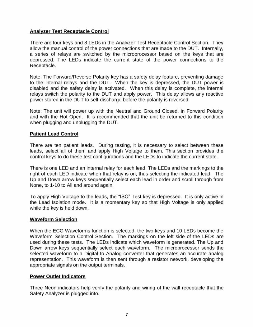
Analyzer Test Receptacle Control There are four keys and 8 LEDs in the Analyzer Test Receptacle Control Section. They allow the manual control of the power connections that are made to the DUT. Internally, a series of relays are switched by the microprocessor based on the keys that are depressed. The LEDs indicate the current state of the power connections to the Receptacle. Note: The Forward/Reverse Polarity key has a safety delay feature, preventing damage to the internal relays and the DUT. When the key is depressed, the DUT power is disabled and the safety delay is activated. When this delay is complete, the internal relays switch the polarity to the DUT and apply power. This delay allows any reactive power stored in the DUT to self-discharge before the polarity is reversed. Note: The unit will power up with the Neutral and Ground Closed, in Forward Polarity and with the Hot Open. It is recommended that the unit be returned to this condition when plugging and unplugging the DUT. Patient Lead Control There are ten patient leads. During testing, it is necessary to select between these leads, select all of them and apply High Voltage to them. This section provides the control keys to do these test configurations and the LEDs to indicate the current state. There is one LED and an internal relay for each lead. The LEDs and the markings to the right of each LED indicate when that relay is on, thus selecting the indicated lead. The Up and Down arrow keys sequentially select each lead in order and scroll through from None, to 1-10 to All and around again. To apply High Voltage to the leads, the “ISO” Test key is depressed. It is only active in the Lead Isolation mode. It is a momentary key so that High Voltage is only applied while the key is held down. Waveform Selection When the ECG Waveforms function is selected, the two keys and 10 LEDs become the Waveform Selection Control Section. The markings on the left side of the LEDs are used during these tests. The LEDs indicate which waveform is generated. The Up and Down arrow keys sequentially select each waveform. The microprocessor sends the selected waveform to a Digital to Analog converter that generates an accurate analog representation. This waveform is then sent through a resistor network, developing the appropriate signals on the output terminals. Power Outlet Indicators Three Neon indicators help verify the polarity and wiring of the wall receptacle that the Safety Analyzer is plugged into.
8
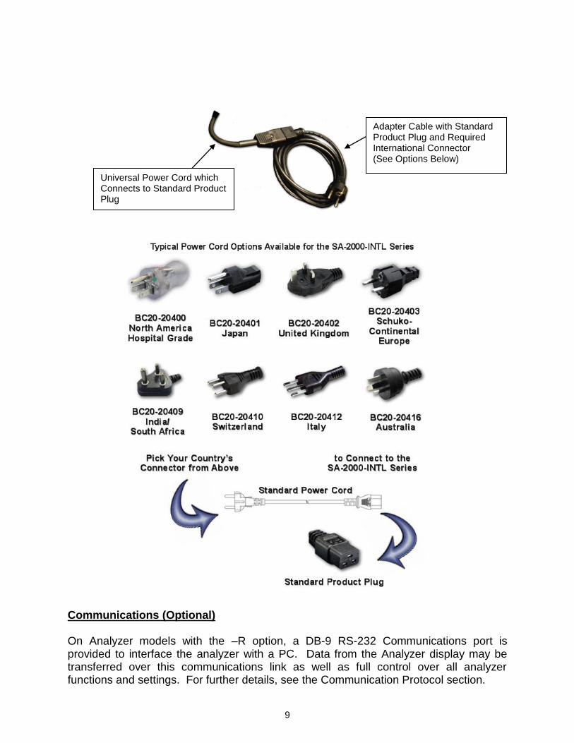
HI Level Output (+) A HI Level connector is located on the side of the unit for the high level ECG output signal (1 V p-p). The connection is between the High Level (+) snap and the RL (-) ECG lead. Self-Test Snaps There are two snaps on the side of the unit that allow for a quick self-test of the Analyzer. They provide a fixed 1.0 Ohm resistance to Earth/Ground and a 100 µAmp leakage current source to Earth/Ground when the Chassis lead is applied and the Analyzer set to the proper mode. Connectors There are two connectors for test cables on the unit. One is for the Chassis lead and the other is for one of two different leads used for external testing. The test cables simply plug into the sockets. There is a release pin on the cable plug that must be depressed to remove the cable. Fuse There is a fuse in the ground leg of the Analyzer Test Receptacle. This is to help prevent damage from excess ground current. It is located on the face for ease of replacement. Test Receptacle This receptacle is for the connection of the DUT. The Receptacle Rating depends on the specific Analyzer model. SA-2010S models use a Hospital Grade North American/USA standard NEMA 5-20R receptacle rated 20 Amps @ 125 VAC. SA-2010S-INTL models use a universal international receptacle rated 20 Amps @ 250 VAC. SA-2010S-AUS models use an Australian-specific AU1-10R receptacle rated 10 Amps @ 240 VAC. An external patch cord may be necessary to connect devices utilizing different types of plugs to the Analyzer receptacle. Power Cord The Power Cord, which is connected internally, provides power to both the Safety Analyzer and the DUT through the Test Receptacle. The Power Cord varies depending on the Analyzer model. SA-2010S models use a NEMA 5-15P plug designed to plug into a NEMA 5-15R or 5-20R Receptacle. SA-2010S-INTL models have a short IEC C20 plug for which a country-specific adapter cable must be connected – See the following section for this information. SA-2010S-AUS models use an Australian AU1-10P plug intended for operation with Australian and New Zealand AU1-10R Receptacles.
9
Communications (Optional) On Analyzer models with the –R option, a DB-9 RS-232 Communications port is provided to interface the analyzer with a PC. Data from the Analyzer display may be transferred over this communications link as well as full control over all analyzer functions and settings. For further details, see the Communication Protocol section.
Adapter Cable with Standard Product Plug and Required International Connector (See Options Below)
Universal Power Cord which Connects to Standard Product Plug
10
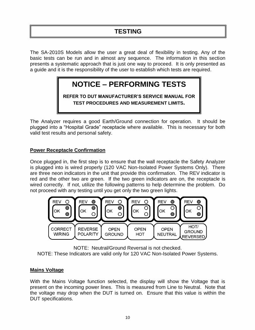
The SA-2010S Models allow the user a great deal of flexibility in testing. Any of the basic tests can be run and in almost any sequence. The information in this section presents a systematic approach that is just one way to proceed. It is only presented as a guide and it is the responsibility of the user to establish which tests are required. The Analyzer requires a good Earth/Ground connection for operation. It should be plugged into a “Hospital Grade” receptacle where available. This is necessary for both valid test results and personal safety. Power Receptacle Confirmation Once plugged in, the first step is to ensure that the wall receptacle the Safety Analyzer is plugged into is wired properly (120 VAC Non-Isolated Power Systems Only). There are three neon indicators in the unit that provide this confirmation. The REV indicator is red and the other two are green. If the two green indicators are on, the receptacle is wired correctly. If not, utilize the following patterns to help determine the problem. Do not proceed with any testing until you get only the two green lights. NOTE: Neutral/Ground Reversal is not checked.
NOTE: These Indicators are valid only for 120 VAC Non-Isolated Power Systems.
Mains Voltage With the Mains Voltage function selected, the display will show the Voltage that is present on the incoming power lines. This is measured from Line to Neutral. Note that the voltage may drop when the DUT is turned on. Ensure that this value is within the DUT specifications.
TESTING
NOTICE – PERFORMING TESTS
REFER TO DUT MANUFACTURER’S SERVICE MANUAL FOR
TEST PROCEDURES AND MEASUREMENT LIMITS.
11
Device Current With the Device Current function selected, the display will show the current draw of the DUT. The Receptacle should be configured with HOT-CLOSED, NEUTRAL-CLOSED, GROUND-CLOSED and POLARITY-FWD. Refer to the Specifications section for current capacity and permitted duty cycle for this test mode. Earth Resistance With the Earth Resistance function selected, the display will show the resistance between the Chassis Test lead and Receptacle Earth/Ground. This resistance is a combination of the resistance within the DUT enclosure and the resistance of the Earth/Ground Lead in the DUT power cord. NOTE: This test has no meaning for equipment that does not use a grounded cord. The test requires that the Chassis Test lead be plugged into the Chassis Connector. The other end should be connected to a solid ground point on the DUT. The display is in hundredths of Ω and will read to 19.99 Ω. Over-range shows as “1_ _ _”. Earth/Ground Leakage Current With the Earth/Ground Leakage function selected and the Ground-Open, the display will show the leakage current in the ground wire of the DUT. NOTE: This test has no meaning for equipment that does not use a grounded cord. Selecting this function automatically opens the connection to Earth/Ground and passes any leakage current through a 1000 Ω load with either AAMI ES1-1993 or IEC 601 frequency compensation as selected by the Load Selection switch. Enclosure Leakage With the Enclosure function selected, the display will show the leakage current between the Enclosure (Chassis) and Earth/Ground. The test requires that the Chassis Test lead be plugged into the Chassis Connector. The other end should be connected to a solid ground point on the DUT. NOTE: If a non-conductive enclosure is used, a 200 cm2 conductive foil pad should be used. This foil is to be placed in close contact with the enclosure and connected to the Chassis Test lead. Any leakage current will flow through the Chassis Test lead and then through a 1000 Ω load with either AAMI ES1-1993 or IEC 601 frequency compensation as selected by the Load Selection switch.
12
Lead to Earth/Ground Leakage With the Lead to Earth/Ground function selected, the display will show the leakage current between the selected lead and Earth/Ground. Attach the patient leads to the connectors on the top of the Safety Analyzer. The Up and Down arrow keys may then be used to select any individual lead or all of the leads. This test should be done for each lead individually and all leads together. This test measures the leakage current that would flow through the leads if the patient were to come into contact with Earth/Ground. Lead to Lead Leakage With the Lead to Lead function selected, the display will show the leakage current between the selected Patient Lead and all other patient leads. Attach the patient leads to the connectors on the top of the Safety Analyzer. The Up and Down arrow keys may then be used to select any individual lead. Internally, relays connect the leads as necessary. The LEDs indicate the selected lead. This test should be done for each lead individually. This test measures the current that would flow from a lead to other leads. Normally these are Auxiliary currents from bias, measurement and sensing circuits. Lead Isolation With the Lead Isolation function selected and the “ISO” Test key depressed, the display will show the leakage current between the selected Patient Lead(s) and Earth/Ground. Attach the patient leads to the connectors on the top of the Safety Analyzer. The Up and Down arrow keys may then be used to select any individual lead and all of the leads.
WARNING The SA-2010S applies 110% of line voltage to the
Patient leads or External test leads during the Isolation test. Although this is current limited by
a 121 kΩ internal resistor, per standard test specifications, care should be taken to prevent contact with this voltage. Do not touch the test leads, connections or DUT while depressing the
Isolation Test key.
13
As each lead and then All leads are selected, depress and hold the “ISO” Test key. This will apply 110% of the line voltage through a 121 kΩ resistor to the selected lead(s) and measure the current that flows to Earth/Ground through a 1000 Ω load with either AAMI ES1-1993 or IEC 601 frequency compensation as selected by the Load Selection switch. This test is to be done for each lead individually and All leads together. This test measures the leakage current that would flow through the lead(s) if the patient were to come into contact with Line voltage. This is referred to as MAP (MAINS on Applied Parts). Point to Point Measurements The unit has the ability to measure Leakage Current, Isolation Leakage Current and Resistance between two points, utilizing two test leads. These tests are separated because they use a slightly different setup than the previous tests. Point to Point Leakage Current With the External function selected, the display will show the leakage current between the test leads. The test requires that the Chassis Test lead be plugged into the Chassis Connector and the External Test lead be plugged into the External Connector. The other ends of the leads are then attached to the points of interest. Any current flowing between the test points is passed through a 1000 Ω load with either AAMI ES1-1993 or IEC 601 frequency compensation as selected by the Load Selection switch. Point to Point Isolation Leakage Current With the External function selected and the “ISO” Test key depressed, the display will show the isolation leakage current between the test leads.
WARNING The SA-2010S applies 110% of line voltage to the
Patient leads or External test leads during the Isolation test. Although this is current limited by
a 121 kΩ internal resistor, per standard test specifications, care should be taken to prevent contact with this voltage. Do not touch the test leads, connections or DUT while depressing the
Isolation Test key.
14
The test requires that the Chassis Test lead be plugged into the Chassis Connector and the External Test lead be plugged into the External Connector. The other ends of the leads are then attached to the points of interest. Depress and hold the Isolation Voltage key. This will apply 110% of the line voltage through a 121 kΩ resistor to the test leads and measure the current that flows through a 1000 Ω load with either AAMI ES1-1993 or IEC 601 frequency compensation as selected by the Load Selection switch. Point to Point Resistance With the Earth Resistance function selected, the display will show the resistance between the two test leads. The test requires two Chassis Test leads, one in the Chassis Connector and the second in the External Connector. The opposite cable ends should be connected to the points of interest. NOTE: Remove any device plugged into the Analyzer Test Receptacle. If there is a DC voltage present between the two test points, the reading may contain an error. This can be checked by reversing the connections. If the readings differ, average the two to get the actual resistance value.
15
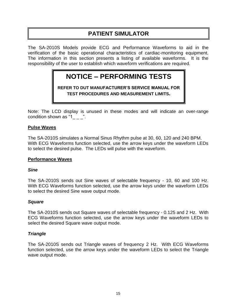
The SA-2010S Models provide ECG and Performance Waveforms to aid in the verification of the basic operational characteristics of cardiac-monitoring equipment. The information in this section presents a listing of available waveforms. It is the responsibility of the user to establish which waveform verifications are required. Note: The LCD display is unused in these modes and will indicate an over-range condition shown as “1_ _ _”. Pulse Waves The SA-2010S simulates a Normal Sinus Rhythm pulse at 30, 60, 120 and 240 BPM. With ECG Waveforms function selected, use the arrow keys under the waveform LEDs to select the desired pulse. The LEDs will pulse with the waveform. Performance Waves Sine The SA-2010S sends out Sine waves of selectable frequency - 10, 60 and 100 Hz. With ECG Waveforms function selected, use the arrow keys under the waveform LEDs to select the desired Sine wave output mode. Square The SA-2010S sends out Square waves of selectable frequency - 0.125 and 2 Hz. With ECG Waveforms function selected, use the arrow keys under the waveform LEDs to select the desired Square wave output mode. Triangle The SA-2010S sends out Triangle waves of frequency 2 Hz. With ECG Waveforms function selected, use the arrow keys under the waveform LEDs to select the Triangle wave output mode.
PATIENT SIMULATOR
NOTICE – PERFORMING TESTS
REFER TO DUT MANUFACTURER’S SERVICE MANUAL FOR
TEST PROCEDURES AND MEASUREMENT LIMITS.
16
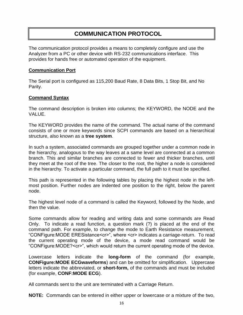
The communication protocol provides a means to completely configure and use the Analyzer from a PC or other device with RS-232 communications interface. This provides for hands free or automated operation of the equipment. Communication Port The Serial port is configured as 115,200 Baud Rate, 8 Data Bits, 1 Stop Bit, and No Parity. Command Syntax
The command description is broken into columns; the KEYWORD, the NODE and the VALUE. The KEYWORD provides the name of the command. The actual name of the command consists of one or more keywords since SCPI commands are based on a hierarchical structure, also known as a tree system. In such a system, associated commands are grouped together under a common node in the hierarchy, analogous to the way leaves at a same level are connected at a common branch. This and similar branches are connected to fewer and thicker branches, until they meet at the root of the tree. The closer to the root, the higher a node is considered in the hierarchy. To activate a particular command, the full path to it must be specified. This path is represented in the following tables by placing the highest node in the left-most position. Further nodes are indented one position to the right, below the parent node. The highest level node of a command is called the Keyword, followed by the Node, and then the value. Some commands allow for reading and writing data and some commands are Read Only. To indicate a read function, a question mark (?) is placed at the end of the command path. For example, to change the mode to Earth Resistance measurement, “CONFigure:MODE ERESistance<cr>”, where <cr> indicates a carriage-return. To read the current operating mode of the device, a mode read command would be “CONFigure:MODE?<cr>”, which would return the current operating mode of the device. Lowercase letters indicate the long-form of the command (for example, CONFigure:MODE ECGwaveforms) and can be omitted for simplification. Uppercase letters indicate the abbreviated, or short-form, of the commands and must be included (for example, CONF:MODE ECG). All commands sent to the unit are terminated with a Carriage Return. NOTE: Commands can be entered in either upper or lowercase or a mixture of the two,
COMMUNICATION PROTOCOL
17
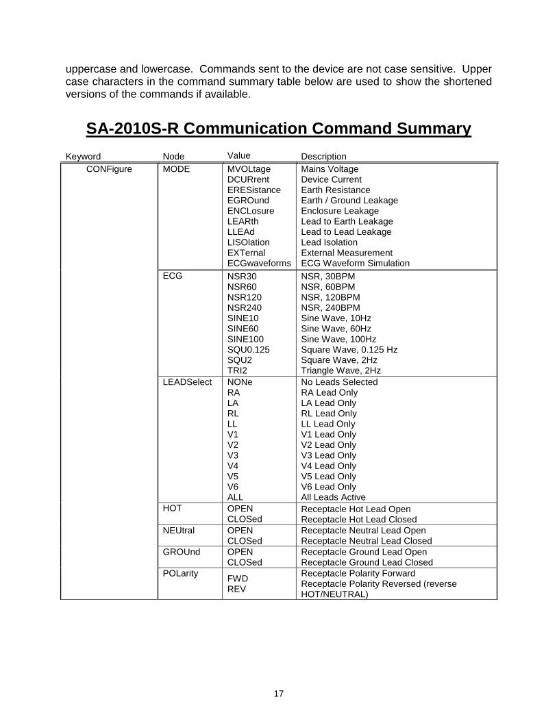
uppercase and lowercase. Commands sent to the device are not case sensitive. Upper case characters in the command summary table below are used to show the shortened versions of the commands if available.
SA-2010S-R Communication Command Summary
Keyword Node Value Description
CONFigure MODE MVOLtage DCURrent ERESistance EGROund ENCLosure LEARth LLEAd LISOlation EXTernal ECGwaveforms
Mains Voltage Device Current Earth Resistance Earth / Ground Leakage Enclosure Leakage Lead to Earth Leakage Lead to Lead Leakage Lead Isolation External Measurement ECG Waveform Simulation
ECG NSR30 NSR60 NSR120 NSR240 SINE10 SINE60 SINE100 SQU0.125 SQU2 TRI2
NSR, 30BPM NSR, 60BPM NSR, 120BPM NSR, 240BPM Sine Wave, 10Hz Sine Wave, 60Hz Sine Wave, 100Hz Square Wave, 0.125 Hz Square Wave, 2Hz Triangle Wave, 2Hz
LEADSelect NONe RA LA RL LL V1 V2 V3 V4 V5 V6 ALL
No Leads Selected RA Lead Only LA Lead Only RL Lead Only LL Lead Only V1 Lead Only V2 Lead Only V3 Lead Only V4 Lead Only V5 Lead Only V6 Lead Only All Leads Active
HOT OPEN
CLOSed Receptacle Hot Lead Open Receptacle Hot Lead Closed
NEUtral OPEN
CLOSed Receptacle Neutral Lead Open Receptacle Neutral Lead Closed
GROUnd OPEN
CLOSed Receptacle Ground Lead Open Receptacle Ground Lead Closed
POLarity
FWD REV
Receptacle Polarity Forward Receptacle Polarity Reversed (reverse HOT/NEUTRAL)
18
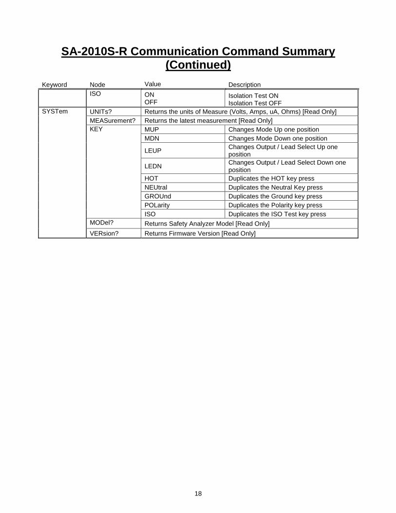
SA-2010S-R Communication Command Summary (Continued)
Keyword Node Value Description
ISO ON
OFF Isolation Test ON Isolation Test OFF
SYSTem UNITs? Returns the units of Measure (Volts, Amps, uA, Ohms) [Read Only]
MEASurement? Returns the latest measurement [Read Only]
KEY MUP Changes Mode Up one position
MDN Changes Mode Down one position
LEUP Changes Output / Lead Select Up one position
LEDN Changes Output / Lead Select Down one position
HOT Duplicates the HOT key press
NEUtral Duplicates the Neutral Key press
GROUnd Duplicates the Ground key press
POLarity Duplicates the Polarity key press
ISO Duplicates the ISO Test key press
MODel? Returns Safety Analyzer Model [Read Only]
VERsion? Returns Firmware Version [Read Only]
19
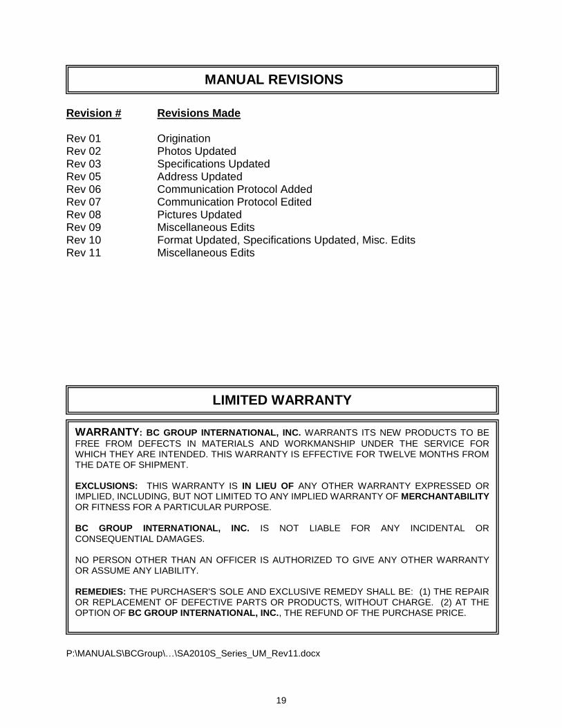
Revision # Revisions Made Rev 01 Origination Rev 02 Photos Updated Rev 03 Specifications Updated Rev 05 Address Updated Rev 06 Communication Protocol Added Rev 07 Communication Protocol Edited Rev 08 Pictures Updated Rev 09 Miscellaneous Edits Rev 10 Format Updated, Specifications Updated, Misc. Edits Rev 11 Miscellaneous Edits P:\MANUALS\BCGroup\…\SA2010S_Series_UM_Rev11.docx
LIMITED WARRANTY
WARRANTY: BC GROUP INTERNATIONAL, INC. WARRANTS ITS NEW PRODUCTS TO BE
FREE FROM DEFECTS IN MATERIALS AND WORKMANSHIP UNDER THE SERVICE FOR WHICH THEY ARE INTENDED. THIS WARRANTY IS EFFECTIVE FOR TWELVE MONTHS FROM THE DATE OF SHIPMENT. EXCLUSIONS: THIS WARRANTY IS IN LIEU OF ANY OTHER WARRANTY EXPRESSED OR IMPLIED, INCLUDING, BUT NOT LIMITED TO ANY IMPLIED WARRANTY OF MERCHANTABILITY OR FITNESS FOR A PARTICULAR PURPOSE. BC GROUP INTERNATIONAL, INC. IS NOT LIABLE FOR ANY INCIDENTAL OR CONSEQUENTIAL DAMAGES. NO PERSON OTHER THAN AN OFFICER IS AUTHORIZED TO GIVE ANY OTHER WARRANTY OR ASSUME ANY LIABILITY. REMEDIES: THE PURCHASER'S SOLE AND EXCLUSIVE REMEDY SHALL BE: (1) THE REPAIR OR REPLACEMENT OF DEFECTIVE PARTS OR PRODUCTS, WITHOUT CHARGE. (2) AT THE OPTION OF BC GROUP INTERNATIONAL, INC., THE REFUND OF THE PURCHASE PRICE.
MANUAL REVISIONS
20
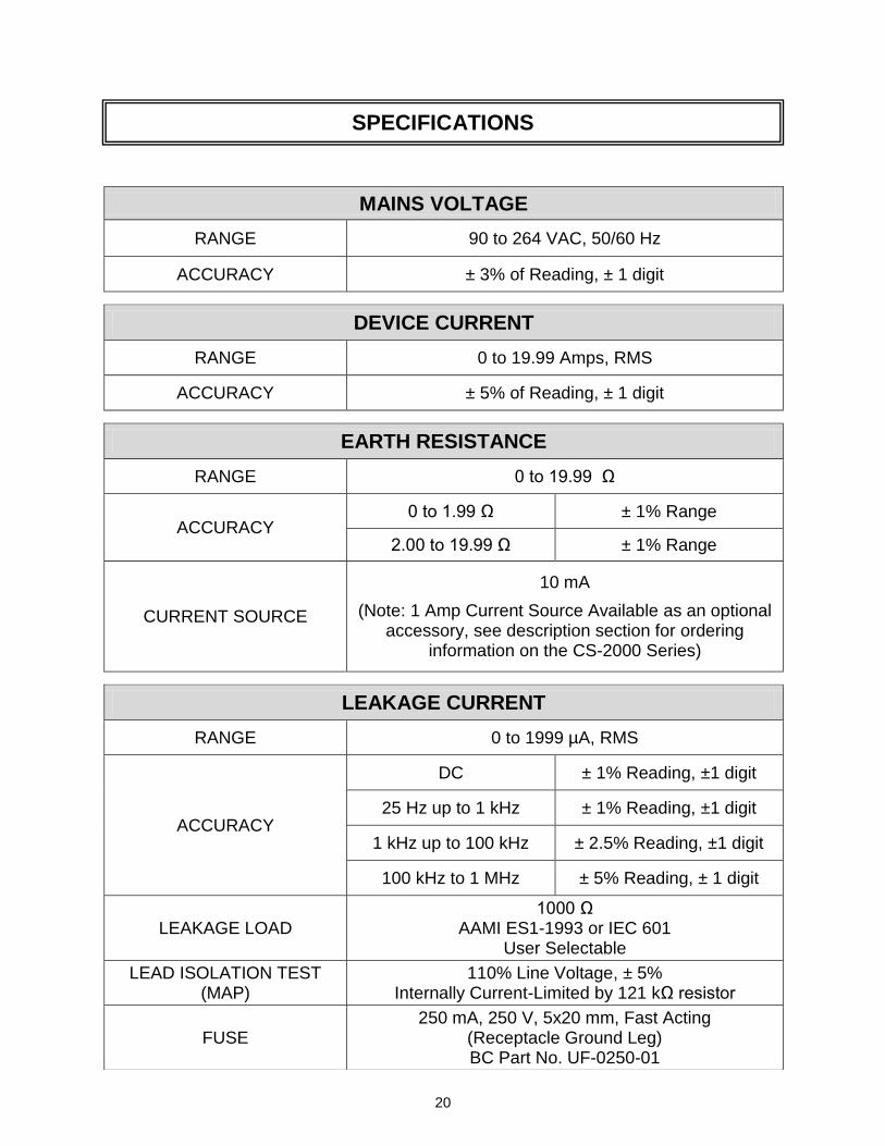
MAINS VOLTAGE
RANGE 90 to 264 VAC, 50/60 Hz
ACCURACY ± 3% of Reading, ± 1 digit
DEVICE CURRENT
RANGE 0 to 19.99 Amps, RMS
ACCURACY ± 5% of Reading, ± 1 digit
EARTH RESISTANCE
RANGE 0 to 19.99 Ω
ACCURACY 0 to 1.99 Ω ± 1% Range
2.00 to 19.99 Ω ± 1% Range
CURRENT SOURCE
10 mA
(Note: 1 Amp Current Source Available as an optional accessory, see description section for ordering
information on the CS-2000 Series)
LEAKAGE CURRENT
RANGE 0 to 1999 µA, RMS
ACCURACY
DC ± 1% Reading, ±1 digit
25 Hz up to 1 kHz ± 1% Reading, ±1 digit
1 kHz up to 100 kHz ± 2.5% Reading, ±1 digit
100 kHz to 1 MHz ± 5% Reading, ± 1 digit
LEAKAGE LOAD 1000 Ω
AAMI ES1-1993 or IEC 601 User Selectable
LEAD ISOLATION TEST (MAP)
110% Line Voltage, ± 5% Internally Current-Limited by 121 kΩ resistor
FUSE 250 mA, 250 V, 5x20 mm, Fast Acting
(Receptacle Ground Leg) BC Part No. UF-0250-01
SPECIFICATIONS
21
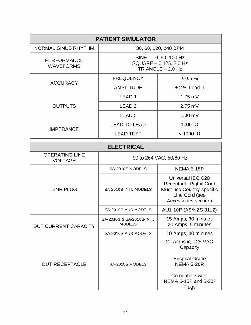
PATIENT SIMULATOR
NORMAL SINUS RHYTHM 30, 60, 120, 240 BPM
PERFORMANCE WAVEFORMS
SINE – 10, 60, 100 Hz SQUARE – 0.125, 2.0 Hz
TRIANGLE – 2.0 Hz
ACCURACY FREQUENCY ± 0.5 %
AMPLITUDE ± 2 % Lead II
OUTPUTS
LEAD 1 1.75 mV
LEAD 2 2.75 mV
LEAD 3 1.00 mV
IMPEDANCE LEAD TO LEAD 1000 Ω
LEAD TEST < 1000 Ω
ELECTRICAL
OPERATING LINE VOLTAGE
90 to 264 VAC, 50/60 Hz
LINE PLUG
SA-2010S MODELS NEMA 5-15P
SA-2010S-INTL MODELS
Universal IEC C20 Receptacle Pigtail Cord
Must use Country-specific Line Cord (see
Accessories section)
SA-2010S-AUS MODELS AU1-10P (AS/NZS 3112)
DUT CURRENT CAPACITY
SA-2010S & SA-2010S-INTL MODELS
15 Amps, 30 minutes 20 Amps, 5 minutes
SA-2010S-AUS MODELS 10 Amps, 30 minutes
DUT RECEPTACLE SA-2010S MODELS
20 Amps @ 125 VAC Capacity
Hospital Grade NEMA 5-20R
Compatible with:
NEMA 5-15P and 5-20P Plugs
22
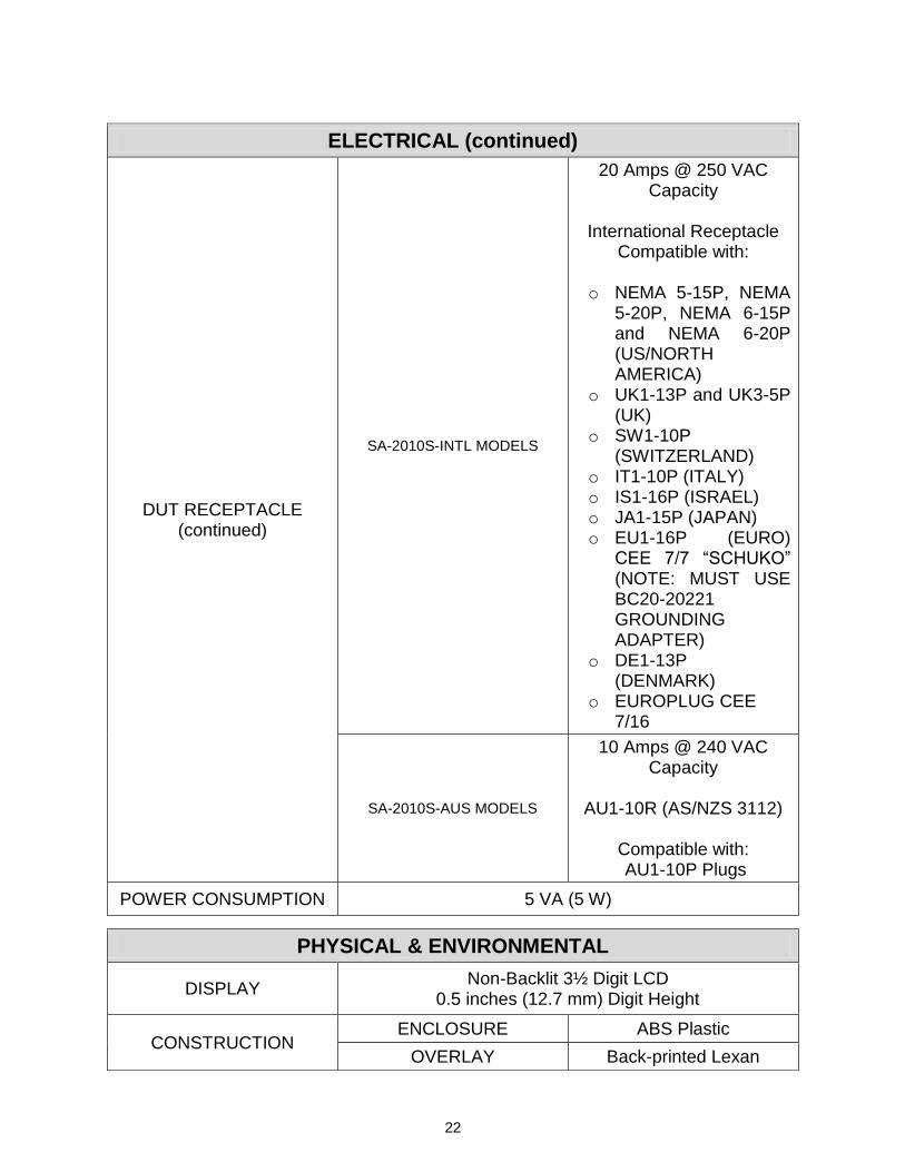
ELECTRICAL (continued)
DUT RECEPTACLE (continued)
SA-2010S-INTL MODELS
20 Amps @ 250 VAC Capacity
International Receptacle
Compatible with:
o NEMA 5-15P, NEMA 5-20P, NEMA 6-15P and NEMA 6-20P (US/NORTH AMERICA)
o UK1-13P and UK3-5P (UK)
o SW1-10P (SWITZERLAND)
o IT1-10P (ITALY) o IS1-16P (ISRAEL) o JA1-15P (JAPAN) o EU1-16P (EURO)
CEE 7/7 “SCHUKO” (NOTE: MUST USE BC20-20221 GROUNDING ADAPTER)
o DE1-13P (DENMARK)
o EUROPLUG CEE 7/16
SA-2010S-AUS MODELS
10 Amps @ 240 VAC Capacity
AU1-10R (AS/NZS 3112)
Compatible with: AU1-10P Plugs
POWER CONSUMPTION 5 VA (5 W)
PHYSICAL & ENVIRONMENTAL
DISPLAY Non-Backlit 3½ Digit LCD
0.5 inches (12.7 mm) Digit Height
CONSTRUCTION ENCLOSURE ABS Plastic
OVERLAY Back-printed Lexan
23
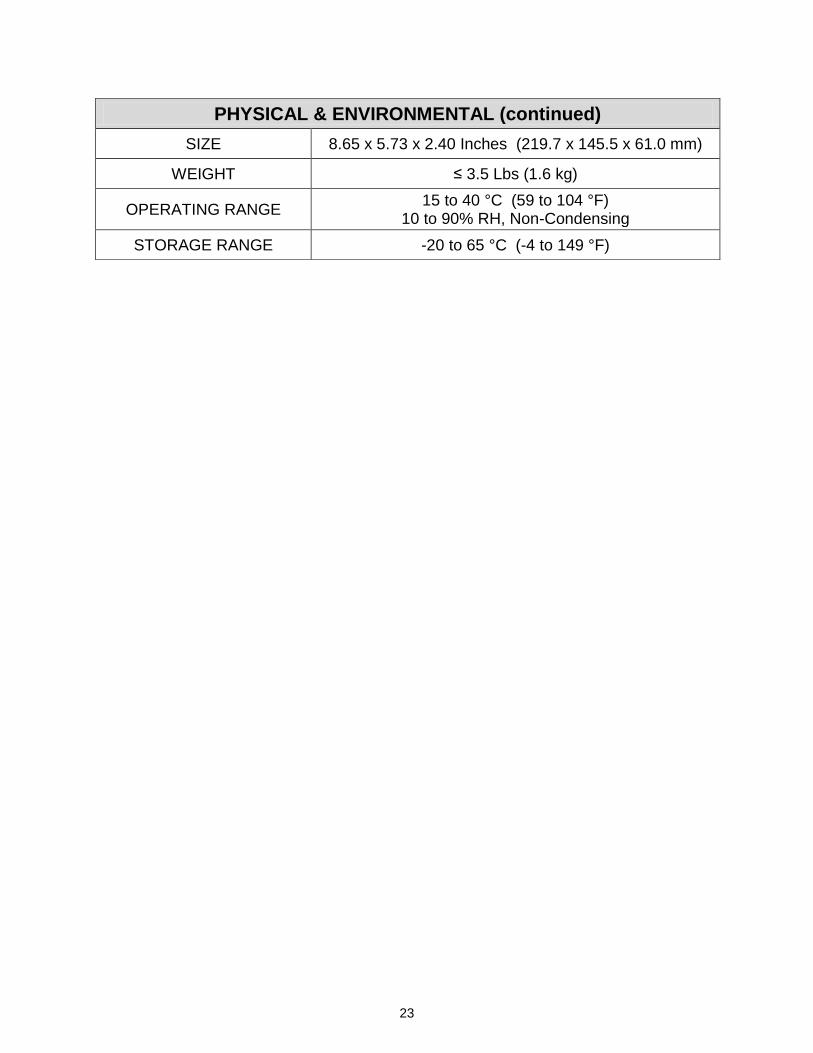
PHYSICAL & ENVIRONMENTAL (continued)
SIZE 8.65 x 5.73 x 2.40 Inches (219.7 x 145.5 x 61.0 mm)
WEIGHT ≤ 3.5 Lbs (1.6 kg)
OPERATING RANGE 15 to 40 °C (59 to 104 °F)
10 to 90% RH, Non-Condensing
STORAGE RANGE -20 to 65 °C (-4 to 149 °F)

24
NOTES

25
NOTES

26
NOTES


BC GROUP INTERNATIONAL, INC. 3081 ELM POINT INDUSTRIAL DRIVE
ST. CHARLES, MO 63301 USA
1-800-242-8428 1-314-638-3800
www.bcgroupintl.com
SA-2010S Series User Manual 06/12 – Rev 11
Copyright © 2012 Made in the USA