Embed Size (px)
Citation preview
T HR EL 00006 ST
Standard
Electrical Power System Signage
Version 1.0
Issued date: 04 March 2016
Important Warning This document is one of a set of standards developed solely and specifically for use on Transport Assets (as defined in the Asset Standards Authority Charter). It is not suitable for any other purpose. You must not use or adapt it or rely upon it in any way unless you are authorised in writing to do so by a relevant NSW Government agency. If this document forms part of a contract with, or is a condition of approval by a NSW Government agency, use of the document is subject to the terms of the contract or approval. This document is uncontrolled when printed or downloaded. Users should exercise their own skill and care in the use of the document. This document may not be current. Current standards may be accessed from the Asset Standards Authority website at www.asa.transport.nsw.gov.au. © State of NSW through Transport for NSW
T HR EL 00006 ST Electrical Power System Signage
Version 1.0 Issued date: 04 March 2016
Standard governance
Owner: Lead Electrical Engineer, Asset Standards Authority
Authoriser: Chief Engineer Rail, Asset Standards Authority
Approver Executive Director, Asset Standards Authority on behalf of the ASA Configuration Control Board
Document history
Version Summary of Changes
1.0 First issue
For queries regarding this document, please email the ASA at [email protected] or visit www.asa.transport.nsw.gov.au
© State of NSW through Transport for NSW
T HR EL 00006 ST Electrical Power System Signage
Version 1.0 Issued date: 04 March 2016
Preface The Asset Standards Authority (ASA) is an independent unit within Transport for NSW (TfNSW)
and is the network design and standards authority for defined NSW transport assets.
The ASA is responsible for developing engineering governance frameworks to support industry
delivery in the assurance of design, safety, integrity, construction, and commissioning of
transport assets for the whole asset life cycle. In order to achieve this, the ASA effectively
discharges obligations as the authority for various technical, process, and planning matters
across the asset life cycle.
The ASA collaborates with industry using stakeholder engagement activities to assist in
achieving its mission. These activities help align the ASA to broader government expectations
of making it clearer, simpler, and more attractive to do business within the NSW transport
industry, allowing the supply chain to deliver safe, efficient, and competent transport services.
The ASA develops, maintains, controls, and publishes a suite of standards and other
documentation for transport assets of TfNSW. Further, the ASA ensures that these standards
are performance-based to create opportunities for innovation and improve access to a broader
competitive supply chain.
This standard has been derived from EP 00 00 00 16 SP Electrical Power System Signage,
Version 2.1. This standard supersedes EP 00 00 00 16 SP.
This standard is a first issue and the changes to previous content include the following:
• updates to reflect organisational change resulting in responsibilities
• amendments and clarification to content
• conversion of standard to ASA numbering, style and format
© State of NSW through Transport for NSW Page 3 of 37
T HR EL 00006 ST Electrical Power System Signage
Version 1.0 Issued date: 04 March 2016
Table of contents 1. Introduction .............................................................................................................................................. 6
2. Purpose .................................................................................................................................................... 62.1. Scope ..................................................................................................................................................... 62.2. Application ............................................................................................................................................. 6
3. Reference documents ............................................................................................................................. 7
4. Terms and definitions ............................................................................................................................. 8
5. General ..................................................................................................................................................... 95.1. Signage purpose .................................................................................................................................... 95.2. General signage requirements .............................................................................................................. 95.3. Signage placement .............................................................................................................................. 105.4. Sign visibility ........................................................................................................................................ 105.5. Signage mounting ................................................................................................................................ 11
6. Safety signs ............................................................................................................................................ 116.1. External fencing ................................................................................................................................... 126.2. External access doors and gates ........................................................................................................ 136.3. Internal fences and barriers ................................................................................................................. 146.4. Electrical emergency – telephone number .......................................................................................... 146.5. High voltage equipment ....................................................................................................................... 166.6. Direct current circuit breakers .............................................................................................................. 176.7. Low voltage equipment ........................................................................................................................ 186.8. Confined space .................................................................................................................................... 196.9. 1500 V negatives ................................................................................................................................. 20
7. Emergency information ........................................................................................................................ 207.1. Resuscitation instructions and first aid ................................................................................................ 207.2. Battery rooms and areas ..................................................................................................................... 21
8. Information and warning signs ............................................................................................................ 238.1. High voltage busbars ........................................................................................................................... 238.2. Earth points .......................................................................................................................................... 248.3. Voltmeter test rail – warning ................................................................................................................ 248.4. Traction negative do not bridge to earth – warning ............................................................................. 258.5. Fire equipment ..................................................................................................................................... 268.6. WHS signs ........................................................................................................................................... 268.7. Hazardous materials ............................................................................................................................ 278.8. Capacitor warning ................................................................................................................................ 288.9. Exit signs.............................................................................................................................................. 298.10. Electrical permit – warning sign ....................................................................................................... 29
9. Distribution substations ....................................................................................................................... 309.1. 33 kV pole mounted distribution substation ......................................................................................... 309.2. 11 kV pole mounted distribution substation ......................................................................................... 31
© State of NSW through Transport for NSW Page 4 of 37
T HR EL 00006 ST Electrical Power System Signage
Version 1.0 Issued date: 04 March 2016
9.3. Walk-in distribution substations ........................................................................................................... 339.4. Padmount locations ............................................................................................................................. 35
10. Location name ....................................................................................................................................... 36
11. Tunnel normal lighting signage ........................................................................................................... 37
12. Further reading ...................................................................................................................................... 37
© State of NSW through Transport for NSW Page 5 of 37
T HR EL 00006 ST Electrical Power System Signage
Version 1.0 Issued date: 04 March 2016
1. Introduction Appropriate signage is fundamental to the safe operation and maintenance of Transport for
NSW (TfNSW) electrical power system assets. Having clear signage that draws people's
attention to danger, and identifies who may enter or use a part of the electrical power system, is
important for the safety of TfNSW employees, contractors, and the public.
2. Purpose This document details the standards for signage for many types of locations in the electrical
power system. Compliance with this standard, at a minimum, by those working on the Transport
assets is necessary for a safe electrical power system.
2.1. Scope This document identifies minimum compliance standards for safety and safety related signage
to be used in and around railway system substations, sectioning huts, distribution substations,
and low voltage (LV) lighting in tunnels.
This document does not include signage that is for operating within substations. It does cover
the safety signs that are mandatory and provide a warning that a danger exists and that caution
should be taken in that area.
Signage for other railway power system locations, including overhead wiring and high voltage
(HV) aerial lines, will be included in later versions of this document.
This document provides general guidance for selection and placement of signage and includes
judgement criteria to assist in determining whether action is required for amendment to
pre-existing signage.
2.2. Application If signage installed prior to the issue of this document is in good condition and meets the
essential purpose of signage as defined in this document, then it may remain in service.
New and replacement signs shall be as stated in this document.
This document covers minimum practice and does not restrict the use of additional warning,
hazard, and emergency signs where additional local hazards have been identified.
Where equipment manufacturers have supplied equipment with various hazard warnings and
operating instructions attached, these warning signs should remain on the equipment, provided
they do not impede their operation or provide misleading or contradictory information.
Where signs are developed because of a specific need not covered by this document, then the
sign is to be manufactured in accordance with the relevant Australian Standard.
© State of NSW through Transport for NSW Page 6 of 37
T HR EL 00006 ST Electrical Power System Signage
Version 1.0 Issued date: 04 March 2016
For the purpose of safety, the signage that covers 1500 V dc is to be dealt with in the same
manner as high voltage.
3. Reference documents The following documents are cited in the text. For dated references, only the cited edition
applies. For undated references, the latest edition of the referenced document applies.
Australian standards
AS 1319-1994 Safety signs for the occupational environment
AS 2067-2008 Substations and high voltage installations exceeding 1 kV a.c.
AS 2293.1-2005 Emergency escape lighting and exit signs for buildings – System design,
installation and operation
AS 2444-2001 Portable fire extinguishers and fire blankets – Selection and location
AS 2676.1-1992 Guide to the installation, maintenance, testing and replacement of secondary
batteries in buildings – Vented cells
AS 2676.2-1992 Guide to the installation, maintenance, testing and replacement of secondary
batteries in buildings – Sealed cells
AS 2700S-2011 (R13) Colour standards for general purposes – Signal Red
AS 2865-2009 Confined spaces
AS/NZS 3000-2007 Electrical installations (known as the Australian/New Zealand Wiring Rules)
Transport for NSW standards
EP 00 00 00 07 SP Requirements for Handling & Disposal of Materials Containing PCB
EP 20 00 00 03 SP Above Ground Cable Installation Systems – Selection Guide
EP 99 00 00 01 SP Substations Minimum Construction Standards
SMS-06-GD-0268 Working near Electrical Equipment
T HR EL 10001 ST HV Aerial Line Standards for Design and Construction
EP 99 00 00 07 SP Substation Fencing
Transport for NSW drawings
Drawings listed are available from the Sydney Trains Plan Room
EL0008409 33 kV / 500 – 250 V Transformer Single Pole Structure Operating Notice
EL0228600 Substations Earth Disc
EL0282878 High Voltage Aerial Lines and Cables - Electrical Cable Route Markers – Vertical
Marker Plate Manufacturing Details © State of NSW through Transport for NSW Page 7 of 37
T HR EL 00006 ST Electrical Power System Signage
Version 1.0 Issued date: 04 March 2016
EL0283014 Substations Confined Space – Danger Sign
EL0283015 Substations First Aid & Battery – Safety Sign
EL0283016 Substations HV Authorised Personnel Only – Danger Sign
EL0283017 Substations Personal Protective Equipment – Safety Sign
EL0283018 Substations Capacitor HV Discharge – Warning Sign
EL0283019 Substations 1500 Volt Negatives – Danger Sign (large)
EL0283020 Substations 415 Volts - Danger Sign
EL0283021 High Voltage Overhead – Danger Sign
EL0283022 Substations 11kV/415-240V Transformer – Warning Sign
EL0283023 Substations Voltmeter Test Rail – Warning Sign
EL0284401 Substations Confined Space – Danger Sign – With Arrow
EL0474383 Substations High Voltage – Danger Sign
EL0474385 Substations Electrical Emergency – Sign
EL0474387 Substations Danger High Voltage Keep Out – Fence Sign
EL0474485 Substations Danger High Voltage Keep Out – Padmount
EL0474490 Substations Danger Electrical Equipment Authorised Personnel Only
EL0474502 Substations 1500 Volt Negatives – Danger Sign (small)
EL0474613 Substations Traction Negative – Warning Sign
EL0483952 Substation Electrical Permit – Warning Sign
EL0535899 Tunnel Light Switch – Lights On Sign (Metal)
4. Terms and definitions The following terms and definitions apply in this document:
DCCB direct current circuit breaker
exposed equipment equipment where approach to the normally live portion of the equipment is
not prevented by a barrier, insulating material, or an earthed metal shield
high voltage a voltage exceeding 1000 V ac or 1500 V dc
low voltage a voltage exceeding 50 V ac or 120 V ripple-free dc but not exceeding 1000 V ac
or 1500 V dc
PCB polychlorinated biphenyl
SAD safe approach distance © State of NSW through Transport for NSW Page 8 of 37
T HR EL 00006 ST Electrical Power System Signage
Version 1.0 Issued date: 04 March 2016
WHS Workplace Health and Safety
5. General This section provides minimum general requirements for electrical infrastructure signage.
5.1. Signage purpose The purpose of signs on electrical infrastructure is to do the following:
• warn of potential hazards
• provide a deterrent for unauthorised personnel to gain access or perform unauthorised
activities in the area
• provide contact information to the public concerning the site
• meet any legal obligation arising from duty of care to the public and personnel
• meet the requirements of Australian Standards
5.2. General signage requirements Signs shall be selected, properly located, and secured in the areas of concern according to the
appropriate circumstances and hazards associated with a particular site. Signs should not
contribute to any misunderstanding in relation to the potential hazards that may exist at the site,
or mislead personnel about safe working practices and procedures.
The assessment of the appropriateness of the signs to be used should carefully consider
whether any symbol or symbolic sign used accurately conveys the message which needs to be
conveyed by the sign. It may be necessary to add words to support the message.
Safety signs draw attention to installations affecting health and safety. Stakeholders shall be
informed beforehand of proposals to display a new sign or to change the location of an existing
sign. An explanation shall be given for the introduction of the new sign or the change in location
of the existing one. If appropriate, local community consultation should occur to ensure
maximum exposure to the change in circumstances.
Safety signs should support any initiative to restrict unauthorised access to electrical
infrastructure. Safety signs do not replace those measures.
For substations, signage shall comply with the requirements of AS 2067-2008 Substations and
high voltage installations exceeding 1 kV a.c.
© State of NSW through Transport for NSW Page 9 of 37
T HR EL 00006 ST Electrical Power System Signage
Version 1.0 Issued date: 04 March 2016
5.3. Signage placement Signs should be securely installed wherever there is any risk of unauthorised access to
electrical infrastructure. The following criteria are principles in the correct usage and placement
of signage:
• Signs shall be constructed and erected so that they do not create an additional hazard.
• Signs shall not be placed in a position so as to create a climbing aid.
• Signs shall be removed immediately when the information they contain is no longer
relevant, and replaced with more appropriate signage.
• Superseded signs shall be removed. All signs displaying incorrect information such as an
obsolete telephone number or address shall be removed.
• Signs shall be installed to meet AS 1319:1994 Safety signs for the occupational
environment.
• Care should be taken when considering the placement of several signs in close proximity.
Be aware that information overload may result with the message or messages being
misunderstood, overlooked, forgotten, and trivialised.
The visual impact of multiple messages may lead to confusion and make it difficult for the
observer to distinguish individual messages.
5.4. Sign visibility Signs should be located where the messages are clearly visible to all persons and attract their
attention. Signs should be located so that they are easily read with correct understanding.
Sign visibility will be enhanced when the predominant colour of the sign contrasts with the
background colour of the immediate surroundings. For example, a white sign placed on a white
wall will be more visible if it has a red surround.
Signs should be mounted as close as practicable to the observer’s line of sight in the vertical
plane. For a standing adult, this will be approximately five degrees up or down from a point
1500 mm above ground or floor level in front of the observer. A review of the fixing height of the
sign should be considered as detailed in AS 1319, where the target audience is specifically
children. High voltage danger signs should be attached to at least every third panel of an
installation fence, as well as on each entrance to a substation enclosure.
External or internal illumination of signs should be considered where the ambient lighting, either
natural or artificial, does not provide for adequate visibility of signs. This needs to be decided on
a case by case basis, and having consideration for the general amenity of the site and the
impact on neighbouring premises.
© State of NSW through Transport for NSW Page 10 of 37
T HR EL 00006 ST Electrical Power System Signage
Version 1.0 Issued date: 04 March 2016
If the sign is inside an enclosure, sufficient space should exist to allow the observer to see and
understand the sign and move away safely from the hazard. Signs should be installed as
required by Australian Standards. Signs should, unless impractical to do so for reasons of
visibility or safety, always be placed on the internal side of the fence to reduce the opportunity
for the sign to be used as a climbing aid, and to reduce the opportunity for theft or vandalism of
the sign. Signs may be mounted on a freestanding plinth or post inside the structure, providing
that all clearances and safety considerations are met.
When a sign needs to be located externally to the site, make sure it cannot be used as a
climbing aid, and securely fasten it with tamper resistant fittings to prevent theft.
Safety signs that are accessible to the public shall be coated with a protective anti-graffiti
coating. This protective coating may be a permanent application such as Wattyl Protective and
Marine Coating, Avery FasFiti or 3M anti-graffiti screen coating.
The application of protective anti-graffiti coatings to signs shall comply with the manufacturer's
material safety data sheet. The application of protective anti-graffiti coatings to signs shall not
reduce the legibility of the sign information.
5.5. Signage mounting Signs mounted on the external side of the fence shall be attached with a twisted single strand of
fencing wire, galvanised or plastic coated, of sufficient wire gauge that it can only be removed
with the use of tools. The use of stainless steel bindings may be used with additional drilling of
the signs to allow for a neat finish in accordance with EP 99 00 00 07 SP Substation Fencing.
Signs located on walls, poles, and other fixed locations shall be attached with a permanent
mechanical mounting method such that the sign can be readily removable if damaged or
deteriorated.
Signs that are free standing or mounted overhead shall be placed so that they are not a hazard
to pedestrians or personnel in the area.
Signs nominating equipment used for operational purposes shall be mounted using a
permanent bolted or screwed method. For substations operating signs layout and information
requirements are covered by the TfNSW standard EP 99 00 00 01 SP Substations Minimum
Construction Standards.
6. Safety signs This section provides minimum requirements for substation, sectioning hut and distribution
substation safety signs.
© State of NSW through Transport for NSW Page 11 of 37

T HR EL 00006 ST Electrical Power System Signage
Version 1.0 Issued date: 04 March 2016
6.1. External fencing External fencing surrounding locations with exposed high voltage conductors shall have danger
signs warning of high voltage hazards. The signs on the fences and external enclosures of such
locations shall contain the following three basic elements:
• DANGER
• HIGH VOLTAGE
• KEEP OUT
The preferred sign for this application is the TfNSW sign shown in Figure 1. This sign originally
designed by the Electricity Supply Association of Australia has been adopted generally by the
electrical supply industry. The sign shall be 750 mm x 350 mm in size, manufactured from
aluminium, have a protective covering, and meet the specifications as shown on the TfNSW
drawing EL0474387 Substations Danger High Voltage Keep Out – Fence Sign.
Figure 1 – Danger High Voltage Keep Out – fence sign
The maximum distance between signs shall not exceed three fence panels or 15 m whichever is
the lesser of the two. Consideration should be given to additional signage where fence height
levels change.
The sign shown in Figure 1 is not to be used at access gates in the fence. The sign for external
access doors and gates is to be used in this situation, see Section 6.2.
The signage spacing is to be adjusted so to avoid too many signs in one area.
Specific voltage signs should not be used on fences.
© State of NSW through Transport for NSW Page 12 of 37
T HR EL 00006 ST Electrical Power System Signage
Version 1.0 Issued date: 04 March 2016
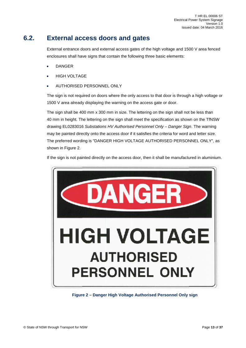
6.2. External access doors and gates External entrance doors and external access gates of the high voltage and 1500 V area fenced
enclosures shall have signs that contain the following three basic elements:
• DANGER
• HIGH VOLTAGE
• AUTHORISED PERSONNEL ONLY
The sign is not required on doors where the only access to that door is through a high voltage or
1500 V area already displaying the warning on the access gate or door.
The sign shall be 400 mm x 300 mm in size. The lettering on the sign shall not be less than
40 mm in height. The lettering on the sign shall meet the specification as shown on the TfNSW
drawing EL0283016 Substations HV Authorised Personnel Only – Danger Sign. The warning
may be painted directly onto the access door if it satisfies the criteria for word and letter size.
The preferred wording is "DANGER HIGH VOLTAGE AUTHORISED PERSONNEL ONLY", as
shown in Figure 2.
If the sign is not painted directly on the access door, then it shall be manufactured in aluminium.
Figure 2 – Danger High Voltage Authorised Personnel Only sign
© State of NSW through Transport for NSW Page 13 of 37
T HR EL 00006 ST Electrical Power System Signage
Version 1.0 Issued date: 04 March 2016
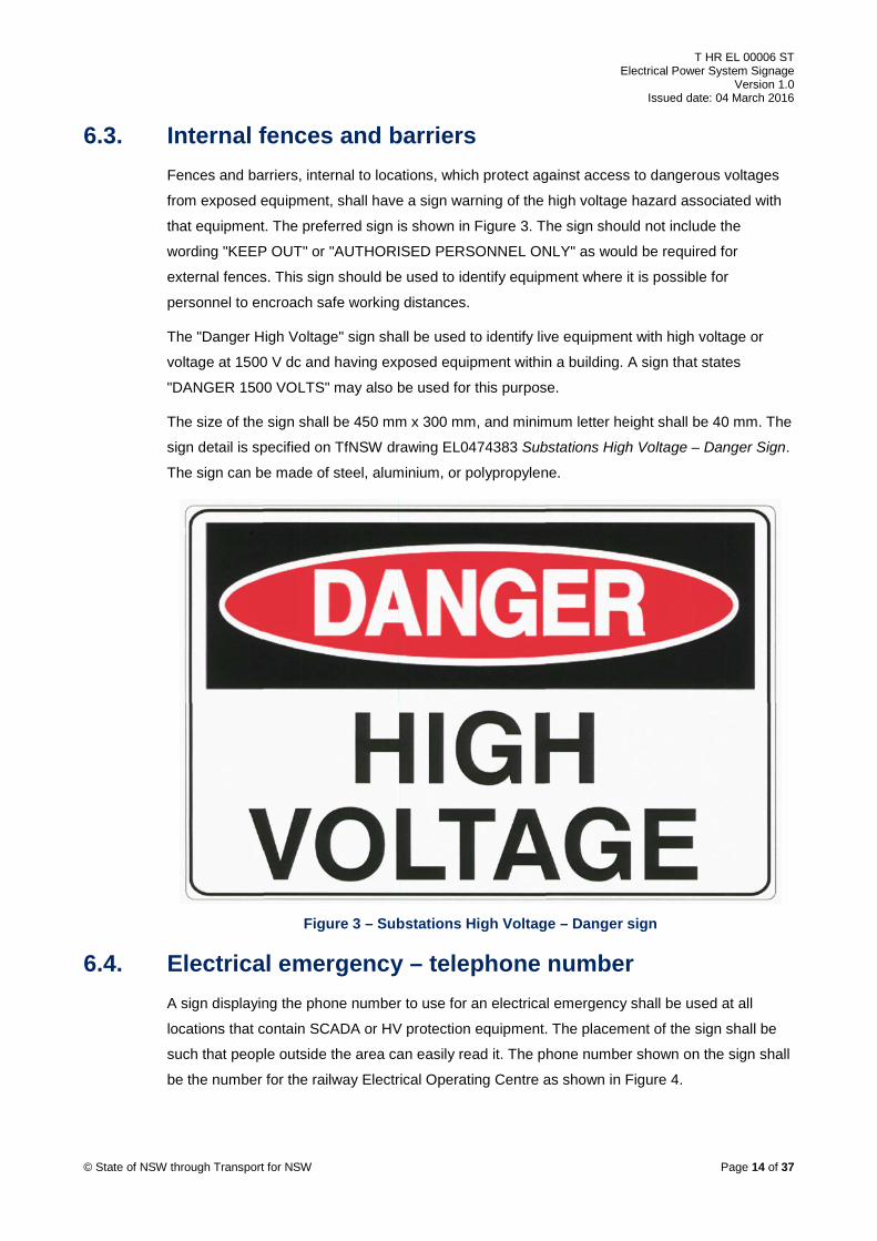
6.3. Internal fences and barriers Fences and barriers, internal to locations, which protect against access to dangerous voltages
from exposed equipment, shall have a sign warning of the high voltage hazard associated with
that equipment. The preferred sign is shown in Figure 3. The sign should not include the
wording "KEEP OUT" or "AUTHORISED PERSONNEL ONLY" as would be required for
external fences. This sign should be used to identify equipment where it is possible for
personnel to encroach safe working distances.
The "Danger High Voltage" sign shall be used to identify live equipment with high voltage or
voltage at 1500 V dc and having exposed equipment within a building. A sign that states
"DANGER 1500 VOLTS" may also be used for this purpose.
The size of the sign shall be 450 mm x 300 mm, and minimum letter height shall be 40 mm. The
sign detail is specified on TfNSW drawing EL0474383 Substations High Voltage – Danger Sign.
The sign can be made of steel, aluminium, or polypropylene.
Figure 3 – Substations High Voltage – Danger sign
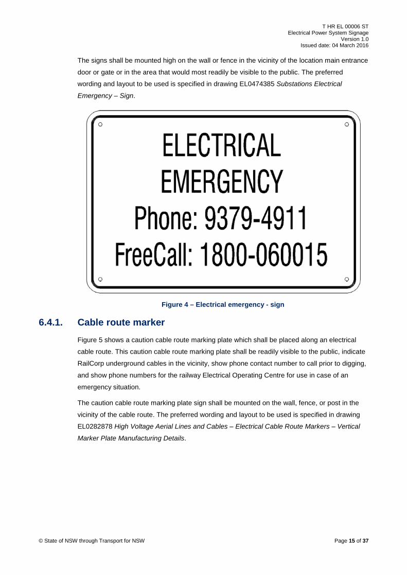
6.4. Electrical emergency – telephone number A sign displaying the phone number to use for an electrical emergency shall be used at all
locations that contain SCADA or HV protection equipment. The placement of the sign shall be
such that people outside the area can easily read it. The phone number shown on the sign shall
be the number for the railway Electrical Operating Centre as shown in Figure 4.
© State of NSW through Transport for NSW Page 14 of 37
T HR EL 00006 ST Electrical Power System Signage
Version 1.0 Issued date: 04 March 2016
The signs shall be mounted high on the wall or fence in the vicinity of the location main entrance
door or gate or in the area that would most readily be visible to the public. The preferred
wording and layout to be used is specified in drawing EL0474385 Substations Electrical
Emergency – Sign.
Figure 4 – Electrical emergency - sign
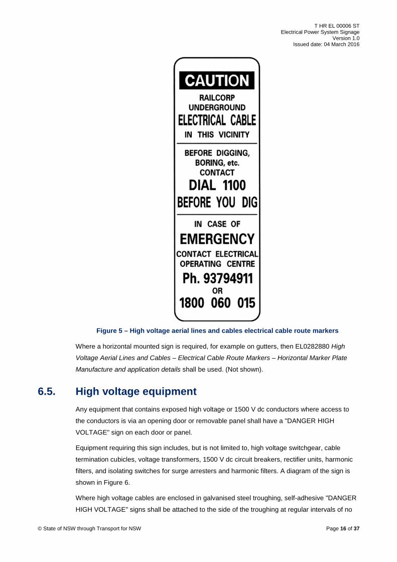
6.4.1. Cable route marker Figure 5 shows a caution cable route marking plate which shall be placed along an electrical
cable route. This caution cable route marking plate shall be readily visible to the public, indicate
RailCorp underground cables in the vicinity, show phone contact number to call prior to digging,
and show phone numbers for the railway Electrical Operating Centre for use in case of an
emergency situation.
The caution cable route marking plate sign shall be mounted on the wall, fence, or post in the
vicinity of the cable route. The preferred wording and layout to be used is specified in drawing
EL0282878 High Voltage Aerial Lines and Cables – Electrical Cable Route Markers – Vertical
Marker Plate Manufacturing Details.
© State of NSW through Transport for NSW Page 15 of 37
T HR EL 00006 ST Electrical Power System Signage
Version 1.0 Issued date: 04 March 2016
Figure 5 – High voltage aerial lines and cables electrical cable route markers
Where a horizontal mounted sign is required, for example on gutters, then EL0282880 High
Voltage Aerial Lines and Cables – Electrical Cable Route Markers – Horizontal Marker Plate
Manufacture and application details shall be used. (Not shown).
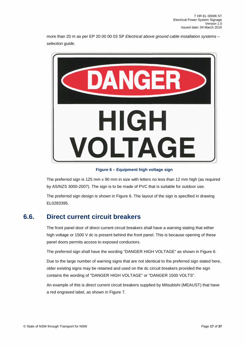
6.5. High voltage equipment Any equipment that contains exposed high voltage or 1500 V dc conductors where access to
the conductors is via an opening door or removable panel shall have a "DANGER HIGH
VOLTAGE" sign on each door or panel.
Equipment requiring this sign includes, but is not limited to, high voltage switchgear, cable
termination cubicles, voltage transformers, 1500 V dc circuit breakers, rectifier units, harmonic
filters, and isolating switches for surge arresters and harmonic filters. A diagram of the sign is
shown in Figure 6.
Where high voltage cables are enclosed in galvanised steel troughing, self-adhesive "DANGER
HIGH VOLTAGE" signs shall be attached to the side of the troughing at regular intervals of no
© State of NSW through Transport for NSW Page 16 of 37
T HR EL 00006 ST Electrical Power System Signage
Version 1.0 Issued date: 04 March 2016
more than 20 m as per EP 20 00 00 03 SP Electrical above ground cable installation systems –
selection guide.
Figure 6 – Equipment high voltage sign
The preferred sign is 125 mm x 90 mm in size with letters no less than 12 mm high (as required
by AS/NZS 3000-2007). The sign is to be made of PVC that is suitable for outdoor use.
The preferred sign design is shown in Figure 6. The layout of the sign is specified in drawing
EL0283395.
6.6. Direct current circuit breakers The front panel door of direct current circuit breakers shall have a warning stating that either
high voltage or 1500 V dc is present behind the front panel. This is because opening of these
panel doors permits access to exposed conductors.
The preferred sign shall have the wording "DANGER HIGH VOLTAGE" as shown in Figure 6.
Due to the large number of warning signs that are not identical to the preferred sign stated here,
older existing signs may be retained and used on the dc circuit breakers provided the sign
contains the wording of "DANGER HIGH VOLTAGE" or "DANGER 1500 VOLTS".
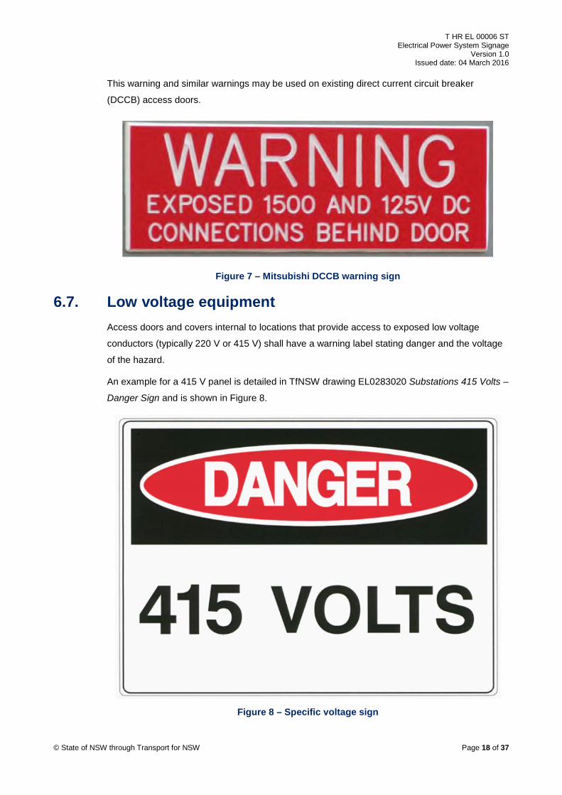
An example of this is direct current circuit breakers supplied by Mitsubishi (MEAUST) that have
a red engraved label, as shown in Figure 7.
© State of NSW through Transport for NSW Page 17 of 37
T HR EL 00006 ST Electrical Power System Signage
Version 1.0 Issued date: 04 March 2016
This warning and similar warnings may be used on existing direct current circuit breaker
(DCCB) access doors.
Figure 7 – Mitsubishi DCCB warning sign
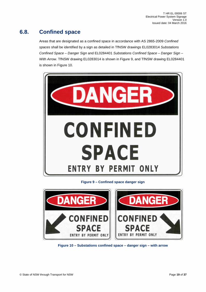
6.7. Low voltage equipment Access doors and covers internal to locations that provide access to exposed low voltage
conductors (typically 220 V or 415 V) shall have a warning label stating danger and the voltage
of the hazard.
An example for a 415 V panel is detailed in TfNSW drawing EL0283020 Substations 415 Volts –
Danger Sign and is shown in Figure 8.
Figure 8 – Specific voltage sign
© State of NSW through Transport for NSW Page 18 of 37
T HR EL 00006 ST Electrical Power System Signage
Version 1.0 Issued date: 04 March 2016
6.8. Confined space Areas that are designated as a confined space in accordance with AS 2865-2009 Confined
spaces shall be identified by a sign as detailed in TfNSW drawings EL0283014 Substations
Confined Space – Danger Sign and EL0284401 Substations Confined Space – Danger Sign –
With Arrow. TfNSW drawing EL0283014 is shown in Figure 9, and TfNSW drawing EL0284401
is shown in Figure 10.
Figure 9 – Confined space danger sign
Figure 10 – Substations confined space – danger sign – with arrow
© State of NSW through Transport for NSW Page 19 of 37
T HR EL 00006 ST Electrical Power System Signage
Version 1.0 Issued date: 04 March 2016
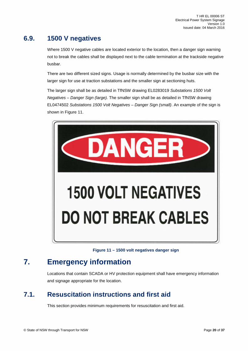
6.9. 1500 V negatives Where 1500 V negative cables are located exterior to the location, then a danger sign warning
not to break the cables shall be displayed next to the cable termination at the trackside negative
busbar.
There are two different sized signs. Usage is normally determined by the busbar size with the
larger sign for use at traction substations and the smaller sign at sectioning huts.
The larger sign shall be as detailed in TfNSW drawing EL0283019 Substations 1500 Volt
Negatives – Danger Sign (large). The smaller sign shall be as detailed in TfNSW drawing
EL0474502 Substations 1500 Volt Negatives – Danger Sign (small). An example of the sign is
shown in Figure 11.
Figure 11 – 1500 volt negatives danger sign
7. Emergency information Locations that contain SCADA or HV protection equipment shall have emergency information
and signage appropriate for the location.
7.1. Resuscitation instructions and first aid This section provides minimum requirements for resuscitation and first aid.
© State of NSW through Transport for NSW Page 20 of 37
T HR EL 00006 ST Electrical Power System Signage
Version 1.0 Issued date: 04 March 2016
7.1.1. Resuscitation instructions
Resuscitation instructions shall be prominently displayed in the location. Any chart may be
used, provided that the information displayed reflects the current methods in which personnel
are trained.
Charts should be sourced from organisations like St Johns Ambulance. A chart having
dimensions of 400 mm x 285 mm is preferred.
Charts with out-dated methods shall be replaced with up-to-date charts. This is to ensure that
the information displayed is current practice.
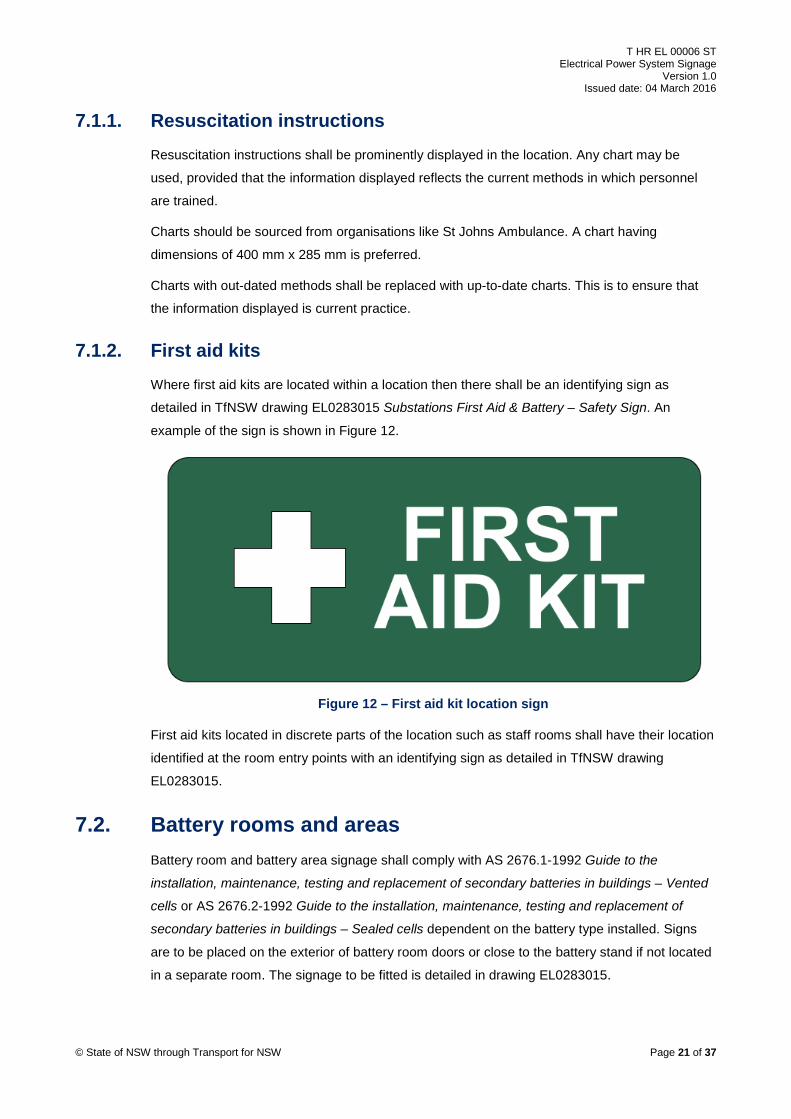
7.1.2. First aid kits Where first aid kits are located within a location then there shall be an identifying sign as
detailed in TfNSW drawing EL0283015 Substations First Aid & Battery – Safety Sign. An
example of the sign is shown in Figure 12.
Figure 12 – First aid kit location sign
First aid kits located in discrete parts of the location such as staff rooms shall have their location
identified at the room entry points with an identifying sign as detailed in TfNSW drawing
EL0283015.
7.2. Battery rooms and areas Battery room and battery area signage shall comply with AS 2676.1-1992 Guide to the
installation, maintenance, testing and replacement of secondary batteries in buildings – Vented
cells or AS 2676.2-1992 Guide to the installation, maintenance, testing and replacement of
secondary batteries in buildings – Sealed cells dependent on the battery type installed. Signs
are to be placed on the exterior of battery room doors or close to the battery stand if not located
in a separate room. The signage to be fitted is detailed in drawing EL0283015.
© State of NSW through Transport for NSW Page 21 of 37
T HR EL 00006 ST Electrical Power System Signage
Version 1.0 Issued date: 04 March 2016
For vented cells there are three aspects that are required:
• a regulatory sign stating the "Risk of battery explosion", "NO Smoking, Sparks, Flames"
• a sign displaying emergency information for the treatment of electrolyte burns
• emergency eyewash, shower, first aid, and safety signage
For sealed cells there are two aspects that are required:
• a regulatory sign stating the 'Risk of battery explosion", "NO Smoking, Sparks, Flames"
• first aid and safety signage
Figure 13 shows the preferred regulatory sign stating the "Risk of battery explosion", "NO
Smoking, Sparks, Flames".
Figure 13 – Risk of battery explosion sign
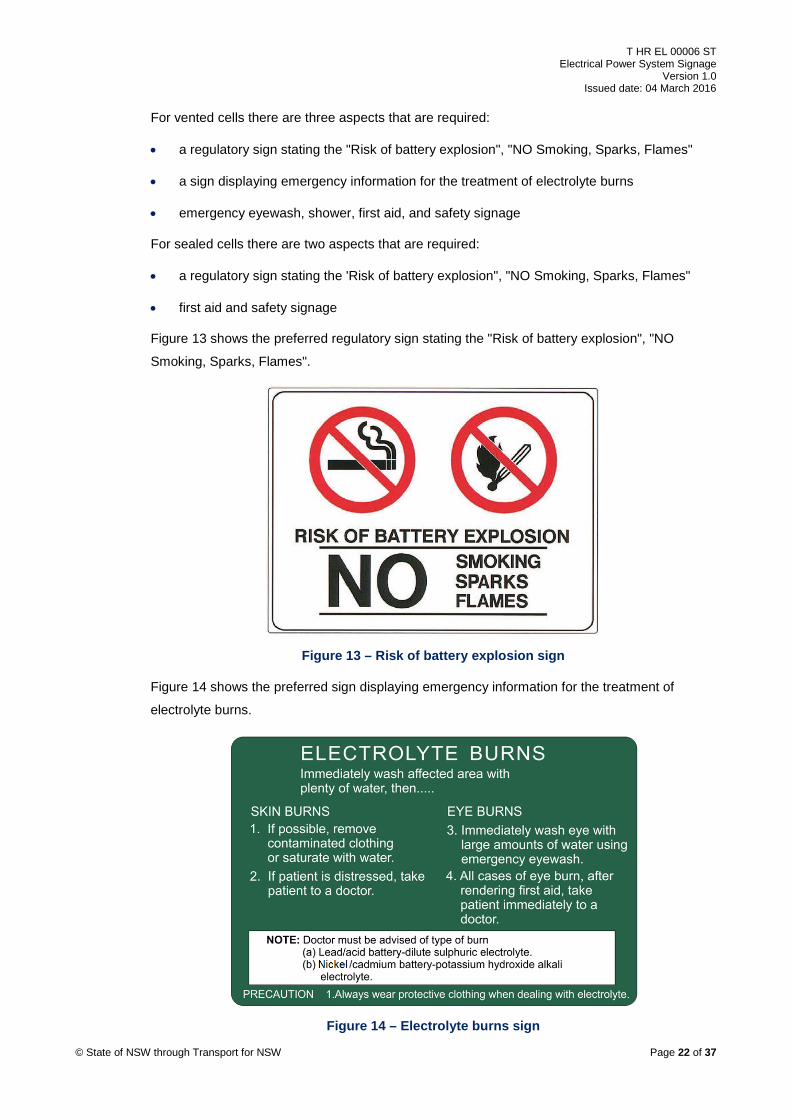
Figure 14 shows the preferred sign displaying emergency information for the treatment of
electrolyte burns.
Figure 14 – Electrolyte burns sign © State of NSW through Transport for NSW Page 22 of 37
T HR EL 00006 ST Electrical Power System Signage
Version 1.0 Issued date: 04 March 2016
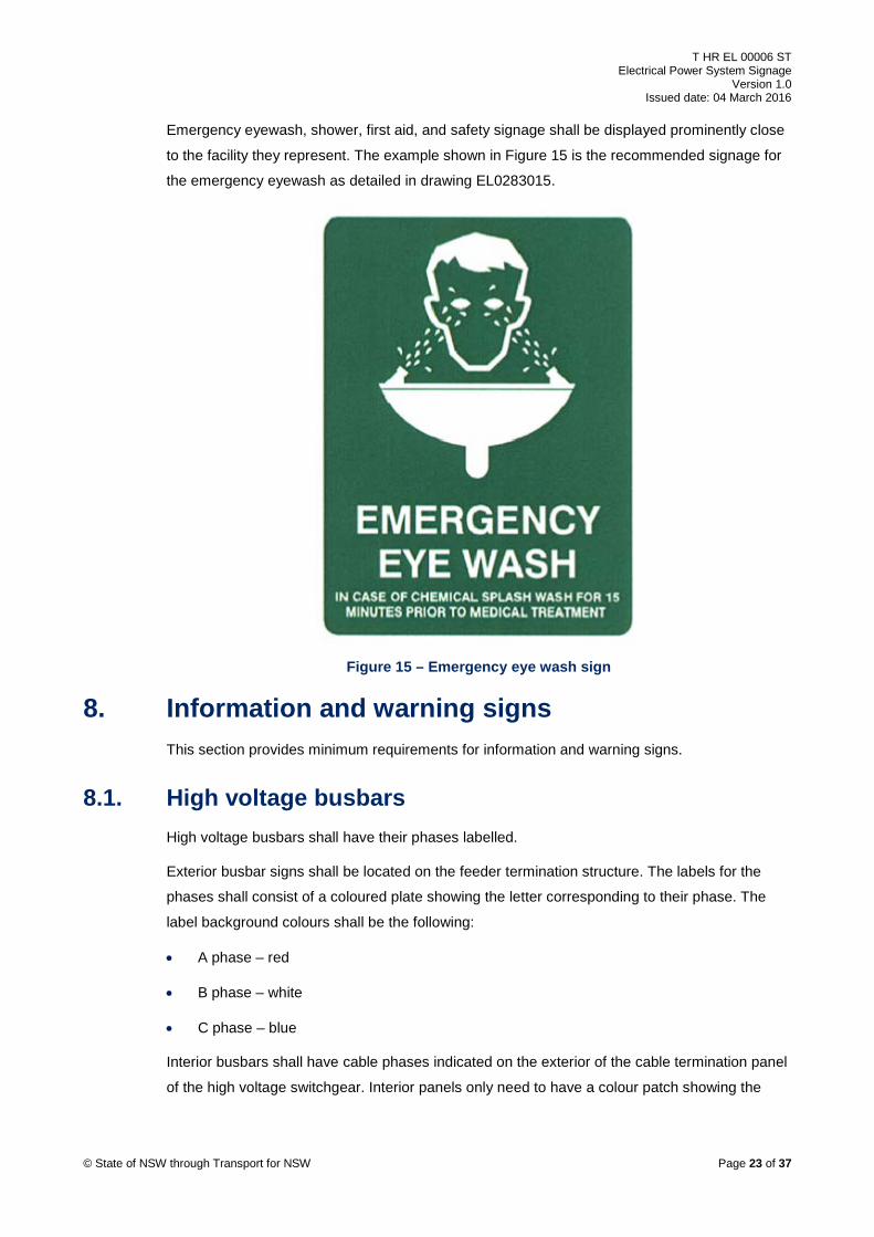
Emergency eyewash, shower, first aid, and safety signage shall be displayed prominently close
to the facility they represent. The example shown in Figure 15 is the recommended signage for
the emergency eyewash as detailed in drawing EL0283015.
Figure 15 – Emergency eye wash sign
8. Information and warning signs This section provides minimum requirements for information and warning signs.
8.1. High voltage busbars High voltage busbars shall have their phases labelled.
Exterior busbar signs shall be located on the feeder termination structure. The labels for the
phases shall consist of a coloured plate showing the letter corresponding to their phase. The
label background colours shall be the following:
• A phase – red
• B phase – white
• C phase – blue
Interior busbars shall have cable phases indicated on the exterior of the cable termination panel
of the high voltage switchgear. Interior panels only need to have a colour patch showing the
© State of NSW through Transport for NSW Page 23 of 37
T HR EL 00006 ST Electrical Power System Signage
Version 1.0 Issued date: 04 March 2016
phase. Cables are to be identified with their phases so they can still be identified if the
termination panel cover is removed.
There is no drawing for these signs.
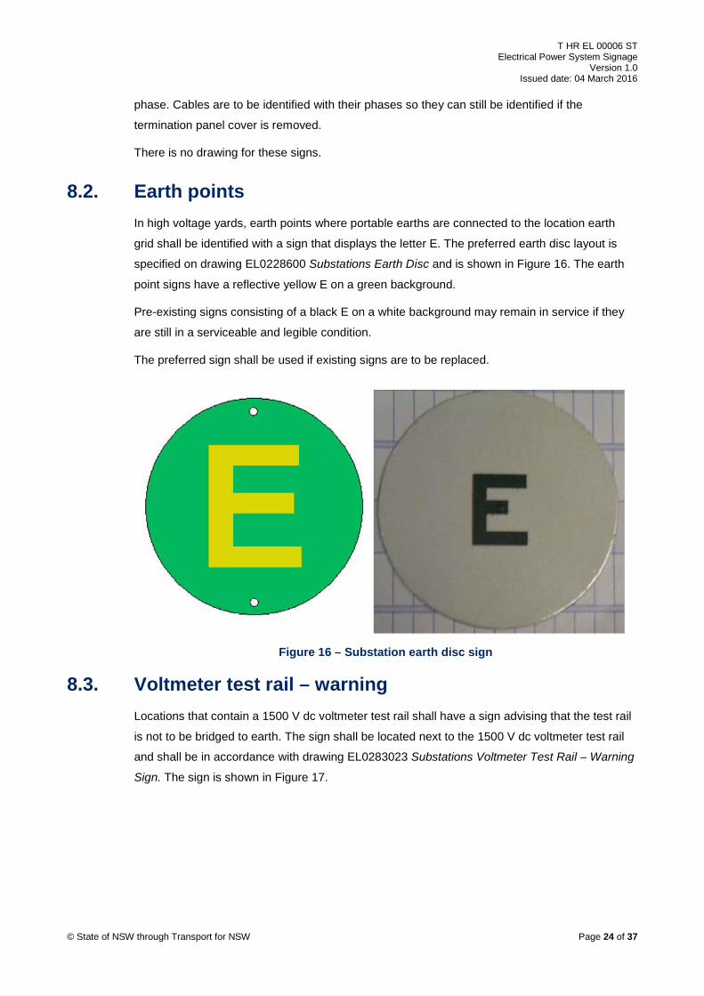
8.2. Earth points In high voltage yards, earth points where portable earths are connected to the location earth
grid shall be identified with a sign that displays the letter E. The preferred earth disc layout is
specified on drawing EL0228600 Substations Earth Disc and is shown in Figure 16. The earth
point signs have a reflective yellow E on a green background.
Pre-existing signs consisting of a black E on a white background may remain in service if they
are still in a serviceable and legible condition.
The preferred sign shall be used if existing signs are to be replaced.
Figure 16 – Substation earth disc sign
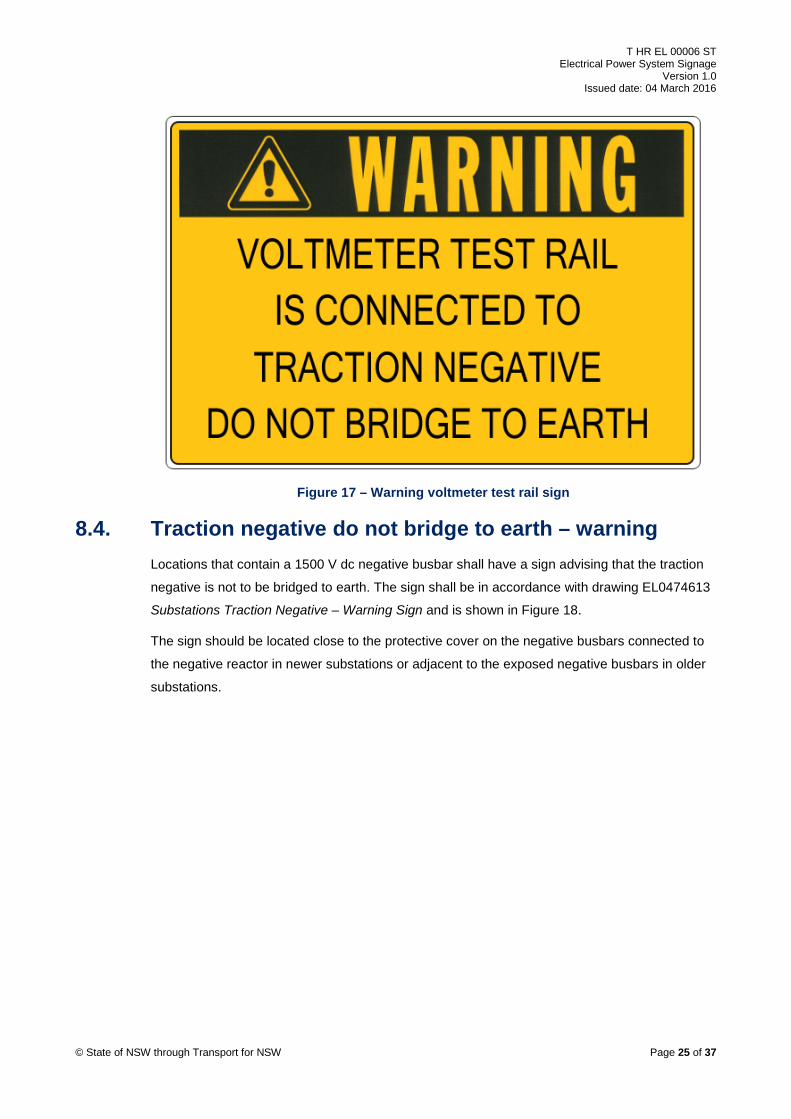
8.3. Voltmeter test rail – warning Locations that contain a 1500 V dc voltmeter test rail shall have a sign advising that the test rail
is not to be bridged to earth. The sign shall be located next to the 1500 V dc voltmeter test rail
and shall be in accordance with drawing EL0283023 Substations Voltmeter Test Rail – Warning
Sign. The sign is shown in Figure 17.
© State of NSW through Transport for NSW Page 24 of 37
T HR EL 00006 ST Electrical Power System Signage
Version 1.0 Issued date: 04 March 2016
Figure 17 – Warning voltmeter test rail sign
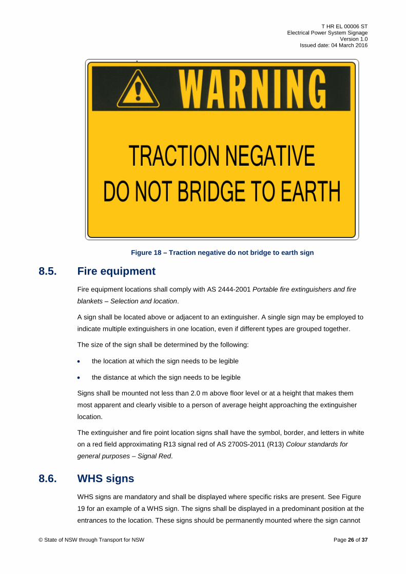
8.4. Traction negative do not bridge to earth – warning Locations that contain a 1500 V dc negative busbar shall have a sign advising that the traction
negative is not to be bridged to earth. The sign shall be in accordance with drawing EL0474613
Substations Traction Negative – Warning Sign and is shown in Figure 18.
The sign should be located close to the protective cover on the negative busbars connected to
the negative reactor in newer substations or adjacent to the exposed negative busbars in older
substations.
© State of NSW through Transport for NSW Page 25 of 37
T HR EL 00006 ST Electrical Power System Signage
Version 1.0 Issued date: 04 March 2016
Figure 18 – Traction negative do not bridge to earth sign
8.5. Fire equipment Fire equipment locations shall comply with AS 2444-2001 Portable fire extinguishers and fire
blankets – Selection and location.
A sign shall be located above or adjacent to an extinguisher. A single sign may be employed to
indicate multiple extinguishers in one location, even if different types are grouped together.
The size of the sign shall be determined by the following:
• the location at which the sign needs to be legible
• the distance at which the sign needs to be legible
Signs shall be mounted not less than 2.0 m above floor level or at a height that makes them
most apparent and clearly visible to a person of average height approaching the extinguisher
location.
The extinguisher and fire point location signs shall have the symbol, border, and letters in white
on a red field approximating R13 signal red of AS 2700S-2011 (R13) Colour standards for
general purposes – Signal Red.
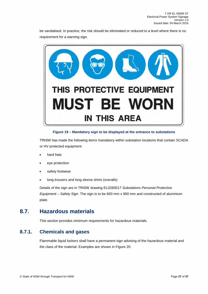
8.6. WHS signs WHS signs are mandatory and shall be displayed where specific risks are present. See Figure
19 for an example of a WHS sign. The signs shall be displayed in a predominant position at the
entrances to the location. These signs should be permanently mounted where the sign cannot
© State of NSW through Transport for NSW Page 26 of 37
T HR EL 00006 ST Electrical Power System Signage
Version 1.0 Issued date: 04 March 2016
be vandalised. In practice, the risk should be eliminated or reduced to a level where there is no
requirement for a warning sign.
Figure 19 – Mandatory sign to be displayed at the entrance to substations
TfNSW has made the following items mandatory within substation locations that contain SCADA
or HV protected equipment:
• hard hats
• eye protection
• safety footwear
• long trousers and long sleeve shirts (overalls)
Details of the sign are in TfNSW drawing EL0283017 Substations Personal Protective
Equipment – Safety Sign. The sign is to be 600 mm x 900 mm and constructed of aluminium
plate.
8.7. Hazardous materials This section provides minimum requirements for hazardous materials.
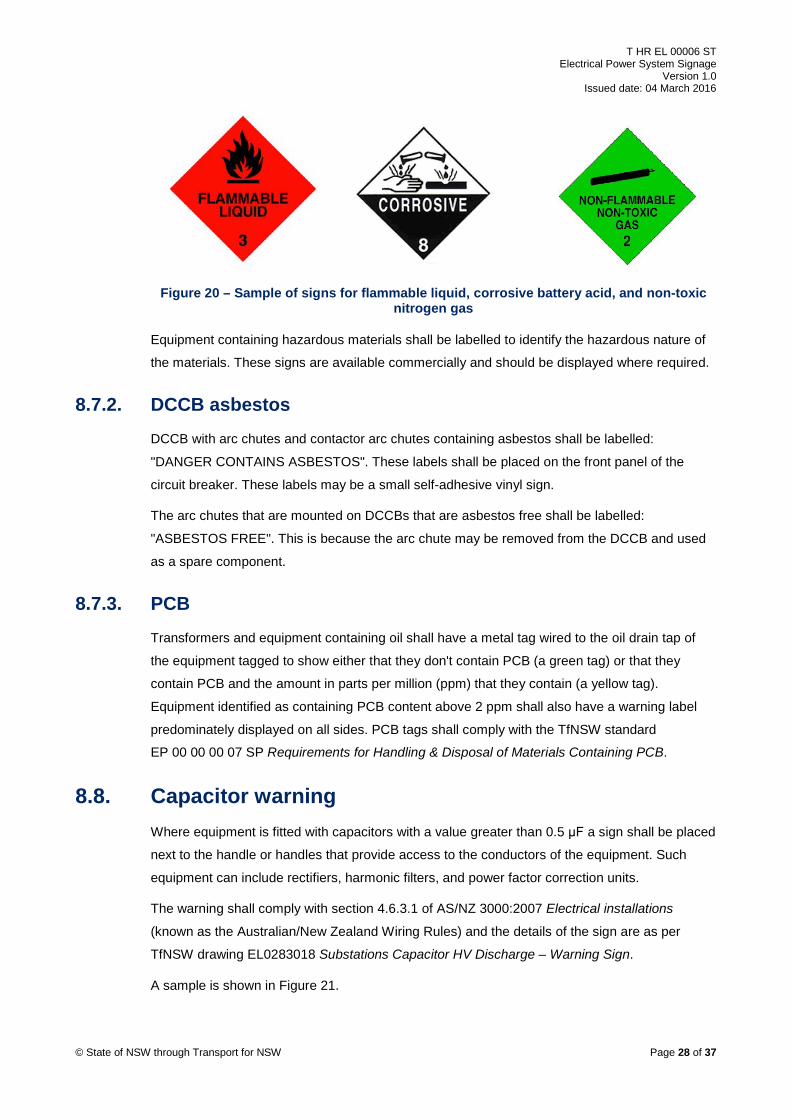
8.7.1. Chemicals and gases
Flammable liquid lockers shall have a permanent sign advising of the hazardous material and
the class of the material. Examples are shown in Figure 20.
© State of NSW through Transport for NSW Page 27 of 37
T HR EL 00006 ST Electrical Power System Signage
Version 1.0 Issued date: 04 March 2016
Figure 20 – Sample of signs for flammable liquid, corrosive battery acid, and non-toxic nitrogen gas
Equipment containing hazardous materials shall be labelled to identify the hazardous nature of
the materials. These signs are available commercially and should be displayed where required.
8.7.2. DCCB asbestos DCCB with arc chutes and contactor arc chutes containing asbestos shall be labelled:
"DANGER CONTAINS ASBESTOS". These labels shall be placed on the front panel of the
circuit breaker. These labels may be a small self-adhesive vinyl sign.
The arc chutes that are mounted on DCCBs that are asbestos free shall be labelled:
"ASBESTOS FREE". This is because the arc chute may be removed from the DCCB and used
as a spare component.
8.7.3. PCB Transformers and equipment containing oil shall have a metal tag wired to the oil drain tap of
the equipment tagged to show either that they don't contain PCB (a green tag) or that they
contain PCB and the amount in parts per million (ppm) that they contain (a yellow tag).
Equipment identified as containing PCB content above 2 ppm shall also have a warning label
predominately displayed on all sides. PCB tags shall comply with the TfNSW standard
EP 00 00 00 07 SP Requirements for Handling & Disposal of Materials Containing PCB.
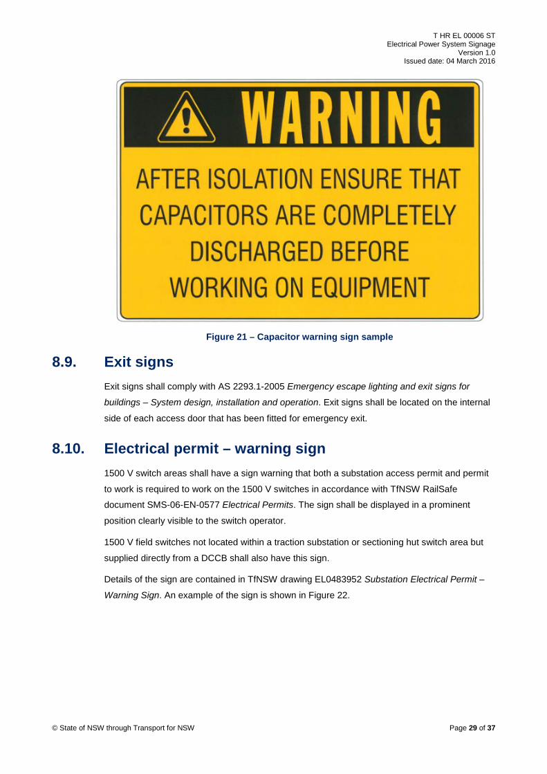
8.8. Capacitor warning Where equipment is fitted with capacitors with a value greater than 0.5 μF a sign shall be placed
next to the handle or handles that provide access to the conductors of the equipment. Such
equipment can include rectifiers, harmonic filters, and power factor correction units.
The warning shall comply with section 4.6.3.1 of AS/NZ 3000:2007 Electrical installations
(known as the Australian/New Zealand Wiring Rules) and the details of the sign are as per
TfNSW drawing EL0283018 Substations Capacitor HV Discharge – Warning Sign.
A sample is shown in Figure 21.
© State of NSW through Transport for NSW Page 28 of 37
T HR EL 00006 ST Electrical Power System Signage
Version 1.0 Issued date: 04 March 2016
Figure 21 – Capacitor warning sign sample
8.9. Exit signs Exit signs shall comply with AS 2293.1-2005 Emergency escape lighting and exit signs for
buildings – System design, installation and operation. Exit signs shall be located on the internal
side of each access door that has been fitted for emergency exit.
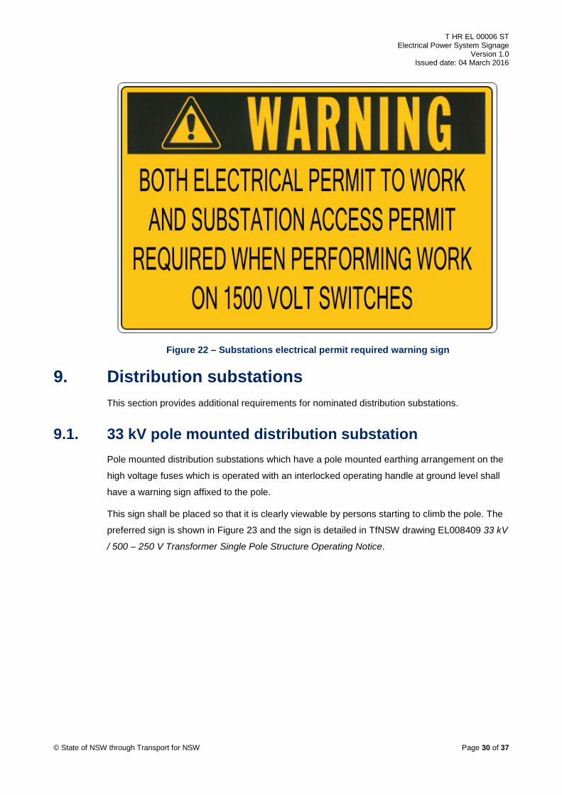
8.10. Electrical permit – warning sign 1500 V switch areas shall have a sign warning that both a substation access permit and permit
to work is required to work on the 1500 V switches in accordance with TfNSW RailSafe
document SMS-06-EN-0577 Electrical Permits. The sign shall be displayed in a prominent
position clearly visible to the switch operator.
1500 V field switches not located within a traction substation or sectioning hut switch area but
supplied directly from a DCCB shall also have this sign.
Details of the sign are contained in TfNSW drawing EL0483952 Substation Electrical Permit –
Warning Sign. An example of the sign is shown in Figure 22.
© State of NSW through Transport for NSW Page 29 of 37
T HR EL 00006 ST Electrical Power System Signage
Version 1.0 Issued date: 04 March 2016
Figure 22 – Substations electrical permit required warning sign
9. Distribution substations This section provides additional requirements for nominated distribution substations.
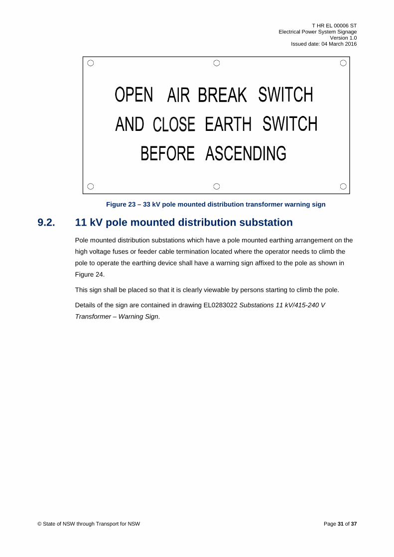
9.1. 33 kV pole mounted distribution substation Pole mounted distribution substations which have a pole mounted earthing arrangement on the
high voltage fuses which is operated with an interlocked operating handle at ground level shall
have a warning sign affixed to the pole.
This sign shall be placed so that it is clearly viewable by persons starting to climb the pole. The
preferred sign is shown in Figure 23 and the sign is detailed in TfNSW drawing EL008409 33 kV
/ 500 – 250 V Transformer Single Pole Structure Operating Notice.
© State of NSW through Transport for NSW Page 30 of 37
T HR EL 00006 ST Electrical Power System Signage
Version 1.0 Issued date: 04 March 2016
Figure 23 – 33 kV pole mounted distribution transformer warning sign
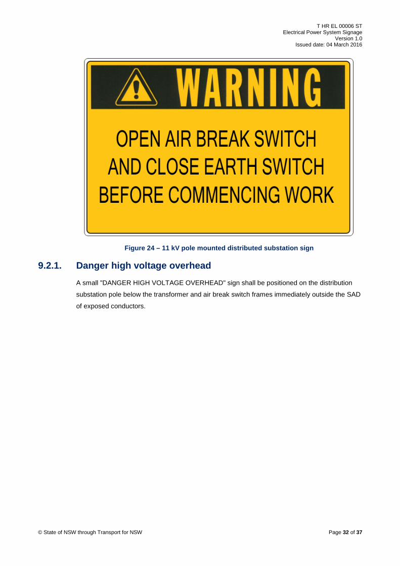
9.2. 11 kV pole mounted distribution substation Pole mounted distribution substations which have a pole mounted earthing arrangement on the
high voltage fuses or feeder cable termination located where the operator needs to climb the
pole to operate the earthing device shall have a warning sign affixed to the pole as shown in
Figure 24.
This sign shall be placed so that it is clearly viewable by persons starting to climb the pole.
Details of the sign are contained in drawing EL0283022 Substations 11 kV/415-240 V
Transformer – Warning Sign.
© State of NSW through Transport for NSW Page 31 of 37
T HR EL 00006 ST Electrical Power System Signage
Version 1.0 Issued date: 04 March 2016
Figure 24 – 11 kV pole mounted distributed substation sign
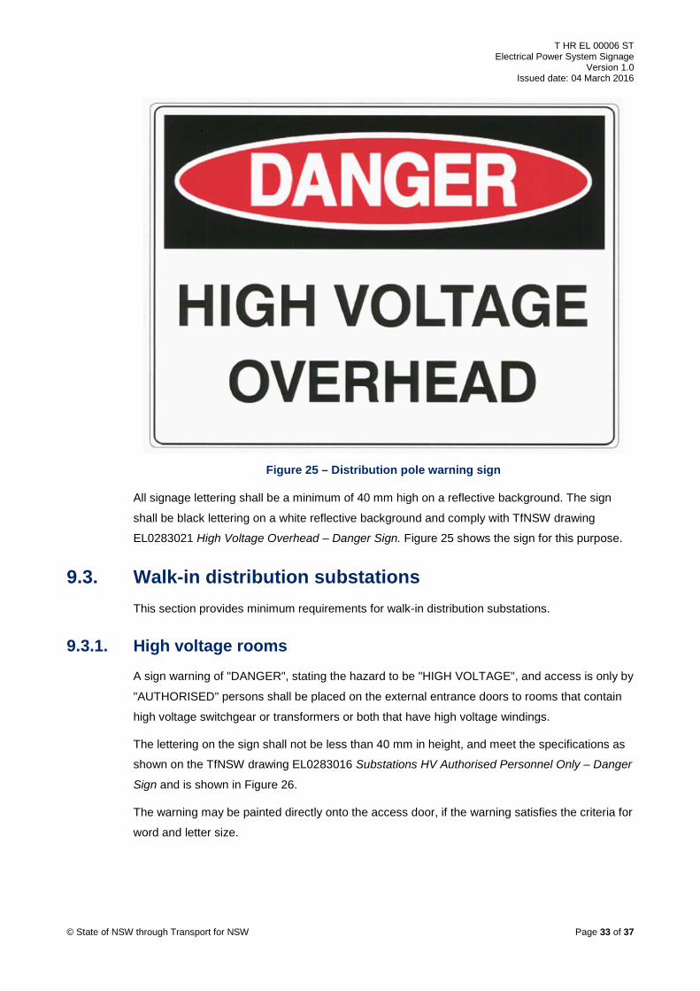
9.2.1. Danger high voltage overhead A small "DANGER HIGH VOLTAGE OVERHEAD" sign shall be positioned on the distribution
substation pole below the transformer and air break switch frames immediately outside the SAD
of exposed conductors.
© State of NSW through Transport for NSW Page 32 of 37
T HR EL 00006 ST Electrical Power System Signage
Version 1.0 Issued date: 04 March 2016
Figure 25 – Distribution pole warning sign
All signage lettering shall be a minimum of 40 mm high on a reflective background. The sign
shall be black lettering on a white reflective background and comply with TfNSW drawing
EL0283021 High Voltage Overhead – Danger Sign. Figure 25 shows the sign for this purpose.
9.3. Walk-in distribution substations This section provides minimum requirements for walk-in distribution substations.
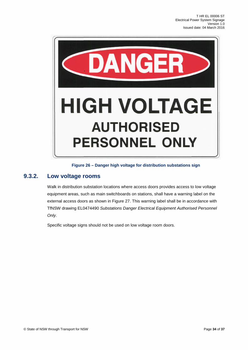
9.3.1. High voltage rooms A sign warning of "DANGER", stating the hazard to be "HIGH VOLTAGE", and access is only by
"AUTHORISED" persons shall be placed on the external entrance doors to rooms that contain
high voltage switchgear or transformers or both that have high voltage windings.
The lettering on the sign shall not be less than 40 mm in height, and meet the specifications as
shown on the TfNSW drawing EL0283016 Substations HV Authorised Personnel Only – Danger
Sign and is shown in Figure 26.
The warning may be painted directly onto the access door, if the warning satisfies the criteria for
word and letter size.
© State of NSW through Transport for NSW Page 33 of 37
T HR EL 00006 ST Electrical Power System Signage
Version 1.0 Issued date: 04 March 2016
Figure 26 – Danger high voltage for distribution substations sign
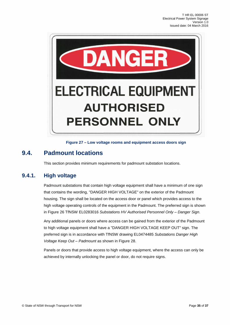
9.3.2. Low voltage rooms Walk in distribution substation locations where access doors provides access to low voltage
equipment areas, such as main switchboards on stations, shall have a warning label on the
external access doors as shown in Figure 27. This warning label shall be in accordance with
TfNSW drawing EL0474490 Substations Danger Electrical Equipment Authorised Personnel
Only.
Specific voltage signs should not be used on low voltage room doors.
© State of NSW through Transport for NSW Page 34 of 37
T HR EL 00006 ST Electrical Power System Signage
Version 1.0 Issued date: 04 March 2016
Figure 27 – Low voltage rooms and equipment access doors sign
9.4. Padmount locations This section provides minimum requirements for padmount substation locations.
9.4.1. High voltage Padmount substations that contain high voltage equipment shall have a minimum of one sign
that contains the wording, "DANGER HIGH VOLTAGE" on the exterior of the Padmount
housing. The sign shall be located on the access door or panel which provides access to the
high voltage operating controls of the equipment in the Padmount. The preferred sign is shown
in Figure 26 TfNSW EL0283016 Substations HV Authorised Personnel Only – Danger Sign.
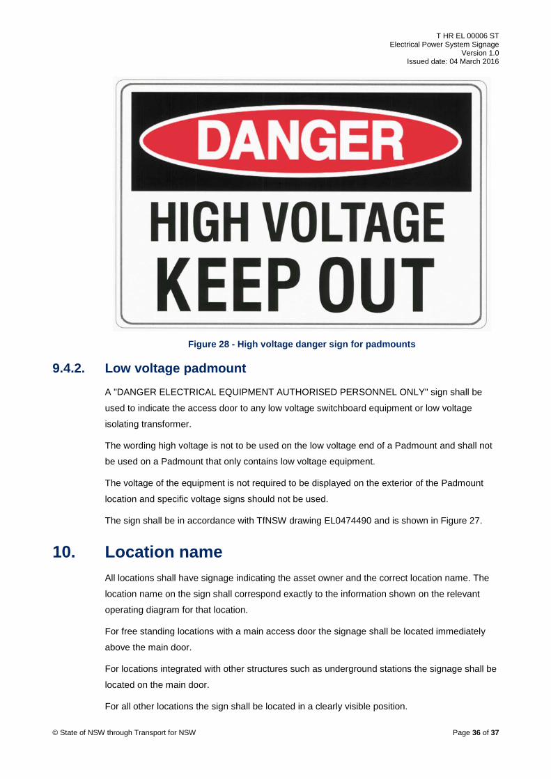
Any additional panels or doors where access can be gained from the exterior of the Padmount
to high voltage equipment shall have a "DANGER HIGH VOLTAGE KEEP OUT" sign. The
preferred sign is in accordance with TfNSW drawing EL0474485 Substations Danger High
Voltage Keep Out – Padmount as shown in Figure 28.
Panels or doors that provide access to high voltage equipment, where the access can only be
achieved by internally unlocking the panel or door, do not require signs.
© State of NSW through Transport for NSW Page 35 of 37
T HR EL 00006 ST Electrical Power System Signage
Version 1.0 Issued date: 04 March 2016
Figure 28 - High voltage danger sign for padmounts
9.4.2. Low voltage padmount A "DANGER ELECTRICAL EQUIPMENT AUTHORISED PERSONNEL ONLY" sign shall be
used to indicate the access door to any low voltage switchboard equipment or low voltage
isolating transformer.
The wording high voltage is not to be used on the low voltage end of a Padmount and shall not
be used on a Padmount that only contains low voltage equipment.
The voltage of the equipment is not required to be displayed on the exterior of the Padmount
location and specific voltage signs should not be used.
The sign shall be in accordance with TfNSW drawing EL0474490 and is shown in Figure 27.
10. Location name All locations shall have signage indicating the asset owner and the correct location name. The
location name on the sign shall correspond exactly to the information shown on the relevant
operating diagram for that location.
For free standing locations with a main access door the signage shall be located immediately
above the main door.
For locations integrated with other structures such as underground stations the signage shall be
located on the main door.
For all other locations the sign shall be located in a clearly visible position.
© State of NSW through Transport for NSW Page 36 of 37
T HR EL 00006 ST Electrical Power System Signage
Version 1.0 Issued date: 04 March 2016
The preferred location name sign shall be black lettering on a white background with lettering
40 mm in height and shall be fixed in the same manner as the warning signs at that location.
The location name at pole mounted substations is additional to the pole number as specified in
TfNSW high voltage (HV) aerial line standard EP 10 01 00 06 SP HV Aerial Line Standards for
Design and Construction.
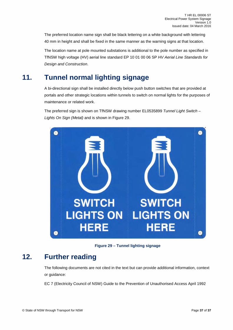
11. Tunnel normal lighting signage A bi-directional sign shall be installed directly below push button switches that are provided at
portals and other strategic locations within tunnels to switch on normal lights for the purposes of
maintenance or related work.
The preferred sign is shown on TfNSW drawing number EL0535899 Tunnel Light Switch –
Lights On Sign (Metal) and is shown in Figure 29.
Figure 29 – Tunnel lighting signage
12. Further reading The following documents are not cited in the text but can provide additional information, context
or guidance:
EC 7 (Electricity Council of NSW) Guide to the Prevention of Unauthorised Access April 1992
© State of NSW through Transport for NSW Page 37 of 37