Embed Size (px)
Citation preview
39
Electrical Power Quality and Utilisation, Journal Vol. XIV, No. 1, 2008
Voltage Quality Improvement Using DVRchellali BenachaiBa, Brahim FerdiBechar University Center, Algeria
Summary: the problem of voltage sags and swells and its severe impact on sensitive loads is well known. to solve this problem, custom power devices are used. one of those devices is the dynamic Voltage restorer (dVr), which is the most efficient and effective modern custom power device used in power distribution networks. its appeal includes lower cost, smaller size, and its fast dynamic response to the disturbance. this paper describes dVr principles and voltage restoration methods at the point of common coupling (Pcc). simulation results are presented to illustrate and understand the performances of dVr in load voltage compensation.
1. introduction
Power distribution systems, ideally, should provide their customers with an uninterrupted flow of energy at smooth sinusoidal voltage at the contracted magnitude level and frequency [1] however, in practice, power systems, especially the distribution systems, have numerous nonlinear loads, which significantly affect the quality of power supplies. As a result of the nonlinear loads, the purity of the waveform of supplies is lost. This ends up producing many power quality problems. Apart from nonlinear loads, some system events, both usual (e.g. capacitor switching, motor starling) and unusual (e.g. faults) could also inflict power quality problems [2]. Power quality is an issue that is becoming increasingly important to electricity consumers at all levels of usage. Sensitive equipment and non-linear loads are now more common place in both the industrial sectors and the domestic environment. Because of this a heightened awareness of power quality is developing amongst electricity users.
Faults at either the transmission or distribution level may cause transient voltage sag or swell in the entire system or a large part of it. Also, under heavy load conditions, a significant voltage drop may occur in the system. Voltage sags can occur at any instant of time, with amplitudes ranging from 10–90% and a duration lasting for half a cycle to one minute [3]. Further, they could be either balanced or unbalanced, depending on the type of fault and they could have unpredictable magnitudes, depending on factors such as distance from the fault and the transformer connections. Voltage swell, on the other hand, is defined as a sudden increasing of supply voltage up 110% to 180% in RMS voltage at the network fundamental frequency with duration from 10 ms to 1 minute [4]. Voltage swells are not as important as voltage sags because they are less common in distribution systems. Voltage sag and swell can cause sensitive equipment (such as found in semiconductor or chemical plants) to fail, or shutdown, as well as create a large current unbalance that could blow fuses or trip breakers. These effects can be very expensive for the customer, ranging from minor quality variations to production downtime and equipment damage [5].
There are many different methods to mitigate voltage sags and swells, but the use of a custom Power device is considered
to be the most efficient method. The concept of custom Power was introduced by N.G. Hingorani in 1995. Like Flexible AC Transmission Systems (FACTS) for transmission systems, the term custom power pertains to the use of power electronics controllers in a distribution system, especially, to deal with various power quality problems. Just as FACTS improves the power transfer capabilities and stability margins, custom power makes sure customers get pre-specified quality and reliability of supply. This pre-specified quality may contain a combination of specifications of the following [6]: low phase unbalance, no power interruptions, low flicker at the load voltage, low harmonic distortion in load voltage, magnitude and duration of overvoltages and undervoltages within specified limits, acceptance of fluctuations, and poor factor loads without significant effect on the terminal voltage.
There are many types of Custom Power devices. Some of these devices include: Active Power Filters (APF), Battery Energy Storage Systems (BESS), Distribution STATic synchronous COMpensators (DSTATCOM), Distribution Series Capacitors (DSC), Dynamic Voltage Restorer (DVR), Surge Arresters (SA), Super conducting Magnetic Energy Systems (SMES), Static Electronic Tap Changers (SETC), Solid-State Transfer Switches (SSTS), Solid State Fault Current Limiter (SSFCL), Static Var Compensator (SVC), Thyristor Switched Capacitors (TSC), and Uninterruptible Power Supplies (UPS) [7, 8].
Each of Custom Power devices has its own benefits and limitations. The most effective type of these devices is considered to be the Dynamic Voltage Restorer (DVR). There are numerous reasons why the DVR is preferred over the others. A few of these reasons are presented as follows. The SVC pre-dates the DVR, but the DVR is still preferred because the SVC has no ability to control active power flow [9]. Another reason is that the DVR costs less compared to the UPS [10, 11]. Not only the UPS is costly, it also requires a high level of maintenance because batteries leak and have to be replaced as often as every five years [11]. Other reasons include that the DVR has a higher energy capacity and lower costs compared to the SMES device [9]. Furthermore, the DVR is smaller in size and costs less compared to the DSTATCOM [9]. Based on these reasons, it is no surprise that the DVR is widely considered as an effective custom power device in mitigating voltage sags [12]. In addition to voltage
key words:Dynamic Voltage Restorer (DVR), voltage sags, voltage swells, custom power, power quality
Chellali Benachaiba and Brahim Ferdi: Voltage Quality Improvement Using DVR
40 Power Quality and Utilization, Journal • Vol. XIV, No 1, 2008
sags and swells compensation, DVR can also added other features such as harmonics and Power Factor correction. Compared to the other devices, the DVR clearly provides the best economic solution for its size and capabilities.
This paper Introduces Dynamic Voltage Restorer (DVR) and its operating principle. Then, analyses of the voltage compensation methods are presented. At the end, simulation results using MATLAB are illustrated and discussed.
2. dyNamic VolTage resTorer (dVr)
A Dynamic Voltage Restorer (DVR) is a recently proposed series connected solid state device that injects voltage into the system in order to regulate the load side voltage. The DVR was first installed in 1996 [12]. It is normally installed in a distribution system between the supply and the critical load feeder [13]. Its primary function is to rapidly boost up the load-side voltage in the event of a disturbance in order to avoid any power disruption to that load [11, 14]. There are various circuit topologies and control schemes that can be used to implement a DVR. In addition to voltage sags and swells compensation, DVR can also added other features such as: line voltage harmonics compensation, reduction of transients in voltage and fault current limitations.
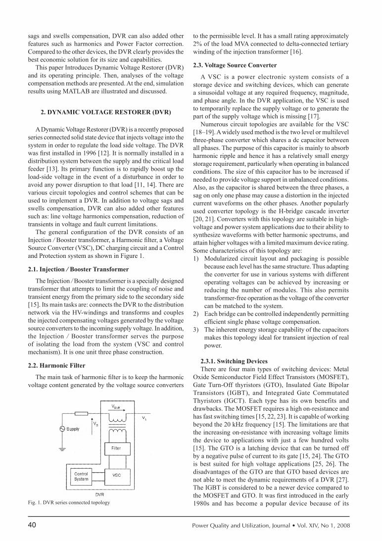
The general configuration of the DVR consists of an Injection / Booster transformer, a Harmonic filter, a Voltage Source Converter (VSC), DC charging circuit and a Control and Protection system as shown in Figure 1.
2.1. injection / Booster transformer
The Injection / Booster transformer is a specially designed transformer that attempts to limit the coupling of noise and transient energy from the primary side to the secondary side [15]. Its main tasks are: connects the DVR to the distribution network via the HV-windings and transforms and couples the injected compensating voltages generated by the voltage source converters to the incoming supply voltage. In addition, the Injection / Booster transformer serves the purpose of isolating the load from the system (VSC and control mechanism). It is one unit three phase construction.
2.2. harmonic Filter
The main task of harmonic filter is to keep the harmonic voltage content generated by the voltage source converters
to the permissible level. It has a small rating approximately 2% of the load MVA connected to delta-connected tertiary winding of the injection transformer [16].
2.3. Voltage source converter
A VSC is a power electronic system consists of a storage device and switching devices, which can generate a sinusoidal voltage at any required frequency, magnitude, and phase angle. In the DVR application, the VSC is used to temporarily replace the supply voltage or to generate the part of the supply voltage which is missing [17].
Numerous circuit topologies are available for the VSC [18–19]. A widely used method is the two level or multilevel three-phase converter which shares a dc capacitor between all phases. The purpose of this capacitor is mainly to absorb harmonic ripple and hence it has a relatively small energy storage requirement, particularly when operating in balanced conditions. The size of this capacitor has to be increased if needed to provide voltage support in unbalanced conditions. Also, as the capacitor is shared between the three phases, a sag on only one phase may cause a distortion in the injected current waveforms on the other phases. Another popularly used converter topology is the H-bridge cascade inverter [20, 21]. Converters with this topology are suitable in high-voltage and power system applications due to their ability to synthesize waveforms with better harmonic spectrums, and attain higher voltages with a limited maximum device rating. Some characteristics of this topology are:1) Modularized circuit layout and packaging is possible
because each level has the same structure. Thus adapting the converter for use in various systems with different operating voltages can be achieved by increasing or reducing the number of modules. This also permits transformer-free operation as the voltage of the converter can be matched to the system.
2) Each bridge can be controlled independently permitting efficient single phase voltage compensation.
3) The inherent energy storage capability of the capacitors makes this topology ideal for transient injection of real power.
2.3.1. switching devicesThere are four main types of switching devices: Metal
Oxide Semiconductor Field Effect Transistors (MOSFET), Gate Turn-Off thyristors (GTO), Insulated Gate Bipolar Transistors (IGBT), and Integrated Gate Commutated Thyristors (IGCT). Each type has its own benefits and drawbacks. The MOSFET requires a high on-resistance and has fast switching times [15, 22, 23]. It is capable of working beyond the 20 kHz frequency [15]. The limitations are that the increasing on-resistance with increasing voltage limits the device to applications with just a few hundred volts [15]. The GTO is a latching device that can be turned off by a negative pulse of current to its gate [15, 24]. The GTO is best suited for high voltage applications [25, 26]. The disadvantages of the GTO are that GTO based devices are not able to meet the dynamic requirements of a DVR [27]. The IGBT is considered to be a newer device compared to the MOSFET and GTO. It was first introduced in the early 1980s and has become a popular device because of its Fig. 1. DVR series connected topology
41
superior characteristics [23]. In essence, it is a three terminal controllable switch that combines the fast switching times of the MOSFET with the high voltage capabilities of the GTO. The result of this combination is a medium speed controllable switch capable of supporting the medium power range. The IGCT is a recent compact device with enhanced performance and reliability that allows building VSC with very large power ratings. Because of the highly sophisticated converter design with IGCTs, the DVR can compensate dips which are beyond the capability of the past DVRs using conventional devices.
2.3.2. storage devicesThe purpose is to supply the necessary energy to the VSC
via a dc link for the generation of injected voltages. The different kinds of energy storage devices are superconductive magnetic energy storage (SMES), batteries, and capacitance. In fact, the capacity of the stored energy directly determines the duration of the sag which can be mitigating by the DVR. Batteries are the common choice and can be highly effective if a high voltage battery configuration is used. This high voltage string of batteries can be placed across the regulated dc bus with little or no additional circuitry. However, batteries in general have a short lifetime and often require some type of battery management system, which can be quite costly. An interesting alternative to batteries is the use of ultracapacitors, which have a wider voltage range than batteries and can be directly paralleled across the input bus. Ultracapacitors have a specific energy density less than that of a battery, but a specific power greater than a battery, making them ideal for short (up to several seconds) pulses of power. Certain ultracapacitors (unsyrnmetrical electrochemical) can hold charge over extended periods of time, so as to act like a battery. However, unlike batteries, these ultracapacitors have a short charge time and much longer lifetime.
2.4. dc charging circuit
The dc charging circuit has two main tasks. The first task is to charge the energy source after a sag compensation event. The second task is to maintain dc link voltage at the nominal dc link voltage. Different topologies are used to charge the dc-link such as an external power supply or by connecting the dc side of the DVR to the controlled or uncontrolled rectifier to maintain the dc voltage. The other side of the rectifier can be from a main power line or from an auxiliary feeder.
2.5. control and Protection
The control mechanism of the general configuration typically consists of hardware with programmable logic. In past DVR development, this would normally consist of Digital Signal Processing (DSP) boards. The software on the DSP board provides the controls such as detection and correction. Filters are commonly used for these purposes. The type of filter algorithm has varied. It ranges from the Fourier Transform (FT), the Phase-Locked Loop (PLL), to the Wavelet Transform (WT), just to name a few. Although, the Fourier Transform still remains the most common type [28, 29].
To maximize dynamic performance, a direct feedforward-type control architecture should be applied in the control
concept of the DVR. With this concept a fast response time (approximately 1ms) can be achieved to compensate voltage sags.
All protective functions of the DVR should be implemented in the software. Differential current protection of the transformer, or short circuit current on the customer load side are only two examples of many protection functions possibility. Depending on the particular fault condition, the fast control and protection may switch the DVR into bypass if it becomes inoperable, thus securing an uninterrupted energy flow to the customer’s plant.
3. oPeraTiNg PriNciPle oF dVr
The basic function of the DVR is to inject a dynamically controlled voltage VDVR generated by a forced commutated converter in series to the bus voltage by means of a booster transformer. The momentary amplitudes of the three injected phase voltages are controlled such as to eliminate any detrimental effects of a bus fault to the load voltage VL. This means that any differential voltages caused by transient disturbances in the ac feeder will be compensated by an equivalent voltage generated by the converter and injected on the medium voltage level through the booster transformer.
The DVR works independently of the type of fault or any event that happens in the system, provided that the whole system remains connected to the supply grid, i.e. the line breaker does not trip. For most practical cases, a more economical design can be achieved by only compensating the positive and negative sequence components of the voltage disturbance seen at the input of the DVR. This option is Reasonable because for a typical distribution bus configuration, the zero sequence part of a disturbance will not pass through the step down transformer because of infinite impedance for this component.
The DVR has two modes of operation which are: standby mode and boost mode. In standby mode (VDVR=0), the booster transformer’s low voltage winding is shorted through the converter. No switching of semiconductors occurs in this mode of operation, because the individual converter legs are triggered such as to establish a short-circuit path for the transformer connection. Therefore, only the comparatively low conduction losses of the semiconductors in this current loop contribute to the losses. The DVR will be most of the time in this mode. In boost mode (VDVR>0), the DVR is injecting a compensation voltage through the booster transformer due to a detection of a supply voltage disturbance.
iV. dVr VolTage iNJecTioN meThods
The possibility of compensating voltage sag can be limited by a number of factors including finite DVR power rating, different load conditions and different types of voltage sag. Some loads are very sensitive to phase angle jump and others are tolerant to it. Therefore, the control strategy depends on the type of load characteristics. There are three different methods for DVR voltage injection which are presented below.
Chellali Benachaiba and Brahim Ferdi: Voltage Quality Improvement Using DVR
42 Power Quality and Utilization, Journal • Vol. XIV, No 1, 2008
4.1. Pre-dip compensation (Pdc)
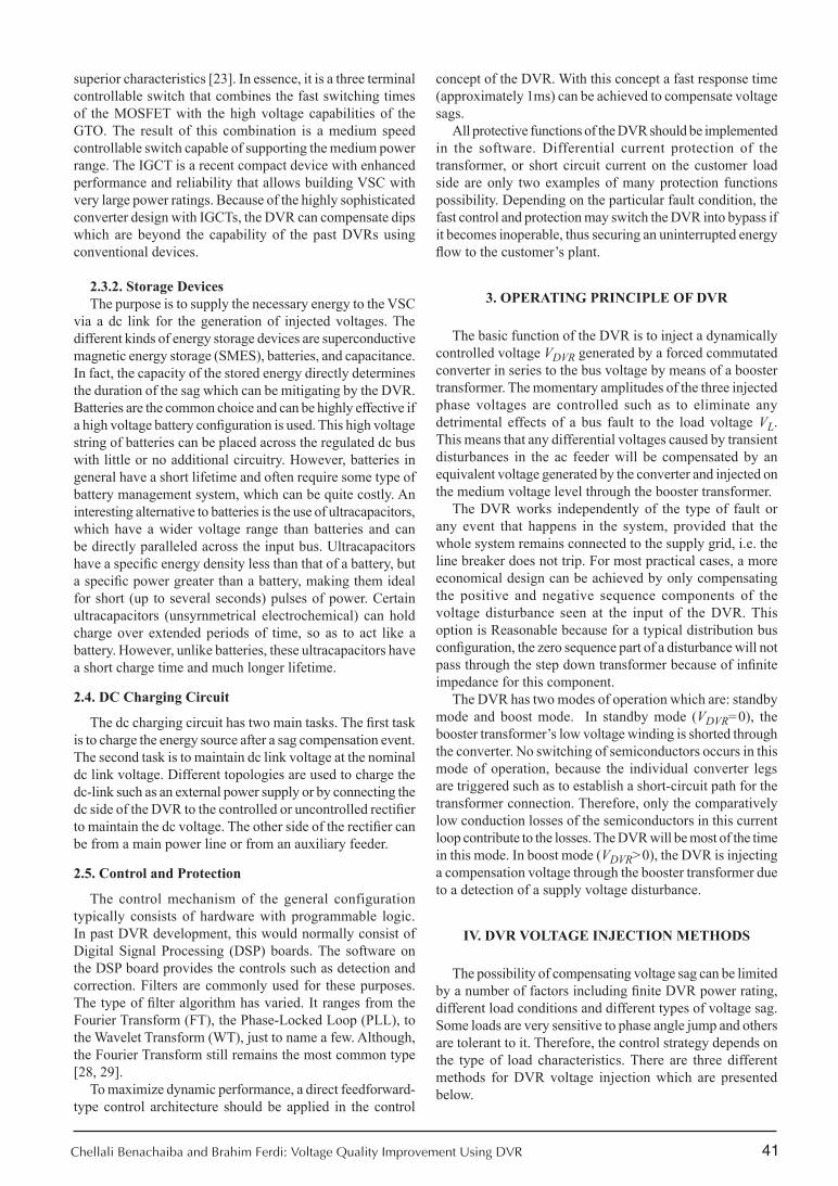
The PDC method tracks the supply voltage continuously and compensates load voltage during fault to pre-fault condition. In this method, the load voltage can be restored ideally, but the injected active power cannot be controlled and it is determined by external conditions such as the type of faults and load conditions. This method is achieved by using a fault detector to freeze the output from the Phase Locked Loop (PLL) circuit, when the fault occurs. Then, the frozen angle is used to restore the previous balanced load voltages by using the Park transform [10, 30, 31]. The lack of the negative sequence detection in this method leads to the phase-oscillation in the case of single-line faults. Figure 2 shows the single-phase vector diagram of this method.
According to Figure 2, the apparent power of DVR is:
( )1 1
2 2 2
DVR L DVR
L L S L S L S
S I V
I V V V V cos θ θ
=
= + − −
And the active power of DVR is:
( )1DVR L L L S SP I V cos V cosθ θ= −
The magnitude and the angle of DVR voltage are:
( )2 21 2DVR L S L S L SV V V V V cos θ θ= + − −
11
L L S SDVR
L L S S
V sin V sintan V cos V cosθ θ
θθ θ
− − = −
4.2. in-Phase compensation (iPc)
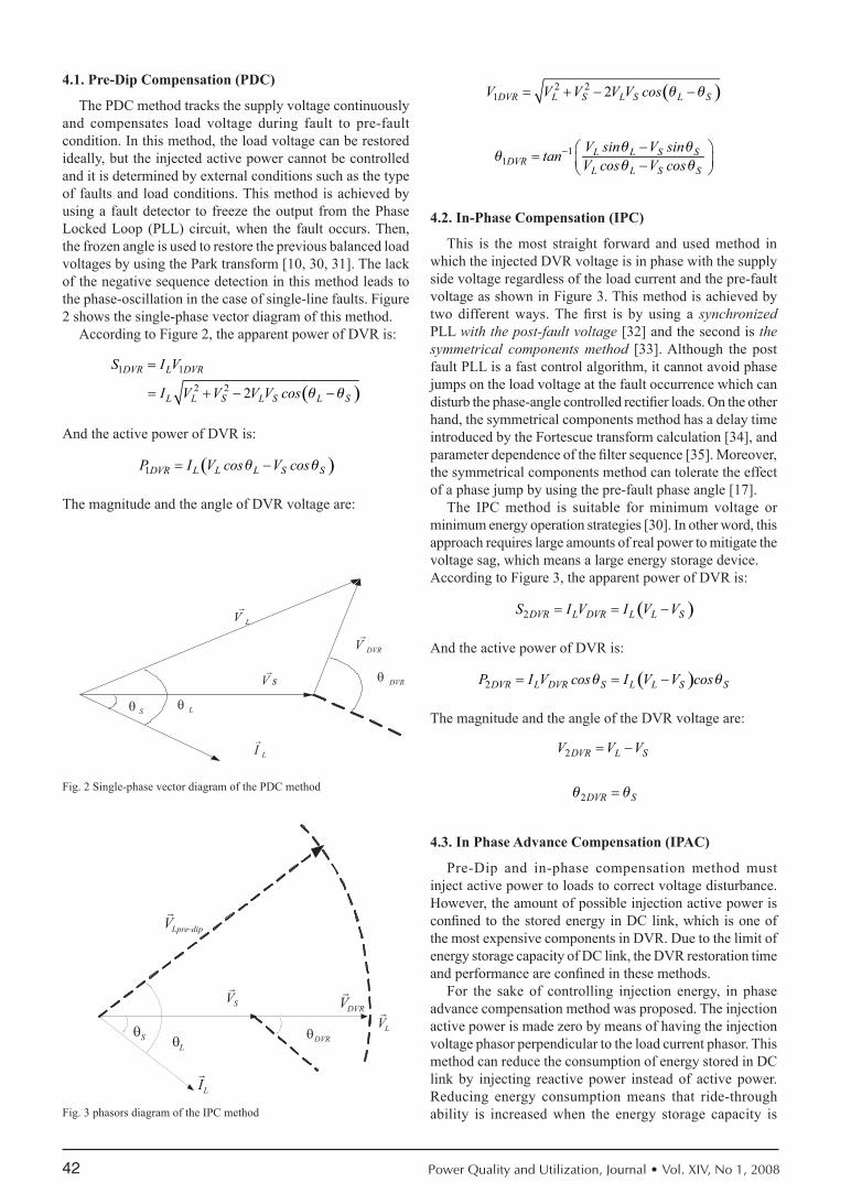
This is the most straight forward and used method in which the injected DVR voltage is in phase with the supply side voltage regardless of the load current and the pre-fault voltage as shown in Figure 3. This method is achieved by two different ways. The first is by using a synchronized PLL with the post-fault voltage [32] and the second is the symmetrical components method [33]. Although the post fault PLL is a fast control algorithm, it cannot avoid phase jumps on the load voltage at the fault occurrence which can disturb the phase-angle controlled rectifier loads. On the other hand, the symmetrical components method has a delay time introduced by the Fortescue transform calculation [34], and parameter dependence of the filter sequence [35]. Moreover, the symmetrical components method can tolerate the effect of a phase jump by using the pre-fault phase angle [17].
The IPC method is suitable for minimum voltage or minimum energy operation strategies [30]. In other word, this approach requires large amounts of real power to mitigate the voltage sag, which means a large energy storage device. According to Figure 3, the apparent power of DVR is:
( )2DVR L DVR L L SS I V I V V= = −
And the active power of DVR is:
( )2DVR L DVR S L L S SP I V cos I V V cosθ θ= = −
The magnitude and the angle of the DVR voltage are:
2
2
DVR L S
DVR S
V V V
θ θ
= −
=
4.3. in Phase advance compensation (iPac)
Pre-Dip and in-phase compensation method must inject active power to loads to correct voltage disturbance. However, the amount of possible injection active power is confined to the stored energy in DC link, which is one of the most expensive components in DVR. Due to the limit of energy storage capacity of DC link, the DVR restoration time and performance are confined in these methods.
For the sake of controlling injection energy, in phase advance compensation method was proposed. The injection active power is made zero by means of having the injection voltage phasor perpendicular to the load current phasor. This method can reduce the consumption of energy stored in DC link by injecting reactive power instead of active power. Reducing energy consumption means that ride-through ability is increased when the energy storage capacity is
Fig. 2 Single-phase vector diagram of the PDC method
Fig. 3 phasors diagram of the IPC method
43
fixed. On the other hand, the injection voltage magnitude of in-phase advance compensation method is larger than those of pre-dip or in-phase compensation methods and the voltage phase shift can cause voltage waveform discontinuity, inaccurate zero crossing and load power swing. Therefore, in phase advance compensation method should be adjusted to the load that is tolerant to phase angle jump, or transition period should be taken while phase angle is moved from pre-fault angle to advance angle.
In short, IPAC method uses only reactive power and unfortunately, not al1 the sags can be mitigated without real power, as a consequence, this method is only suitable for a limited range of sags.
5. simulaTioN
In order to show the performance of the DVR in voltage sags and swells mitigation, a simple distribution network is simulated using MATLAB (fig.1).Voltage sags and swells are simulated by temporary connection of different impedances at the supply side bus. A DVR is connected to the system through a series transformer with a capability to insert a maximum voltage of 50% of the phase to ground system voltage. Apart from this, a series filter is also used to remove any high frequency components of power. In this simulation the In-Phase Compensation (IPC) method is used. The load considered in the study is a 5.5 MVA capacity with 0.92p.f., lagging.
5.1. Voltage sags
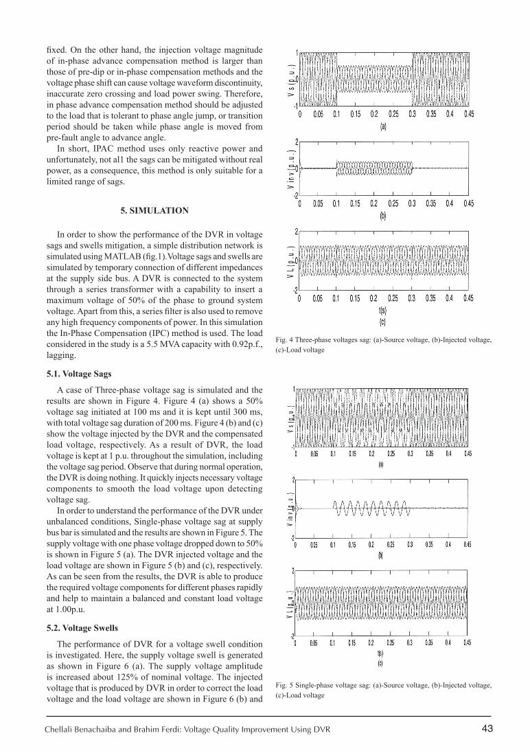
A case of Three-phase voltage sag is simulated and the results are shown in Figure 4. Figure 4 (a) shows a 50% voltage sag initiated at 100 ms and it is kept until 300 ms, with total voltage sag duration of 200 ms. Figure 4 (b) and (c) show the voltage injected by the DVR and the compensated load voltage, respectively. As a result of DVR, the load voltage is kept at 1 p.u. throughout the simulation, including the voltage sag period. Observe that during normal operation, the DVR is doing nothing. It quickly injects necessary voltage components to smooth the load voltage upon detecting voltage sag.
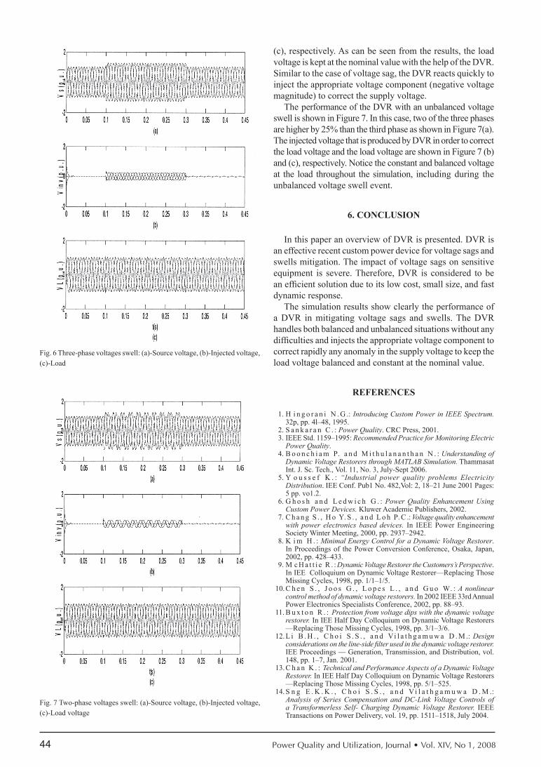
In order to understand the performance of the DVR under unbalanced conditions, Single-phase voltage sag at supply bus bar is simulated and the results are shown in Figure 5. The supply voltage with one phase voltage dropped down to 50% is shown in Figure 5 (a). The DVR injected voltage and the load voltage are shown in Figure 5 (b) and (c), respectively. As can be seen from the results, the DVR is able to produce the required voltage components for different phases rapidly and help to maintain a balanced and constant load voltage at 1.00p.u.
5.2. Voltage swells
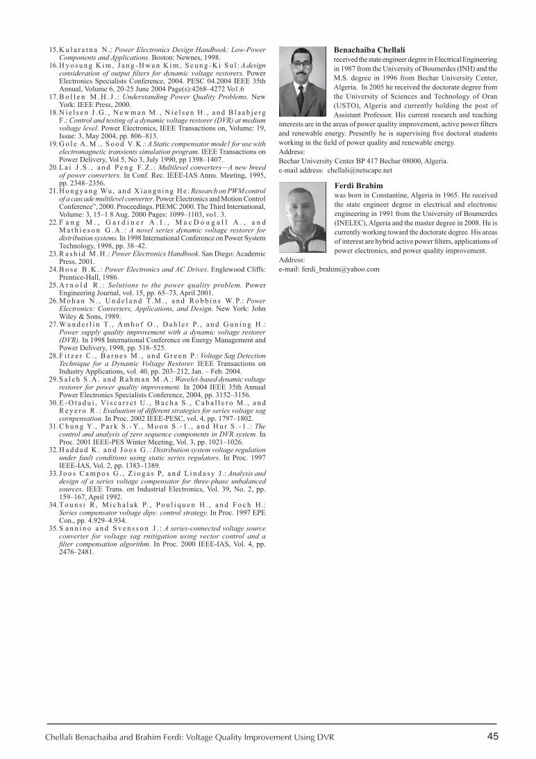
The performance of DVR for a voltage swell condition is investigated. Here, the supply voltage swell is generated as shown in Figure 6 (a). The supply voltage amplitude is increased about 125% of nominal voltage. The injected voltage that is produced by DVR in order to correct the load voltage and the load voltage are shown in Figure 6 (b) and
Fig. 4 Three-phase voltages sag: (a)-Source voltage, (b)-Injected voltage, (c)-Load voltage
Fig. 5 Single-phase voltage sag: (a)-Source voltage, (b)-Injected voltage, (c)-Load voltage
Chellali Benachaiba and Brahim Ferdi: Voltage Quality Improvement Using DVR
44 Power Quality and Utilization, Journal • Vol. XIV, No 1, 2008
(c), respectively. As can be seen from the results, the load voltage is kept at the nominal value with the help of the DVR. Similar to the case of voltage sag, the DVR reacts quickly to inject the appropriate voltage component (negative voltage magnitude) to correct the supply voltage.
The performance of the DVR with an unbalanced voltage swell is shown in Figure 7. In this case, two of the three phases are higher by 25% than the third phase as shown in Figure 7(a). The injected voltage that is produced by DVR in order to correct the load voltage and the load voltage are shown in Figure 7 (b) and (c), respectively. Notice the constant and balanced voltage at the load throughout the simulation, including during the unbalanced voltage swell event.
6. concLusion
In this paper an overview of DVR is presented. DVR is an effective recent custom power device for voltage sags and swells mitigation. The impact of voltage sags on sensitive equipment is severe. Therefore, DVR is considered to be an efficient solution due to its low cost, small size, and fast dynamic response.
The simulation results show clearly the performance of a DVR in mitigating voltage sags and swells. The DVR handles both balanced and unbalanced situations without any difficulties and injects the appropriate voltage component to correct rapidly any anomaly in the supply voltage to keep the load voltage balanced and constant at the nominal value.
reFerences
H i n g o r a n i N . G .: 1. Introducing Custom Power in IEEE Spectrum. 32p, pp. 4l–48, 1995.S a n k a r a n C . : 2. Power Quality. CRC Press, 2001.IEEE Std. 1159–1995: 3. Recommended Practice for Monitoring Electric Power Quality.B o o n c h i a m P. a n d M i t h u l a n a n t h a n N . : 4. Understanding of Dynamic Voltage Restorers through MATLAB Simulation. Thammasat Int. J. Sc. Tech., Vol. 11, No. 3, July-Sept 2006.Y o u s s e f K . : 5. “Industrial power quality problems Electricity Distribution. IEE Conf. Pub1 No. 482,Vol: 2, 18–21 June 2001 Pages: 5 pp. vo1.2.G h o s h a n d L e d w i c h G . : 6. Power Quality Enhancement Using Custom Power Devices. Kluwer Academic Publishers, 2002.C h a n g S . , H o Y. S . , a n d L o h P. C .: 7. Voltage quality enhancement with power electronics based devices. In IEEE Power Engineering Society Winter Meeting, 2000, pp. 2937–2942.K i m H . : 8. Minimal Energy Control for a Dynamic Voltage Restorer. In Proceedings of the Power Conversion Conference, Osaka, Japan, 2002, pp. 428–433.M c H a t t i e R . : 9. Dynamic Voltage Restorer the Customers’s Perspective. In IEE Colloquium on Dynamic Voltage Restorer—Replacing Those Missing Cycles, 1998, pp. 1/1–1/5.C h e n S . , J o o s G . , L o p e s L . , a n d G u o W. : 10. A nonlinear control method of dynamic voltage restorers. In 2002 IEEE 33rd Annual Power Electronics Specialists Conference, 2002, pp. 88–93.B u x t o n R . : 11. Protection from voltage dips with the dynamic voltage restorer. In IEE Half Day Colloquium on Dynamic Voltage Restorers —Replacing Those Missing Cycles, 1998, pp. 3/1–3/6.L i B . H . , C h o i S . S . , a n d Vi l a t h g a m u w a D . M .: 12. Design considerations on the line-side filter used in the dynamic voltage restorer. IEE Proceedings — Generation, Transmission, and Distribution, vol. 148, pp. 1–7, Jan. 2001.C h a n K . : 13. Technical and Performance Aspects of a Dynamic Voltage Restorer. In IEE Half Day Colloquium on Dynamic Voltage Restorers —Replacing Those Missing Cycles, 1998, pp. 5/1–525.S n g E . K . K . , C h o i S . S . , a n d Vi l a t h g a m u w a D . M .: 14. Analysis of Series Compensation and DC-Link Voltage Controls of a Transformerless Self- Charging Dynamic Voltage Restorer. IEEE Transactions on Power Delivery, vol. 19, pp. 1511–1518, July 2004.
Fig. 7 Two-phase voltages swell: (a)-Source voltage, (b)-Injected voltage, (c)-Load voltage
Fig. 6 Three-phase voltages swell: (a)-Source voltage, (b)-Injected voltage, (c)-Load
45
K u l a r a t n a N .: 15. Power Electronics Design Handbook: Low-Power Components and Applications. Boston: Newnes, 1998.H y o s u n g K i m , J a n g - H w a n K i m , S e u n g - K i S u l : 16. A design consideration of output filters for dynamic voltage restorers. Power Electronics Specialists Conference, 2004. PESC 04.2004 IEEE 35th Annual, Volume 6, 20-25 June 2004 Page(s):4268–4272 Vo1.6B o l l e n M . H . J . : 17. Understanding Power Quality Problems. New York: IEEE Press, 2000.N i e l s e n J . G . , N e w m a n M . , N i e l s e n H . , a n d B l a a b j e r g 18. F.: Control and testing of a dynamic voltage restorer (DVR) at medium voltage level. Power Electronics, IEEE Transactions on, Volume: 19, Issue: 3, May 2004, pp. 806–813.G o l e A . M . , S o o d V. K .: 19. A Static compensator mode1 for use with electromagnetic transients simulation program. IEEE Transactions on Power Delivery, Vol 5, No 3, July 1990, pp 1398–1407.L a i J . S . , a n d P e n g F. Z . : 20. Multilevel converters—A new breed of power converters. In Conf. Rec. IEEE-IAS Annu. Meeting, 1995, pp. 2348–2356.H o n g y a n g Wu , a n d X i a n g n i n g H e : 21. Research on PWM control of a cascade multilevel converter. Power Electronics and Motion Control Conference”, 2000. Proceedings. PIEMC 2000. The Third International, Volume: 3, 15–1 8 Aug. 2000 Pages: 1099–1103, vo1. 3.F a n g M . , G a r d i n e r A . I . , M a c D o u g a l l A . , a n d 22. M a t h i e s o n G . A . : A novel series dynamic voltage restorer for distribution systems. In 1998 International Conference on Power System Technology, 1998, pp. 38–42.R a s h i d M . H .: 23. Power Electronics Handbook. San Diego: Academic Press, 2001.B o s e B . K . : 24. Power Electronics and AC Drives. Englewood Cliffs: Prentice-Hall, 1986.A r n o l d R . : 25. Solutions to the power quality problem. Power Engineering Journal, vol. 15, pp. 65–73, April 2001.M o h a n N . , U n d e l a n d T. M . , a n d R o b b i n s W. P.:26. Power Electronics: Converters, Applications, and Design. New York: John Wiley & Sons, 1989.W u n d e r l i n T. , A m h o f O . , D a h l e r P. , a n d G u n i n g H .: 27. Power supply quality improvement with a dynamic voltage restorer (DVR). In 1998 International Conference on Energy Management and Power Delivery, 1998, pp. 518–525.F i t z e r C . , B a r n e s M . , a n d G r e e n P.: 28. Voltage Sag Detection Technique for a Dynamic Voltage Restorer. IEEE Transactions on Industry Applications, vol. 40, pp. 203–212, Jan. – Feb. 2004.S a l e h S . A . a n d R a h m a n M . A .: 29. Wavelet-based dynamic voltage restorer for power quality improvement. In 2004 IEEE 35th Annual Power Electronics Specialists Conference, 2004, pp. 3152–3156.E - O t a d u i , Vi s c a r r e t U . , B a c h a S . , C a b a l l e r o M . , a n d 30. R e y e r o R . : Evaluation of different strategies for series voltage sag cornpensation. In Proc. 2002 IEEE-PESC, vol. 4, pp. 1797–1802.C h u n g Y. , P a r k S . - Y. , M o o n S . - 1 . , a n d H u r S . - 1 . : 31. The control and analysis of zero sequence components in DVR system. In Proc. 2001 IEEE-PES Winter Meeting, Vol. 3, pp. 1021–1026.H a d d a d K . a n d J o o s G . : 32. Distribution system voltage regulation under fault conditions using static series regulators. In Proc. 1997 IEEE-IAS, Vol. 2, pp. 1383–1389.J o o s C a m p o s G . , Z i o g a s P, a n d L i n d a s y J .: 33. Analysis and design of a series voltage compensator for three-phase unbalanced sources. IEEE Trans. on Industrial Electronics, Vol. 39, No. 2, pp. 159–167, April 1992.T o u n s i R , M i c h a l a k P. , P o u l i q u e n H . , a n d F o c h H .: 34. Series compensator voltage dips: control strategy. In Proc. 1997 EPE Con., pp. 4.929–4.934.S a n n i n o a n d S v e n s s o n J . : 35. A series-connected voltage source converter for voltage sag rnitigation using vector control and a filter compensation algorithm. In Proc. 2000 IEEE-IAS, Vol. 4, pp. 2476–2481.
Chellali Benachaiba and Brahim Ferdi: Voltage Quality Improvement Using DVR
Benachaiba chellali received the state engineer degree in Electrical Engineering in 1987 from the University of Boumerdes (INH) and the M.S. degree in 1996 from Bechar University Center, Algeria. In 2005 he received the doctorate degree from the University of Sciences and Technology of Oran (USTO), Algeria and currently holding the post of Assistant Professor. His current research and teaching
interests are in the areas of power quality improvement, active power filters and renewable energy. Presently he is supervising five doctoral students working in the field of power quality and renewable energy. Address: Bechar University Center BP 417 Bechar 08000, Algeria.e-mail address: [email protected]
Ferdi Brahim was born in Constantine, Algeria in 1965. He received the state engineer degree in electrical and electronic engineering in 1991 from the University of Boumerdes (INELEC), Algeria and the master degree in 2008. He is currently working toward the doctorate degree. His areas of interest are hybrid active power filters, applications of power electronics, and power quality improvement.
Address:e-mail: [email protected]

46 Power Quality and Utilization, Journal • Vol. XIV, No 1, 2008


![Electrical Power Quality and Utilisation, Journal Vol. …2].pdf47 Electrical Power Quality and Utilisation, Journal Vol. XV, No. 2, 2009 Estimation of Optimum Value of Y-Capacitor](https://img.pdfslide.us/doc/110x75/5ae959477f8b9aee0790b35d/electrical-power-quality-and-utilisation-journal-vol-2pdf47-electrical-power.jpg)


![Electrical Power Quality and Utilisation, Journal Vol. …2].pdf7 Electrical Power Quality and Utilisation, Journal Vol. XV, No. 2, 2009 Power Quality and EMC in Smart Grid Magnus](https://img.pdfslide.us/doc/110x75/5ae959477f8b9aee0790b36c/electrical-power-quality-and-utilisation-journal-vol-2pdf7-electrical-power.jpg)