Embed Size (px)
Citation preview

ELECTRICAL
MACHINES

Design & Project & Production & Trading of Industrial and Educational Instruments and Equipment
SAMAR s.r.l. Web: www.samar-instruments.it Via della Pace n. 25 Fr. Zivido - 20098 San Giuliano Milanese - Milano – Italy Tel.: (++39) 02 98242255 (r.a.) Fax:(++39) 02 98242279 E-mail: [email protected]
Catalogue on line: www.samarinternet.com
Rev 04.15
BASIC ELECTRICAL MACHINES
TRAINING SYSTEM
ELECTRICAL MACHINES TECHNOLOGY MODULE
The common objective guiding the design of this equipment is the development of tools that are the core of training programs about the latest
manufacturing and service technologies and techniques.
In following these programs the students acquire theoretical knowledge and practical experience on machines that are basically of an industrial
type, but so arranged as to provide maximum learning profitability to them.
Also great attention has been given to the human interface to provide a system that is safe, user friendly, easy to understand, continuously
updated and tuned to the actual industrial, real life world.
Some of the design features that provide our equipment with an outstanding training value are described below.
CONSTRUCTION
The ELECTRICAL MACHINES TRAINER provides a complete range of integrated teaching equipment for the various subjects of both AC and
DC machines. All equipment is implemented in rugged enclosures. The modules can be optionally mounted on an alluminium frame, when being
exercised or when stored, and can be used both for individual or for group demonstration purposes. The machines within the same power range
are fully compatible among them, both mechanically and electrically. They can be easily and quickly assembled on a test board that ensures safe
coupling and noiseless, smooth and vibration free running. Educational boards with 4 mm safety terminals and printed electrical diagrams are
mounted on each machine.
Half-coupling joints are provided with shock absorbers and rotating parts are covered with protection guards.
Different types of brakes and dynamometers are available for controlling and measuring the loads of the motors under test.
Torque measuring is bi-directional by means of a mechanical levelling system or a thin film strain gauge load cell. Speed and torque readings are
normally digital. However, analog, or analog-digital instruments are available on request.
A computerized electrical machine test system is available to read and process the parameters of machines under test. By entering data
manually the tests can be simulated. Brakes are sized for a breaking power greater than the overload power of the motors.
Power range of the machines, and therefore power requirements, can vary from the S series (fractional Horse Power), to the M series
(approximately 1 KW) and the L series (up to 5 Kw). For the operation of a typical experimental group, a bench with a working area of 2000 x
700 mm is required.

Design & Project & Production & Trading of Industrial and Educational Instruments and Equipment
SAMAR s.r.l. Web: www.samar-instruments.it Via della Pace n. 25 Fr. Zivido - 20098 San Giuliano Milanese - Milano – Italy Tel.: (++39) 02 98242255 (r.a.) Fax:(++39) 02 98242279 E-mail: [email protected]
Catalogue on line: www.samarinternet.com
Rev 04.15
EXPERIMENTAL GROUPS
Several different experimental groups can be selected by the user, each group using the same power supply, loads and control/accessory
modules. The attached selection matrix may be used to identify the essential and the recommended items required to provide complete
experimental components for each type of machine.
Each electrical machine test bench is normally intended for 3 to 4 students groups, but can be easily handled by two. The system requires a
three-phase supply, 5 wire, 220/380 V, 50 Hz (or according to local voltages).
SAFETY
Our power supply is provided with built-in differential, earth leakage and magneto-thermal protections that ensure a safe operation and
protection of the equipment against damages caused by incorrect use. An over-speed protection is available on request.
Electrical connections are performed via 4 mm safety cables and terminals. Use of our set of cables is recommended
FLEXIBILITY AND COMPATIBILITY The instruments provided are electrically compatible with the various machines of the range. Load modules can be connected in
series, parallel, delta and star with no limitation, and are suitable for testing generators and transformers even in overload conditions
TEACHING LEVEL
The flexible and modular design enables to select a wide range of electrical machines test methods, varying in complexity from simple motor
load test up to fully automated PC based measurement and control system.
Therefore the teaching level can vary from the technician level up to graduate level and researcher.
EXPANSIONS AND INTERFACING
The electrical machines test systems can be integrated with our power electronic drivers for open or closed loop speed control of DC motors and
variable speed control of AC motors. Included are computer interfaces for real time monitoring and control techniques under varying load
conditions
ORIGIN
Our electrical machines and accessories are manufactured in Italy.
COURSEWARE
An experiment manual is provided which contains, for each experiment, a theoretical review, circuit diagrams, experiment
execution procedure in a step by step approach and worksheets for tabling and graphing the experiment results. Some of the
typical experiments covered are listed below (others can be designed by the user as necessary).
SINGLE AND THREE PHASE TRANSFORMERS
MEASUREMENT OF WINDING RESISTANCE
MEASUREMENT OF TRANSFORMATION RATIO
NO LOAD TEST
SHORT CIRCUIT TEST
AC ASYNCHRONOUS MACHINES
MEASUREMENT OF WINDING RESISTANCE
MEASUREMENT OF SLIP RING MOTOR TRANSFORMATION RATIO
NO LOAD TEST
SHORT CIRCUIT TEST
DETERMINATION OF WORKING CHARACTERISTICS
AC SYNCHRONOUS MACHINES
MEASUREMENT OF WINDING RESISTANCE
NO LOAD TEST
SHORT CIRCUIT TEST
DETERMINATION OF WORKING CHARACTERISTICS
DC MACHINES
MEASUREMENT OF WINDING RESISTANCE
MAGNETIC CHARACTERISTIC
NO LOAD TEST
DETERMINATION OF WORKING CHARACTERISTICS

Design & Project & Production & Trading of Industrial and Educational Instruments and Equipment
SAMAR s.r.l. Web: www.samar-instruments.it Via della Pace n. 25 Fr. Zivido - 20098 San Giuliano Milanese - Milano – Italy Tel.: (++39) 02 98242255 (r.a.) Fax:(++39) 02 98242279 E-mail: [email protected]
Catalogue on line: www.samarinternet.com
Rev 04.15
COMPUTER BASED SYSTEM
In alternative to the manual test system, the above experiments can be executed with a computer based system. In this case the electrical
machines are connected to a data acquisition box that communicates with a personal computer. The parameters of the tests are read directly
into the computer where they are processed for presentation in tables and graphs.
The experiments can also be simulated by entering data manually through the PC keyboard. Four software programs are available for testing
Transformers, AC Asynchronous Machines, AC Synchronous Machines and DC Machines respectively
ADVANTAGES The following are the distinct advantages of the SAMAR test systems:
Any machine can be coupled with any other. Due to the unique SAMAR motor fastening system, the position of the machine shaft on the three
axes (X, Y and Z) can be easily and precisely adjusted. By means of a simple kit of accessories it is possible to mechanically couple any machines
of the same power range, expand the laboratory possibilities and rationalise the set of equipment to avoid any unwanted duplication.
All units are designed to perfectly integrate each other. For example, the power supply is suitable for the educational machines, for the motor
and transformer kits and for the motor assembling system; the electrical machines are fully compatible with the power electronics trainer of the
electronics section
SYSTEM SELECTION
To better clarify the use of the Components Selection Table shown below, we propose an example of how a complete list of the required
equipment can be produced.
1. Course content
First of all the course subjects must be defined: in or example it is assumed that the course will cover three and single phase transformers, three
phase motors and generators, single phase motors, DC motors and generators.
2. Number of students and stations
Then, the number of students: the laboratory of our example will include 24 students, 3 per test station, therefore 8 stations will be required.
3. Parallel work or rotation
A compromise must be reached between simultaneous operation on 8 identical stations (which can simplify the laboratory supervision but
requires equipment duplication), and student rotation (which reduces the equipment need but requires careful planning). It is decided to
provide the following 8 test stations and one instrument bench
TEST STATIONS
Test stations N° 1 and 2 - Single and 3phase transformers
Composed by 2 sets of : Single phase transformer; Three phase transformer; Power supply; Resistive Load; Power measuring
module; Set of cables; Working bench; Panel support and 1 set of: Capacitive load, Inductive load
Test stations N° 3 and 4 - Single and three phase motors
Composed by 2 sets of: Squirrel cage motor; Power supply; Coupling base; Eddy current brake; Tachometer; Power measuring
module; Set of cables; Working bench; Panel support and 1 set of: Synchronous machine, 2 speed motor, Capacitor motor,
Starting rheostat, Excitation rheostat, Load cell, Star-delta starter, Two speed starter, Speed control trainer
Test stations N° 5 and 6 - Three phase generators
Composed by 2 sets of : Synchronous machine; Power supply; Coupling base; DC driving motor; Resistive load; Tachometer, Power
measuring module; Set of cables; Working bench; Panel support and 1 set of: Starting rheostat, Excitation rheostat, Inductive load,
Capacitive load, Paralleling board
Test stations N° 7 and 8 - DC motors and generators
Composed by 2 sets of : DC machine compound excitation; DC machine series excitation; Power supply; Coupling base; DC
machine shunt excitation in brake version; Resistive load; Tachometer; Working bench; Set of cables; Panel support and 1 set of:
Torque measuring by load cell, Starting rheostat, Excitation rheostat, Speed control trainer, Power electronics trainer
Instrument Bench - Automatic test system
Composed by one set of : Measuring instruments with serial interface USB, PC and related Software, Working bench
Note: Machines and other accessories for this test bench are obtained from the above 8 stations.

Design & Project & Production & Trading of Industrial and Educational Instruments and Equipment
SAMAR s.r.l. Web: www.samar-instruments.it Via della Pace n. 25 Fr. Zivido - 20098 San Giuliano Milanese - Milano – Italy Tel.: (++39) 02 98242255 (r.a.) Fax:(++39) 02 98242279 E-mail: [email protected]
Catalogue on line: www.samarinternet.com
Rev 04.15
ELECTRICAL MACHINES TECHNOLOGY
COMPONENTS SELECTION TABLE
Description Code Essential/
Recomm. Purpose
Q.ty (for 24
Students)
min/max POWER SUPPLIES
Universal Power Supply A0240 E/R
Provides variable AC and DC supplies for powering AC and
DC machines; extensive protections are included against
misuse - programmable version available
6/8
TRANSFORMERS
Single Phase A4110 E/R For Lab experiences and single phase voltage step-up/down 6/8
Three Phase A4120 E/R For Lab experiences and three phase voltage step-up/down 6/8
THREE PHASE MOTORS
Squirrel Cage Motor A4220 E/R For Lab experiences and as a driver for AC and DC
generators and for studying different starting methods 6/8
Slip Ring Motor A4222 E/R
For Lab experiences, as a driver for AC and DC generators
and as voltage phase shifter for studying rotating magnetic
fields
6/8
Synchronous Machine A4223 E/R For Lab experiences, as AC generator and synchronous
motor 6/8
Two Speed Motor A4224 E/R For Lab experiences , as a driver and for studying motor
speed controls 6/8
THREE PHASE GENERATORS
Synchronous Machine A4223 E/R For Lab experiences, as AC generator and synchronous
motor 3/4 (*)
SINGLE PHASE MOTORS
Capacitor Run Motor A4230 E/R
For Lab experiences, as a driver motor and for studying
single phase motors starting methods and ways of
producing rotating magnetic fields
4/6
Capacitor Start Motor A4232 E/R
For Lab experiences, as a driver motor and for studying
single phase motors starting methods and ways of
producing rotating magnetic fields
4/6
Universal Motor A4234 E/R For Lab experiences, as a driver motor, repulsion motor and
for studying effects of magnetic fields 4/6
DC MACHINES
Compound Excitation A4240 E/R For Lab experiences, as driver DC motor and DC generator 4/6
Series Excitation A4242 E/R For Lab experiences and DC driver motor 4/6
Shunt Excitation A4244 E/R For Lab experiences, as driver DC motor and DC generator 4/6
ASSEMBLING KITS
Motor Assembling Kit A3110 E/R
For studying motor construction details to integrate the
theory; the motor can subsequently be used for any Lab
requirement
3/4
Transformer
Assembling kit A3120 E/R
For studying transformer construction details to integrate
the theory; the transformer can subsequently be used for
any Lab requirement
3/4
UNIVERSAL MACHINE
Universal Machine A4300 E/R
Flexible and comprehensive system for a great variety of
Lab requirements: most rotating electrical machines can be
assembled and coupled by means of a set of modular
components (stators, rotors, coupling accessories and base)
2/4
COUPLING BASE
Coupling Base A4840 E/R
For coupling two machines on a base by fastening and
aligning them with a quick method that does not require
tools
6/8
BRAKES
Eddy Current Brake A4420 E/R Provides a load for testing motors 1/2
Braking DC Generator A4430 E/R Provides a means for loading motors and measuring torque 6/8
LOADS
Resistive Load A4510 E/R Resistive load for testing AC and DC generators 6/8
Capacitive Load A4520 E/R Capacitive load for testing AC generators 4/6
Inductive Load A4530 E/R Inductive load for testing AC generators 4/6
Resistive Capacitive Inductive Load RLC E/R Resistive Capacitive Inductive Load for testing AC
generators - programmable version available 6/8
RHEOSTATS
Starter for DC Motors A4610 E/R Rheostat for starting DC motors 6/8
Starter for AC Motors A4620 E/R Rheostat for starting 3 phase AC motors 6/8
Excitation Rheostat A4630 E/R Rheostat for controlling excitation in DC and synchronous
AC machines 6/8

Design & Project & Production & Trading of Industrial and Educational Instruments and Equipment
SAMAR s.r.l. Web: www.samar-instruments.it Via della Pace n. 25 Fr. Zivido - 20098 San Giuliano Milanese - Milano – Italy Tel.: (++39) 02 98242255 (r.a.) Fax:(++39) 02 98242279 E-mail: [email protected]
Catalogue on line: www.samarinternet.com
Rev 04.15
Description Code Essential/
Recomm. Purpose
Q.ty (for 24
Students)
min/max METERS
Tachometer optical version SM/RPM E/R Digital RPM meter optical version 6/8
Torque Meter A4730 E/R For measuring torque with the braking DC generator A4430 6/8
Transducer for A4730 A4731 E/R Sensor that provides input to the torque meter 6/8
Electrical Power Measuring Module A4750 E/R For measuring all DC and AC parameters in the electrical
Lab 6/8
Computer Base System ETC R
A Personal Computer reads the electrical test data through
a data acquisition box and presents processed results to
the operator; suitable also for simulating tests without
connecting the machines
1
ACCESSORIES
Paralleling Board A4810 R For connecting in parallel two or more AC generators or
generators and power line 1/2
STAR-DELTA Starter A4820 E/R For starting AC motor in a STAR configuration and then
switching to DELTA 1/2
Two Speed Commutator A4830 E/R To start the 4-2 poles motor A4224 on 4 poles and then
switching to 2 poles for double speed 1/2
Cable Set A4890 E/R For connecting all machines and instruments; 4 mm safety
terminals and coloured leads ensure a safe use 6/8
DRIVERS
Power Electronics Trainer B3600 E/R For study of the power electronics used to drive electric
motors 1/2
Speed Control for DC Motors REG/CC E/R For experiences on controlling DC motor speed 2/4
Speed Control for AC motors REG/CA E/R For experiences on controlling AC motor speed 2/4
NOTES
Code: Model Code - For power range consult the SAMAR Catalogue; power of machines, accessories and loads should
be matched
E/R: Essential/Recommended component. Essential components are required to perform the basic experiments. Recommended
components provide additional and higher level training capabilities
Q.ty: Essential/Recommended quantities for an effective and comprehensive training system. The quantities are for a 24 students
laboratory.

Design & Project & Production & Trading of Industrial and Educational Instruments and Equipment
SAMAR s.r.l. Web: www.samar-instruments.it Via della Pace n. 25 Fr. Zivido - 20098 San Giuliano Milanese - Milano – Italy Tel.: (++39) 02 98242255 (r.a.) Fax:(++39) 02 98242279 E-mail: [email protected]
Catalogue on line: www.samarinternet.com
Rev 04.15
ELECTRICAL MACHINES
TRAINER REMOVABLE ELECTRICAL MACHINE SYSTEM TYPE A43.00 This Trainer consists of a set of modular components that can be assembled in different configurations to construct most rotating machines such as:
− 2 and 4 poles AC squirrel cage motor
− 2 poles AC slip ring motor
− Single phase AC capacitor motor
− Single phase AC repulsion motor
− AC synchronous motor
− AC synchronous generator
− AC/DC universal motor
− DC series excitation machine
− DC shunt excitation machine
− DC compound excitation machine
− DC independent excitation machine
The components are:
− One AC stator
− One DC stator
− One squirrel cage rotor
− One slip ring rotor and brush set
− One collector rotor and brush set
− One starting capacitor
− Coupling base
− Safety guard
The stators are permanently mounted on a coupling base on which four supports hold the rotors and brush sets. The supports are fastened by means of knobs
that can be easily removed without the need of any tool, to exchange the rotors and brushes and implement the desired configuration. A compact and
integrated laboratory is made available to perform most experiments and tests on standard electrical machines. The advantages are obviously its lower cost
compared to that of a set of discrete machines, their modularity and, owing to the complete visibility of the components, the possibility for the student to learn
the electrical and mechanical details. The windings are connected to terminal boards on top of which they are clearly identified by drawings that show the
internal logic and make their understanding and connections easy in the different possible combinations. The synchronous machine is in all respect a real
implementation and not a simulated function of the asynchronous unit. A brake generator can be easily connected coaxial to the trainer for performing load
tests. A manual supplied with the unit describes in detail the electrical connections and the mechanical assembling procedure
TECHNICAL DATA
OPTIONAL UNITS
A4S Electrical Machines Training System (*)
A0240 Power supply
A4430 Brake Generator
A4725 Digital RPM Hand Meter
A4630 Excitation Rheostat
A4810 Paralleling Board
A4890 Set of cables
A4891 Cables support
The unit allows the students to perform a
range of experiments such as:
Disassembling and assembling
No-load tests
Short circuit tests
Nominal load and overload tests
External characteristics
Excitation characteristics
Determination of efficiency
Speed control
Different starting methods
AC and DC generation
Paralleling of AC generators
Power factor control
(*) 60 Hz version available on request
(**) When AC generator
Input Voltage
Output
Voltage
Approx.
RPM
Excitation
Voltage
Approx.
Power
AC Unit
220 to 240 V
380 to 415 V
3 /1 phase 50
Hz (*)
- 1,500/3,000 - 300 W
DC Unit 220 V DC 220 V DC
220 VAC (**) 3,000 220 VDC 300 W
ORDERING CODES
A4300 - 50 Hz Trainer
A4300A - 60 Hz Trainer
Load Modules (**)
Measuring Modules (**)
Work Table (**)
Trolley (**)
(*) It includes a suggested set of machines, instruments and accessories
required to set-up an electrical machines laboratory
(**) See SAMAR general Catalogue

Design & Project & Production & Trading of Industrial and Educational Instruments and Equipment
SAMAR s.r.l. Web: www.samar-instruments.it Via della Pace n. 25 Fr. Zivido - 20098 San Giuliano Milanese - Milano – Italy Tel.: (++39) 02 98242255 (r.a.) Fax:(++39) 02 98242279 E-mail: [email protected]
Catalogue on line: www.samarinternet.com
Rev 04.15
A4220 - SQUIRREL CAGE THREE PHASE MOTORS This is a series of educational motors that are basically industrial models especially equipped to be suitable for training. For this purpose the windings ends are
connected to 4 mm safety sockets in a metal housing on top of which a clear electrical drawing shows the internal logic. The students can therefore easily
understand operation and windings connections that can be configured for STAR or DELTA schemes. The units can be supplied with an experiment manual which
explains typical exercises that can be executed on these machines. A comprehensive set of accessories and a joint allow easy and quick coupling with other
machines or with a brake.
OPTIONAL ACCESSORIES A42CO Coupling accessories, composed of a half coupling joint and all required hardware to fasten the motor to the
coupling base (or to the Universal coupling base, to be specified when ordering) . They are required when the motor is to be coupled to a brake or other machines.
A42DS Double shaft
A42FS Fault simulator. The ends of the stator windings are connected to a series of switches hidden inside a box installed between the motor casting and the
terminal board. Through the switches the windings are then connected to the standard connectors on the board. The instructor activates the switches to simulate
faults and assigns to the student the task of analyzing and explaining them.
The following faults can be simulated: Open windings - Shorts between windings - Poor insulation of windings
The motor is supplied with a manual explaining the feasible faults and the corresponding switch settings
OPTIONAL UNITS Power supply
Brake Generator
Star-Delta starter
Coupling base
Flywheel
Set of cables
Cables support
Measuring modules
PC Interface accessories
Working table or Trolley
A4220C – SQUIRREL CAGE CUTAWAY VERSION The windings and the mechanical parts are perfectly visible so allowing the student
to have a good knowledge of the manufacturing techniques.
They are mounted on a base 28 x 32 cm approx. The dimensions of the machines are
suitable to see the internal construction.
TECHNICAL AND ORDERING INFORMATION
Model N. Input Voltage
Volts (∆/Y)
Freq.
Hz
Nominal Speed
Approx. RPM*
Nominal Power
Approx. KW
A4220S 220/380** 50 3.000 0,2***
A4220AS 127/220 60 3.600 0,2***
A4220M 220/380** 50 3.000 1,1
A4220AM 127/220 60 3.600 1,1
A4220L 220/380** 50 3.000 3,0
A4220AL 127/220 60 3.600 3,0
Industrial version is available. Add I to Model Number
Kit versions are available. Add K to Model Number
Cutaway models are available. Add C to Model Number
* Four Poles Motors are available. Add 4 to Model N. (Ex. A4220AS/4)
** 230/400V and 240/415V are available. Specify on order
*** 0,1 - 0,3 and 0,5 KW are available and can be quoted on request.
NOTE: Powers are indicative and reflect the ranges of the industry
standards.
TYPICAL EXPERIMENTS
Measurement of winding
resistance
Short circuit test
No-Load test
Efficiency determination
External characteristics
STAR-DELTA starting

Design & Project & Production & Trading of Industrial and Educational Instruments and Equipment
SAMAR s.r.l. Web: www.samar-instruments.it Via della Pace n. 25 Fr. Zivido - 20098 San Giuliano Milanese - Milano – Italy Tel.: (++39) 02 98242255 (r.a.) Fax:(++39) 02 98242279 E-mail: [email protected]
Catalogue on line: www.samarinternet.com
Rev 04.15
A4222 - SLIP RING THREE PHASE MOTORS This is a series of educational motors that are basically industrial models especially equipped to be suitable for training. For this purpose the windings ends are
connected to 4 mm safety sockets in a metal housing on top of which a clear electrical drawing shows the internal logic. The students can therefore easily
understand operation and windings connections. The stator can be configured for STAR or DELTA schemes. The motor can work as a squirrel cage if the rotor
brushes are short-circuited. The units can be supplied with an experiment manual, which explains typical exercises that can be executed on these machines. A
comprehensive set of accessories and a joint allow easy and quick
OPTIONAL ACCESSORIES A42CO Coupling accessories, composed of a half coupling joint and all required hardware to fasten the motor to the coupling base (or to the Universal
coupling base, to be specified when ordering). They are required when the motor is to be coupled to a brake or other machines A42DS Double shaft OPTIONAL UNITS Power supply Brake Generator Rotoric Starter Coupling base Flywheel Set of cables Cables support Measuring modules PC Interface accessories Working table or Trolley
A4222C – SLIP RING CUTAWAY VERSION
The windings and the mechanical parts are perfectly visible so allowing
the student to have a good knowledge of the manufacturing techniques.
They are mounted on a base 28 x 32 cm approx. The dimensions of the
machines are suitable to see the internal construction
TECHNICAL AND ORDERING INFORMATION
Model N. Input Voltage
Volts (∆/Y)
Freq.
Hz
Nominal Speed
Approx. RPM*
Nominal Power
Approx. KW
A4222S 220/380** 50 3.000 0,2***
A4222AS 127/220 60 3.600 0,2***
A4222M 220/380** 50 3.000 1,1
A4222AM 127/220 60 3.600 1,1
A4222L 220/380** 50 3.000 3,0
A4222AL 127/220 60 3.600 3,0
Industrial version is available. Add I to Model Number
Kit version is available. Add K to Model Number
Cutaway models are available. Add C to Model Number
* Four Poles Motors are available. Add 4 to Model N. (Ex. A42.22AS/4)
** 230/400V and 240/415V are available. Specify on order
*** 0,1 - 0,3 and 0,5 KW are available and can be quoted on request
NOTE: Powers are indicative and reflect the ranges of the industry
standards
TYPICAL EXPERIMENTS
Measurement of Winding Resistance
Short circuit test
No-Load Test
Efficiency determination
External Characteristics

Design & Project & Production & Trading of Industrial and Educational Instruments and Equipment
SAMAR s.r.l. Web: www.samar-instruments.it Via della Pace n. 25 Fr. Zivido - 20098 San Giuliano Milanese - Milano – Italy Tel.: (++39) 02 98242255 (r.a.) Fax:(++39) 02 98242279 E-mail: [email protected]
Catalogue on line: www.samarinternet.com
Rev 04.15
A4223 - SYNCHRONOUS THREE PHASE MACHINES This is a series of educational motors/generators that are basically industrial models especially equipped to be suitable for training. For this purpose the windings
ends are connected to 4 mm safety sockets in a metal housing on top of which a clear electrical drawing shows the internal logic. The students can therefore easily
understand operation and windings connections. The stator can be configured for STAR or DELTA schemes. The units can be supplied with an experiment manual
which explains typical exercises that can be executed on these machines. A comprehensive set of accessories and a joint allow easy and quick
OPTIONAL ACCESSORIES A42CO Coupling accessories, composed of a half coupling joint and all required hardware to fasten the motor to the coupling base
(or to the Universal coupling base, to be specified when ordering) . They are required when the motor is to be coupled to a brake
or other machines.
A42DS Double shaft
OPTIONAL UNITS
Power supply
Driving motor
Brake Generator
R-C-L Loads
Excitation Rheostat
Paralleling Board
Coupling base
Flywheel
Set of cables
Cables support
Measuring modules
PC Interface accessories
Working table or Trolley
A4223C – SYNCHRONOUS MACHINE CUTAWAY VERSION
The windings and the mechanical parts are perfectly visible so allowing the
student to have a good knowledge of the manufacturing techniques.
They are mounted on a base 28 x 32 cm approx. The dimensions of the
machines are suitable to see the internal construction
TECHNICAL AND ORDERING INFORMATION
Model N.
Motor Input Voltage
Generator Output Voltage
Volts ∆/Y
Freq.
Hz
Nominal Speed
RPM
Nominal Power
Approx. KW
A4223S 220/380** 50 3.000 0,2***
A4223AS 127/220 60 3.600 0,2***
A4223M 220/380** 50 3.000 1,0
A4223AM 127/220 60 3.600 1,0
A4223L 220/380** 50 3.000 2,4
A4223AL 127/220 60 3.600 2,4
Industrial version is available. Add I to Model Number
Kit version is available. Add K to Model Number
Cutaway models are available. Add C to Model Number
* Four Poles Motors are available. Add 4 to Model N. (Ex. A42.23AS/4)
** 230/400V and 240/415V are available. Specify on order
*** 0,1 - 0,3 - 0,5 and 3 KW are available and can be quoted on request
NOTE: Powers are indicative and reflect the ranges of the industry standards
TYPICAL EXPERIMENTS
Measurement of winding resistance
Short circuit Test
No-load test
Efficiency determination
External characteristics
OPTION: A4223-REG – ALTERNATOR VOLTAGE CONTROLLER
The A4223 controller is designed to provide output voltage control and stabilization in AC generation
sets. Its function is to monitor the alternator output voltage and provide a feedback signal in the form
of a DC voltage suitable to drive the field inductor of the machine.
Technical data of the Controller
− AC mains input 220-240VAC, 50Hz
− Controller output 150 to 230VDC approx.,
− 1A max Ability to work with Alternators providing 220V nominal per phase, regardless of the
alternator output connection scheme (Triangle for 220V-3p or Star for 380V-3p).
− Ability to adjust the alternator voltage in the range of approx. 200 to 240V per phase by means
of a linear potentiometer
− Ability to control the alternator voltage within approx. 1% in the range from no-load to full load
condition

Design & Project & Production & Trading of Industrial and Educational Instruments and Equipment
SAMAR s.r.l. Web: www.samar-instruments.it Via della Pace n. 25 Fr. Zivido - 20098 San Giuliano Milanese - Milano – Italy Tel.: (++39) 02 98242255 (r.a.) Fax:(++39) 02 98242279 E-mail: [email protected]
Catalogue on line: www.samarinternet.com
Rev 04.15
A4224 - SQUIRREL CAGE DOUBLE SPEED THREE PHASE MOTORS equipped to be suitable for training. For this purpose the windings ends are connected to 4 mm safety sockets in a metal housing on top of which a clear electrical
drawing shows the internal logic. The students can therefore easily understand operation and windings connections. The stator is wound in a Dahlander
configuration (4 poles in DELTA and 2 poles in STAR schemes). The units can be supplied with an experiment manual which explains typical exercises that can be
executed on these machines. A comprehensive set of accessories and a joint allow easy and quick coupling with other machines or with a brake.
This is a series of educational motors that are basically industrial models especially
OPTIONAL ACCESSORIES
A42CO Coupling accessories, composed of a half coupling joint and all required
hardware to fasten the motor to the coupling base (or to the Universal coupling base, to be specified when ordering). They are
required when the motor is to be coupled to a brake or other machines.
A42DS Double shaft
OPTIONAL UNITS Power supply Brake Generator Off-4-2 Poles switch Coupling base Flywheel Set of cables Cables support Measuring modules PC Interface accessories Working table or Trolley
A4228 - RELUCTANCE MOTOR The reluctance motor is a single, split phase motor with a properly designed salient poles rotor. It starts as an induction motor reaching a speed
close to synchronous and then it runs at synchronous speed. For education purposes the motor is equipped with a connection board with 4 mm
terminals and silk printed diagram designed for clear understanding of the internal logic and connections.
TECHNICAL DATA
Power supply:220V, 50 Hz
Approx. power:Fractional HP
Speed:Approx. 3000 rpm (2 poles) / Approx. 1500 rpm (4 poles)
TECHNICAL AND ORDERING INFORMATION
Model N. Input Voltage
Volts
Freq.
Hz
Nominal Speeds
2/4 Poles*
Approx. RPM
Nominal Power
Approx. KW
A4224S 380** 50 3.000/1.500 0,220/0,150***
A4224AS 220 60 3.600/1.800 0,220/0,150***
A4224M 380** 50 3.000/1.500 1,250/0,950
A4224AM 220 60 3.600/1.800 1,250/0,950
A4224L 380** 50 3.000/1.500 3,300/2,600
A4224AL 220 60 3.600/1.800 3,300/2,600
Industrial version is available. Add I to Model Number
Kit version is available. Add K to Model Number
Cutaway models are available. Add C to Model Number
* Specify on order different number of Poles
** 400 or 415V are available. Specify on order
*** 0,300/0,220 and 0,500/350 KW are available and can be quoted
on request
TYPICAL EXPERIMENTS
Measurement of winding resistance
Short circuit test
No-load test
Efficiency Determination
Speed change
External characteristics

Design & Project & Production & Trading of Industrial and Educational Instruments and Equipment
SAMAR s.r.l. Web: www.samar-instruments.it Via della Pace n. 25 Fr. Zivido - 20098 San Giuliano Milanese - Milano – Italy Tel.: (++39) 02 98242255 (r.a.) Fax:(++39) 02 98242279 E-mail: [email protected]
Catalogue on line: www.samarinternet.com
Rev 04.15
A4230 - SINGLE PHASE CAPACITOR RUN MOTORS This is a series of educational motors that are basically industrial models especially equipped to be suitable for training. For this purpose the windings ends are
connected to 4 mm safety sockets in a metal housing on top of which a clear electrical drawing shows the internal logic. The students can therefore easily
understand operation and windings connections. The rotor is a squirrel cage while the stator has two windings: the primary winding is directly connected to the
power source while the auxiliary winding is normally connected in series to a capacitor and the series is paralleled to the primary winding for producing a rotating
magnetic field. The units can be supplied with an experiment manual which explains typical exercises that can be executed on these machines. A comprehensive
set of accessories and a joint allow easy and quick coupling with other machines or with a brake
OPTIONAL ACCESSORIES
A42CO Coupling accessories, composed of a half coupling joint and all required hardware to fasten the motor to the coupling base (or to the Universal coupling
base, to be specified when ordering). They are required when the motor is to be coupled to a brake or other machines
A42DS Double shaft
OPTIONAL UNITS
Power supply
Brake Generator
Coupling base
Flywheel
Set of cables
Cables support
Measuring modules
PC Interface accessories
Working table or Trolley
A4230-ST – STARTER FOR SINGLE PHASE - SPLIT PHASE MOTORS The starter for single phase, split phase motors is a Module containing two capacitors (one Start Capacitor and one Start/Run Capacitor), one Resistor and one
Inductance to be used individually, or in combination, to start the motor. The components are accessible through 4mm terminals and their values are chosen
according to the power of the motor they will be connected to.
Two control devices are also included: one current relay whose coil can be connected in series with the main winding of the motor to close a contact at start time
and momentarily connect the start element chosen, and one pushbutton to manually perform the same operation.
As shown in the picture, a clear silk printing on the panel face identifies the elements and allows their connection in different configurations, all of them based on
the principle that a capacitor, a resistor or an inductance in series with the auxiliary winding will simulate a rotating magnetic field that is sufficient to start the
motor. Once the motor is up to speed, the auxiliary winding, if not required by the amount of the torque to be developed, may be disconnected because the
alternating field created by the main winding is sufficient to maintain the motor in rotation.
The following main starting configurations may be implemented:
- Capacitor start
- Capacitor start and run
- Capacitor start and capacitor run (2 capacitors are used)
- Resistor start
- Inductance start
- The above with manual control
- The above with automatic control
Other combinations may be implemented for demonstration and training purposes.
A manual is supplied with the unit to describe the basic connections and experiments.
TECHNICAL AND ORDERING INFORMATION
Model N. Input Voltage
Volts
Freq.
Hz
Nominal Speed
Approx. RPM*
Nominal Power
Approx. KW
A4230S 220** 50 3.000 0,2***
A4230AS 127 60 3.600 0,2***
A4230M 220** 50 3.000 1,1
A4230AM 127 60 3.600 1,1
A4230L 220** 50 3.000 2,5
A4230AL 127 60 3.600 2,5
Industrial version is available. Add I to Model Number
Kit version is available. Add K to Model Number
Cutaway models are available. Add C to Model Number
* Half speeds (1.500 and 1.800) are available. Specify on Order.
** 230V and 240V or other voltages are available. Specify on Order
*** 0,1 - 0,3 and 0,5 KW are available and can be quoted on request
NOTE: Powers are indicative and reflect the ranges of the industry
standards
TYPICAL EXPERIMENTS
Measurement of winding resistance
Short circuit test
No-load test
Efficiency Determination
External characteristics

Design & Project & Production & Trading of Industrial and Educational Instruments and Equipment
SAMAR s.r.l. Web: www.samar-instruments.it Via della Pace n. 25 Fr. Zivido - 20098 San Giuliano Milanese - Milano – Italy Tel.: (++39) 02 98242255 (r.a.) Fax:(++39) 02 98242279 E-mail: [email protected]
Catalogue on line: www.samarinternet.com
Rev 04.15
A4232 - SINGLE PHASE CAPACITOR START MOTORS This is a series of educational motors that are basically industrial models especially equipped to be suitable for training. For this purpose the windings ends are
connected to 4 mm safety sockets in a metal housing on top of which a clear electrical drawing shows the internal logic. The students can therefore easily
understand operation and windings connections. The rotor is a squirrel cage while the stator has two windings: the primary winding is directly connected to the
power source while the secondary winding is normally connected in series to a capacitor and the series is paralleled to the primary winding for producing a
rotating magnetic field. A second capacitor is only used to start the motor and disconnected by a centrifugal switch when the motor is up to speed. The units can
be supplied with an experiment manual which explains typical exercises that can be executed on these machines. A comprehensive set of accessories and a joint
allow easy and quick coupling with other machines or with a brake.
OPTIONAL ACCESSORIES A42CO Coupling accessories, composed of a half coupling joint and all required hardware to fasten the motor to the coupling base (or to the Universal coupling
base, to be specified when ordering) . They are required when the motor is to be coupled to a brake or other machines.
A42DS Double shaft
OPTIONAL UNITS
Power supply
Brake Generator
Coupling base
Flywheel
Set of cables
Cables support
Measuring modules
PC Interface accessories
Working table or Trolley
A4236 - REPULSION MOTOR The repulsion motor is a single phase motor with a collector rotor and short-circuited brushes. An alternating voltage applied to the stator, depending on the
brushes position, induces an alternating voltage in the rotor winding. If the brushes are aligned to the neutral plane no current is induced and no torque is
developed; if they are at 90° to the neutral plane, maximum current is induced but no torque is developed because the stator and rotor fluxes are in phase.
If the brushes are at some intermediate position, a torque is developed which is at maximum value when they are at approximately 70°. Their optimum position
can be determined experimentally. For education purposes the motor is equipped with a connection board with 4 mm terminals and silk printed diagram designed
for clear understanding of the internal logic and connections
TECHNICAL DATA
Power supply 220V, 50 Hz
Approx. power Fractional HP
TECHNICAL AND ORDERING INFORMATION
Model N. Input Voltage
Volts
Freq.
Hz
Nominal Speed
Approx. RPM*
Nominal Power
Approx. KW
A4232S 220** 50 3.000 0,2***
A4232AS 127 60 3.600 0,2***
A4232M 220** 50 3.000 1,1
A4232AM 127 60 3.600 1,1
A4232L 220** 50 3.000 2,5
A4232AL 127 60 3.600 2,5
Industrial version is available. Add I to Model Number
Kit version is available. Add K to Model Number
Cutaway models are available. Add C to Model Number
* Half speeds (1.500 and 1.800) are available. Specify on Order.
** 230V and 240V are available. Specify on Order
*** 0,1 - 0,3 and 0,5 KW are available and can be quoted on request
NOTE: Powers are indicative and reflect the ranges of the industry standards
TYPICAL EXPERIMENTS
Measurement of winding resistance
Short circuit test
No-load test
Efficiency Determination
External characteristics
FUNCTIONAL DIAGRAM
A1 A2
A2
B1 B2
B2
C1 C2
C3 C4
A1
M

Design & Project & Production & Trading of Industrial and Educational Instruments and Equipment
SAMAR s.r.l. Web: www.samar-instruments.it Via della Pace n. 25 Fr. Zivido - 20098 San Giuliano Milanese - Milano – Italy Tel.: (++39) 02 98242255 (r.a.) Fax:(++39) 02 98242279 E-mail: [email protected]
Catalogue on line: www.samarinternet.com
Rev 04.15
A4234 - SINGLE PHASE UNIVERSAL MOTORS This is a series of educational motors that are basically industrial models especially equipped to be suitable for training. For this purpose the windings ends are
connected to 4 mm safety sockets in a metal housing on top of which a clear electrical drawing shows the internal logic. The students can therefore easily
understand operation and windings connections. The stator has two poles and their windings are in series with the commutator rotor winding through its brushes.
Can be powered both from AC or DC sources. The units can be supplied with an experiment manual which explains typical exercises that can be executed on these
machines. A comprehensive set of accessories and a joint allow easy and quick coupling with other machines or with a brake.
OPTIONAL ACCESSORIES A42CO Coupling accessories, composed of a half coupling joint and all required hardware to fasten the motor to the coupling base (or to the Universal coupling
base, to be specified when ordering) . They are required when the motor is to be coupled to a brake or other machines.
A42DS Double shaft
OPTIONAL UNITS
Power supply
Brake Generator
Coupling base
Flywheel
Set of cables
Cables support
Measuring modules
PC Interface accessories
Working table or Trolley
A4238S - SHADED POLES MOTOR The shaded poles motor is a single phase induction motor with two laminated poles on the stator and a squirrel cage rotor. The poles have a slot cut across the
lamination and around one of the two parts a copper coil, called shading coil, is wound. The exciting winding is wound across the poles. When an AC source is
applied to the poles windings the axis of the magnetic field shifts from the unshaded part to the shaded part of the poles thus inducing the rotor into a rotation.
For education purposes the motor is equipped with a connection board with 4 mm terminals and silk printed diagram designed for clear understanding and
connections.
OPTIONAL ACCESSORIES
A42CO Coupling accessories, composed of a half coupling joint and all required hardware to fasten the motor to the coupling base (or to the Universal coupling
base, to be specified when ordering) They are required when the motor is to be coupled to a brake or other machines.
A42DS Double shaft
OPTIONAL UNITS Power supply
Brake Generator
Coupling base
Flywheel
Set of cables
Cables support
Measuring modules
PC Interface accessories
Working table or Trolley
TECHNICAL AND ORDERING INFORMATION
Model N. Input Voltage
Volts AC or DC
Max.
Freq.
Hz
Nominal Speed
Approx. RPM
Nominal Power
Approx. KW
A4234S 220* 60 4.000 0,2**
A4234M 220* 60 4.000 0,4
Industrial version is available. Add I to Model Number
Kit version is available. Add K to Model Number
Cutaway models are available. Add C to Model Number
* 230V and 240V are available. Specify on Order
** 0,1 and 0,3 KW are available and can be quoted on request
TYPICAL EXPERIMENTS
Measurement of winding resistance
Short circuit test
No-load test
Efficiency Determination
External characteristics
A1 A2
Poles Windings
TECHNICAL AND ORDERING INFORMATION
Model N. Input Voltage
Volts
Freq.
Hz
Nominal Speed
Approx. RPM
Nominal Power
Approx. KW
A4238S 220 50 3.000 Fractional HP
FUNCTIONAL DIAGRAM
TYPICAL EXPERIMENTS
Measurement of winding resistance
Short circuit test
No-load test
M
≅

Design & Project & Production & Trading of Industrial and Educational Instruments and Equipment
SAMAR s.r.l. Web: www.samar-instruments.it Via della Pace n. 25 Fr. Zivido - 20098 San Giuliano Milanese - Milano – Italy Tel.: (++39) 02 98242255 (r.a.) Fax:(++39) 02 98242279 E-mail: [email protected]
Catalogue on line: www.samarinternet.com
Rev 04.15
A4240 - DC COMPOUND EXCITATION MACHINES This is a series of educational motors/generators that are basically industrial models especially equipped to be suitable for training. For this purpose the windings
ends are connected to 4 mm safety sockets in a metal housing on top of which a clear electrical drawing shows the internal logic. The students can therefore easily
understand operation and windings connections. The machine has two excitation windings: one for series and one for shunt excitations.
The units can be supplied with an experiment manual which explains typical exercises that can be executed on these machines. A comprehensive set of
accessories and a joint allow easy and quick coupling with other machines or with a brake.
OPTIONAL ACCESSORIES
A42CO Coupling accessories, composed of a half coupling joint and all required hardware to secure the motor to the coupling base
(or to the Universal coupling base, to be specified when ordering). They are required when the motor is to be coupled to a brake.
A42DS Double shaft
OPTIONAL UNITS Power supply
Driving motor
Brake Generator
Starting Rheostat
Excitation Rheostat
Coupling base
Flywheel
Tachogenerator
Set of cables
Cables support
Measuring modules
PC Interface accessories
Working table or Trolley
AVAILABLE A4242 - DC SERIES EXCITATION MACHINES
A4244 - DC SHUNT EXCITATION MACHINES
A4244C – DC SHUNT EXCITATION MACHINE CUTAWAY VERSION
The windings and the mechanical parts are perfectly visible so allowing the student
to have a good knowledge of the manufacturing techniques.
They are mounted on a base 28 x 32 cm approx. The dimensions of the machines are
suitable to see the internal construction.
TECHNICAL AND ORDERING INFORMATION
Model N.
Motor Input Voltage
Generator Output Voltage
Volts DC*
Excitation
Voltage
Volts DC*
Nominal Speed
RPM**
Nominal Motor Power
Approx. KW
A4240S 220 220 3.000 0,2***
A4240M 220 220 3.000 1,0
A4240L 220 220 3.000 3,0
Industrial version is available. Add I to Model Number
Kit version is available. Add K to Model Number
Cutaway models are available. Add C to Model Number
* 230 or 240V or other voltages are available. Specify on Order.
** 1.500 RPM are available and can be quoted on request. Add 4 to Model N.
*** 0,1 - 0,3 and 0,5 KW are available and can be quoted on request.
NOTE: Powers are indicative and reflect the ranges of the industry standards
TYPICAL EXPERIMENTS
Winding Resistance Measurement
No-Load Test
Speed Control
Nominal Load and Overload Test
Magnetic Characteristics
Electromechanical Characteristics

Design & Project & Production & Trading of Industrial and Educational Instruments and Equipment
SAMAR s.r.l. Web: www.samar-instruments.it Via della Pace n. 25 Fr. Zivido - 20098 San Giuliano Milanese - Milano – Italy Tel.: (++39) 02 98242255 (r.a.) Fax:(++39) 02 98242279 E-mail: [email protected]
Catalogue on line: www.samarinternet.com
Rev 04.15
TRANSFORMERS A4110 - SINGLE PHASE TRANSFORMERS
This is a series of educational transformers that are basically industrial models especially equipped to be suitable for training. For this purpose the windings ends
are connected to 4 mm safety sockets in a metal housing on top of which a clear electrical drawing shows the internal logic. The students can therefore easily
understand operation and windings connections. The primary windings have a central tap to make it possible to supply full or half of the nominal voltage. The
secondary windings are implemented in two sections for separate use or, by connecting them in series, for cumulative output voltage.
The units can be supplied with an experiment manual which explains typical exercises that can be executed on these machines
OPTIONAL UNITS
Power supply
Resistive Load
Capacitive Load
Inductive Load
Set of cables
Cables support
Measuring modules
PC Data acquisition System
Working Table or Trolley
SINGLE PHASE DEMOUNTABLE TRANSFORMER
THREE PHASE DEMOUNTABLE TRANSFORMER
SINGLE PHASE – THREE PHASE VARIABLE AUTOTRANSFORMERS
TECHNICAL AND ORDERING INFORMATION
Model N. Primary Voltage
Volts*
Freq.
Hz
Secondary Voltage
Volts*
Nominal Power
Approx. KVA
A4110S 110+110 50/60 0-220 and 0-380 0,2**
A4110AS 63,5+63,5 50/60 0-127 and 0-220 0,2**
A4110M 110+110 50/60 0-220 and 0-380 1,0
A4110AM 63,5+63,5 50/60 0-127 and 0-220 1,0
A4110L 110+110 50/60 0-220 and 0-380 3,0
A4110AL 63,5+63,5 50/60 0-127 and 0-220 3,0
Cutaway models are available. Add C to Model Number
* Other Voltages can be specified on the order
** 0,1 - 0,3 and 0,5 KVA are available and can be quoted on request
Other Nominal Powers are available on request
TYPICAL EXPERIMENTS
Transformer winding resistance measurement
Transformer ratio measurement
No-load test
Short circuit test
On request other ranges
Design & Project & Production & Trading of Industrial and Educational Instruments and Equipment
SAMAR s.r.l. Web: www.samar-instruments.it Via della Pace n. 25 Fr. Zivido - 20098 San Giuliano Milanese - Milano – Italy Tel.: (++39) 02 98242255 (r.a.) Fax:(++39) 02 98242279 E-mail: [email protected]
Catalogue on line: www.samarinternet.com
Rev 04.15
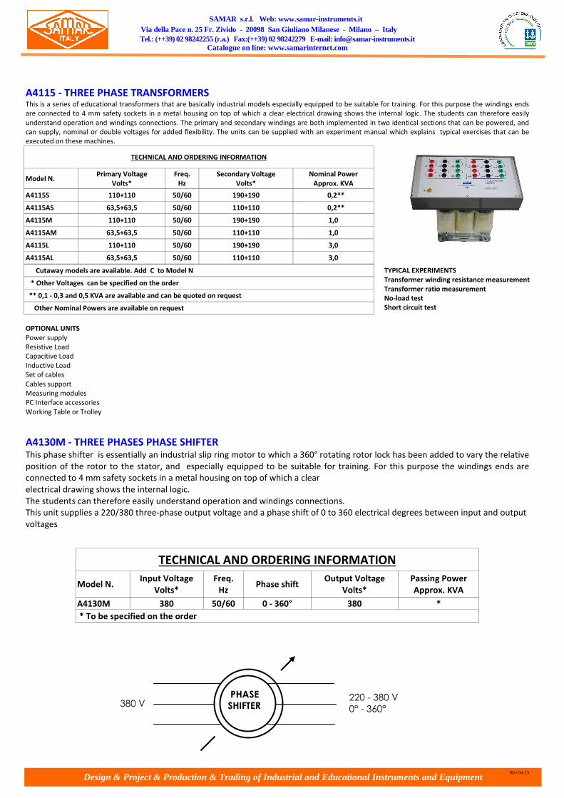
A4115 - THREE PHASE TRANSFORMERS This is a series of educational transformers that are basically industrial models especially equipped to be suitable for training. For this purpose the windings ends
are connected to 4 mm safety sockets in a metal housing on top of which a clear electrical drawing shows the internal logic. The students can therefore easily
understand operation and windings connections. The primary and secondary windings are both implemented in two identical sections that can be powered, and
can supply, nominal or double voltages for added flexibility. The units can be supplied with an experiment manual which explains typical exercises that can be
executed on these machines.
TECHNICAL AND ORDERING INFORMATION
Model N. Primary Voltage
Volts*
Freq.
Hz
Secondary Voltage
Volts*
Nominal Power
Approx. KVA
A4115S 110+110 50/60 190+190 0,2**
A4115AS 63,5+63,5 50/60 110+110 0,2**
A4115M 110+110 50/60 190+190 1,0
A4115AM 63,5+63,5 50/60 110+110 1,0
A4115L 110+110 50/60 190+190 3,0
A4115AL 63,5+63,5 50/60 110+110 3,0
Cutaway models are available. Add C to Model N
* Other Voltages can be specified on the order
** 0,1 - 0,3 and 0,5 KVA are available and can be quoted on request
Other Nominal Powers are available on request
OPTIONAL UNITS
Power supply
Resistive Load
Capacitive Load
Inductive Load
Set of cables
Cables support
Measuring modules
PC Interface accessories
Working Table or Trolley
A4130M - THREE PHASES PHASE SHIFTER This phase shifter is essentially an industrial slip ring motor to which a 360° rotating rotor lock has been added to vary the relative
position of the rotor to the stator, and especially equipped to be suitable for training. For this purpose the windings ends are
connected to 4 mm safety sockets in a metal housing on top of which a clear
electrical drawing shows the internal logic.
The students can therefore easily understand operation and windings connections.
This unit supplies a 220/380 three-phase output voltage and a phase shift of 0 to 360 electrical degrees between input and output
voltages
TECHNICAL AND ORDERING INFORMATION
Model N. Input Voltage
Volts*
Freq.
Hz Phase shift
Output Voltage
Volts*
Passing Power
Approx. KVA
A4130M 380 50/60 0 - 360° 380 *
* To be specified on the order
TYPICAL EXPERIMENTS
Transformer winding resistance measurement
Transformer ratio measurement
No-load test
Short circuit test
380 V 220 - 380 V
0° - 360°
PHASE
SHIFTER

Design & Project & Production & Trading of Industrial and Educational Instruments and Equipment
SAMAR s.r.l. Web: www.samar-instruments.it Via della Pace n. 25 Fr. Zivido - 20098 San Giuliano Milanese - Milano – Italy Tel.: (++39) 02 98242255 (r.a.) Fax:(++39) 02 98242279 E-mail: [email protected]
Catalogue on line: www.samarinternet.com
Rev 04.15
BRAKES
A4410 - MAGNETIC POWER BRAKE This magnetic powder brake consists of a stator with an energising coil, an internal rotor and magnetic iron powder between them. The field generated by the
current flowing in the coil "solidifies" the magnetic powder iron that mechanically connects the rotor to the stator with a force that is proportional to the amount
of current. Therefore, by varying the energising current it is possible to vary the braking action. The torque may be displayed by the Torque Meter Model A4730
fitted with Load Cell Model A4731. Optional Arm Weights and Counterweights, Model A47AW, can be supplied if an electronic torque measurement is not
available.
OPTIONAL ACCESSORIES: A44AW Arms weights and counterweights
OPTIONAL UNITS
Power Supply
Torque Meter
Load Cell
Coupling Base
Set of Cables
Cables Support
PC Interface Accessories
Working Table or Trolley
A4420 - EDDY CURRENT BRAKES This is a series of brake trainers specially designed for braking and measuring torque of all rotating machines in a school laboratory environment. They are
equipped with 4mm terminals. The torque may be displayed by the Torque Meter Model. A4730 fitted with Load Cell Model A4731. Optional Arm Weights and
Counterweights, Model A44AW, can be supplied if an electronic torque measurement is not available.
OPTIONAL ACCESSORIES:
A42DS Double shaft
A4280 Tachogenerator already mounted on the machine (or external, to be specified when ordering)
A44AW Arms weights and counterweights
A4840RL Rotor locker
TECHNICAL AND ORDERING INFORMATION
Model N. A4410S
(B650)
A4410M
(B2500)
A4410L
(B5000)
Maximum Torque, Nm 65 250 500
Nominal Voltage, V 24 24 24
Nominal Current, A 0.95 1.1 0.9
Coil Resistance at 20°C, Ω 24 22 27
Max. Dissipated Power, W 200 600 1600
Weight, Kg 6.5 32 59
TECHNICAL SPECIFICATIONS
Model N. Input Voltage
Volts DC
Nominal Speed
RPM*
Nominal Power
Approx Kw
A4420S 0-90 3.000 0,3
A4420M 0-90 3.000 1,0
A4420L 0-90 3.000 3,0
* 1.500 RPM are available and can be quoted on request. Add 4 to model number
OPTIONAL UNITS:
Power Supply
Torque Meter
Load Cell
Coupling base
Flywheel
Set of cables
Cables support
PC Interface accessories
Working table or Trolley

Design & Project & Production & Trading of Industrial and Educational Instruments and Equipment
SAMAR s.r.l. Web: www.samar-instruments.it Via della Pace n. 25 Fr. Zivido - 20098 San Giuliano Milanese - Milano – Italy Tel.: (++39) 02 98242255 (r.a.) Fax:(++39) 02 98242279 E-mail: [email protected]
Catalogue on line: www.samarinternet.com
Rev 04.15
A4430 - BRAKING DC GENERATORS This is a series of brake generators trainers specially designed for braking and measuring torque of all rotating machines in a school laboratory environment. The
units are very versatile and can also be used as DC Motors and Generators. They are equipped with an Educational Terminal Board with 4mm terminals and a clear
synoptic showing the feasible connections. The torque may be displayed by the Torque Meter Model A4730 fitted with Load Cell Model A4731. Optional Arm
Weights and Counterweights, Model A47AW, can be supplied if an electronic torque measurement is not available.
OPTIONAL ACCESSORIES:
A42DS Double shaft
A44AW Arms weights and counterweights
A4430R - VARIABLE LOAD FOR BRAKE GENERATOR
The brake generator load is a variable resistive load to be used with the brake generators. It is dedicated for this use and more
simple compared with the series A45 loads.
Specifications
Input Voltage 220V to 240 V
Nominal power 300 W (series S) / 1200 W (series M) / 3600 W (series L)
OPTIONAL UNITS:
Power Supply
Resistive Load
Excitation Rheostat
Speed Meter
Torque Meter
Load Cell
Coupling base
Flywheel
Set of cables
Cables support
PC Interface accessories
Working table or Trolley
TECHNICAL SPECIFICATIONS
Model N. Output Voltage
Volts DC*
Excitation Voltage
Volts DC*
Nominal Speed
RPM**
Nominal Power
Approx. Kw***
A4430S 220 220 3.000 0,3
A4430M 220 220 3.000 1,0
A4430L 220 220 3.000 3,0
* 230 or 240V are available. Specify on Order.
** 1.500 RPM are available and can be quoted on request. Add 4 to model number
*** 0,1 - 0,3 - 0,5 and 3,5 KW are available and can be quoted on request..
NOTE: Powers are indicative and reflect the ranges of the industry standards.

Design & Project & Production & Trading of Industrial and Educational Instruments and Equipment
SAMAR s.r.l. Web: www.samar-instruments.it Via della Pace n. 25 Fr. Zivido - 20098 San Giuliano Milanese - Milano – Italy Tel.: (++39) 02 98242255 (r.a.) Fax:(++39) 02 98242279 E-mail: [email protected]
Catalogue on line: www.samarinternet.com
Rev 04.15
LOADS STANDARD RLC LOADS Dimensions: 1000 x 300 x 350 mm (type RLC)
Available powers: 200 VA/VAR, 1000 VA/VAR, 3000 VA/VAR (on request different powers from the ones
shown).
Regulation by Step with separated powers on each phase
Use: single-phase and three-phase, possibility of connection star / delta
Nominal voltage 220/380 V
Panel equipped with security clamps and synoptic
AVAILABLE LOADS ONLY RESISTIVE OR ONLY CAPACITIVE OR ONLY INDUCTIVE Same powers and characteristic as the model described above. (on request custom executions)
RESISTIVE LOADS
Available powers: 200 VA, 1000 VA, 3000 VA (on request different powers)
Regulation by Step with separated powers on each phase
Use: single-phase and three-phase, possibility of connection star / delta
Nominal voltage 220/380 V
Panel equipped with security clamps and synoptic
CAPACITIVE LOADS
Available powers: 200 VAR, 1000 VAR, 3000 VAR (on request different powers)
Regulation by Step with separated powers on each phase
Use: single-phase and three-phase, possibility of connection star / delta
Nominal voltage 220/380 V
Panel equipped with security clamps and synoptic
INDUCTIVE LOADS
Available powers: 200 VAR, 1000 VAR, 3000 VAR (on request different powers)
Regulation by Step with separated powers on each phase
Use: single-phase and three-phase, possibility of connection star / delta
Nominal voltage 220/380 V
Panel equipped with security clamps and synoptic
PROGRAMMABLE MONO AND THREE-PHASE RLC LOAD Type RLC/1K-P Dimensions: 1000 x 300 x 350 mm
Weight: 20 Kg
Three-phase load balanced with connection to star with neutral accessible suitable also for use in single-phase
Maximum line tension 380 V with nominal power
P = 1000 W with 4 steps each 250 W
Qx = 1000 VAR 4 steps each 250 W
Qc = 1000 VAR 4 steps each 250 W
The load is supplied with manual/automatic switch and switches for the manual insertion of the elements R, L, C.
On request various programmable power loads
OPTION trolley for loads
Comfortable and practical trolley to lodge loads of several types for easy and practical shifting
Provided with housing for accessories.
Several models and measurements are available.
ON REQUEST SPECIAL LOADS OF SEVERAL POWERS AND DIMENSIONS A few examples:
- Load for tests on switches in compliance
with IEC 1058-1 (simulates capacitive
loads)
- Load for tests on switches in compliance
with 1058-2 (simulates tungsten filament
lamps)
- Load of ant inductive resistors for the
discharge B.T lamp simulation.
- Load of ant inductive resistors for the
discharge AT lamp simulation. (For
luminous signboards)
- Capacitive load suitable for the test in field
of the single-phase limiting device
switches installed on the electric energy
meters.

Design & Project & Production & Trading of Industrial and Educational Instruments and Equipment
SAMAR s.r.l. Web: www.samar-instruments.it Via della Pace n. 25 Fr. Zivido - 20098 San Giuliano Milanese - Milano – Italy Tel.: (++39) 02 98242255 (r.a.) Fax:(++39) 02 98242279 E-mail: [email protected]
Catalogue on line: www.samarinternet.com
Rev 04.15
DESKTOP POWER SUPPLY
MULTIFUNCTION SINGLE-THREE PHASE POWER SUPPLY TYPE RZ01 Designed to be used in laboratory and for supplying fixed and variable d.c. and a.c. feedings necessary to make experiences. Complete of all safety devices established by Standards.
Supplied with a certification that declares quality and compliance with EN61010 Standard. Built in metal case with frontal panel having a clear synoptic of the various functions.
Painting according to standards of security and good quality. Guaranteed against rust and scratches. The turret can be opened at the rear and at front in order to make inspections
and maintenance . Terminals according to safety rules 4 mm protected against casual contacts.
Dimensions: 1000x400x350 mm
Feeding 400 V three-phase + N + PE 50 Hz (ON DEMAND: different power supply)
ON DEMAND: additional securities: coverings in polycarbonate of the frontal side.
GENERAL CHARACTERISTICS
SAFETY SECTION:
• Emergency mushroom button
• Automatic residual current circuit breaker
• Starting Key
• Signal lamp
• Protection fuses at OUTPUT SECTION (on request magnetothermic)
OUTPUTS
• 3 fixed universal single-phase outlets 220 V 10/16 A
• 1 three-phase fixed outlet + N + T 380 V (on request, different configuration )
• 1 adjustable three-phase output 0– 500 V / 5A
• 1 adjustable single-phase output 0 – 250 V / 5 A·
• 1 adjustable d.c. rectified output 0 – 250 V / 5 A
• 1 stabilized adjustable power supply 0 – 30 V / 0 – 5 A ( ON REQUEST: different outputs or dual version, three-outputs and so on )
Complete of:·
• Digital instrument 3 ½ digits that indicates d.c. rectified output voltage
• Digital instruments 3 ½ digits that indicate voltage and current supplied by stabilized power supply·
• Digital instruments 3 ½ digits that indicate single-phase and three-phase output voltage selected by switch. Switch to select single-phase or three-
phase output.
POWER SUPPLY SERIES A0240 FOR ELECTRICAL MACHINES – POWER 200W or 1KW or 3KW (on request other powers) Designed to be used in electrical laboratory for supplying fixed and variable d.c. and a.c. feedings necessary to make experiences. Complete of all safety devices
established by standards. Supplied with a certification that declares quality and compliance with EN61010 Standard. Built in metal case with frontal panel
having a clear synoptic of the various functions. Painting according to Standards of security and good quality. Guaranteed against rust and scratches. The turret
can be opened at the rear and at front in order to make inspections and maintenance . Terminals according to safety rules 4 mm protected against casual
contacts. General and outputs protections guarantee the user and the unit against misuse and/or faulty operation. A.c. and d.c. outputs are variable with
continuity and the values of current and voltage are suitable for machines under test. Each output is equipped with digital instrument. Terminals according to
safety rules.
Dimensions: 1000x400x350 mm
Feeding 400 V three-phase + N + PE 50 Hz (ON DEMAND: different power supply)
ON DEMAND: additional securities: coverings in polycarbonate of the frontal side.
GENERAL CHARACTERISTICS
SAFETY SECTION:
Emergency mushroom button
Automatic residual current circuit breaker
Starting Key
Signal lamp
OUTPUTS
POWER: available version 200W or 1KW or 3KW (on request other powers)
Three-phase adjustable output: 0-440 V/0-250 V a.c. (current depends on the power you choose)
Single-phase adjustable output: 0-220 V a.c./d.c. (current depends on the power you choose)
Single-phase adjustable output: 0-220 V d.c./1 A (current depends on the power you choose)
Three-phase fixed output 380 V 13 A with EEC plug
N. 2 Single-phase fixed output 220 V 16 A with Shuko plug or universal type
differential magnetothermic protection high sensitivity 4 x 20 mA button, terminals according to safety rules interconnected by means of a synoptic, measuring
instruments on the outputs and protection of max speed rotation of motors.
Complete of:
• Switch to select single-phase or three-phase output. Different three-phase output voltage selected by switch.
• Start/stop button
• Signal lamp
• Digital instruments 3 ½ digits that indicate voltage and current single-phase and three-phase output selected by switch. Magnetothermic protection for
a.c. line and d.c. line
• Digital instruments 3 ½ digits that indicates d.c. rectified output voltage and current, protection with magnetothermic protection

Design & Project & Production & Trading of Industrial and Educational Instruments and Equipment
SAMAR s.r.l. Web: www.samar-instruments.it Via della Pace n. 25 Fr. Zivido - 20098 San Giuliano Milanese - Milano – Italy Tel.: (++39) 02 98242255 (r.a.) Fax:(++39) 02 98242279 E-mail: [email protected]
Catalogue on line: www.samarinternet.com
Rev 04.15
Programmable power supplies Type VAE/1 (code 1385) and VAE/2 (code 1386) They allow regulating the test voltage controlled from PC ensuring such a perfect linearity for a better
optimisation of tests. Each model includes two three-phase variacs with adjustable separately outputs
single-phase and three-phase voltages in d.c. and a.c. and driven by motors through RS232 of PC .
Possibilities of local control by buttons. Included two digital instruments 3 ½ digits for the reading of the
supplied voltage, two insulation transformers for separation of the output voltage and switch to reduce the
output voltage to 1/10 of the nominal voltage. Power supplies 3x380 V. Provided with safety devices.
Dimensions: 800x600x1000 mm. Weight 120 or 170 kg approx according to the model:
VAE/1 1200 VA for output (total 2400 VA)
VAE/2 3200 VA for output (total 6400 VA).
For both models:
adjustable output dc voltage from 0 to 250 V;
adjustable three phase output voltage from 0 to 400 V with possibility of single-phase use.
On request other output voltage or powers. On request also not programmable versions.
WORKBENCH TYPE TU200
The workbench is suitable to satisfy the laboratory requests in the various sectors of the school.
• Standard dimensions mm 2000x1000x900h (ON DEMAND: other dimensions).
• Tubular structures mm 40x40x2
• Wooden plane covered on both sides in plastic laminated with anti-scratch work plane.
• Rounded corners bordered in rubber
• Feet adjustable by screw
• Painting with epoxy thermo-hardening dust and phospho-degreasing treatment (the
bench is guaranteed against scratch and rust).
Availability of a wide range of options afterwards described that increases the versatility of the
desk. Adaptability to the various requests of the user.
OPTIONS FOR THE WORKBENCH • DRAWERS: mounted under the worktop, single or double, side by side or as a chest of drawers.
Handle and lock included.
• UNDER-POWER: powers mounted under the worktop on the short or long side of the bench
including wide range of accessories.
• UP-POWER: powers mounted on the worktop on the short or long side of the bench (in this last
case put side by side or single ) including wide range of accessories.
• SUPPORT PLACE: suitable to lodge instruments including wide range of accessories. Placed on
the worktop on the short or long side of the bench.
• POWER SUPPLY: several models are available. See the relevant leaflet for detailed descriptions
• KEYBOARD HOLDER: extractable keyboard placed under the worktop to lodge keyboard and
mouse
• PC TOWER SUPPORT: for PC tower to be fixed under the worktop
COVER ANTI-VANDALIS

Design & Project & Production & Trading of Industrial and Educational Instruments and Equipment
SAMAR s.r.l. Web: www.samar-instruments.it Via della Pace n. 25 Fr. Zivido - 20098 San Giuliano Milanese - Milano – Italy Tel.: (++39) 02 98242255 (r.a.) Fax:(++39) 02 98242279 E-mail: [email protected]
Catalogue on line: www.samarinternet.com
Rev 04.15
MOTOR CONTROL
DC MOTOR CONTROL TYPE REG/CC
ELECTRONIC MODULE OF SPEED ADJUSTMENT IN D.C.
SYSTEM OF MOTOR CONTROL FOR D.C. COMPOSED BY SPEED CONTROL BOARD FOR SERVOMOTOR OF LATEST
GENERATION
Suitable for motor 200 W or 1KW Versions with different powers are available on request.
Sizing of the actuator and of the motor in function of the dynamic characteristics of the
load
Speed control in open loop.
Speed control for operation in armature feedback
Speed control in closed loop .This is possible only by means of a d.c. motor with tacho
generator with 10 V output at max speed (not included)
Issues of stability and control PID parameters
Drives and safety
Drives and electromagnetic compatibility. Design to ensure compliance with EC
Standards.
Reduction of emissions through filters.
Ramp speed control.
Power supply: single-phase 230 V d.c
Speed: 3000 rpm
A4240 - DC COMPOUND EXCITATION MACHINES This is a series of educational motors/generators that are basically industrial models especially equipped to be suitable for training. For this purpose the windings
ends are connected to 4 mm safety sockets in a metal housing on top of which a clear electrical drawing shows the internal logic. The students can therefore easily
understand operation and windings connections. The machine has two excitation windings: one for series and one for shunt excitations.
The units can be supplied with an experiment manual which explains typical exercises that can be executed on these machines. A comprehensive set of
accessories and a joint allow easy and quick coupling with other machines or with a brake.
AVAILABLE
A4242 - DC SERIES EXCITATION MACHINES
A4244 - DC SHUNT EXCITATION MACHINES
TECHNICAL AND ORDERING INFORMATION
Model N.
Motor Input Voltage
Generator Output Voltage
Volts DC*
Excitation
Voltage
Volts DC*
Nominal Speed
RPM**
Nominal Motor Power
Approx. KW
A4240S 220 220 3.000 0,2***
A4240M 220 220 3.000 1,0
Industrial version is available. Add I to Model Number
Kit version is available. Add K to Model Number
Cutaway models are available. Add C to Model Number
* 230 or 240V or other voltages are available. Specify on Order.
** 1.500 RPM are available and can be quoted on request. Add 4 to Model N.
*** 0,1 - 0,3 and 0,5 KW are available and can be quoted on request.
NOTE: Powers are indicative and reflect the ranges of the industry standards

Design & Project & Production & Trading of Industrial and Educational Instruments and Equipment
SAMAR s.r.l. Web: www.samar-instruments.it Via della Pace n. 25 Fr. Zivido - 20098 San Giuliano Milanese - Milano – Italy Tel.: (++39) 02 98242255 (r.a.) Fax:(++39) 02 98242279 E-mail: [email protected]
Catalogue on line: www.samarinternet.com
Rev 04.15
AC MOTOR CONTROL TYPE REG/CA
ELECTRONIC MODULE OF SPEED ADJUSTMENT IN A.C. OPEN AND CLOSED LOOP System composed by an inverter of latest generation that is able to manage the motor in all its controls.
The installation of the sensors on the motor is not necessary
Suitable for motors of 200 W.
Versions with different powers are available on request
Experiences that can be made:
Speed control motor in open loop by adjusting the supplied frequency.Speed control in
open loop with the slip compensation.
Self calibration (the converter automatically acquires the motor’s parameters)
Speed control in closed loop (only with a.c. motor with tacho generator with 10 V
output at max speed not included), PID parameter setting, issues of stability
The motor to be tested is protected automatically: by means of current limitation and
by means of thermal image.
Braking by means of d.c. current
Drives and safety cautions. Designing of safety system.
Drives and electromagnetic compatibility. Design to ensure compliance with EC
Standards. Reduction of emissions by filters.
Ramp speed control.
Supplied with RS-485 output and software. Power supply: three-phase 380 V
The motor to be tested is protected automatically: by means of current limitation and by means of thermal image.
Braking by means of d.c. current
Drives and safety cautions. Designing of safety system.
Drives and electromagnetic compatibility. Design to ensure compliance with EC Standards. Reduction of emissions by filters.
Three-phase asynchronous cage motor (on request)
Power 200 W -Speed 3000 rpm
Star/delta connection
A4220 - SQUIRREL CAGE THREE PHASE MOTORS This is a series of educational motors that are basically industrial models especially equipped to be suitable for training. For this purpose the windings ends are
connected to 4 mm safety sockets in a metal housing on top of which a clear electrical drawing shows the internal logic. The students can therefore easily
understand operation and windings connections that can be configured for STAR or DELTA schemes. The units can be supplied with an experiment manual which
explains typical exercises that can be executed on these machines. A comprehensive set of accessories and a joint allow easy and quick coupling with other
machines or with a brake.
TECHNICAL AND ORDERING INFORMATION
Model N. Input Voltage
Volts (∆/Y)
Freq.
Hz
Nominal Speed
Approx. RPM*
Nominal Power
Approx. KW
A4220S 220/380** 50 3.000 0,2***
A4220AS 127/220 60 3.600 0,2***
A4220M 220/380** 50 3.000 1,1
A4220AM 127/220 60 3.600 1,1
Industrial version is available. Add I to Model Number
Kit versions are available. Add K to Model Number
Cutaway models are available. Add C to Model Number
* Four Poles Motors are available. Add 4 to Model N. (Ex. A4220AS/4)
** 230/400V and 240/415V are available. Specify on order
*** 0,1 - 0,3 and 0,5 KW are available and can be quoted on request.
NOTE: Powers are indicative and reflect the ranges of the industry
standards.
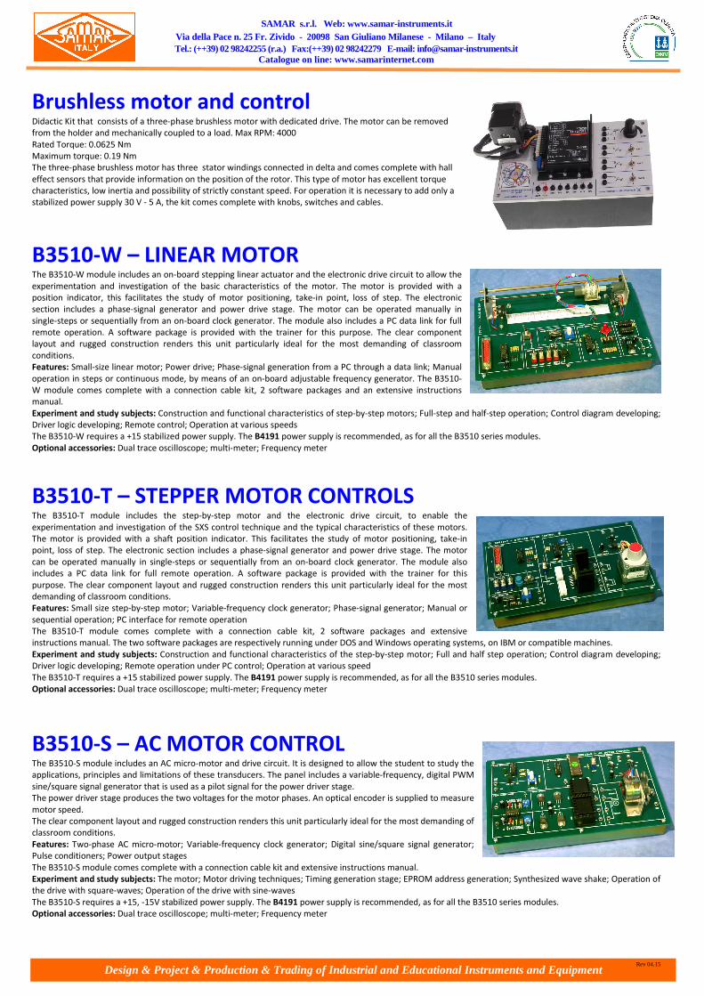
Design & Project & Production & Trading of Industrial and Educational Instruments and Equipment
SAMAR s.r.l. Web: www.samar-instruments.it Via della Pace n. 25 Fr. Zivido - 20098 San Giuliano Milanese - Milano – Italy Tel.: (++39) 02 98242255 (r.a.) Fax:(++39) 02 98242279 E-mail: [email protected]
Catalogue on line: www.samarinternet.com
Rev 04.15
Brushless motor and control Didactic Kit that consists of a three-phase brushless motor with dedicated drive. The motor can be removed
from the holder and mechanically coupled to a load. Max RPM: 4000
Rated Torque: 0.0625 Nm
Maximum torque: 0.19 Nm
The three-phase brushless motor has three stator windings connected in delta and comes complete with hall
effect sensors that provide information on the position of the rotor. This type of motor has excellent torque
characteristics, low inertia and possibility of strictly constant speed. For operation it is necessary to add only a
stabilized power supply 30 V - 5 A, the kit comes complete with knobs, switches and cables.
B3510-W – LINEAR MOTOR The B3510-W module includes an on-board stepping linear actuator and the electronic drive circuit to allow the
experimentation and investigation of the basic characteristics of the motor. The motor is provided with a
position indicator, this facilitates the study of motor positioning, take-in point, loss of step. The electronic
section includes a phase-signal generator and power drive stage. The motor can be operated manually in
single-steps or sequentially from an on-board clock generator. The module also includes a PC data link for full
remote operation. A software package is provided with the trainer for this purpose. The clear component
layout and rugged construction renders this unit particularly ideal for the most demanding of classroom
conditions.
Features: Small-size linear motor; Power drive; Phase-signal generation from a PC through a data link; Manual
operation in steps or continuous mode, by means of an on-board adjustable frequency generator. The B3510-
W module comes complete with a connection cable kit, 2 software packages and an extensive instructions
manual.
Experiment and study subjects: Construction and functional characteristics of step-by-step motors; Full-step and half-step operation; Control diagram developing;
Driver logic developing; Remote control; Operation at various speeds
The B3510-W requires a +15 stabilized power supply. The B4191 power supply is recommended, as for all the B3510 series modules.
Optional accessories: Dual trace oscilloscope; multi-meter; Frequency meter
B3510-T – STEPPER MOTOR CONTROLS The B3510-T module includes the step-by-step motor and the electronic drive circuit, to enable the
experimentation and investigation of the SXS control technique and the typical characteristics of these motors.
The motor is provided with a shaft position indicator. This facilitates the study of motor positioning, take-in
point, loss of step. The electronic section includes a phase-signal generator and power drive stage. The motor
can be operated manually in single-steps or sequentially from an on-board clock generator. The module also
includes a PC data link for full remote operation. A software package is provided with the trainer for this
purpose. The clear component layout and rugged construction renders this unit particularly ideal for the most
demanding of classroom conditions.
Features: Small size step-by-step motor; Variable-frequency clock generator; Phase-signal generator; Manual or
sequential operation; PC interface for remote operation
The B3510-T module comes complete with a connection cable kit, 2 software packages and extensive
instructions manual. The two software packages are respectively running under DOS and Windows operating systems, on IBM or compatible machines.
Experiment and study subjects: Construction and functional characteristics of the step-by-step motor; Full and half step operation; Control diagram developing;
Driver logic developing; Remote operation under PC control; Operation at various speed
The B3510-T requires a +15 stabilized power supply. The B4191 power supply is recommended, as for all the B3510 series modules.
Optional accessories: Dual trace oscilloscope; multi-meter; Frequency meter
B3510-S – AC MOTOR CONTROL The B3510-S module includes an AC micro-motor and drive circuit. It is designed to allow the student to study the
applications, principles and limitations of these transducers. The panel includes a variable-frequency, digital PWM
sine/square signal generator that is used as a pilot signal for the power driver stage.
The power driver stage produces the two voltages for the motor phases. An optical encoder is supplied to measure
motor speed.
The clear component layout and rugged construction renders this unit particularly ideal for the most demanding of
classroom conditions.
Features: Two-phase AC micro-motor; Variable-frequency clock generator; Digital sine/square signal generator;
Pulse conditioners; Power output stages
The B3510-S module comes complete with a connection cable kit and extensive instructions manual.
Experiment and study subjects: The motor; Motor driving techniques; Timing generation stage; EPROM address generation; Synthesized wave shake; Operation of
the drive with square-waves; Operation of the drive with sine-waves
The B3510-S requires a +15, -15V stabilized power supply. The B4191 power supply is recommended, as for all the B3510 series modules.
Optional accessories: Dual trace oscilloscope; multi-meter; Frequency meter

Design & Project & Production & Trading of Industrial and Educational Instruments and Equipment
SAMAR s.r.l. Web: www.samar-instruments.it Via della Pace n. 25 Fr. Zivido - 20098 San Giuliano Milanese - Milano – Italy Tel.: (++39) 02 98242255 (r.a.) Fax:(++39) 02 98242279 E-mail: [email protected]
Catalogue on line: www.samarinternet.com
Rev 04.15
B3510-G – DC MOTOR SPEED CONTROL The B3510-G module incorporates all the sub-systems necessary for the study of DC motor speed control in both
open and closed-loop set-ups. The module has two small DC motors ganged together. One is used as the drive
motor and the other as a tachometric generator. A slot-type optical feedback sensor is also mechanically ganged
to a DC motor. The small motors ensure safe operation in all circumstances, this is important when the student
has little experience.
The clear component layout and rugged construction renders this unit particularly ideal for the most demanding
of classroom conditions.
Features: 2 small-size mechanically ganged DC motors. One of the two operates as a tachometric generator, or as
a load; Slot-type optical sensor and encoder disk. This arrangement provides 8 pulses per motor revolution.;
Frequency-to-voltage converter for the encoder signal; Tacho-generator signal conditioner; DC reference
generator; Loop amplifier with adjustable gain; Switch mode power driver for the motor
The B3510-G board comes complete with a connection cable kit and extensive instructions manual.
Exercises and study subjects: Open and closed-loop speed control; Speed sensors: encoders and tacho-generators; Adjustment of gain in a closed-loop system;
System response versus loop-gain; Operation of a power switch mode driver
The B3510-G requires a +15, -15V stabilized power supply. The B4191 power supply is recommended, as for all the B3510 series modules.
Optional accessories: Dual trace oscilloscope; multi-meter
B3510-P – ROTATIONAL POSITION ENCODERS The B3510-P module is an educational version of an industrial type optical encoder. This allows the student to
study the function and use of this type of device
The clear component layout and rugged construction renders this unit particularly ideal for the most demanding
of classroom conditions.
Features: Hand-driven rotating transparent plastic disk, which has darkened (blinded) segments and sectors, that
obscure a set of 5 phototransistors placed beneath the disk; The encoder is illuminated by a set of 5 LED lamps
from above; Absolute decoder, with a 7-segments display; Relative decoder; Up/down step counting logic and
display; Reset pushbutton; The relative encoder circuit is also equipped with step doubler and quadrupler and
relevant display (micro steps)
The B3510-P module comes complete with a connection cable kit and extensive instructions manual.
Experiment and study subjects: The items of this module are of a quite general use in the industry. The student is
made to become quickly acquainted with their principle of operation, characteristics and limits of use.
The B3510-P requires a +15 stabilized power supply. The B4191 power supply is recommended, as for all the B3510 series modules.
Optional accessories: Dual trace oscilloscope; multi-meter
B3510-J – POSITION CONTROL This module includes a geared DC motor (approx. 1 revolution per second), which operates a screw-driven
mechanism, ganged to the slide of a linear potentiometer. A second linear potentiometer allows the setting the
reference position. This set-up enables the student to study the benefits and limitations of a closed-loop position
control system. The clear component layout and rugged construction renders this unit particularly ideal for the
most demanding of classroom conditions.
Features: Mechanically simulated position system; Summing node for the reference and feedback signals; Loop
amplifier, gain-adjustable; Power amplifier/DC driver; Power supply conditioner and control circuit
The B3510-J module comes complete with a connection cable kit and extensive instructions manual.
Experiments and study subjects: Characteristics of various transducers: linear potentiometer and gear motor; Set-
up of a linear position control system; System response versus loop gain; Practical safety precautions for position
systems: run limits, power supply control and motor switch off to prevent motor stall
The B3510-J requires a +15, -15V stabilized power supply. The B4191 power supply is recommended, as for all the B3510 series modules.
Optional accessories: Dual trace oscilloscope; multi-meter
AUTOMATION FOR SLIDING AND SWING GATES
TYPE CANC/SIM
require dedicated catalogue
The trainer includes all the necessary for the working:
• Gate with hinged door and sliding door and accessories
• Opening motors
• Selector
• Control unit
• Flashing light Radio kit (one for type of gate), transmitter,
photocells, complete set of accessories
• Equipped with manuals and exercises
OPTION
• Simulator of breakdowns through micro switch.
On request types only hinged door or only sliding door

Design & Project & Production & Trading of Industrial and Educational Instruments and Equipment
SAMAR s.r.l. Web: www.samar-instruments.it Via della Pace n. 25 Fr. Zivido - 20098 San Giuliano Milanese - Milano – Italy Tel.: (++39) 02 98242255 (r.a.) Fax:(++39) 02 98242279 E-mail: [email protected]
Catalogue on line: www.samarinternet.com
Rev 04.15
APPLICATION WITH PLC
PLC AND SCADA ACQUISITION MODULE AND CONTROLS SCADA The system consists of data acquisition module and terminal boards with clear educational synoptic for easy wiring and
programming.
The kit includes:
1 Port COM RS23 - 1 port MiniUSB Processor NXP LPC2387
6 digital isolated input (1 counter 10 kHz) - 2 analog Input 0-10Vdc - 4 digital isolated Output Relè
1 expansion bus I2C High-speed, 16 digital input, 8 digital Output, 5 analog input, 4 analog output
programming tool included,
Programming cable
220/12 V Adapter
Software Programming Ladder Diagram (LD), Instruction List (IL) / C language, SCADA SOFTWARE
Option :
• Touch screen LCD Display
• Ethernet port for local network/internet connection
• I/O simulator with switch push button and LEDS
possibility of using other PLC of your choice
Motor control simulator type CONTMOT / SIM
Simulator for motor control panel with synoptic including :
N. 4 contactors, N. 1 thermal relay, N. 4 signal lamps, N. 4 buttons (forward, reverse,
stop, emergency), No 1 tachometer 3 ½ digits with sensor mounted on the motor
with two selectable alarms, N. 1 Three-phase cage induction motor 42V - 200W, N. 1
three-phase transformer 380/42 V.
It is required a PLC with at least 8 inputs and 8 outputs. The simulator allows to start
the motor star / delta in rotation braking version.

Design & Project & Production & Trading of Industrial and Educational Instruments and Equipment
SAMAR s.r.l. Web: www.samar-instruments.it Via della Pace n. 25 Fr. Zivido - 20098 San Giuliano Milanese - Milano – Italy Tel.: (++39) 02 98242255 (r.a.) Fax:(++39) 02 98242279 E-mail: [email protected]
Catalogue on line: www.samarinternet.com
Rev 04.15
B3729-H – STAR/DELTA CIRCUIT The B3729-H simulator module replicates in a scaled and simplified manner the classic star-delta switching circuit.
This system is often used in practice to start large AC electric motors with heavy loads. The principle is to initially
connect the motor 3-phase windings in STAR mode, thus reducing the starting current.
After a few seconds the connection is changed to DELTA and the motor can then accelerate the load to its full
speed. The panel includes three pushbutton switches, which are available as inputs to the PLC. The simulated
switching circuit consists of four power contactors, represented by the lighting of the four LED lamps positioned
close to the symbol of the contactor on the front face of the unit. The LEDs are controlled by four assigned outputs
of the PLC.
The condition of the four contactors can be monitored by their respective auxiliary contacts indicated on the
synoptic drawing. These contacts are available as inputs to the PLC. The result of the various operations performed
by the PLC is indicated by the four LEDs situated in the lower part of the board.
B3729-H is supplied with a Sample Program. The students can investigate the functions of the simulator using this program, and can also develop their own
programs using the software supplied with the PLC MACHINE.
The unit comes complete with a sample program and an extensive instructions manual.
It can also be used with any suitable PLC machine, which may already be possessed by the teaching institute. The B3729-DX should be used as an interface in all
cases.
B3729-I – ROTOR RESISTANCE STARTER CIRCUIT The B3729-I simulator module replicates in a scaled and simplified manner a rotor resistance starter circuit. This
system is often used in practice to reduce the overload while starting and launching large AC asynchronous electric
motors. These motors have the rotor made of a winding, creating a magnetic circuit.
The winding is initially connected to a (relatively) high resistance, which is progressively reduced in steps to a null
value (short circuit). Due to the properties of the magnetic interaction between rotor and stator, this reduces the
current required for starting. The panel includes two pushbutton switches, which are available as inputs to the PLC.
The simulated starter circuit consists of five power contactors, represented by the lighting of the five LED lamps
positioned close to the symbol of the contactor on the front face. The LEDs are controlled by five assigned outputs
of the PLC. The condition of the five contactors can be monitored by their respective auxiliary contacts indicated on
the synoptic drawing. These contacts are available as inputs to the PLC.
B3729-I is supplied with a Sample Program. The students can investigate the functions of the simulator using this program, and can also develop their own
programs using the software supplied with the PLC MACHINE. The unit comes complete with a sample program and an extensive instructions manual.
B3601 – INDUSTRIAL ELECTRONICS TRAINER The trainer is conceived to present a review of the characteristics and use of important industrial devices for power handling/conversion, up to application
examples of special interest in comprehensive manner. The trainer consists of a collection of box-like modules, 100 x 160 x 20mm size, with a magnetic base and a
printed circuit board front face. The PCB face includes the components and devices needed to perform the experiments, with clear silkprint indicating the
component symbols, identities and interconnections.For the execution of the experiments the modules are placed on a metallic Base plate (430 x 310 x 30mm)
where they are retained by the magnetic strips. The connections to the power supply and to the measuring instruments is by plug-in cables. Certain experiments
require more than a single module to be interconnected. This is also done by plug-in cables. The magnetic latching of the modules to the metallic Base plate
ensures that the various items remain steadily fixed even if the Base plate is placed vertically, as in case of collective demonstrations by the Instructor. The trainer
includes an Auxiliary Module with the low-voltage DC and AC sources required to perform the experiments. This module also includes resistive and inductive loads.
All the experiment modules are designed to work from the low-voltages (18-36V AC and 15 to 48V DC) for increased safety. This makes the trainer especially
suitable for use by students in their early stages of training, when they have not yet gained the confidence required to work on industry-standard high-voltage
systems.
Features: Auxiliary module (with power supplies and loads). Base plate. 4-Diodes
module. Capacitors module. 4-Thyristors module. Setpoint generator. 4-Pulse
thyristor firing unit. Single-phase Burst AC controller. TRIAC application module. Self-
commutation chopper. Temperature control module. Switching regulator module.
PWM chopper/inverter. DC motor (permanent magnet type).
Study topics
Uncontrolled rectifiers:
Half-wave rectifier. Half-wave rectifier with capacitor. Half-wave rectifier with
inductive load. Half-wave rectifier with filter. Midpoint full-wave rectifier. Full-wave
rectifier with capacitor. Full-wave rectifier with inductive load. Full-wave rectifier
with filter. Diode bridge rectifier. Voltage doubler
Controlled rectifiers: Half-wave controlled rectifier. Midpoint full-wave controlled
rectifier. Controlled single-phase bridges. AC power control with thyristors. AC and
DC power control with TRIAC
Application examples: Temperature control. The AC burst controller. The
temperature control module. Setup of a temperature control systems
DC-DC conversion: The self-commutation chopper. The switching regulator. The
PWM converter. The trainer is supplied with cable and accessories kit, Instructions
Manual and storage case for the equipment modules
Note: Test instruments and electrical machines are to be ordered separately

Design & Project & Production & Trading of Industrial and Educational Instruments and Equipment
SAMAR s.r.l. Web: www.samar-instruments.it Via della Pace n. 25 Fr. Zivido - 20098 San Giuliano Milanese - Milano – Italy Tel.: (++39) 02 98242255 (r.a.) Fax:(++39) 02 98242279 E-mail: [email protected]
Catalogue on line: www.samarinternet.com
Rev 04.15
AUTOMATED ELECTRICAL MEASUREMENTS Data acquisition system in electrical measurements and
electrical machinery of any power and electrical characteristics
SERIES ETC
WIRELESS INTERFACE
We propose several trainers dedicated to the study of various electrical machines and power measurements in a three-phase
system ARON. Includes WIRELESS interface and software that guides the user step by step.
Ability to connect the system to LIM and TABLET for a modern
teaching and sharing of tests performed.
TRAINER WIRELESS SINGLE PHASE TRANSFORMER Type ETCW/TM
terminal according accident prevention
The system includes:
- Module measuring instruments: digital instrumentss 4 digits 10,000 points, precision ac
0.5%, interface wireless.Tipo MS / TRTRMON
V1 - measure dc and ac range 100V - 750Vac / 1000Vdc
V2 - measure dc range 100V - 1000V dc
A1 - measure dc and ac range 1000mA - 10 A
W1- range 1000W - 10.000W
W2- range 1000W - 10.000W
A4110S - SINGLE PHASE TRANSFORMERS
Educational transformer basically industrial models especially equipped to be suitable for training. For
this purpose the windings ends are connected to 4 mm safety sockets in a metal housing on top of which
a clear electrical drawing shows the internal logic. The students can therefore easily understand
operation and windings connections. The primary windings have a central tap to make it possible to
supply full or half of the nominal voltage. The secondary windings are implemented in two sections for
separate use or, by connecting them in series, for cumulative output voltage.
Nominal Power: 200 VA (Other Nominal Powers are available on request )
Voltage: 110-220 V 50-60 Hz (Other Voltages can be specified on the order included 24 / 48 V )
- Set of cables
accident prevention wires of varying length red and black colors for the tests
- Manual and guided experiences
- Software unlimited license
SOFTWARE SUITABLE FOR EXPERIENCES WITH SINGLE-PHASE TRANSFORMER, COMPLETE OF
CALCULATION OF CONVENTIONAL EFFICIENCY AND RELEVANT DIAGRAMS TYPE ETC-SWTM
1 Measurement of winding resistance by voltage-current method.
2 Determination of the transformation ratio with direct reading of voltage.
3 No-load test with determination of Po, Io, Cosfìo.
4 Short circuit test with determination of Pcc, Vcc, Cosfìcc.
5 Determination of the equivalent circuit and calculation of efficiency and voltage drop, according to
load variations.

Design & Project & Production & Trading of Industrial and Educational Instruments and Equipment
SAMAR s.r.l. Web: www.samar-instruments.it Via della Pace n. 25 Fr. Zivido - 20098 San Giuliano Milanese - Milano – Italy Tel.: (++39) 02 98242255 (r.a.) Fax:(++39) 02 98242279 E-mail: [email protected]
Catalogue on line: www.samarinternet.com
Rev 04.15
TRAINER WIRELESS THREE PHASE TRANSFORMER Type ETCW/TT
terminal according accident prevention
The system includes:
- Module measuring instruments: digital instrumentss 4 digits 10,000 points,
precision ac 0.5%, interface wireless.Tipo MS / TRTRTRI
V1 - measure dc and ac range 100V - 750Vac / 1000Vdc
V2 - measure dc and ac range 100V - 750Vac / 1000Vdc
A1 - measure dc and ac range 1000mA - 10 A
A2 - measure dc and ac range 1000mA - 10 A
A3 - measure dc and ac range 1000mA - 10 A
W1- range 1000W - 10.000W
W2- range 1000W - 10.000W
A4120S - THREE PHASE TRANSFORMERS Educational transformer basically industrial models especially equipped to be suitable
for training. For this purpose the windings ends are connected to 4 mm safety sockets in
a metal housing on top of which a clear electrical drawing shows the internal logic. The
students can therefore easily understand operation and windings connections. The
primary windings have a central tap to make it possible to supply full or half of the
nominal voltage. The secondary windings are implemented in two sections for separate
use or, by connecting them in series, for cumulative output voltage.
Nominal Power: 200 VA (Other Nominal Powers are available on request )
Voltage: 220-380 V 50-60 Hz (Other Voltages can be specified on the order included 24
/ 48 V )
- Set of cables
accident prevention wires of varying length red and black colors for the tests
- Manual and guided experiences
- Software unlimited license
SOFTWARE SUITABLE FOR EXPERIENCES WITH THREE-PHASE TRANSFORMER, COMPLETE OF CALCULATION OF CONVENTIONAL
EFFICIENCY AND RELEVANT DIAGRAMS TYPE ETC-SWTT
1 Measurement of winding resistance by voltage-current method.
2 Determination of the transformation ratio with direct reading of voltage.
3 No-load test with determination of Po, Io, Cosfìo.
4 Short circuit test with determination of Pcc, Vcc, Cosfìcc.
5 Determination of the equivalent circuit and calculation of efficiency and voltage drop, according to load variations.

Design & Project & Production & Trading of Industrial and Educational Instruments and Equipment
SAMAR s.r.l. Web: www.samar-instruments.it Via della Pace n. 25 Fr. Zivido - 20098 San Giuliano Milanese - Milano – Italy Tel.: (++39) 02 98242255 (r.a.) Fax:(++39) 02 98242279 E-mail: [email protected]
Catalogue on line: www.samarinternet.com
Rev 04.15
TRAINER WIRELESS AC MOTOR Type ETCW/MCA
terminal according accident prevention
The system includes:
- Module measuring instruments: digital instrumentss 4 digits 10,000 points,
precision ac 0.5%, interface wireless. Tipo MS / TRMOTTRI
V1 - measure dc and ac range 100V - 750Vac / 1000Vdc
V2 - measure dc and ac range 100V - 750Vac / 1000Vdc
A1 - measure dc and ac range 1000mA - 10 A
A2 - measure dc and ac range 1000mA - 10 A
A3 - measure dc and ac range 1000mA - 10 A
W1- range 1000W - 10.000W
W2- range 1000W - 10.000W
A4220 - SQUIRREL CAGE THREE PHASE MOTORS
Educational motors basically industrial models especially equipped to be suitable for training. For this
purpose the windings ends are connected to 4 mm safety sockets in a metal housing on top of which a
clear electrical drawing shows the internal logic. The students can therefore easily understand operation
and windings connections that can be configured for STAR or DELTA schemes.
Nominal Power 200W (Other Nominal Powers are available on request )
Voltage: 220 /380 V (Other Voltages can be specified on the order included 24 / 48 V )
Nominal Speed 2850 50 Hz
Included: Star-Delta starter
- Set of cables
accident prevention wires of varying length red and black colors for the tests
- Manual and guided experiences
- Software unlimited license
SOFTWARE SUITABLE FOR EXPERIENCES WITH ELECTRICAL MOTORS, COMPLETE OF
CALCULATION OF CONVENTIONAL EFFICIENCY AND RELEVANT GRAPHIC
REPRESENTATIONS AND CIRCULAR DIAGRAMS, WHERE NECESSARY TYPE ETC-SWM
1 Measurement of stator and rotor resistance by voltage-current method.
2 Measurement of the transformation ratio
3 No-load test with determination of Po, Io, Cosfìo.
4 Short circuit test with determination of Icc, Cosfìcc.
5 Tracing of the circular diagram and calculation of the conventional efficiency.
6 Direct test with determination of electrical and mechanical characteristics with relevant visualization by tables and diagrams.
OPTION
AC MOTOR CONTROL
TYPE REG/CA
ELECTRONIC MODULE OF SPEED ADJUSTMENT IN A.C. OPEN AND
CLOSED LOOP

Design & Project & Production & Trading of Industrial and Educational Instruments and Equipment
SAMAR s.r.l. Web: www.samar-instruments.it Via della Pace n. 25 Fr. Zivido - 20098 San Giuliano Milanese - Milano – Italy Tel.: (++39) 02 98242255 (r.a.) Fax:(++39) 02 98242279 E-mail: [email protected]
Catalogue on line: www.samarinternet.com
Rev 04.15
TRAINER WIRELESS DC MOTOR Type ETCW/MCC
terminal according accident prevention
The system includes:
- Module measuring instruments: digital instrumentss 4 digits 10,000 points,
precision ac 0.5%, interface wireless. Tipo MS / TRMOTCC
V1 - measure dc range 100V - 1000Vdc
V2 - measure dc range 100V - 1000Vdc
A1 - measure dc range 1000mA - 10 A
A2 - measure dc and ac range 1000mA - 10 A
W1- range 1000W - 10.000W
A4240 - DC COMPOUND EXCITATION MACHINES
AVAILABLE
A4242 - DC SERIES EXCITATION MACHINES
A4244 - DC SHUNT EXCITATION MACHINES
Educational motors/generators basically industrial models especially equipped to be suitable
for training. For this purpose the windings ends are connected to 4 mm safety sockets in a
metal housing on top of which a clear electrical drawing shows the internal logic. The
students can therefore easily understand operation and windings connections. The machine
has two excitation windings: one for series and one for shunt excitations.
Nominal Power 200W (Other Nominal Powers are available on request )
Motor Input Voltage - Generator Output Voltage : 220 V (Other Voltages can be specified
on the order included 24 / 48 V )
Nominal Speed 2850 50 Hz
Excitation Voltage 220V
Included: Starting Rheostat and Excitation Rheostat
- Set of cables
accident prevention wires of varying length red and black colors for the tests
- Manual and guided experiences
- Software unlimited license
SOFTWARE SUITABLE FOR EXPERIENCE ON D.C. MACHINES TYPE ETC-SWCC
D.C. MOTOR WITH SEPARATE EXCITATION
1 Measurement of winding resistance by voltage current method.
2 Determination of excitation characteristic
3 Determination of external characteristics
4 Determination of regulation characteristic.
5 Determination of mechanical and iron loss.
6 Calculation of the conventional efficiency.
7 Determination of the characteristics couple – speed and efficiency.
OPTION
DC MOTOR CONTROL
TYPE REG/CC
ELECTRONIC MODULE OF SPEED ADJUSTMENT IN D.C.
SYSTEM OF MOTOR CONTROL FOR D.C. COMPOSED BY SPEED CONTROL
BOARD FOR SERVOMOTOR OF LATEST GENERATION

Design & Project & Production & Trading of Industrial and Educational Instruments and Equipment
SAMAR s.r.l. Web: www.samar-instruments.it Via della Pace n. 25 Fr. Zivido - 20098 San Giuliano Milanese - Milano – Italy Tel.: (++39) 02 98242255 (r.a.) Fax:(++39) 02 98242279 E-mail: [email protected]
Catalogue on line: www.samarinternet.com
Rev 04.15
TRAINER WIRELESS SYNCHRONOUS THREE PHASE MACHINES Type ETCW/MS
terminal according accident prevention
The system includes:
- Module measuring instruments: digital instrumentss 4 digits 10,000 points, precision
ac 0.5%, interface wireless. Tipo MS / TRMOTSIN
V1 - measure dc and ac range 100V - 750Vac / 1000Vdc
V2 - measure dc and ac range 100V - 750Vac / 1000Vdc
A1 - measure dc and ac range 1000mA - 10 A
A2 - measure dc and ac range 1000mA - 10 A
A3 - measure dc and ac range 1000mA - 10 A
W1- range 1000W - 10.000W
W2- range 1000W - 10.000W
A4223S - SYNCHRONOUS THREE PHASE MACHINES
Educational motors/generators basically industrial models especially equipped to be suitable for
training. For this purpose the windings ends are connected to 4 mm safety sockets in a metal
housing on top of which a clear electrical drawing shows the internal logic. The students can
therefore easily understand operation and windings connections. The stator can be configured for
STAR or DELTA schemes.
Nominal Power 200W (Other Nominal Powers are available on request )
Voltage 220 - 380 V (Other Voltages can be specified on the order included 24 / 48 V )
Nominal Speed 2850 50 Hz
Included: Excitation Rheostat
- Set of cables
accident prevention wires of varying length red and black colors for the tests
- Manual and guided experiences
- Software unlimited license
SOFTWARE SUITABLE FOR EXPERIENCE ON ALTERNATOR TYPE ETC-SWMS
1 Determination of winding resistance by voltage-current method.
2 Determination of no-load or magnetization characteristics
3 Determination of short circuit characteristic and calculation of the synchronous impedance.
4 Determination of additional losses.
5 Determination of external characteristic by the simplified method of Behn-Eshemburg.
6 Tracing of the regulation characteristic by using the simplified method of Behn-Eshemburg and calculation of the conventional
efficiency.

Design & Project & Production & Trading of Industrial and Educational Instruments and Equipment
SAMAR s.r.l. Web: www.samar-instruments.it Via della Pace n. 25 Fr. Zivido - 20098 San Giuliano Milanese - Milano – Italy Tel.: (++39) 02 98242255 (r.a.) Fax:(++39) 02 98242279 E-mail: [email protected]
Catalogue on line: www.samarinternet.com
Rev 04.15
TRAINER WIRELESS THREE PHASE SYSTEM Type ETCW/ST
terminal according accident prevention
The system includes:
- Module measuring instruments: digital instrumentss 4 digits 10,000 points,
precision ac 0.5%, interface wireless. Tipo MS / TRTRIF
V1 - measure dc and ac range 100V - 1000Vdc
A1 - measure dc and ac range 1000mA - 10 A
A2 - measure dc and ac range 1000mA - 10 A
A3 - measure dc and ac range 1000mA - 10 A
W1- range 1000W - 10.000W
W2- range 1000W - 10.000W
- Set of cables
accident prevention wires of varying length red and black colors for the tests
- Manual and guided experiences
- Software unlimited license
1 Measurement of power in a single-phase circuit.
2 Measurement of power and power factor in three-phase symmetrical and balanced system by ARON insertion.
ACQUISITION MODULE LINK WIRELESS TYPE SM/RFLINK
Link Module acquisition to be connected to the USB port of the computer to acquire data wireless

Design & Project & Production & Trading of Industrial and Educational Instruments and Equipment
SAMAR s.r.l. Web: www.samar-instruments.it Via della Pace n. 25 Fr. Zivido - 20098 San Giuliano Milanese - Milano – Italy Tel.: (++39) 02 98242255 (r.a.) Fax:(++39) 02 98242279 E-mail: [email protected]
Catalogue on line: www.samarinternet.com
Rev 04.15
ELECTRICAL TEST COMPUTER ETC ELECTRICAL MEASUREMENT INSTRUMENTS AND AUTOMATED SYSTEM
SAMAR is offering a system for data acquisition and control, suitable for electrical
measures and machines. The purpose of our suggested system, combined with the
traditional measuring methods, is to ensure that future technicians compare
traditional methods with new technologies and with different work methods.
USB interface.
The Data Acquisition Unit consists of:
- multi function instruments with interface, 4000 points LCD and bar-graph display,
on which readings of AC and DC voltages and currents, resistance, temperature and
frequency can be manually scrolled; they are particularly useful in performing the
general electricity measures.
– power analyser with graphic display to measure power related parameters such as
V, I, W, VAR, cosf , Hz, KWh, KVARh, averages, and distortion measures up to the 50th
harmonic. They can also be scrolled manually.
- set RPM optical sensor and instruments and torque sensor and instruments
The system enables:
- Electrical measurements and electrical machines
- Energy measurement, electrical power network analysis, energy quality, energy saving
- harmonic distortion analysis
It guides the user through the exercises by means of clear menu and instructions, online helps, input
data validation as far as
ranges and consistency are concerned. Reproductions of instrument faces are shown on the computer monitor and their readings
are updated in real time. The data acquired are visualized on tables and graphs for detailed analysis and for subsequent printing.
The parameters and characteristics such as colours and lines can be selected by the user. By manually inserting test data through
the PC keyboard, instead of acquiring them from the computer, it is possible to simulate and demonstrate tests and exercises
without having connected any equipment.
The system enables:
- Electrical measurements and electrical machines
- Energy measurement, energy saving
- Analysis of electrical mains, energy quality
- Analysis of harmonics
The system of electrical automated measurements includes:
a) Measurement unit type ETC-N: turret including instrument
with graphical display for measurements of V, I,
W, VAR, cosfi,Hz, KWh, KVARh, average and harmonics up to 50° in single-phase and three-phase systems and
n. 2 digital multimeters with large display , 4000 readings and bargraph for measurement d.c. and
a.c. of voltage and current + temperature and frequency. This unit can be used also for general
electrical measurements.
b) Group to detect mechanical measurements type ETC-M: (number of rounds and optical sensor)
and couple
(instrument and load cell to be installed on the brake not included)
c) USB adapter type ETC-SKUSB
Design & Project & Production & Trading of Industrial and Educational Instruments
Software consists of: Refer to the list of software described above (available English manuals)
1) SOFTWARE SUITABLE FOR EXPERIENCES IN GENERAL ELECTROTECHNICS TYPE ETC-SWEG
2) SOFTWARE SUITABLE FOR EXPERIENCES WITH SINGLE-PHASE TRANSFORMER, COMPLETE OF CALCULATION OF
CONVENTIONAL EFFICIENCY AND RELEVANT DIAGRAMS TYPE ETC-SWTM
3) SOFTWARE SUITABLE FOR EXPERIENCES WITH THREE-PHASE TRANSFORMER, COMPLETE OF CALCULATION OF
CONVENTIONAL EFFICIENCY AND RELEVANT DIAGRAMS TYPE ETC-SWTT
4) SOFTWARE SUITABLE FOR EXPERIENCES WITH ELECTRICAL MOTORS, COMPLETE OF CALCULATION OF CONVENTIONAL
EFFICIENCY AND RELEVANT GRAPHIC REPRESENTATIONS AND CIRCULAR DIAGRAMS, WHERE NECESSARY TYPE ETC-SWM
5) SOFTWARE SUITABLE FOR EXPERIENCE ON D.C. MACHINES TYPE ETC-SWCC
6) SOFTWARE SUITABLE FOR EXPERIENCE ON ALTERNATOR TYPE ETC-SWMS
7) SOFTWARE FOR ELECTRICAL MAINS AND HARMONICS TYPE ETC-SWAR

Design & Project & Production & Trading of Industrial and Educational Instruments and Equipment
SAMAR s.r.l. Web: www.samar-instruments.it Via della Pace n. 25 Fr. Zivido - 20098 San Giuliano Milanese - Milano – Italy Tel.: (++39) 02 98242255 (r.a.) Fax:(++39) 02 98242279 E-mail: [email protected]
Catalogue on line: www.samarinternet.com
Rev 04.15
The Windows based Software consists of: (available English manuals)
1) SOFTWARE SUITABLE FOR EXPERIENCES IN GENERAL ELECTROTECHNICS 1.1 D.c. measurement of resistance by voltage current method with correction of systematical
errors. 1.2 Determination of the bipole characteristics.
1.3 Calibration of any type of instrument by the comparison method.
1.4 Experience on transient in RC circuit.
1.5 Experiences on resonance.
1.6 Measurement of power loss by Epstein square.
1.7 Measurement of capacitance and inductance by Joubert method
1.8 Measurement of power in a single-phase circuit.
1.9 Measurement of power and power factor in three-phase symmetrical and balanced system
by ARON insertion.
2) SOFTWARE SUITABLE FOR EXPERIENCES WITH SINGLE-PHASE
TRANSFORMER, COMPLETE OF CALCULATION OF CONVENTIONAL
EFFICIENCY AND RELEVANT DIAGRAMS 2.1 Measurement of winding resistance by voltage-current method.
2.2 Determination of the transformation ratio with direct reading of voltage.
2.3 No-load test with determination of Po, Io, Cosfìo. 2.4 Short circuit test with determination of Pcc, Vcc, Cosfìcc.
2.5 Determination of the equivalent circuit and calculation of efficiency and voltage drop,
according to load variations.
3) SOFTWARE SUITABLE FOR EXPERIENCES WITH THREE-PHASE
TRANSFORMER, COMPLETE OF CALCULATION OF CONVENTIONAL
EFFICIENCY AND RELEVANT DIAGRAMS 3.1 Measurement of winding resistance by voltage-current method.
3.2 Determination of the transformation ratio with direct reading of voltage.
3.3 No-load test with determination of Po, Io, Cosfìo. 3.4 Short circuit test with determination of Pcc, Vcc, Cosfìcc.
3.5 Determination of the equivalent circuit and calculation of efficiency and voltage drop,
according to load variations.
4) SOFTWARE SUITABLE FOR EXPERIENCES WITH ELECTRICAL MOTORS,
COMPLETE OF CALCULATION OF CONVENTIONAL EFFICIENCY AND
RELEVANT GRAPHIC REPRESENTATIONS AND CIRCULAR DIAGRAMS,
WHERE NECESSARY. THREE-PHASE ASYNCHRONOUS MOTOR
4.1 Measurement of stator and rotor resistance by voltage-current method.
4.2 Measurement of the transformation ratio
4.3 No-load test with determination of Po, Io, Cosfìo.
4.4 Short circuit test with determination of Icc, Cosfìcc.
4.5 Tracing of the circular diagram and calculation of the conventional efficiency.
4.6 Direct test with determination of electrical and mechanical characteristics with relevant visualization by tables and diagrams.
SINGLE-PHASE MOTOR
4.7 Direct test with determination of electrical and mechanical characteristics with relevant visualization by tables and diagrams.
5) SOFTWARE SUITABLE FOR EXPERIENCE ON D.C. MACHINES D.C. MOTOR WITH SEPARATE EXCITATION
5.1 Measurement of winding resistance by voltage current method.
5.2 Determination of excitation characteristic
5.3 Determination of external characteristics
5.4 Determination of regulation characteristic.
5.5 Determination of mechanical and iron loss.
5.6 Calculation of the conventional efficiency.
5.7 Determination of the characteristics couple – speed and efficiency.
PERMANENT MAGNETS D.C. MOTOR
5.8 Determination of the characteristics couple-speed, voltage-speed.

Design & Project & Production & Trading of Industrial and Educational Instruments and Equipment
SAMAR s.r.l. Web: www.samar-instruments.it Via della Pace n. 25 Fr. Zivido - 20098 San Giuliano Milanese - Milano – Italy Tel.: (++39) 02 98242255 (r.a.) Fax:(++39) 02 98242279 E-mail: [email protected]
Catalogue on line: www.samarinternet.com
Rev 04.15
6) SOFTWARE SUITABLE FOR EXPERIENCE ON ALTERNATOR 6.1 Determination of winding resistance by voltage-current method.
6.2 Determination of no-load or magnetization characteristics
6.3 Determination of short circuit characteristic and calculation of the synchronous impedance.
6.4 Determination of additional losses.
6.5 Determination of external characteristic by the simplified method of Behn-Eshemburg.
6.6 Tracing of the regulation characteristic by using the simplified method of Behn-Eshemburg and
calculation of the conventional efficiency.
7) SOFTWARE FOR ELECTRICAL MAINS AND HARMONICS
ACCESSORIES LABORATORY'S CABLES (suitable security rules) + RACK FOR CABLES
AVAILABLE COLOURS: red, black, yellow, green, yellow-green, blue
LENGTHS: 25 - 50 - 100 - 150 - 200 cm
WORKING VOLTAGE: 1000 V CAT III
TEST : 7400 Vrms lasted 1 minute TRACTION: 150 N
CURRENTS: versions from 16 - 20 - 30 A (on request other versions)
CABLE: PVC section 1 or 1.5 or 2.5 mm2 (on request other sections)
TEMPERATURE: 70 °C
DIAMETER: 4 mm On request other diameters
STANDARD INSTRUMENTS
The proposed instruments are an example of the various available combinations:
• Analogue professional types in typical bakelite case and digital versions
• Analogue and digital types in plastic case
• Analogue and digital type in aluminium case for use on the desk or vertical with
possibility of plug-in insertion in the suitable support structure
GENERAL TECNICAL CHARACTERISTICS FOR INSTRUMENTS • DC, AC, DC and AC use
• Type of instruments: ammeter, voltmeter, wattmeter, varmeter,
frequency-meter, power factor meter etc..
• Some models are supplied with RS232 interface, digital instruments
with option wireless
• Ranges: to be defined 1, 2, 3, 4, 5 …. ranges
• Instruments precision: 0.2 – 0.5 – 1 – 1.5 – 2 – 2.5 - …..
We are at disposal to quote the configuration you wish / certificate of calibration included
On request
rack for cables
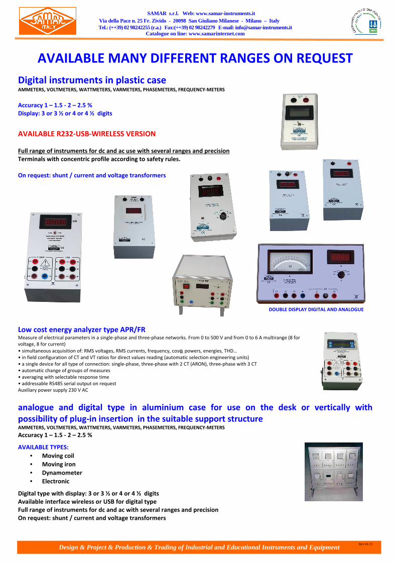
Design & Project & Production & Trading of Industrial and Educational Instruments and Equipment
SAMAR s.r.l. Web: www.samar-instruments.it Via della Pace n. 25 Fr. Zivido - 20098 San Giuliano Milanese - Milano – Italy Tel.: (++39) 02 98242255 (r.a.) Fax:(++39) 02 98242279 E-mail: [email protected]
Catalogue on line: www.samarinternet.com
Rev 04.15
AVAILABLE MANY DIFFERENT RANGES ON REQUEST
Digital instruments in plastic case AMMETERS, VOLTMETERS, WATTMETERS, VARMETERS, PHASEMETERS, FREQUENCY-METERS
Accuracy 1 – 1.5 - 2 – 2.5 %
Display: 3 or 3 ½ or 4 or 4 ½ digits
AVAILABLE R232-USB-WIRELESS VERSION
Full range of instruments for dc and ac use with several ranges and precision
Terminals with concentric profile according to safety rules.
On request: shunt / current and voltage transformers
Low cost energy analyzer type APR/FR Measure of electrical parameters in a single-phase and three-phase networks. From 0 to 500 V and from 0 to 6 A multirange (8 for
voltage, 8 for current)
• simultaneous acquisition of: RMS voltages, RMS currents, frequency, cosφ, powers, energies, THD…
• in field configuration of CT and VT ratios for direct values reading (automatic selection engineering units)
• a single device for all type of connection: single-phase, three-phase with 2 CT (ARON), three-phase with 3 CT
• automatic change of groups of measures
• averaging with selectable response time
• addressable RS485 serial output on request
Auxiliary power supply 230 V AC
analogue and digital type in aluminium case for use on the desk or vertically with
possibility of plug-in insertion in the suitable support structure AMMETERS, VOLTMETERS, WATTMETERS, VARMETERS, PHASEMETERS, FREQUENCY-METERS
Accuracy 1 – 1.5 - 2 – 2.5 %
AVAILABLE TYPES:
• Moving coil
• Moving iron
• Dynamometer
• Electronic
Digital type with display: 3 or 3 ½ or 4 or 4 ½ digits
Available interface wireless or USB for digital type
Full range of instruments for dc and ac with several ranges and precision
On request: shunt / current and voltage transformers
DOUBLE DISPLAY DIGITAL AND ANALOGUE