Embed Size (px)
Citation preview
ELECTRICAL MACHINES - II
COURSEFILE
Coursefile contents:
1. Cover Page
2. Syllabus copy
3. Vision of the department
4. Mission of the department
5. PEOs and POs
6. Course objectives and outcomes
7. Brief note on the importance of the course and how it fits in to the curriculum
8. Prerequisites
9. Instructional Learning Outcomes
10. Course mapping with PEOs and POs
11. Class Time Table
12. Individual Time Table
13. Lecture schedule with methodology being used/adopted
14. Detailed notes
15. Additional/missing topics
16. University previous Question papers
17. Question Bank
18. Assignment topics
19. Unit wise questions
20. Tutorial problems
21. Known gaps
22. Discussion topics
23. References, Journals, websites and E-links
24. Quality measurement Sheets
a. course and survey
b. Teaching evaluation
25. Student List
26. GroupWise Student List for discussion topics
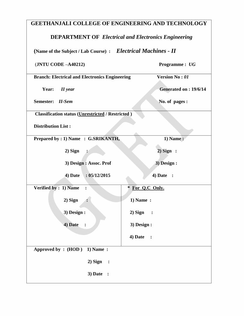
GEETHANJALI COLLEGE OF ENGINEERING AND TECHNOLOGY
DEPARTMENT OF Electrical and Electronics Engineering
(Name of the Subject / Lab Course) : Electrical Machines - II
(JNTU CODE –A40212) Programme : UG
Branch: Electrical and Electronics Engineering Version No : 01
Year: II year Generated on : 19/6/14
Semester: II-Sem No. of pages :
Classification status (Unrestricted / Restricted )
Distribution List :
Prepared by : 1) Name : G.SRIKANTH, 1) Name :
2) Sign : 2) Sign :
3) Design : Assoc. Prof 3) Design :
4) Date : 05/12/2015 4) Date :
Verified by : 1) Name :
2) Sign :
3) Design :
4) Date :
* For Q.C Only.
1) Name :
2) Sign :
3) Design :
4) Date :
Approved by : (HOD ) 1) Name :
2) Sign :
3) Date :
2. University Syallabus
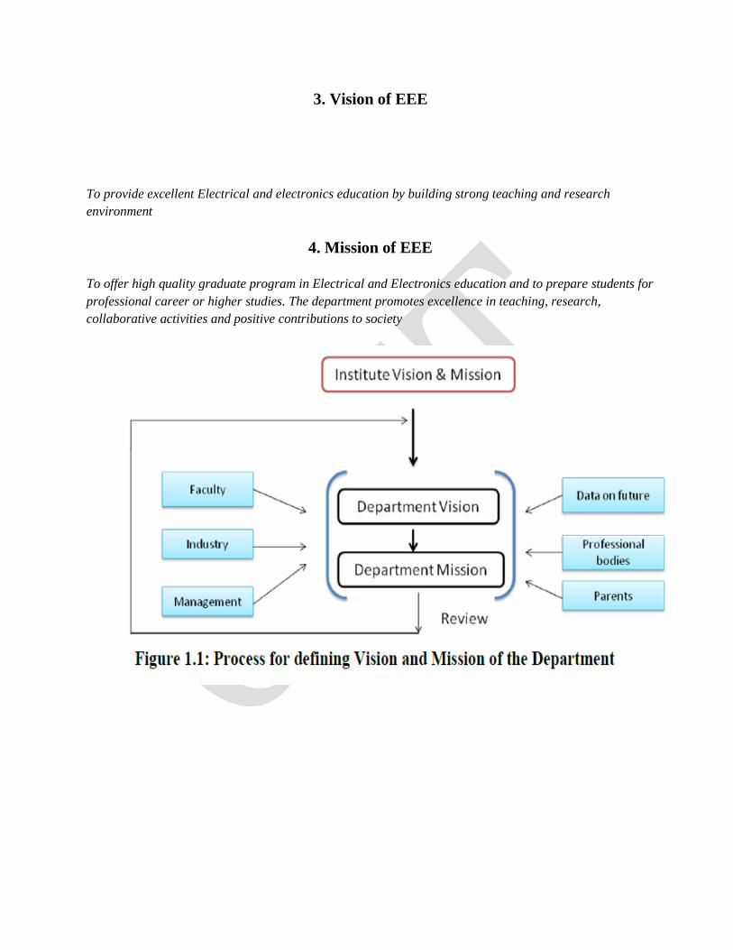
3. Vision of EEE
To provide excellent Electrical and electronics education by building strong teaching and research
environment
4. Mission of EEE
To offer high quality graduate program in Electrical and Electronics education and to prepare students for
professional career or higher studies. The department promotes excellence in teaching, research,
collaborative activities and positive contributions to society
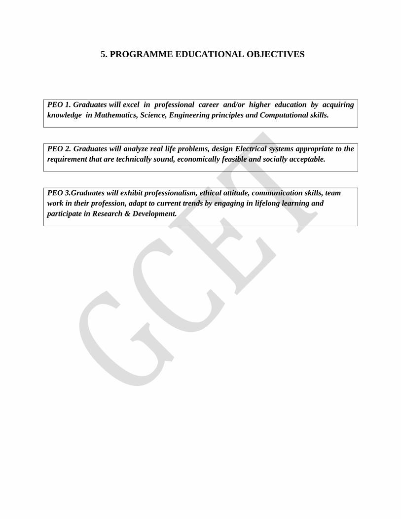
5. PROGRAMME EDUCATIONAL OBJECTIVES
PEO 1. Graduates will excel in professional career and/or higher education by acquiring
knowledge in Mathematics, Science, Engineering principles and Computational skills.
PEO 2. Graduates will analyze real life problems, design Electrical systems appropriate to the
requirement that are technically sound, economically feasible and socially acceptable.
PEO 3.Graduates will exhibit professionalism, ethical attitude, communication skills, team
work in their profession, adapt to current trends by engaging in lifelong learning and
participate in Research & Development.
PROGRAMME OUTCOMES
The Programme Outcomes of UG in Electrical and Electronics Engineering are as follows
PO 1. An ability to apply the knowledge of Mathematics, Science and
Engineering in Electrical and Electronics Engineering.
PO 2. An ability to design and conduct experiments pertaining to Electrical
and Electronics Engineering.
PO 3. An ability to function in multidisciplinary teams
PO 4. An ability to simulate and determine the parameters such as nominal
voltage current, power and associated attributes.
PO 5. An ability to identify, formulate and solve problems in the areas of
Electrical and Electronics Engineering.
PO 6. An ability to use appropriate network theorems to solve electrical
engineering problems.
PO 7. An ability to communicate effectively.
PO 8. An ability to visualize the impact of electrical engineering solutions in
global, economic and societal context.
PO 9. Recognition of the need and an ability to engage in life-long learning.
PO 10 An ability to understand contemporary issues related to alternate
energy sources.
PO 11 An ability to use the techniques, skills and modern engineering tools
necessary for Electrical Engineering Practice.
PO 12 An ability to simulate and determine the parameters like voltage profile
and current ratings of transmission lines in Power Systems.
PO 13 An ability to understand and determine the performance of electrical
machines namely speed, torque, efficiency etc.
PO 14 An ability to apply electrical engineering and management principles to
Power Projects.
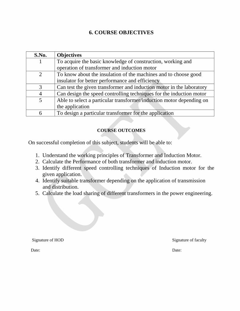
6. COURSE OBJECTIVES
S.No. Objectives
1 To acquire the basic knowledge of construction, working and
operation of transformer and induction motor
2 To know about the insulation of the machines and to choose good
insulator for better performance and efficiency
3 Can test the given transformer and induction motor in the laboratory
4 Can design the speed controlling techniques for the induction motor
5 Able to select a particular transformer/induction motor depending on
the application
6 To design a particular transformer for the application
COURSE OUTCOMES
On successful completion of this subject, students will be able to:
1. Understand the working principles of Transformer and Induction Motor.
2. Calculate the Performance of both transformer and induction motor.
3. Identify different speed controlling techniques of Induction motor for the
given application.
4. Identify suitable transformer depending on the application of transmission
and distribution.
5. Calculate the load sharing of different transformers in the power engineering.
Signature of HOD Signature of faculty
Date: Date:

7. Brief notes on the importance of the course and how it fit
into the curriculum
This is the fundamental course for the Electrical Engineering program. Also an extension to the previous
semester subject, Electrical Machines –I. It introduces the basic working principle and operation of
different types of transformers. It also provides the basic information of losses existing in the operation and
construction of transformers. It also gives their performance when connected in the power circuits.
It also gives the invention of Induction motors and their analogy with transformer construction and
operation. As the induction motor is one of the important load used in all applications it is very much
necessary to know about the construction, types, losses and working of different types of induction
motors. It also tells us the different methods of finding the efficiency of induction motor. Also tells us
different speed controlling techniques available for induction motors.
Finally this subject gives the information of two important electrical utilities in the power transmission,
distribution and utilization.
8. Prerequisites The fundamental knowledge of Engineering Physics, Mathematics .
The fundamental knowledge of Electromagnetic field theory, fundamental of machine operation
Information about different magnetic materials, insulation, etc.
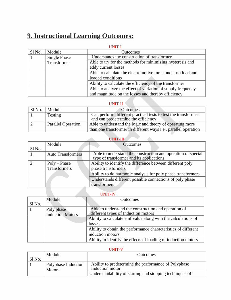
9. Instructional Learning Outcomes:
UNIT-I
Sl No. Module Outcomes
1 Single Phase
Transformer
Understands the construction of transformer Able to try for the methods for minimizing hysteresis and
eddy current losses
Able to calculate the electromotive force under no load and
loaded conditions
Ability to calculate the efficiency of the transformer
Able to analyze the effect of variation of supply frequency
and magnitude on the losses and thereby efficiency
UNIT-II
Sl No. Module Outcomes
1 Testing Can perform different practical tests to test the transformer and can predetermine the efficiency
2 Parallel Operation Able to understand the logic and theory of operating more
than one transformer in different ways i.e., parallel operation
UNIT-III
Sl No. Module Outcomes
1 Auto Transformers Able to understand the construction and operation of special type of transformer and its applications
2 Poly – Phase
Transformers
Ability to identify the difference between different poly
phase transformers
Ability to do harmonic analysis for poly phase transformers
Understands different possible connections of poly phase
transformers
UNIT-IV
Sl No. Module Outcomes
1 Poly phase
Induction Motors
Able to understand the construction and operation of different types of Induction motors
Ability to calculate emf value along with the calculations of
losses
Ability to obtain the performance characteristics of different
induction motors
Ability to identify the effects of loading of induction motors
UNIT-V
Sl No. Module Outcomes
1 Polyphase Induction
Motors
Ability to predetermine the performance of Polyphase Induction motor
Understandability of starting and stopping techniques of
Induction motor
Ability to control the speed of Induction motor
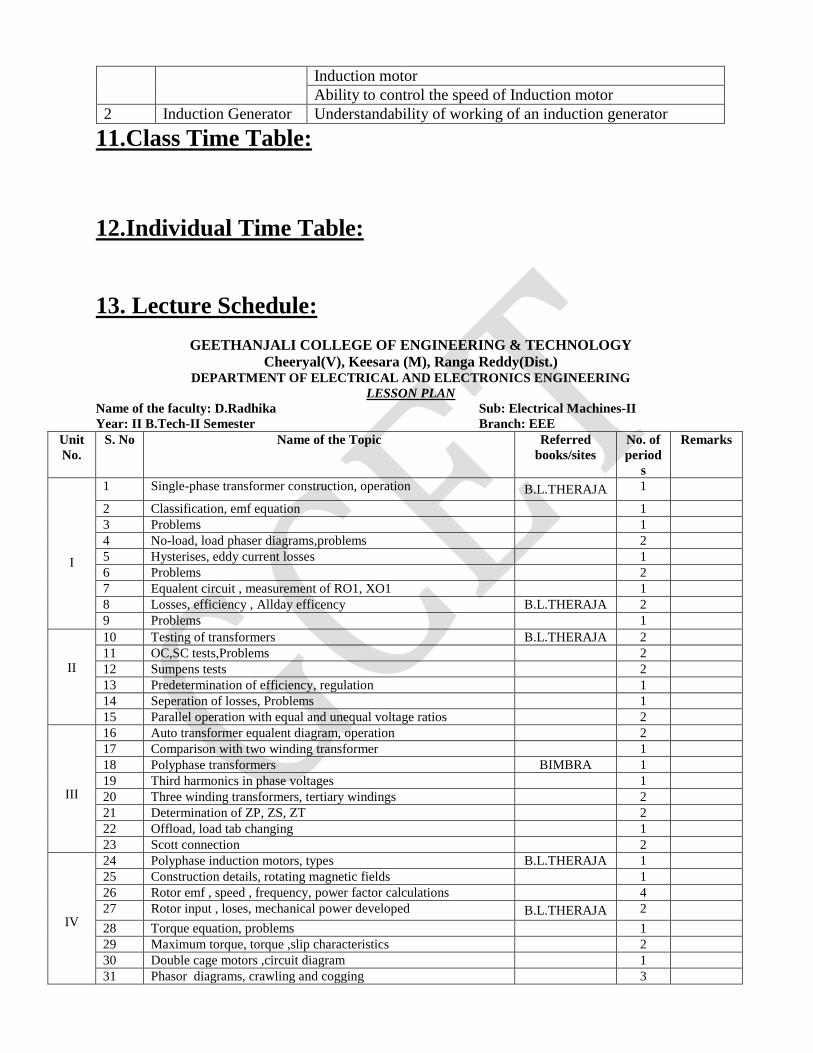
2 Induction Generator Understandability of working of an induction generator
11.Class Time Table:
12.Individual Time Table:
13. Lecture Schedule:
GEETHANJALI COLLEGE OF ENGINEERING & TECHNOLOGY
Cheeryal(V), Keesara (M), Ranga Reddy(Dist.) DEPARTMENT OF ELECTRICAL AND ELECTRONICS ENGINEERING
LESSON PLAN
Name of the faculty: D.Radhika Sub: Electrical Machines-II
Year: II B.Tech-II Semester Branch: EEE
Unit
No.
S. No Name of the Topic Referred
books/sites
No. of
period
s
Remarks
I
1 Single-phase transformer construction, operation B.L.THERAJA 1
2 Classification, emf equation 1
3 Problems 1
4 No-load, load phaser diagrams,problems 2
5 Hysterises, eddy current losses 1
6 Problems 2
7 Equalent circuit , measurement of RO1, XO1 1
8 Losses, efficiency , Allday efficency B.L.THERAJA 2
9 Problems 1
II
10 Testing of transformers B.L.THERAJA 2
11 OC,SC tests,Problems 2
12 Sumpens tests 2
13 Predetermination of efficiency, regulation 1
14 Seperation of losses, Problems 1
15 Parallel operation with equal and unequal voltage ratios 2
III
16 Auto transformer equalent diagram, operation 2
17 Comparison with two winding transformer 1
18 Polyphase transformers BIMBRA 1
19 Third harmonics in phase voltages 1
20 Three winding transformers, tertiary windings 2
21 Determination of ZP, ZS, ZT 2
22 Offload, load tab changing 1
23 Scott connection 2
IV
24 Polyphase induction motors, types B.L.THERAJA 1
25 Construction details, rotating magnetic fields 1
26 Rotor emf , speed , frequency, power factor calculations 4
27 Rotor input , loses, mechanical power developed B.L.THERAJA 2
28 Torque equation, problems 1
29 Maximum torque, torque ,slip characteristics 2
30 Double cage motors ,circuit diagram 1
31 Phasor diagrams, crawling and cogging 3
V
32 No load & blocked tests, circle diagram BIMBRA 3
33 Predetermination of performance 1
34 Methods of starting 2
35 Merits and Demerits 1
36 Current & torque calculations ,problems 3
37 Speed control methods BIMBRA 2
38 Cascade connection 1
39 Injection of an emf into rotor 2
40 Induction generator 2
41 Principle of Operation 2
Total Classes Required 68
Head of the Dept. Signature of the Faculty
14. Detailed Notes:
TRANSFORMERS A transformer is a device that transfers electrical energy from one circuit to another through
inductively coupled conductors—the transformer's coils. A varying current in the first or primary
winding creates a varying magnetic flux in the transformer's core and thus a varying magnetic
field through the secondary winding. This varying magnetic field induces a varying electromotive
force (EMF), or "voltage", in the secondary winding. This effect is called inductive coupling.
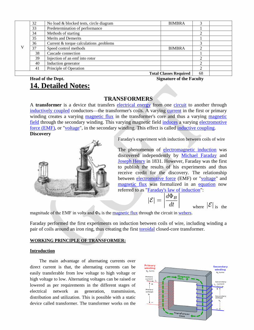
Discovery Faraday's experiment with induction between coils of wire
The phenomenon of electromagnetic induction was
discovered independently by Michael Faraday and
Joseph Henry in 1831. However, Faraday was the first
to publish the results of his experiments and thus
receive credit for the discovery. The relationship
between electromotive force (EMF) or "voltage" and
magnetic flux was formalized in an equation now
referred to as "Faraday's law of induction":
where is the
magnitude of the EMF in volts and ΦB is the magnetic flux through the circuit in webers.
Faraday performed the first experiments on induction between coils of wire, including winding a
pair of coils around an iron ring, thus creating the first toroidal closed-core transformer.
WORKING PRINCIPLE OF TRANSFORMER:
Introduction
The main advantage of alternating currents over
direct current is that, the alternating currents can be
easily transferable from low voltage to high voltage or
high voltage to low. Alternating voltages can be raised or
lowered as per requirements in the different stages of
electrical network as generation, transmission,
distribution and utilization. This is possible with a static
device called transformer. The transformer works on the
principle of mutual induction. It transfer an electric energy from one circuit to other when there is no
electrical connection between the tow circuits. Thus we can define transformer as below :
Key point : The transformer is a static piece of apparatus by means of which an electrical power is
transformed from one alternating current circuit to another with the desired change in voltage and current,
without any change in the frequency.
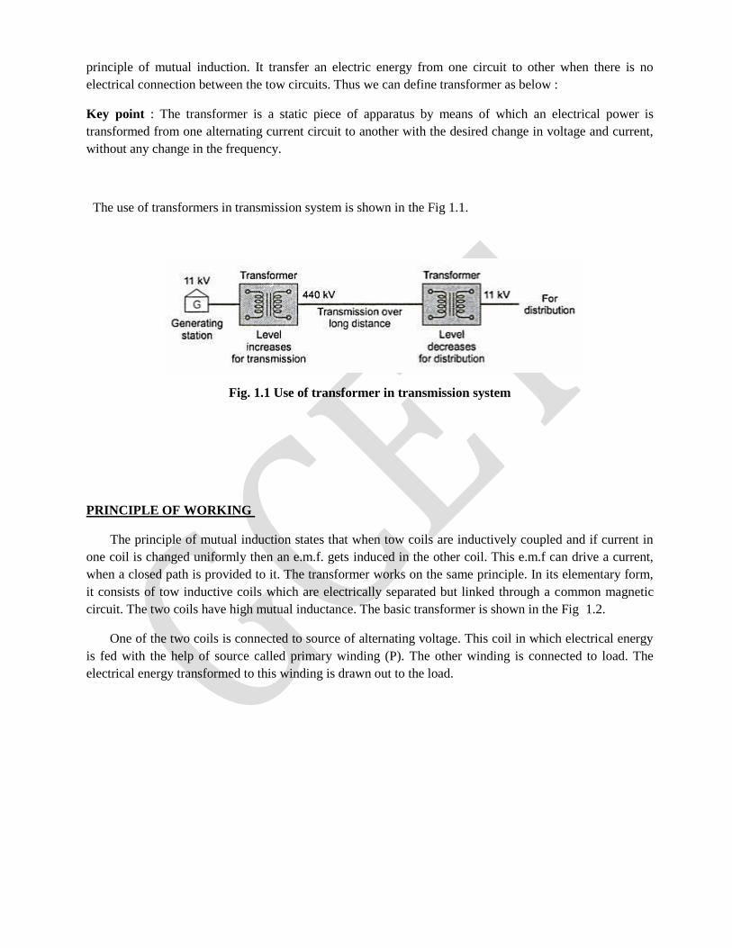
The use of transformers in transmission system is shown in the Fig 1.1.
Fig. 1.1 Use of transformer in transmission system
PRINCIPLE OF WORKING
The principle of mutual induction states that when tow coils are inductively coupled and if current in
one coil is changed uniformly then an e.m.f. gets induced in the other coil. This e.m.f can drive a current,
when a closed path is provided to it. The transformer works on the same principle. In its elementary form,
it consists of tow inductive coils which are electrically separated but linked through a common magnetic
circuit. The two coils have high mutual inductance. The basic transformer is shown in the Fig 1.2.
One of the two coils is connected to source of alternating voltage. This coil in which electrical energy
is fed with the help of source called primary winding (P). The other winding is connected to load. The
electrical energy transformed to this winding is drawn out to the load.
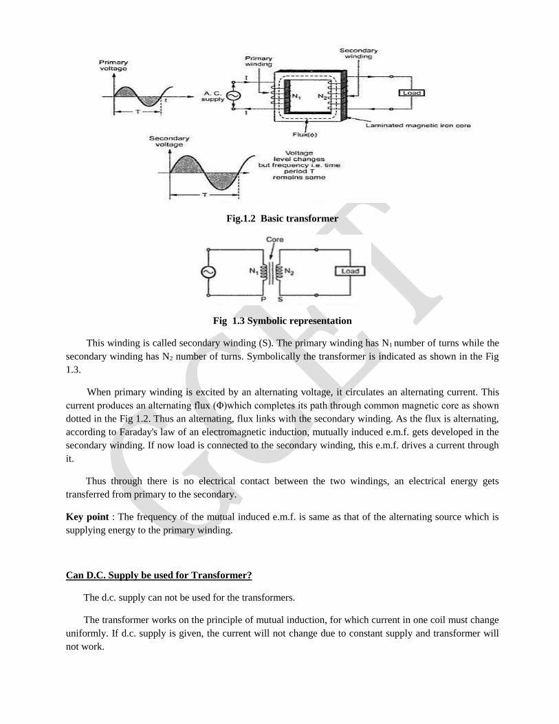
Fig.1.2 Basic transformer
Fig 1.3 Symbolic representation
This winding is called secondary winding (S). The primary winding has N1 number of turns while the
secondary winding has N2 number of turns. Symbolically the transformer is indicated as shown in the Fig
1.3.
When primary winding is excited by an alternating voltage, it circulates an alternating current. This
current produces an alternating flux (Φ)which completes its path through common magnetic core as shown
dotted in the Fig 1.2. Thus an alternating, flux links with the secondary winding. As the flux is alternating,
according to Faraday's law of an electromagnetic induction, mutually induced e.m.f. gets developed in the
secondary winding. If now load is connected to the secondary winding, this e.m.f. drives a current through
it.
Thus through there is no electrical contact between the two windings, an electrical energy gets
transferred from primary to the secondary.
Key point : The frequency of the mutual induced e.m.f. is same as that of the alternating source which is
supplying energy to the primary winding.
Can D.C. Supply be used for Transformer?
The d.c. supply can not be used for the transformers.
The transformer works on the principle of mutual induction, for which current in one coil must change
uniformly. If d.c. supply is given, the current will not change due to constant supply and transformer will
not work.
Practically winding resistance is very small. For d.c., the inductive reactance XL is zero as d.c. has no
frequency. So total impedance of winding is very low for d.c. Thus winding will draw very high current if
d.c. supply is given to it. This may cause the burning of windings due to extra heat generated and may
cause permanent damage to the transformer.
There can be saturation of the core due to which transformer draws very large current from the supply
when connected to d.c.
Thus d.c. supply should not be connected to the transformers.
CONSTRUCTION OF TRANSFORMER: There are two basic parts of a transformer i) Magnetic Core ii) Winding or Coils.
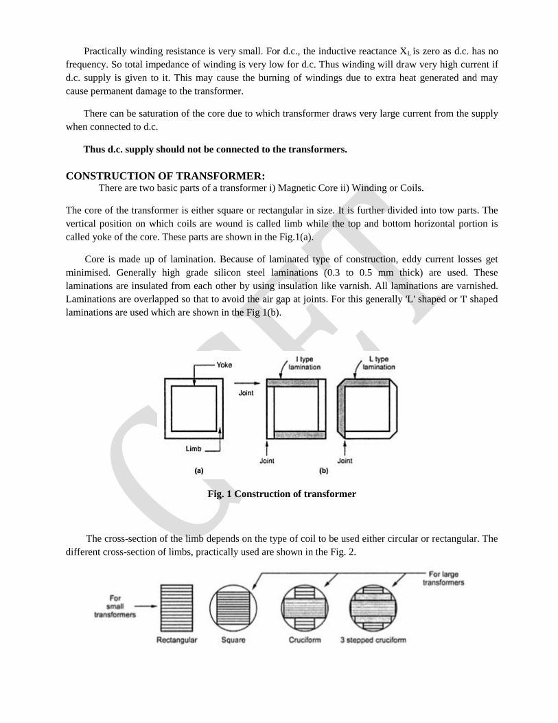
The core of the transformer is either square or rectangular in size. It is further divided into tow parts. The
vertical position on which coils are wound is called limb while the top and bottom horizontal portion is
called yoke of the core. These parts are shown in the Fig.1(a).
Core is made up of lamination. Because of laminated type of construction, eddy current losses get
minimised. Generally high grade silicon steel laminations (0.3 to 0.5 mm thick) are used. These
laminations are insulated from each other by using insulation like varnish. All laminations are varnished.
Laminations are overlapped so that to avoid the air gap at joints. For this generally 'L' shaped or 'I' shaped
laminations are used which are shown in the Fig 1(b).
Fig. 1 Construction of transformer
The cross-section of the limb depends on the type of coil to be used either circular or rectangular. The
different cross-section of limbs, practically used are shown in the Fig. 2.
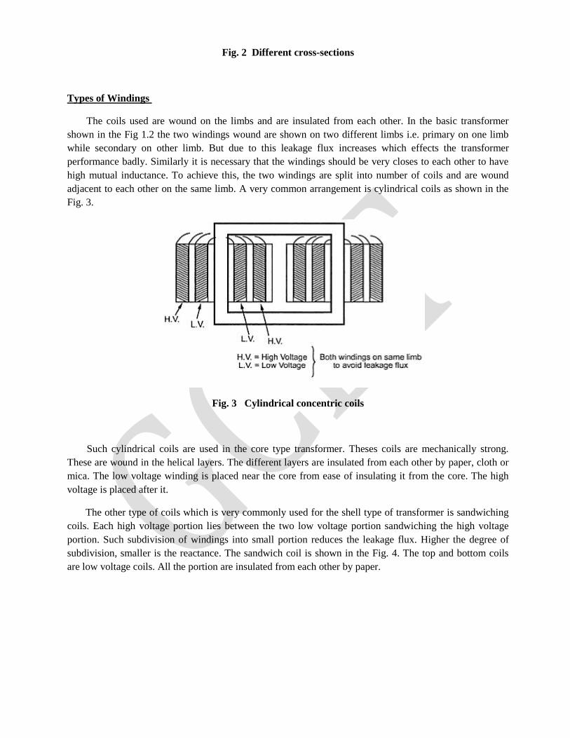
Fig. 2 Different cross-sections
Types of Windings
The coils used are wound on the limbs and are insulated from each other. In the basic transformer
shown in the Fig 1.2 the two windings wound are shown on two different limbs i.e. primary on one limb
while secondary on other limb. But due to this leakage flux increases which effects the transformer
performance badly. Similarly it is necessary that the windings should be very closes to each other to have
high mutual inductance. To achieve this, the two windings are split into number of coils and are wound
adjacent to each other on the same limb. A very common arrangement is cylindrical coils as shown in the
Fig. 3.
Fig. 3 Cylindrical concentric coils
Such cylindrical coils are used in the core type transformer. Theses coils are mechanically strong.
These are wound in the helical layers. The different layers are insulated from each other by paper, cloth or
mica. The low voltage winding is placed near the core from ease of insulating it from the core. The high
voltage is placed after it.
The other type of coils which is very commonly used for the shell type of transformer is sandwiching
coils. Each high voltage portion lies between the two low voltage portion sandwiching the high voltage
portion. Such subdivision of windings into small portion reduces the leakage flux. Higher the degree of
subdivision, smaller is the reactance. The sandwich coil is shown in the Fig. 4. The top and bottom coils
are low voltage coils. All the portion are insulated from each other by paper.

Fig. 4 Sandwich coils
The various types of depending on the construction of core used for the single phase transformers are,
1. Core type 2. shell type and 3. Berry type
1. Core Type Transformer
It has a single magnetic circuit. The core rectangular having two limbs. The winding encircles the core.
The coils used are of cylindrical type. As mentioned earlier, the coils are wound in helical layers with
different layers insulated from each other by paper or mica. Both the coils are placed on both the limbs.
The low voltage coil is placed inside near the core while high voltage coil surrounds the low voltage coil.
Core is made up of large number of thin laminations.
As The windings are uniformly distributed over the two limbs, the natural cooling is more effective.
The coils can be easily removed by removing the laminations of the top yoke, for maintenance.
The Fig. 1(a) shows the schematic representation of the core type transformer while the Fig 1(b) shows
the view of actual construction of the core type transformer.
Fig. 1 Core type transformer
2. Shell Type Transformer
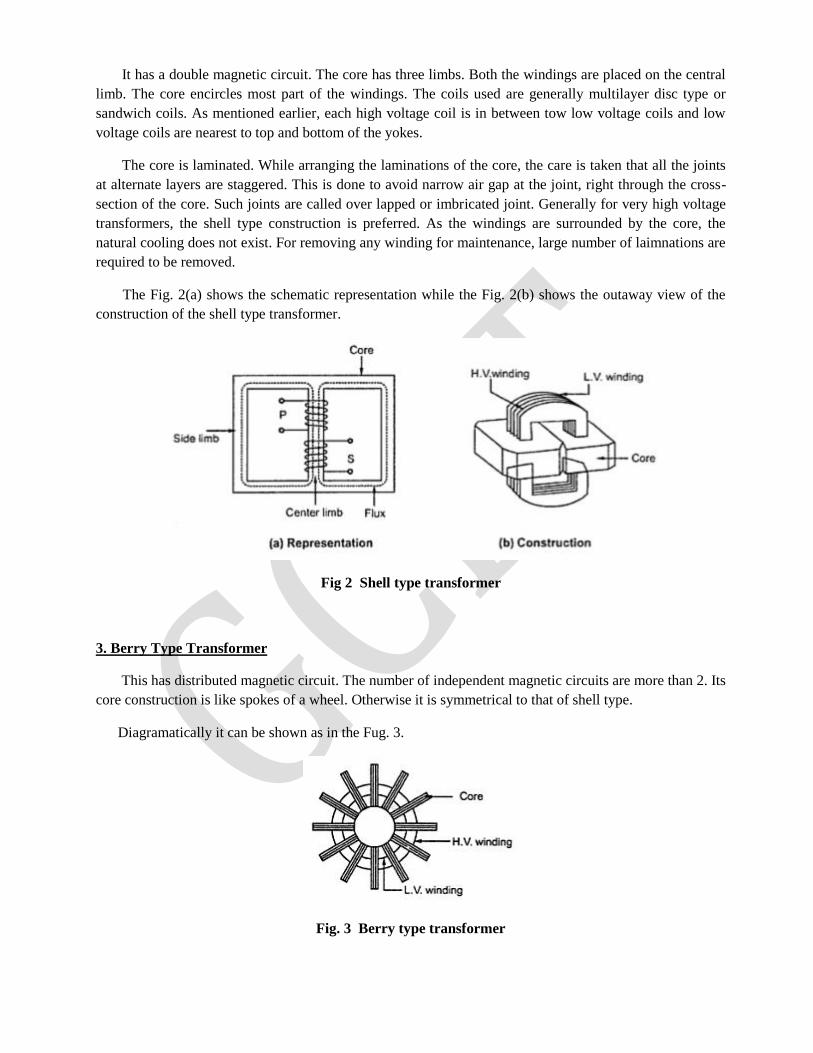
It has a double magnetic circuit. The core has three limbs. Both the windings are placed on the central
limb. The core encircles most part of the windings. The coils used are generally multilayer disc type or
sandwich coils. As mentioned earlier, each high voltage coil is in between tow low voltage coils and low
voltage coils are nearest to top and bottom of the yokes.
The core is laminated. While arranging the laminations of the core, the care is taken that all the joints
at alternate layers are staggered. This is done to avoid narrow air gap at the joint, right through the cross-
section of the core. Such joints are called over lapped or imbricated joint. Generally for very high voltage
transformers, the shell type construction is preferred. As the windings are surrounded by the core, the
natural cooling does not exist. For removing any winding for maintenance, large number of laimnations are
required to be removed.
The Fig. 2(a) shows the schematic representation while the Fig. 2(b) shows the outaway view of the
construction of the shell type transformer.
Fig 2 Shell type transformer
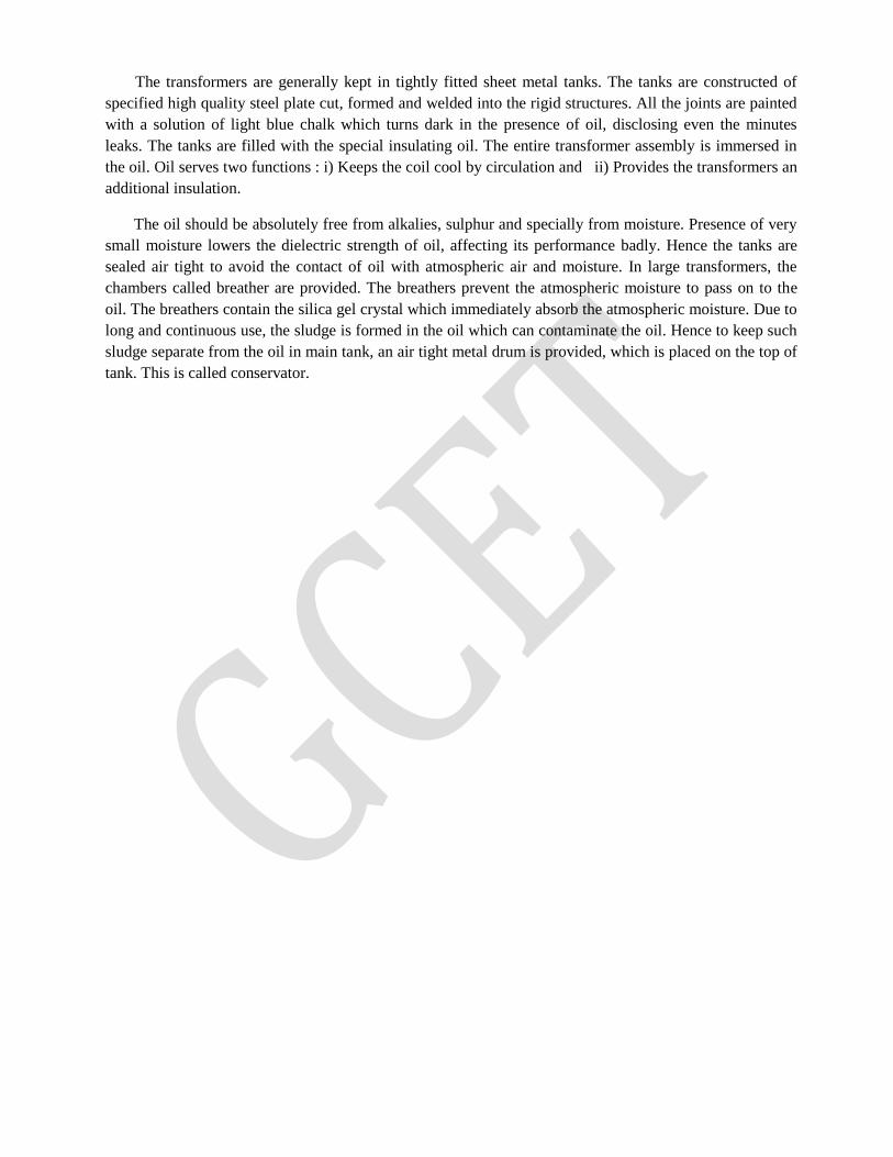
3. Berry Type Transformer
This has distributed magnetic circuit. The number of independent magnetic circuits are more than 2. Its
core construction is like spokes of a wheel. Otherwise it is symmetrical to that of shell type.
Diagramatically it can be shown as in the Fug. 3.
Fig. 3 Berry type transformer
The transformers are generally kept in tightly fitted sheet metal tanks. The tanks are constructed of
specified high quality steel plate cut, formed and welded into the rigid structures. All the joints are painted
with a solution of light blue chalk which turns dark in the presence of oil, disclosing even the minutes
leaks. The tanks are filled with the special insulating oil. The entire transformer assembly is immersed in
the oil. Oil serves two functions : i) Keeps the coil cool by circulation and ii) Provides the transformers an
additional insulation.
The oil should be absolutely free from alkalies, sulphur and specially from moisture. Presence of very
small moisture lowers the dielectric strength of oil, affecting its performance badly. Hence the tanks are
sealed air tight to avoid the contact of oil with atmospheric air and moisture. In large transformers, the
chambers called breather are provided. The breathers prevent the atmospheric moisture to pass on to the
oil. The breathers contain the silica gel crystal which immediately absorb the atmospheric moisture. Due to
long and continuous use, the sludge is formed in the oil which can contaminate the oil. Hence to keep such
sludge separate from the oil in main tank, an air tight metal drum is provided, which is placed on the top of
tank. This is called conservator.
Comparison of Core and Shell Type Transformers
E.M.F EQUATION OF TRANSFORMER: When the primary winding is excited by an alternating voltage V1, it circulates alternating current,
producing an alternating flux Φ. The primary winding has N1 number of turns. The alternating flux Φ
linking with the primary winding itself induces an e.m.f in it denoted as E1. The flux links with secondary
winding through the common magnetic core. It produces induced e.m.f. E2 in the secondary winding. This
is mutually induced e.m.f. Let us derive the equations for E1 and E2.
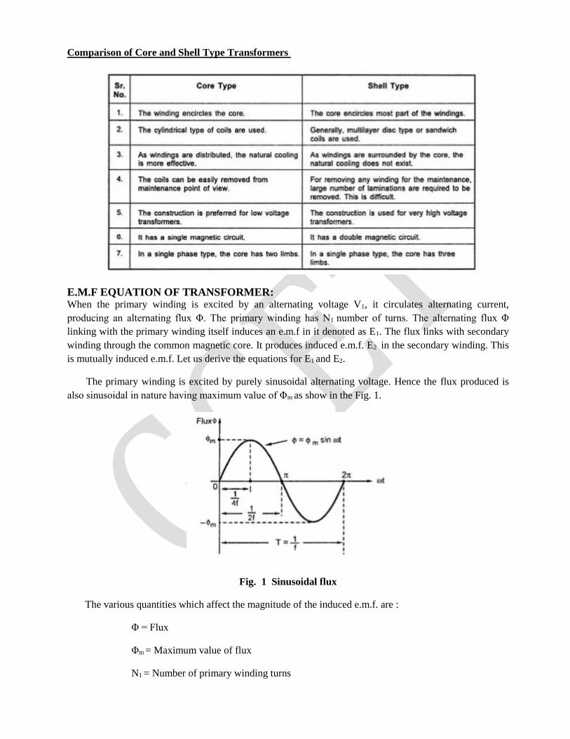
The primary winding is excited by purely sinusoidal alternating voltage. Hence the flux produced is
also sinusoidal in nature having maximum value of Φm as show in the Fig. 1.
Fig. 1 Sinusoidal flux
The various quantities which affect the magnitude of the induced e.m.f. are :
Φ = Flux
Φm = Maximum value of flux
N1 = Number of primary winding turns
N2 = Number of secondary winding turns
f = Frequency of the supply voltage
E1 = R.M.S. value of the primary induced e.m.f.
E2 = R.M.S. value of the secondary induced e.m.f.
From Faraday's law of electromagnetic induction the voltage e.m.f. induced in each turn is
proportional to the average rate of change of flux.
... average e.m.f. per turn = average rate of change of flux
... average e.m.f. per turn = dΦ/dt
Now dΦ/dt = Change in flux/Time required for change in flux
Consider the 1/4 th cycle of the flux as shown in the Fig.1. Complete cycle gets completed in 1/f
seconds. In 1/4 th time period, the change in flux is from 0 to Φm.
... dΦ/dt = (Φm - 0)/(1/4f) as dt for 1/4 th time period is 1/4f seconds
= 4 f Φm Wb/sec
... Average e.m.f. per turn = 4 f Φm volts
As is sinusoidal, the induced e.m.f. in each turn of both the windings is also sinusoidal in nature. For
sinusoidal quantity,
From factor = R.M.S. value/Average value = 1.11
... R.M.S. value of induced e.m.f. per turn
= 1.11 x 4 f Φm = 4.44 f Φm
There are number of primary turns hence the R.M.S value of induced e.m.f. of primary denoted as is
E1,
E1 = N1 x 4.44 f Φm volts
While as there are number of secondary turns the R.M.S values of induced e.m.f. of secondary denoted
is E2 is,
E2 = N2 x 4.44 f Φm volts
The expression of E1 and E2 are called e.m.f. equation of a transformer.
Thus e.m.f. equations are,
E1 = 4.44 f Φm N1 volts ............(1)
E2 = 4.44 f Φm N2 volts .............(2)
Transformation Ratio(k)
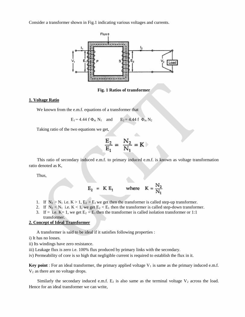
Consider a transformer shown in Fig.1 indicating various voltages and currents.
Fig. 1 Ratios of transformer
1. Voltage Ratio
We known from the e.m.f. equations of a transformer that
E1 = 4.44 f Φm N1 and E2 = 4.44 f Φm N2
Taking ratio of the two equations we get,
This ratio of secondary induced e.m.f. to primary induced e.m.f. is known as voltage transformation
ratio denoted as K,
Thus,
1. If N2 > N1 i.e. K > 1, E2 > E1 we get then the transformer is called step-up transformer.
2. If N2 < N1 i.e. K < 1, we get E2 < E1 then the transformer is called step-down transformer.
3. If = i.e. K= 1, we get E2 = E1 then the transformer is called isolation transformer or 1:1
transformer.
2. Concept of Ideal Transformer
A transformer is said to be ideal if it satisfies following properties :
i) It has no losses.
ii) Its windings have zero resistance.
iii) Leakage flux is zero i.e. 100% flux produced by primary links with the secondary.
iv) Permeability of core is so high that negligible current is required to establish the flux in it.
Key point : For an ideal transformer, the primary applied voltage V1 is same as the primary induced e.m.f.
V2 as there are no voltage drops.
Similarly the secondary induced e.m.f. E2 is also same as the terminal voltage V2 across the load.
Hence for an ideal transformer we can write,
No transformer is ideal in practice but the value of E1 is almost equal to V1 for properly designed
transformer.
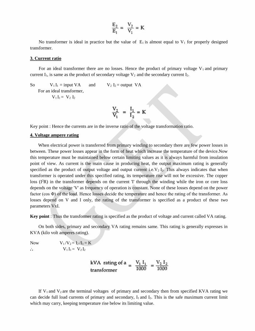
3. Current ratio
For an ideal transformer there are no losses. Hence the product of primary voltage V1 and primary
current I1, is same as the product of secondary voltage V2 and the secondary current I2.
So V1 I1 = input VA and V2 I2 = output VA
For an ideal transformer,
V1 I1 = V2 I2
Key point : Hence the currents are in the inverse ratio of the voltage transformation ratio.
4. Voltage ampere rating
When electrical power is transferred from primary winding to secondary there are few power losses in
between. These power losses appear in the form of heat which increase the temperature of the device.Now
this temperature must be maintained below certain limiting values as it is always harmful from insulation
point of view. As current is the main cause in producing heat, the output maximum rating is generally
specified as the product of output voltage and output current i.e.V2 I2. This always indicates that when
transformer is operated under this specified rating, its temperature rise will not be excessive. The copper
loss (I2R) in the transformer depends on the current 'I' through the winding while the iron or core loss
depends on the voltage 'V' as frequency of operation is constant. None of these losses depend on the power
factor (cos Φ) of the load. Hence losses decide the temperature and hence the rating of the transformer. As
losses depend on V and I only, the rating of the transformer is specified as a product of these two
parameters VxI.
Key point : Thus the transformer rating is specified as the product of voltage and current called VA rating.
On both sides, primary and secondary VA rating remains same. This rating is generally expresses in
KVA (kilo volt amperes rating).
Now V1 /V2 = I2 /I1 = K
... V1 I1 = V2 I2
If V1 and V2 are the terminal voltages of primary and secondary then from specified KVA rating we
can decide full load currents of primary and secondary, I1 and I2. This is the safe maximum current limit
which may carry, keeping temperature rise below its limiting value.
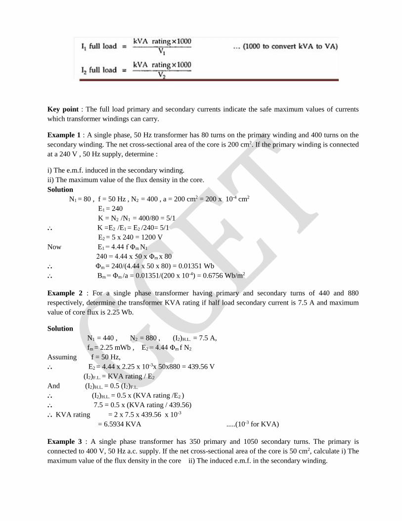
Key point : The full load primary and secondary currents indicate the safe maximum values of currents
which transformer windings can carry.
Example 1 : A single phase, 50 Hz transformer has 80 turns on the primary winding and 400 turns on the
secondary winding. The net cross-sectional area of the core is 200 cm2. If the primary winding is connected
at a 240 V , 50 Hz supply, determine :
i) The e.m.f. induced in the secondary winding.
ii) The maximum value of the flux density in the core.
Solution
N1 = 80 , f = 50 Hz , N2 = 400 , a = 200 cm2 = 200 x 10-4 cm2
E1 = 240
K = N2 /N1 = 400/80 = 5/1
... K =E2 /E1 = E2 /240= 5/1
E2 = 5 x 240 = 1200 V
Now E1 = 4.44 f Φm N1
240 = 4.44 x 50 x Φm x 80
... Φm = 240/(4.44 x 50 x 80) = 0.01351 Wb
... Bm = Φm /a = 0.01351/(200 x 10-4) = 0.6756 Wb/m2
Example 2 : For a single phase transformer having primary and secondary turns of 440 and 880
respectively, determine the transformer KVA rating if half load secondary current is 7.5 A and maximum
value of core flux is 2.25 Wb.
Solution
N1 = 440 , N2 = 880 , (I2)H.L. = 7.5 A,
fm = 2.25 mWb , E2 = 4.44 Φm f N2
Assuming f = 50 Hz,
... E2 = 4.44 x 2.25 x 10-3x 50x880 = 439.56 V
(I2)F.L. = KVA rating / E2
And (I2)H.L. = 0.5 (I2)F.L.
... (I2)H.L. = 0.5 x (KVA rating /E2 )
... 7.5 = 0.5 x (KVA rating / 439.56)
... KVA rating = 2 x 7.5 x 439.56 x 10-3
= 6.5934 KVA .....(10-3 for KVA)
Example 3 : A single phase transformer has 350 primary and 1050 secondary turns. The primary is
connected to 400 V, 50 Hz a.c. supply. If the net cross-sectional area of the core is 50 cm2, calculate i) The
maximum value of the flux density in the core ii) The induced e.m.f. in the secondary winding.
Solution
The given value are,
N1 = 350 turns, N2 = 1050 turns
V1 = 400 V , A = 50 cm2= 50 x 10-4 m2
The e.m.f. of the transformer is,
E1 = 4.44 f Φm N1
E1 = 4.44 Bm A f N1 as Φm = Bm A
Flux density Bm = E1 / (4.44 A f N1)
= 400 / (4.44 x 50 x 10-4 x50 x 350) assume E1 = V1
= 1.0296 Wb/m2
K = N2 /N1 = 1050/350 = 3
And K = E2 /E1 = 3
... E2 = 3 x E1 = 3 x 400 = 1200 V
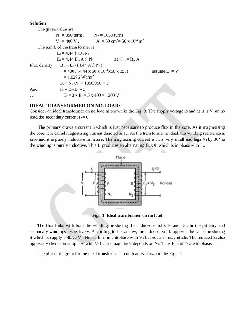
IDEAL TRANSFORMER ON NO-LOAD: Consider an ideal transformer on no load as shown in the Fig. 3. The supply voltage is and as it is V1 an no
load the secondary current I2 = 0.
The primary draws a current I1 which is just necessary to produce flux in the core. As it magnetising
the core, it is called magnetising current denoted as Im. As the transformer is ideal, the winding resistance is
zero and it is purely inductive in nature. The magnetising current is Im is very small and lags V1 by 30o as
the winding is purely inductive. This Im produces an alternating flux Φ which is in phase with Im.
Fig. 1 Ideal transformer on no load
The flux links with both the winding producing the induced e.m.f.s E1 and E2 , in the primary and
secondary windings respectively. According to Lenz's law, the induced e.m.f. opposes the cause producing
it which is supply voltage V1. Hence E1 is in antiphase with V1 but equal in magnitude. The induced E2 also
opposes V1 hence in antiphase with V1 but its magnitude depends on N2. Thus E1 and E2 are in phase.
The phasor diagram for the ideal transformer on no load is shown in the Fig. .2.
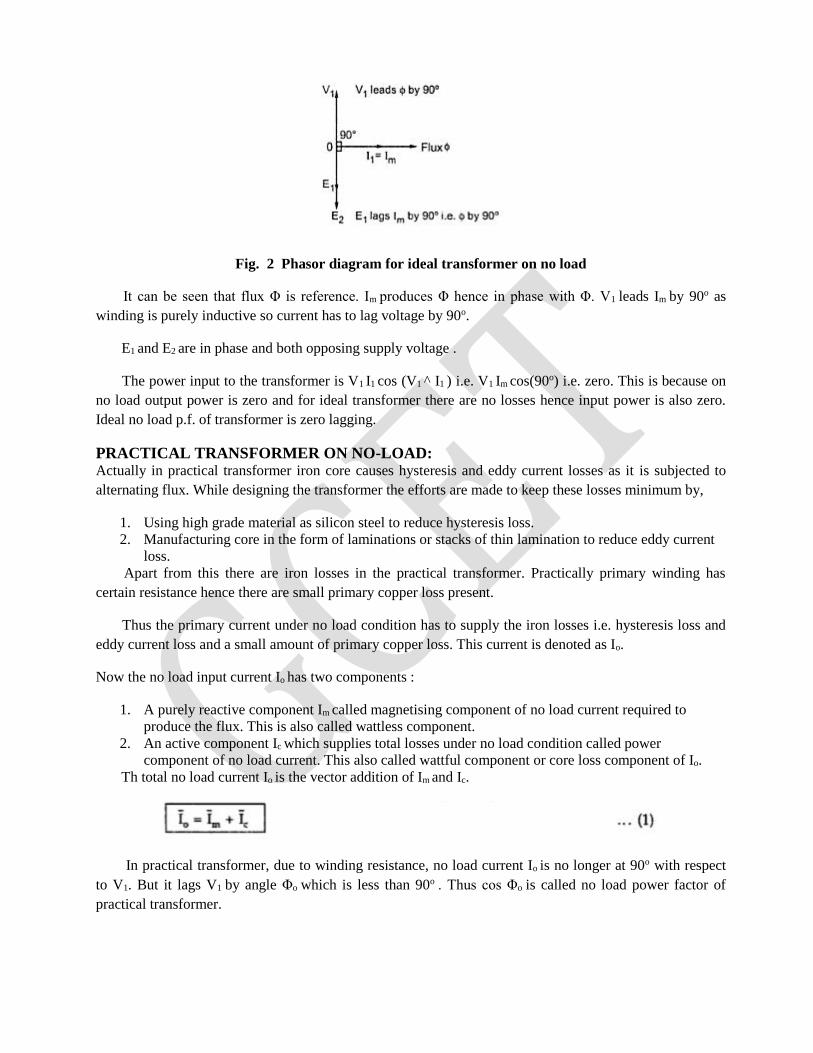
Fig. 2 Phasor diagram for ideal transformer on no load
It can be seen that flux Φ is reference. Im produces Φ hence in phase with Φ. V1 leads Im by 90o as
winding is purely inductive so current has to lag voltage by 90o.
E1 and E2 are in phase and both opposing supply voltage .
The power input to the transformer is V1 I1 cos (V1 ^ I1 ) i.e. V1 Im cos(90o) i.e. zero. This is because on
no load output power is zero and for ideal transformer there are no losses hence input power is also zero.
Ideal no load p.f. of transformer is zero lagging.
PRACTICAL TRANSFORMER ON NO-LOAD: Actually in practical transformer iron core causes hysteresis and eddy current losses as it is subjected to
alternating flux. While designing the transformer the efforts are made to keep these losses minimum by,
1. Using high grade material as silicon steel to reduce hysteresis loss.
2. Manufacturing core in the form of laminations or stacks of thin lamination to reduce eddy current
loss.
Apart from this there are iron losses in the practical transformer. Practically primary winding has
certain resistance hence there are small primary copper loss present.
Thus the primary current under no load condition has to supply the iron losses i.e. hysteresis loss and
eddy current loss and a small amount of primary copper loss. This current is denoted as Io.
Now the no load input current Io has two components :
1. A purely reactive component Im called magnetising component of no load current required to
produce the flux. This is also called wattless component.
2. An active component Ic which supplies total losses under no load condition called power
component of no load current. This also called wattful component or core loss component of Io.
Th total no load current Io is the vector addition of Im and Ic.
In practical transformer, due to winding resistance, no load current Io is no longer at 90o with respect
to V1. But it lags V1 by angle Φo which is less than 90o . Thus cos Φo is called no load power factor of
practical transformer.
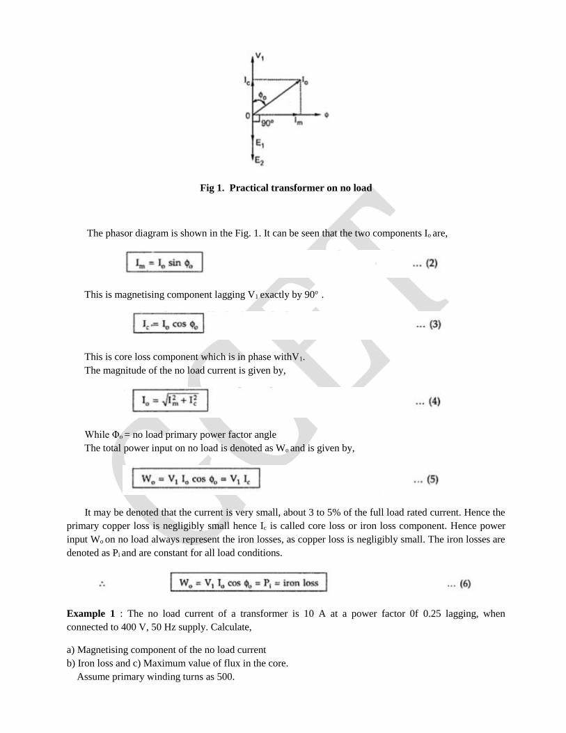
Fig 1. Practical transformer on no load
The phasor diagram is shown in the Fig. 1. It can be seen that the two components Io are,
This is magnetising component lagging V1 exactly by 90o .
This is core loss component which is in phase withV1.
The magnitude of the no load current is given by,
While Φo = no load primary power factor angle
The total power input on no load is denoted as Wo and is given by,
It may be denoted that the current is very small, about 3 to 5% of the full load rated current. Hence the
primary copper loss is negligibly small hence Ic is called core loss or iron loss component. Hence power
input Wo on no load always represent the iron losses, as copper loss is negligibly small. The iron losses are
denoted as Pi and are constant for all load conditions.
Example 1 : The no load current of a transformer is 10 A at a power factor 0f 0.25 lagging, when
connected to 400 V, 50 Hz supply. Calculate,
a) Magnetising component of the no load current
b) Iron loss and c) Maximum value of flux in the core.
Assume primary winding turns as 500.
Solution : The given value are, = 10 A, cos = 0.25, = 400 V and f = 50 Hz
a) Im = Io sin Φo = magnetising component
Φo = cos-1(0.25) = 75.522o
... Im = 10 x sin (75.522o ) = 9.6824 A
b) Pi = iron loss = power input on no load
= Wo = V1 Io cos Φo = 400 x 10 x 0.25
= 1000 W
c) On no load, E1 = V1 = 400 V and N1 = 500
Now E1 = 4.44 f Φm N1
... 400 = 4.44 x 50 x Φm x 500
... Φm = 3.6036 mWb
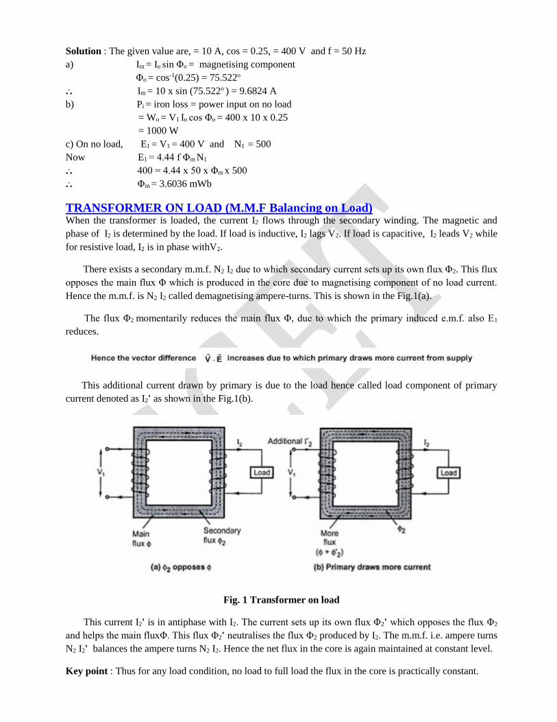
TRANSFORMER ON LOAD (M.M.F Balancing on Load) When the transformer is loaded, the current I2 flows through the secondary winding. The magnetic and
phase of I2 is determined by the load. If load is inductive, I2 lags V2. If load is capacitive, I2 leads V2 while
for resistive load, I2 is in phase withV2.
There exists a secondary m.m.f. N2 I2 due to which secondary current sets up its own flux Φ2. This flux
opposes the main flux Φ which is produced in the core due to magnetising component of no load current.
Hence the m.m.f. is N2 I2 called demagnetising ampere-turns. This is shown in the Fig.1(a).
The flux Φ2 momentarily reduces the main flux Φ, due to which the primary induced e.m.f. also E1
reduces.
This additional current drawn by primary is due to the load hence called load component of primary
current denoted as I2' as shown in the Fig.1(b).
Fig. 1 Transformer on load
This current I2' is in antiphase with I2. The current sets up its own flux Φ2' which opposes the flux Φ2
and helps the main fluxΦ. This flux Φ2' neutralises the flux Φ2 produced by I2. The m.m.f. i.e. ampere turns
N2 I2' balances the ampere turns N2 I2. Hence the net flux in the core is again maintained at constant level.
Key point : Thus for any load condition, no load to full load the flux in the core is practically constant.
The load component current I2' always neutralises the changes in the loads. Hence the transformer is
called constant flux machine.
As the ampere turns are balanced we can write,
N2 I2=N2 I2'
... I2' =(N2/N1) = K I2 ..................(1)
Thus when transformer is loaded, the primary current I1 has two components :
1. The no load current Io which lags V1 by angle Φo. It has two components Im and Ic.
2. The load component I2' which in antiphase with I2. And phase of I2 is decided by the load.
Hence primary current I1 is vector sum of Io and I2'.
... Ī1 = Īo + Ī2 ...............(2)
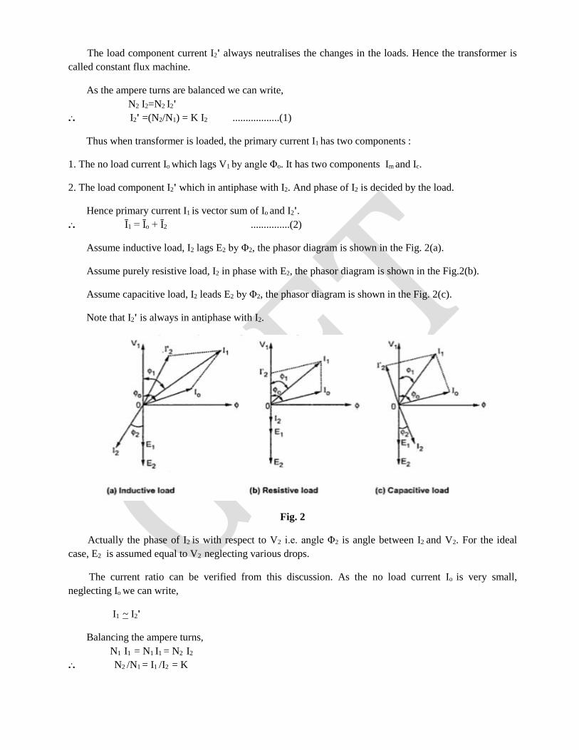
Assume inductive load, I2 lags E2 by Φ2, the phasor diagram is shown in the Fig. 2(a).
Assume purely resistive load, I2 in phase with E2, the phasor diagram is shown in the Fig.2(b).
Assume capacitive load, I2 leads E2 by Φ2, the phasor diagram is shown in the Fig. 2(c).
Note that I2' is always in antiphase with I2.
Fig. 2
Actually the phase of I2 is with respect to V2 i.e. angle Φ2 is angle between I2 and V2. For the ideal
case, E2 is assumed equal to V2 neglecting various drops.
The current ratio can be verified from this discussion. As the no load current Io is very small,
neglecting Io we can write,
I1 ~ I2'
Balancing the ampere turns,
N1 I1 = N1 I1 = N2 I2
... N2 /N1 = I1 /I2 = K
Under full load conditions when Io is very small compared to full load currents, the ratio of primary
and secondary current is constant.
Example : A 400/200 V transformer takes 1 A at a power factor of 0.4 on no load. If the secondary
supplies a load current of 50 A at 0.8 lagging power factor, calculate the primary current.
Solution : The given values are
Io = 1 A, cos Φo = 0.4, I2 = 50 A and cos Φ2 = .08
K = E2/E1 = 200/400 = 0.5
... I2' = K I2 = 0.5 x 50 = 25 A
The angle of I2' is to be decided from cos Φ2 = 0.8
Now cos Φ2 = 0.8
... Φ2 = 36.86o
I2' is antiphase with I2 which lags E2 by 36.86o
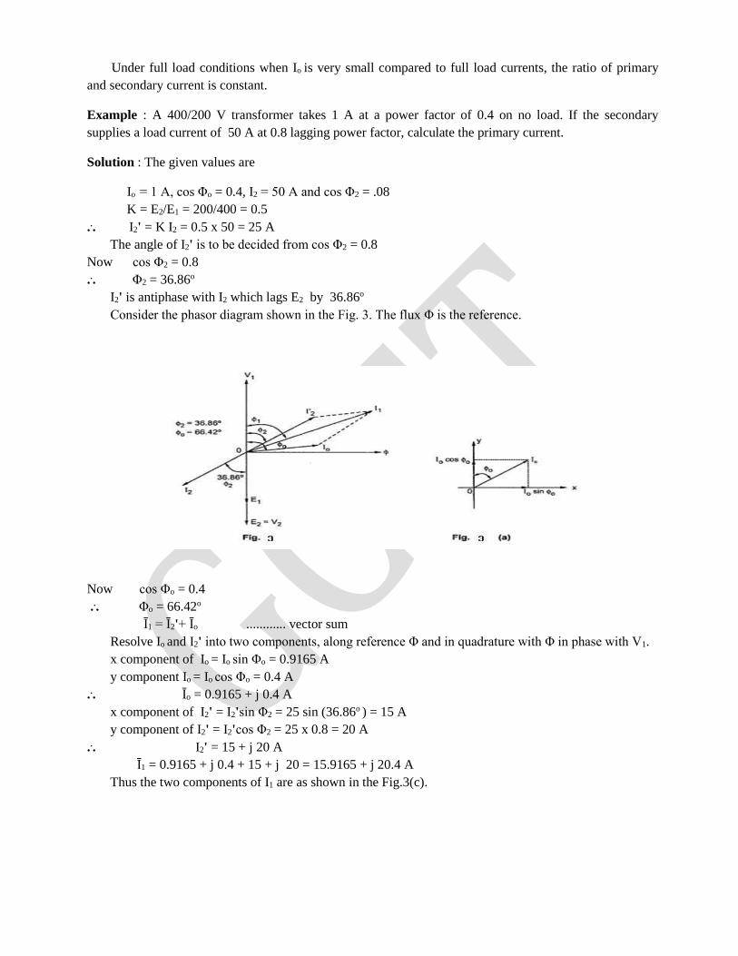
Consider the phasor diagram shown in the Fig. 3. The flux Φ is the reference.
Now cos Φo = 0.4
... Φo = 66.42o
Ī1 = Ī2'+ Īo ............ vector sum
Resolve Io and I2' into two components, along reference Φ and in quadrature with Φ in phase with V1.
x component of Io = Io sin Φo = 0.9165 A
y component Io = Io cos Φo = 0.4 A
... Īo = 0.9165 + j 0.4 A
x component of I2' = I2'sin Φ2 = 25 sin (36.86o ) = 15 A
y component of I2' = I2'cos Φ2 = 25 x 0.8 = 20 A
... I2' = 15 + j 20 A
Ī1 = 0.9165 + j 0.4 + 15 + j 20 = 15.9165 + j 20.4 A
Thus the two components of I1 are as shown in the Fig.3(c).
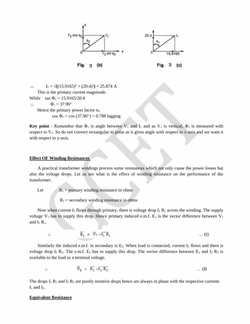
... I1 = √((15.9165)2 + (20.4)2) = 25.874 A
This is the primary current magnitude.
While tan Φ1 = 15.9165/20.4
... Φ1 = 37.96o
Hence the primary power factor is,
cos Φ1 = cos (37.96o ) = 0.788 lagging
Key point : Remember that Φ1 is angle between V1 and I1 and as V1 is vertical, Φ1 is measured with
respect to V1. So do not convert rectangular to polar as it gives angle with respect to x-axis and we want it
with respect to y-axis.
Effect OF Winding Resistances
A practical transformer windings process some resistances which not only cause the power losses but
also the voltage drops. Let us see what is the effect of winding resistance on the performance of the
transformer.
Let R1 = primary winding resistance in ohms
R2 = secondary winding resistance in ohms
Now when current I1 flows through primary, there is voltage drop I1 R1 across the winding. The supply
voltage V1 has to supply this drop. Hence primary induced e.m.f. E1 is the vector difference between V1
and I1 R1.
Similarly the induced e.m.f. in secondary is E2. When load is connected, current I2 flows and there is
voltage drop I2 R2. The e.m.f. E2 has to supply this drop. The vector difference between E2 and I2 R2 is
available to the load as a terminal voltage.
The drops I1 R1 and I2 R2 are purely resistive drops hence are always in phase with the respective currents
I1 and I2.
Equivalent Resistance
The resistance of the two windings can be transferred to any one side either primary or secondary
without affecting the performance of the transformer. The transfer of the resistances on any one side is
advantageous as it makes the calculations very easy. Let us see how to transfer the resistances on any one
side.
The total copper loss due to both the resistances can be obtained as,
total copper loss = I12 R1 + I2
2 R2
= I12 R1 +(I2
2/I12) R2
= I12R1 + (1/K2) R2 .......(3)
Where I2/I1 = 1/K neglecting no load current.
Now the expression (3) indicates that the total copper loss can be expressed as I12 R1 + I1
2 .R2/K2. This
means R2/K2 is the resistance value of R2 shifted to primary side which causes same copper loss with I1 as
R2 causes with. This value of resistance which R2 /K2 is the value of R2 referred to primary is called
equivalent resistance of secondary referred to primary. It is denoted as R2'.
R2' = R2 /K2 ........(4)
Hence the total resistance referred to primary is the addition of R1 and R2' called equivalent resistance
of transformer referred to primary and denoted as R1e.
= R1 + R2'= R1 + R2 /K2 .........(5)
This resistance R1e causes same copper loss with I1 as the total copper loss due to the individual
windings.
total copper loss = I12 R1e = I1
2 R1 + I22 R2 ......(6)
So equivalent resistance simplifies the calculations as we have to calculate parameters on one side
only.
Similarly it is possible to refer the equivalent resistance to secondary winding.
total copper loss = I12 R1 + I2
2 R2
= I22 (I1
2/I22) R1 + R2
= I22 ( K2 R1 + R2) ........(7)
Thus the resistance K2 R1 is primary resistance referred to secondary denoted as R1'.
R1' = K2 R1 .......(8)
Hence the total resistance referred to secondary is the addition of R2 and R1' called equivalent
resistance of transformer referred to secondary and denoted as R2e.
R2e = R2 + R1' = R2 + K2 R1 .........(9)
total copper loss = I22 R2e ........(10)
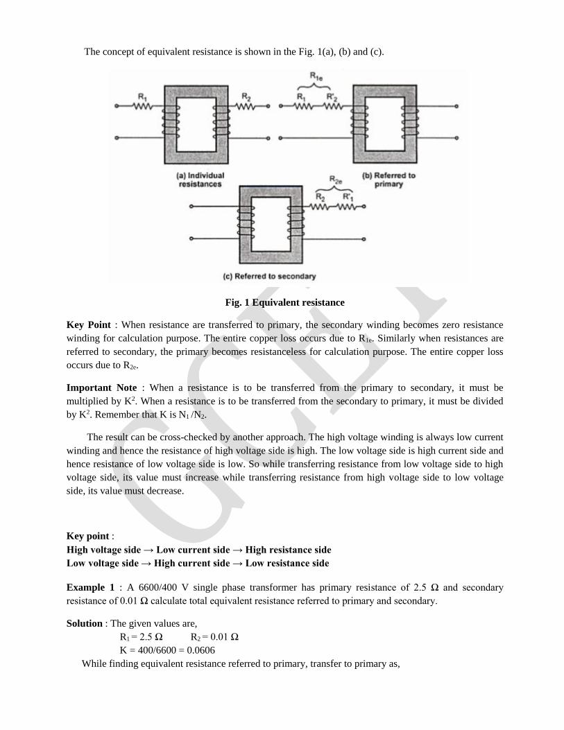
The concept of equivalent resistance is shown in the Fig. 1(a), (b) and (c).
Fig. 1 Equivalent resistance
Key Point : When resistance are transferred to primary, the secondary winding becomes zero resistance
winding for calculation purpose. The entire copper loss occurs due to R1e. Similarly when resistances are
referred to secondary, the primary becomes resistanceless for calculation purpose. The entire copper loss
occurs due to R2e.
Important Note : When a resistance is to be transferred from the primary to secondary, it must be
multiplied by K2. When a resistance is to be transferred from the secondary to primary, it must be divided
by K2. Remember that K is N1 /N2.
The result can be cross-checked by another approach. The high voltage winding is always low current
winding and hence the resistance of high voltage side is high. The low voltage side is high current side and
hence resistance of low voltage side is low. So while transferring resistance from low voltage side to high
voltage side, its value must increase while transferring resistance from high voltage side to low voltage
side, its value must decrease.
Key point :
High voltage side → Low current side → High resistance side
Low voltage side → High current side → Low resistance side
Example 1 : A 6600/400 V single phase transformer has primary resistance of 2.5 Ω and secondary
resistance of 0.01 Ω calculate total equivalent resistance referred to primary and secondary.
Solution : The given values are,
R1 = 2.5 Ω R2 = 0.01 Ω
K = 400/6600 = 0.0606
While finding equivalent resistance referred to primary, transfer to primary as,
R2'= R2 /K2 = 0.01/(0.0606)2 = 2.7225 Ω
R1e = R1 + R2' = 2.5 + 2.7225 = 5.2225 Ω
It can be observed that primary is high voltage hence high resistance side hence while transferring
from low voltage to on high voltage, its value increases.
To find total equivalent resistance referred to secondary, first calculate ,
R1'= K2 R1 = (0.0606)2 x 25 = 0.00918 Ω
R2e = R2 + R1' = 0.01 + 0.00918 = 0.01918 Ω
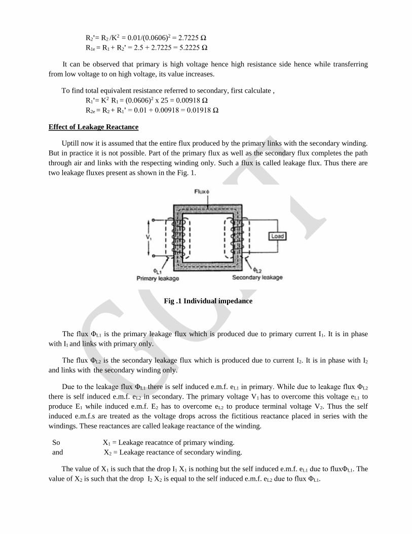
Effect of Leakage Reactance
Uptill now it is assumed that the entire flux produced by the primary links with the secondary winding.
But in practice it is not possible. Part of the primary flux as well as the secondary flux completes the path
through air and links with the respecting winding only. Such a flux is called leakage flux. Thus there are
two leakage fluxes present as shown in the Fig. 1.
Fig .1 Individual impedance
The flux ΦL1 is the primary leakage flux which is produced due to primary current I1. It is in phase
with I1 and links with primary only.
The flux ΦL2 is the secondary leakage flux which is produced due to current I2. It is in phase with I2
and links with the secondary winding only.
Due to the leakage flux ΦL1 there is self induced e.m.f. eL1 in primary. While due to leakage flux ΦL2
there is self induced e.m.f. eL2 in secondary. The primary voltage V1 has to overcome this voltage eL1 to
produce E1 while induced e.m.f. E2 has to overcome eL2 to produce terminal voltage V2. Thus the self
induced e.m.f.s are treated as the voltage drops across the fictitious reactance placed in series with the
windings. These reactances are called leakage reactance of the winding.
So X1 = Leakage reacatnce of primary winding.
and X2 = Leakage reactance of secondary winding.
The value of X1 is such that the drop I1 X1 is nothing but the self induced e.m.f. eL1 due to fluxΦL1. The
value of X2 is such that the drop I2 X2 is equal to the self induced e.m.f. eL2 due to flux ΦL1.
Leakage fluxes with the respective windings only and not to both the windings. To reduce the leakage,
as mentioned, int eh construction both the winding's are placed on same limb rather than on separate limbs.
Equivalent Leakage Reactance
Similar to the resistances, the leakage reactances also can be transferred from primary to secondary or
viceversa. The relation through K2 remains same for the transfer of recatnaces as it is studied earlier for the
resistances.
Let X1 is leakage reactance of primary and X2 is leakage reactance of secondary.
Then the total leakage reacatance referred to primary is X1e given by,
X1e = X1 + X2' where X2' = X2/K2
While the total leakage reacatnce referred to secondary is given by ,
X2e = X2 + X1' where X1' = K2 X1
And K = N2/N1 =transformation ratio
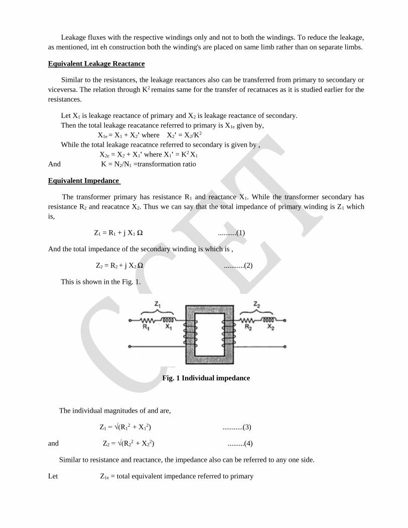
Equivalent Impedance
The transformer primary has resistance R1 and reactance X1. While the transformer secondary has
resistance R2 and reacatnce X2. Thus we can say that the total impedance of primary winding is Z1 which
is,
Z1 = R1 + j X1 Ω ..........(1)
And the total impedance of the secondary winding is which is ,
Z2 = R2 + j X2 Ω ...........(2)
This is shown in the Fig. 1.
Fig. 1 Individual impedance
The individual magnitudes of and are,
Z1 = √(R12 + X1
2) ...........(3)
and Z2 = √(R22 + X2
2) .........(4)
Similar to resistance and reactance, the impedance also can be referred to any one side.
Let Z1e = total equivalent impedance referred to primary
then Z1e = R1e + j X1e
Z1e = Z1 + Z2' = Z1 + Z2/K2 ............(5)
Similarly Z2e = total equivalent impedance referred to secondary
then Z2e = R2e + j X2e
Z2e = Z2 + Z1' = Z2 + K2 Z1 ............(6)
The magnitude of Z1e and Z2e are,
Z1e = √(R1e2 + X1e
2) ........(7)
and Z2e = √(R2e2 + X2e
2) ...........(8)
It can be denoted that,
Z2e = K2 Z1e and Z1e = Z2e /K2
The concept of equivalent impedance is shown in the Fig. 2.
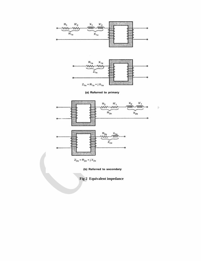
Fig 2 Equivalent impedance
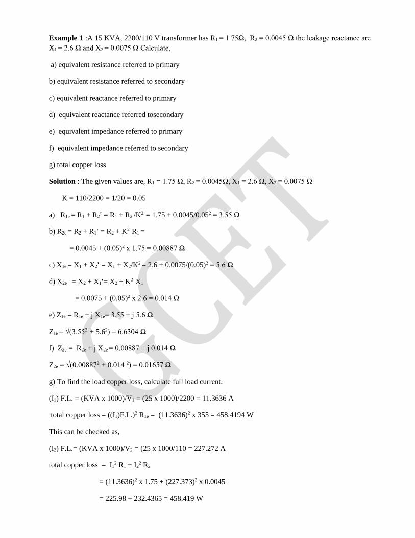
Example 1 :A 15 KVA, 2200/110 V transformer has R1 = 1.75Ω, R2 = 0.0045 Ω the leakage reactance are
X1 = 2.6 Ω and X2 = 0.0075 Ω Calculate,
a) equivalent resistance referred to primary
b) equivalent resistance referred to secondary
c) equivalent reactance referred to primary
d) equivalent reactance referred tosecondary
e) equivalent impedance referred to primary
f) equivalent impedance referred to secondary
g) total copper loss
Solution : The given values are, R1 = 1.75 Ω, R2 = 0.0045Ω, X1 = 2.6 Ω, X2 = 0.0075 Ω
K = 110/2200 = 1/20 = 0.05
a) R1e = R1 + R2' = R1 + R2 /K2 = 1.75 + 0.0045/0.052 = 3.55 Ω
b) R2e = R2 + R1' = R2 + K2 R1 =
= 0.0045 + (0.05)2 x 1.75 = 0.00887 Ω
c) X1e = X1 + X2' = X1 + X2/K2 = 2.6 + 0.0075/(0.05)2 = 5.6 Ω
d) X2e = X2 + X1'= X2 + K2 X1
= 0.0075 + (0.05)2 x 2.6 = 0.014 Ω
e) Z1e = R1e + j X1e= 3.55 + j 5.6 Ω
Z1e = √(3.552 + 5.62) = 6.6304 Ω
f) Z2e = R2e + j X2e = 0.00887 + j 0.014 Ω
Z2e = √(0.008872 + 0.014 2) = 0.01657 Ω
g) To find the load copper loss, calculate full load current.
(I1) F.L. = (KVA x 1000)/V1 = (25 x 1000)/2200 = 11.3636 A
total copper loss = ((I1)F.L.)2 R1e = (11.3636)2 x 355 = 458.4194 W
This can be checked as,
(I2) F.L.= (KVA x 1000)/V2 = (25 x 1000/110 = 227.272 A
total copper loss = I12 R1 + I2
2 R2
= (11.3636)2 x 1.75 + (227.373)2 x 0.0045
= 225.98 + 232.4365 = 458.419 W
Equivalent circuit of Transformer
The term equivalent circuit of a machine means the combination of fixed and variable resistances and
reactances, which exactly simulates performance and working of the machine.
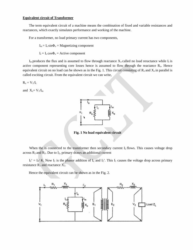
For a transformer, no load primary current has two components,
Im = Io sinΦo = Magnetizing component
Ic = Io cosΦo = Active component
Im produces the flux and is assumed to flow through reactance Xo called no load reractance while Ic is
active component representing core losses hence is assumed to flow through the reactance Ro. Hence
equivalent circuit on no load can be shown as in the Fig. 1. This circuit consisting of Ro and Xo in parallel is
called exciting circuit. From the equivalent circuit we can write,
Ro = V1/Ic
and Xo= V1/Im
Fig. 1 No load equivalent circuit
When the is connected to the transformer then secondary current I2 flows. This causes voltage drop
across R2 and R2. Due to I2, primary draws an additional current
I2' = I2/ K. Now I1 is the phasor addition of Io and I2'. This I1 causes the voltage drop across primary
resistance R1 and reactance X1.
Hence the equivalent circuit can be shown as in the Fig. 2.
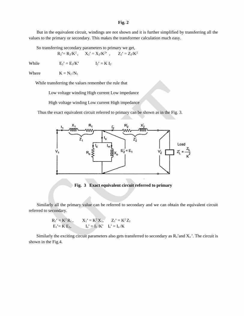
Fig. 2
But in the equivalent circuit, windings are not shown and it is further simplified by transferring all the
values to the primary or secondary. This makes the transformer calculation much easy.
So transferring secondary parameters to primary we get,
R2'= R2/K2 , X2' = X2/K2' , Z2' = Z2/K2
While E2' = E2/K' I2' = K I2
Where K = N2 /N1
While transferring the values remember the rule that
Low voltage winding High current Low impedance
High voltage winding Low current High impedance
Thus the exact equivalent circuit referred to primary can be shown as in the Fig. 3.
Fig. 3 Exact equivalent circuit referred to primary
Similarly all the primary value can be referred to secondary and we can obtain the equivalent circuit
referred to secondary.
R1' = K2 R1 , X1' = K2 X1, Z1' = K2 Z1
E1'= K E1, Io' = I1 /K' Io' = Io /K
Similarly the exciting circuit parameters also gets transferred to secondary as Ro'and Xo '. The circuit is
shown in the Fig.4.
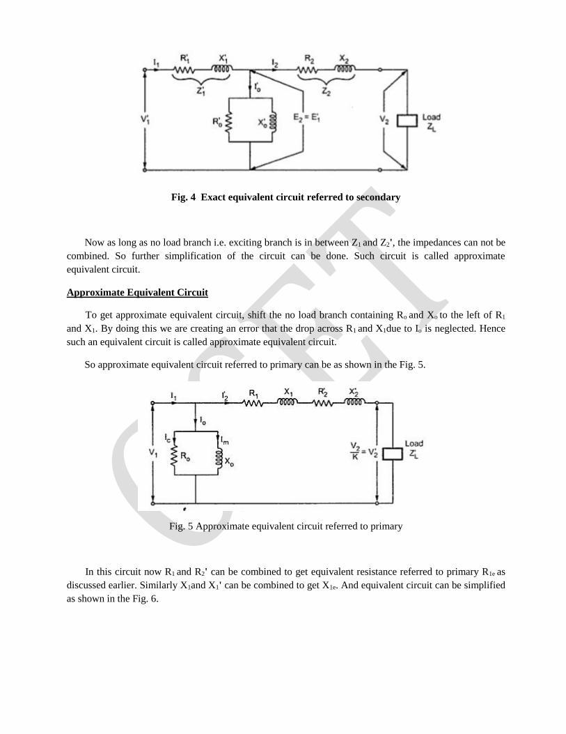
Fig. 4 Exact equivalent circuit referred to secondary
Now as long as no load branch i.e. exciting branch is in between Z1 and Z2', the impedances can not be
combined. So further simplification of the circuit can be done. Such circuit is called approximate
equivalent circuit.
Approximate Equivalent Circuit
To get approximate equivalent circuit, shift the no load branch containing Ro and Xo to the left of R1
and X1. By doing this we are creating an error that the drop across R1 and X1due to Io is neglected. Hence
such an equivalent circuit is called approximate equivalent circuit.
So approximate equivalent circuit referred to primary can be as shown in the Fig. 5.
Fig. 5 Approximate equivalent circuit referred to primary
In this circuit now R1 and R2' can be combined to get equivalent resistance referred to primary R1e as
discussed earlier. Similarly X1and X1' can be combined to get X1e. And equivalent circuit can be simplified
as shown in the Fig. 6.
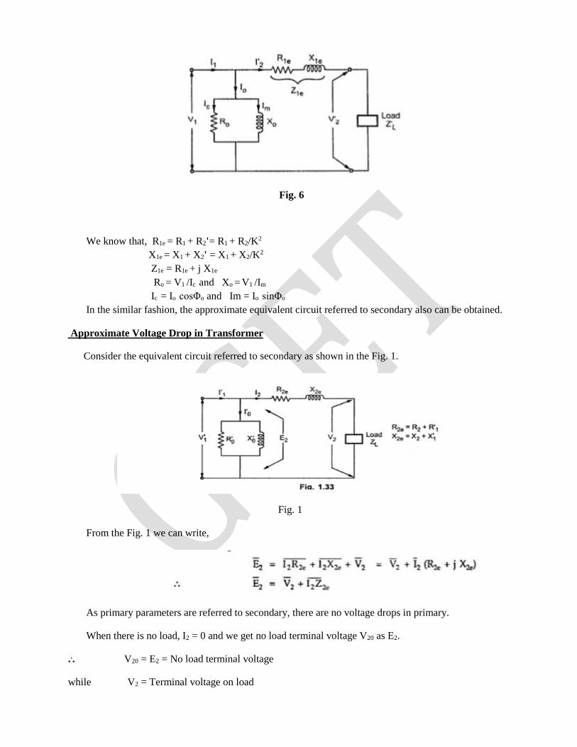
Fig. 6
We know that, R1e = R1 + R2'= R1 + R2/K2
X1e = X1 + X2' = X1 + X2/K2
Z1e = R1e + j X1e
Ro = V1 /Ic and Xo = V1 /Im
Ic = Io cosΦo and Im = Io sinΦo
In the similar fashion, the approximate equivalent circuit referred to secondary also can be obtained.
Approximate Voltage Drop in Transformer
Consider the equivalent circuit referred to secondary as shown in the Fig. 1.
Fig. 1
From the Fig. 1 we can write,
As primary parameters are referred to secondary, there are no voltage drops in primary.
When there is no load, I2 = 0 and we get no load terminal voltage V20 as E2.
... V20 = E2 = No load terminal voltage
while V2 = Terminal voltage on load
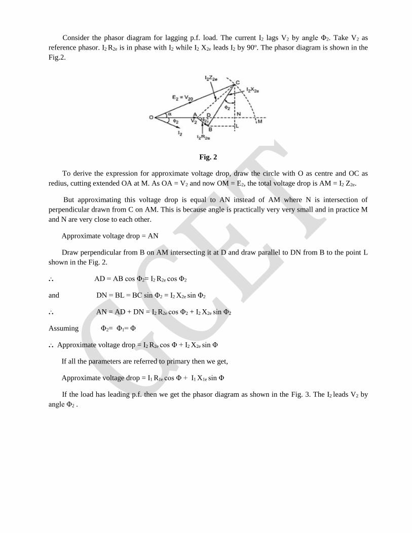
Consider the phasor diagram for lagging p.f. load. The current I2 lags V2 by angle Φ2. Take V2 as
reference phasor. I2 R2e is in phase with I2 while I2 X2e leads I2 by 90o. The phasor diagram is shown in the
Fig.2.
Fig. 2
To derive the expression for approximate voltage drop, draw the circle with O as centre and OC as
redius, cutting extended OA at M. As OA = V2 and now OM = E2, the total voltage drop is AM = I2 Z2e.
But approximating this voltage drop is equal to AN instead of AM where N is intersection of
perpendicular drawn from C on AM. This is because angle is practically very very small and in practice M
and N are very close to each other.
Approximate voltage drop = AN
Draw perpendicular from B on AM intersecting it at D and draw parallel to DN from B to the point L
shown in the Fig. 2.
... AD = AB cos Φ2= I2 R2e cos Φ2
and DN = BL = BC sin Φ2 = I2 X2e sin Φ2
... AN = AD + DN = I2 R2e cos Φ2 + I2 X2e sin Φ2
Assuming Φ2= Φ1= Φ
... Approximate voltage drop = I2 R2e cos Φ + I2 X2e sin Φ
If all the parameters are referred to primary then we get,
Approximate voltage drop = I1 R1e cos Φ + I1 X1e sin Φ
If the load has leading p.f. then we get the phasor diagram as shown in the Fig. 3. The I2 leads V2 by
angle Φ2 .
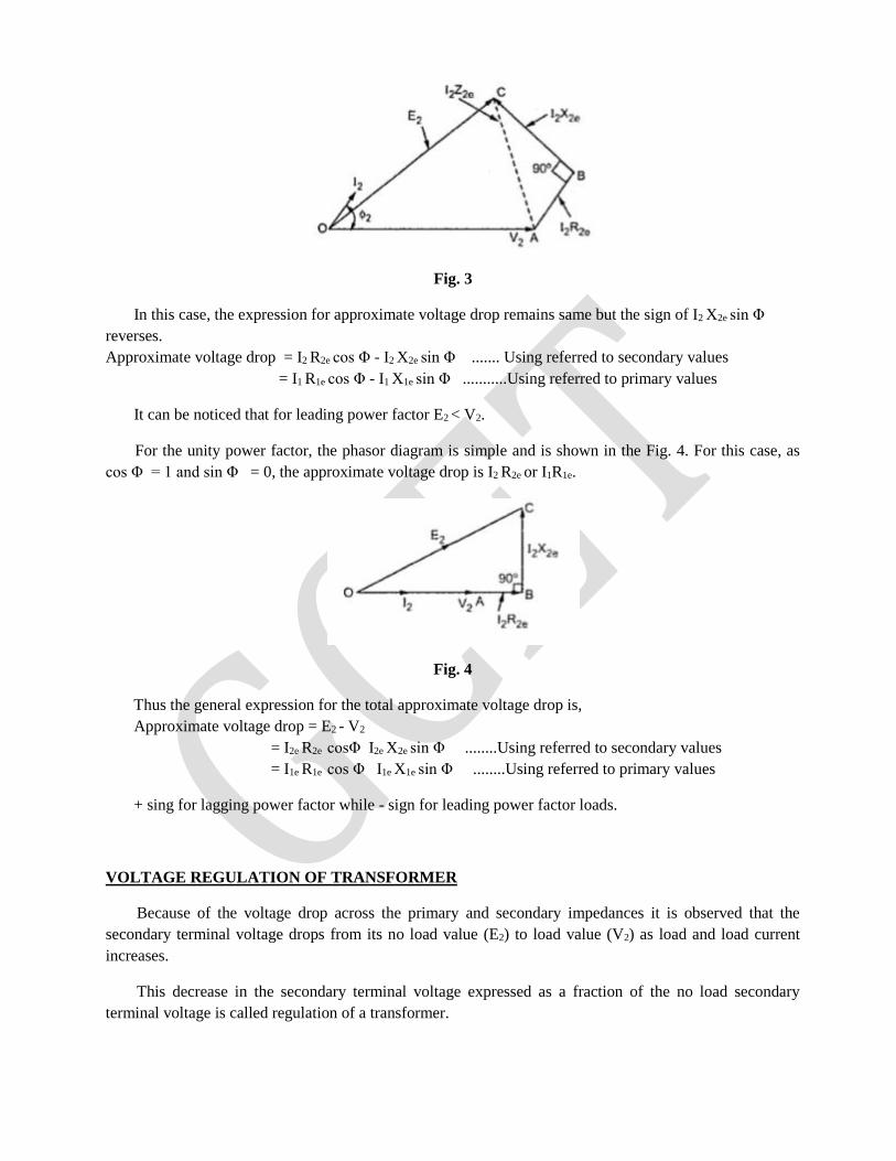
Fig. 3
In this case, the expression for approximate voltage drop remains same but the sign of I2 X2e sin Φ
reverses.
Approximate voltage drop = I2 R2e cos Φ - I2 X2e sin Φ ....... Using referred to secondary values
= I1 R1e cos Φ - I1 X1e sin Φ ...........Using referred to primary values
It can be noticed that for leading power factor E2 < V2.
For the unity power factor, the phasor diagram is simple and is shown in the Fig. 4. For this case, as
cos Φ = 1 and sin Φ = 0, the approximate voltage drop is I2 R2e or I1R1e.
Fig. 4
Thus the general expression for the total approximate voltage drop is,
Approximate voltage drop = E2 - V2
= I2e R2e cosΦ I2e X2e sin Φ ........Using referred to secondary values
= I1e R1e cos Φ I1e X1e sin Φ ........Using referred to primary values
+ sing for lagging power factor while - sign for leading power factor loads.
VOLTAGE REGULATION OF TRANSFORMER
Because of the voltage drop across the primary and secondary impedances it is observed that the
secondary terminal voltage drops from its no load value (E2) to load value (V2) as load and load current
increases.
This decrease in the secondary terminal voltage expressed as a fraction of the no load secondary
terminal voltage is called regulation of a transformer.
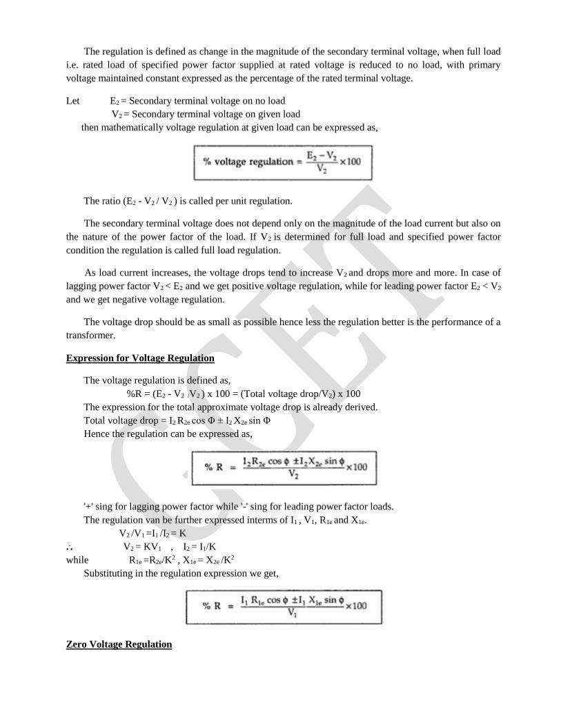
The regulation is defined as change in the magnitude of the secondary terminal voltage, when full load
i.e. rated load of specified power factor supplied at rated voltage is reduced to no load, with primary
voltage maintained constant expressed as the percentage of the rated terminal voltage.
Let E2 = Secondary terminal voltage on no load
V2 = Secondary terminal voltage on given load
then mathematically voltage regulation at given load can be expressed as,
The ratio (E2 - V2 / V2 ) is called per unit regulation.
The secondary terminal voltage does not depend only on the magnitude of the load current but also on
the nature of the power factor of the load. If V2 is determined for full load and specified power factor
condition the regulation is called full load regulation.
As load current increases, the voltage drops tend to increase V2 and drops more and more. In case of
lagging power factor V2 < E2 and we get positive voltage regulation, while for leading power factor E2 < V2
and we get negative voltage regulation.
The voltage drop should be as small as possible hence less the regulation better is the performance of a
transformer.
Expression for Voltage Regulation
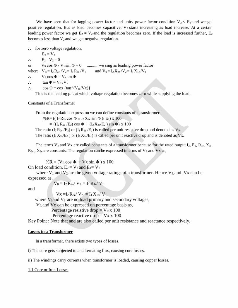
The voltage regulation is defined as,
%R = (E2 - V2 /V2 ) x 100 = (Total voltage drop/V2) x 100
The expression for the total approximate voltage drop is already derived.
Total voltage drop = I2 R2e cos Φ ± I2 X2e sin Φ
Hence the regulation can be expressed as,
'+' sing for lagging power factor while '-' sing for leading power factor loads.
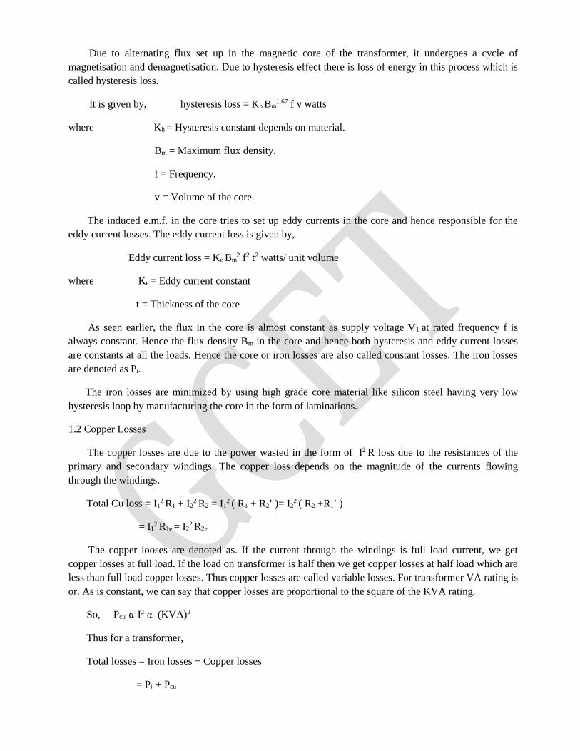
The regulation van be further expressed interms of I1 , V1, R1e and X1e.
V2 /V1 =I1 /I2 = K
... V2 = KV1 , I2 = I1/K
while R1e =R2e/K2 , X1e = X2e /K2
Substituting in the regulation expression we get,
Zero Voltage Regulation
We have seen that for lagging power factor and unity power factor condition V2 < E2 and we get
positive regulation. But as load becomes capacitive, V2 starts increasing as load increase. At a certain
leading power factor we get E2 = V2 and the regulation becomes zero. If the load is increased further, E2
becomes less than V2 and we get negative regulation.
... for zero voltage regulation,
E2 = V2
... E2 - V2 = 0
or VR cos Φ - Vx sin Φ = 0 .......... -ve sing as leading power factor
where VR = I2 R2e /V2 = I1 R1e /V1 and Vx = I2 X2e /V2 = I1 X1e /V1
... VR cos Φ = Vx sin Φ
... tan Φ = VR /Vx
... cos Φ = cos tan-1(VR /Vx)
This is the leading p.f. at which voltage regulation becomes zero while supplying the load.
Constants of a Transformer
From the regulation expression we can define constants of a transformer.
%R= (( I2 R2e cos Φ ± I2 X2e sin Φ )/ E2) x 100
= (I2 R2e /E2) cos Φ ± (I2 X2e/E2 ) sin Φ x 100
The ratio (I2 R2e /E2) or (I1 R1e /E1) is called per unit resistive drop and denoted as VR.
The ratio (I2 X2e/E2 ) or (I1 X1e/E1) is called per unit reactive drop and is denoted as Vx.
The terms VR and Vx are called constants of a transformer because for the rated output I2, E2, R1e, X1e,
R2e , X2e are constants. The regulation can be expressed interms of VR and Vx as,
%R = (VR cos Φ ± Vx sin Φ ) x 100
On load condition, E2 = V2 and E1= V1
where V1 and V2 are the given voltage ratings of a transformer. Hence VR and Vx can be
expressed as,
VR = I2 R2e/ V2 = I1 R1e/ V1
and
Vx =I2 R2e/ V2 = I1 X1e/ V1
where V1and V2 are no load primary and secondary voltages,
VR and Vx can be expressed on percentage basis as,
Percentage resistive drop = VR x 100
Percentage reactive drop = Vx x 100
Key Point : Note that and are also called per unit resistance and reactance respectively.
Losses in a Transformer
In a transformer, there exists two types of losses.
i) The core gets subjected to an alternating flux, causing core losses.
ii) The windings carry currents when transformer is loaded, causing copper losses.
1.1 Core or Iron Losses
Due to alternating flux set up in the magnetic core of the transformer, it undergoes a cycle of
magnetisation and demagnetisation. Due to hysteresis effect there is loss of energy in this process which is
called hysteresis loss.
It is given by, hysteresis loss = Kh Bm
1.67 f v watts
where Kh = Hysteresis constant depends on material.
Bm = Maximum flux density.
f = Frequency.
v = Volume of the core.
The induced e.m.f. in the core tries to set up eddy currents in the core and hence responsible for the
eddy current losses. The eddy current loss is given by,
Eddy current loss = Ke Bm
2 f2 t2 watts/ unit volume
where Ke = Eddy current constant
t = Thickness of the core
As seen earlier, the flux in the core is almost constant as supply voltage V1 at rated frequency f is
always constant. Hence the flux density Bm in the core and hence both hysteresis and eddy current losses
are constants at all the loads. Hence the core or iron losses are also called constant losses. The iron losses
are denoted as Pi.
The iron losses are minimized by using high grade core material like silicon steel having very low
hysteresis loop by manufacturing the core in the form of laminations.
1.2 Copper Losses
The copper losses are due to the power wasted in the form of I2 R loss due to the resistances of the
primary and secondary windings. The copper loss depends on the magnitude of the currents flowing
through the windings.
Total Cu loss = I12 R1 + I2
2 R2 = I1
2 ( R1 + R2' )= I2
2 ( R2 +R1' )
= I12
R1e = I22
R2e
The copper looses are denoted as. If the current through the windings is full load current, we get
copper losses at full load. If the load on transformer is half then we get copper losses at half load which are
less than full load copper losses. Thus copper losses are called variable losses. For transformer VA rating is
or. As is constant, we can say that copper losses are proportional to the square of the KVA rating.
So, Pcu α I2 α (KVA)2
Thus for a transformer,
Total losses = Iron losses + Copper losses
= Pi + Pcu

Key point : It is seen that the iron losses depend on the supply voltage while the copper losses depend on
the current. The losses are not dependent on the phase angle between voltage and current. Hence the rating
of the transformer is expressed as a product of voltage and current and called VA rating of transformer. It
is not expressed in watts or kilo watts. Most of the times, rating is expressed in KVA.
Losses: Additional Study:
Transformer losses are divided into losses in the windings, termed copper loss, and those in the
magnetic circuit, termed iron loss. Losses in the transformer arise from: Winding resistance
Current flowing through the windings causes resistive heating of the conductors. At higher
frequencies, skin effect and proximity effect create additional winding resistance and losses.
Hysteresis losses
Each time the magnetic field is reversed, a small amount of energy is lost due to hysteresis within
the core. For a given core material, the loss is proportional to the frequency, and is a function of
the peak flux density to which it is subjected.[42]
Eddy currents
Ferromagnetic materials are also good conductors and a core made from such a material also
constitutes a single short-circuited turn throughout its entire length. Eddy currents therefore
circulate within the core in a plane normal to the flux, and are responsible for resistive heating of
the core material. The eddy current loss is a complex function of the square of supply frequency
and inverse square of the material thickness.[42] Eddy current losses can be reduced by making the
core of a stack of plates electrically insulated from each other, rather than a solid block; all
transformers operating at low frequencies use laminated or similar cores.
Magnetostriction
Magnetic flux in a ferromagnetic material, such as the core, causes it to physically expand and
contract slightly with each cycle of the magnetic field, an effect known as magnetostriction. This
produces the buzzing sound commonly associated with transformers[29] that can cause losses due to
frictional heating. This buzzing is particularly familiar from low-frequency (50 Hz or 60 Hz) mains
hum, and high-frequency (15,734 Hz (NTSC) or 15,625 Hz (PAL)) CRT noise.
Mechanical losses
In addition to magnetostriction, the alternating magnetic field causes fluctuating forces between the
primary and secondary windings. These incite vibrations within nearby metalwork, adding to the
buzzing noise and consuming a small amount of power.[43]
Stray losses
Leakage inductance is by itself largely lossless, since energy supplied to its magnetic fields is
returned to the supply with the next half-cycle. However, any leakage flux that intercepts nearby
conductive materials such as the transformer's support structure will give rise to eddy currents and
be converted to heat.[44] There are also radiative losses due to the oscillating magnetic field but
these are usually small.
EFFICIENCY OF A TRANSFORMER
Due to the losses in a transformer, the output power of a transformer is less than the input power
supplied.
... Power output = Power input - Total losses
... Power input = Power output + Total losses
= Power output + Pi + Pcu
The efficiency of any device is defined as the ratio of the power output to power input. So for a
transformer the efficiency can be expresses as,
η = Power output/power input
... η = Power output/(power output + Pi + Pcu )
Now power output = V2 I2 cos Φ
where cos Φ = Load power factor
The transformer supplies full load of current I2 and with terminal voltage V2.
Pcu = Copper losses on full load = I22 R2e
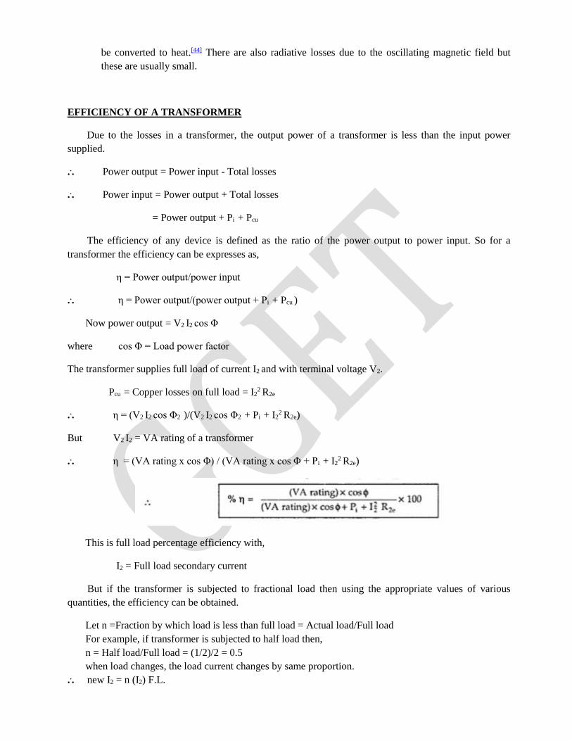
... η = (V2 I2 cos Φ2 )/(V2 I2 cos Φ2 + Pi + I22
R2e)
But V2 I2 = VA rating of a transformer
... η = (VA rating x cos Φ) / (VA rating x cos Φ + Pi + I22
R2e)
This is full load percentage efficiency with,
I2 = Full load secondary current
But if the transformer is subjected to fractional load then using the appropriate values of various
quantities, the efficiency can be obtained.
Let n =Fraction by which load is less than full load = Actual load/Full load
For example, if transformer is subjected to half load then,
n = Half load/Full load = (1/2)/2 = 0.5
when load changes, the load current changes by same proportion.
... new I2 = n (I2) F.L.
Similarly the output V2 I2 cosΦ2 also reduces by the same fraction. Thus fraction of VA rating is
available at the output.
Similarly as copper losses are proportional to square of current then,
new Pcu = n2 (Pcu ) F.L.
Key Point : So copper losses get reduced by n2.
In general for fractional load the efficiency is given by,
where n = Fraction by which load power factor lagging, leading and unity the efficiency expression
does not change, and remains same.
O.C. AND S.C. TESTS ON SINGLE PHASE TRANSFORMER
The efficiency and regulation of a transformer on any load condition and at any power factor condition
can be predetermined by indirect loading method. In this method, the actual load is not used on
transformer. But the equivalent circuit parameters of a transformer are determined by conducting two tests
on a transformer which are,
1. Open circuit test (O.C Test)
2. Short circuit test (S.C.Test)
The parameters calculated from these test results are effective in determining the regulation and
efficiency of a transformer at any load and power factor condition, without actually loading the
transformer. The advantage of this method is that without much power loss the tests can be performed and
results can be obtained. Let us discuss in detail how to perform these tests and how to use the results to
calculate equivalent circuit parameters.
1.1 Open Circuit Test (O.C. Test)
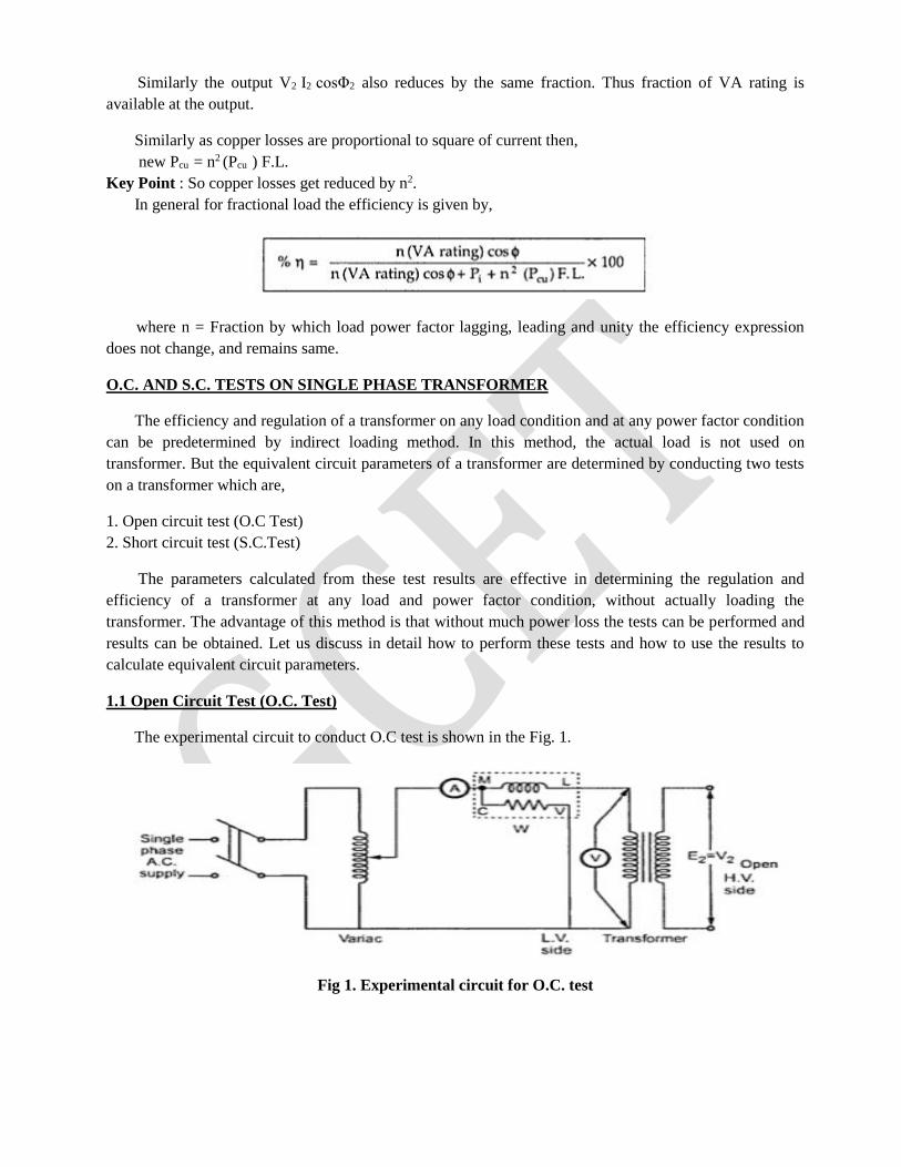
The experimental circuit to conduct O.C test is shown in the Fig. 1.
Fig 1. Experimental circuit for O.C. test
The transformer primary is connected to a.c. supply through ammeter, wattmeter and variac. The
secondary of transformer is kept open. Usually low voltage side is used as primary and high voltage side as
secondary to conduct O.C test.
The primary is excited by rated voltage, which is adjusted precisely with the help of a variac. The
wattmeter measures input power. The ammeter measures input current. The voltemeter gives the value of
rated primary voltage applied at rated frequency.
Sometimes a voltmeter may be connected across secondary to measure secondary voltage which is V2
= E2 when primary is supplied with rated voltage. As voltmeter resistance is very high, though voltmeter is
connected, secondary is treated to be open circuit as voltmeter current is always negligibly small.
When the primary voltage is adjusted to its rated value with the help of variac, readings of ammeter and
wattmeter are to be recorded.
The observation table is as follows
Vo = Rated voltage
Wo = Input power
Io = Input current = no load current
As transformer secondary is open, it is on no load. So current drawn by the primary is no load current
Io. The two components of this no load current are,
Im = Io sin Φo
Ic = Io cos Φo
where cos Φo = No load power factor
And hence power input can be written as,
Wo = Vo Io cos Φo
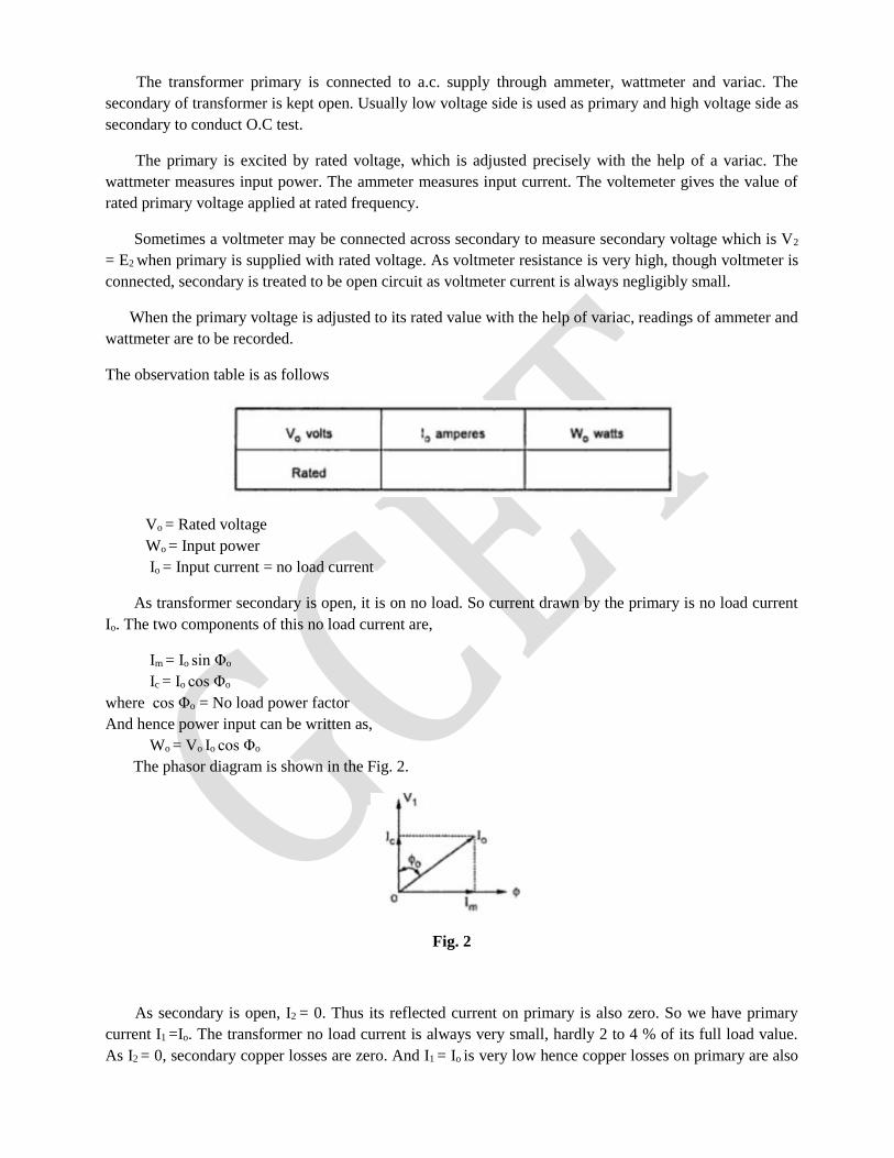
The phasor diagram is shown in the Fig. 2.
Fig. 2
As secondary is open, I2 = 0. Thus its reflected current on primary is also zero. So we have primary
current I1 =Io. The transformer no load current is always very small, hardly 2 to 4 % of its full load value.
As I2 = 0, secondary copper losses are zero. And I1 = Io is very low hence copper losses on primary are also
very very low. Thus the total copper losses in O.C. test are negligibly small. As against this the input
voltage is rated at rated frequency hence flux density in the core is at its maximum value. Hence iron losses
are at rated voltage. As output power is zero and copper losses are very low, the total input power is used
to supply iron losses. This power is measured by the wattmeter i.e. Wo. Hence the wattmeter in O.C. test
gives iron losses which remain constant for all the loads.
... Wo = Pi = Iron losses
Calculations : We know that,
Wo = Vo Io cos Φ
cos Φo = Wo /(Vo Io ) = no load power factor
Once cos Φo is known we can obtain,
Ic = Io cos Φo
and Im = Io sin Φo
Once Ic and Im are known we can determine exciting circuit parameters as,
Ro = Vo /Ic Ω
and Xo = Vo /Im Ω
Key Point : The no load power factor cos Φo is very low hence wattmeter used must be low power factor
type otherwise there might be error in the results. If the meters are connected on secondary and primary is
kept open then from O.C. test we get Ro' and Xo' with which we can obtain Ro and Xo knowing the
transformation ratio K.
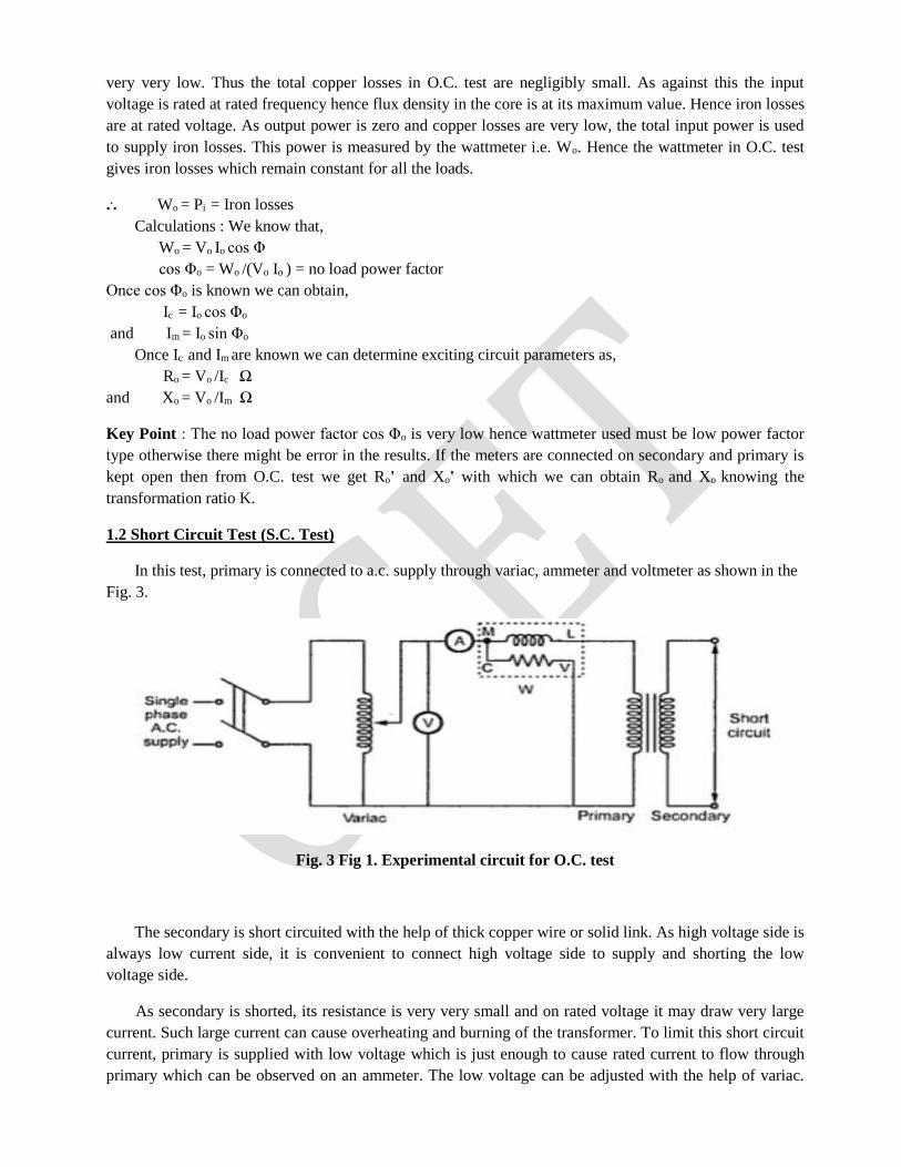
1.2 Short Circuit Test (S.C. Test)
In this test, primary is connected to a.c. supply through variac, ammeter and voltmeter as shown in the
Fig. 3.
Fig. 3 Fig 1. Experimental circuit for O.C. test
The secondary is short circuited with the help of thick copper wire or solid link. As high voltage side is
always low current side, it is convenient to connect high voltage side to supply and shorting the low
voltage side.
As secondary is shorted, its resistance is very very small and on rated voltage it may draw very large
current. Such large current can cause overheating and burning of the transformer. To limit this short circuit
current, primary is supplied with low voltage which is just enough to cause rated current to flow through
primary which can be observed on an ammeter. The low voltage can be adjusted with the help of variac.
Hence this test is also called low voltage test or reduced voltage test. The wattmeter reading as well as
voltmeter, ammeter readings are recorded. The observation table is as follows,
Now the current flowing through the windings are rated current hence the total copper loss is full load
copper loss. Now the voltage supplied is low which is a small fraction of the rated voltage. The iron losses
are function of applied voltage. So the iron losses in reduced voltage test are very small. Hence the
wattmeter reading is the power loss which is equal to full load copper losses as iron losses are very low.
... Wsc = (Pcu) F.L. = Full load copper loss
Calculations : From S.C. test readings we can write,
Wsc = Vsc Isc cos Φsc
... cos Φsc = Vsc Isc /Wsc = short circuit power factor
Wsc = Isc2 R1e = copper loss
... R1e =Wsc /Isc2
while Z1e =Vsc /Isc = √(R1e2 + X1e
2)
... X1e = √(Z1e
2 - R1e2)
Thus we get the equivalent circuit parameters R1e, X1e and Z1e. Knowing the transformation ratio K, the
equivalent circuit parameters referred to secondary also can be obtained.
Important Note : If the transformer is step up transformer, its primary is L.V. while secondary is H.V.
winding. In S.C. test, supply is given to H.V. winding and L.V is shorted. In such case we connect meters
on H.V. side which is transformer secondary through for S.C. test purpose H.V side acts as primary. In
such case the parameters calculated from S.C. test readings are referred to secondary which are R2e, Z2e and
X2e. So before doing calculations it is necessary to find out where the readings are recorded on transformer
primary or secondary and accordingly the parameters are to be determined. In step down transformer,
primary is high voltage itself to which supply is given in S.C. test. So in such case test results give us
parameters referred to primary i.e. R1e, Z1e and X1e.
Key point : In short, if meters are connected to primary of transformer in S.C. test, calculations give us R1e
and Z1e if meters are connected to secondary of transformer in S.C. test calculations give us R2e and Z2e.
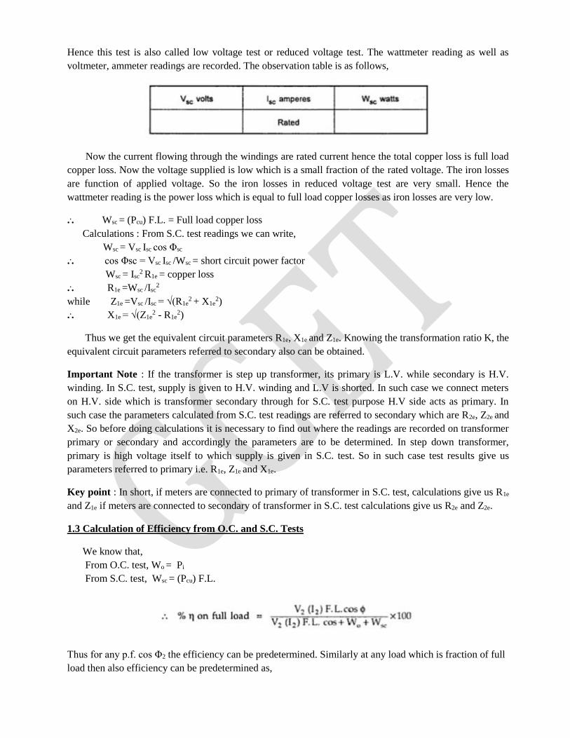
1.3 Calculation of Efficiency from O.C. and S.C. Tests
We know that,
From O.C. test, Wo = Pi
From S.C. test, Wsc = (Pcu) F.L.
Thus for any p.f. cos Φ2 the efficiency can be predetermined. Similarly at any load which is fraction of full
load then also efficiency can be predetermined as,
where n = fraction of full load
where I2= n (I2) F.L.
1.4 Calculation of Regulation
From S.C. test we get the equivalent circuit parameters referred to primary or secondary.
The rated voltages V1, V2 and rated currents (I1) F.L. and (I2) F.L. are known for the given transformer.
Hence the regulation can be determined as,
where I1, I2 are rated currents for full load regulation.
For any other load the currents I1, I2 must be changed by fraction n.
... I1, I2 at any other load = n (I1) F.L., n (I2) F.L.
Key Point : Thus regulation at any load and any power factor can be predetermined, without actually
loading the transformer.
Example 1 : A 5 KVA, 500/250 V, 50 Hz, single phase transformer gave the following readings,
O.C. Test : 500 V, 1 A, 50 W (L.V. side open)
S.C. Test : 25 V, 10 A, 60 W (L.V. side shorted)
Determine : i) The efficiency on full load, 0.8 lagging p.f.
ii) The voltage regulation on full load, 0.8 leading p.f.
iii) The efficiency on 60% of full load, 0.8 leading p.f.
iv) Draw the equivalent circuit referred to primary and insert all the values in it.
Solution : In both the tests, meters are on H.V. side which is primary of the transformer. Hence the
parameters obtained from test results will be referred to primary.
From O.C. test, Vo = 500 V, Io = 1 A, Wo= 50 W
... cos Φo = Wo/Vo Io = 50/(500x1) = 0.1
... Ic = Io cos = 1 x 0.1 = 0.1 A
and Im = Io sin Φo = 1 x 0.9949 = 0.9949 A
... Ro =Vo /Ic = 500/0.1 = 5000 Ω
and Xo = Vo/Im = 500/0.9949 = 502.52 Ω
and Wo = Pi= iron losses = 50 W
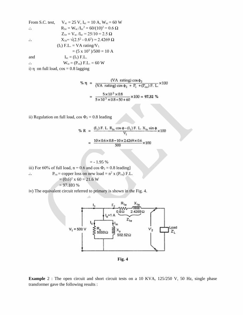
From S.C. test, Vsc = 25 V, Isc = 10 A, Wsc = 60 W
... R1e = Wsc /Isc2 = 60/(10)2 = 0.6 Ω
Z1e = Vsc /Isc = 25/10 = 2.5 Ω
... X1e= √(2.52 - 0.62) = 2.4269 Ω
(I1) F.L. = VA rating/V1
= (5 x 10³ )/500 = 10 A
and Isc = (I1) F.L.
... Wsc = (Pcu) F.L. = 60 W
i) η on full load, cos = 0.8 lagging
ii) Regulation on full load, cos Φ2 = 0.8 leading
= - 1.95 %
iii) For 60% of full load, n = 0.6 and cos Φ2 = 0.8 leading]
... Pcu = copper loss on new load = n2 x (Pcu) F.L.
= (0.6)2 x 60 = 21.6 W
= 97.103 %
iv) The equivalent circuit referred to primary is shown in the Fig. 4.
Fig. 4
Example 2 : The open circuit and short circuit tests on a 10 KVA, 125/250 V, 50 Hz, single phase
transformer gave the following results :
O.C. test : 125 V, 0.6 A, 50 W (on L.V. side)
S.C. test : 15 V, 30 A. 100 W (on H.V. side)
Calculate : i) copper loss on full load
ii) full load efficiency at 0.8 leading p.f.
iii) half load efficiency at 0.8 leading p.f.
iv) regulation at full load, 0.9 leading p.f.
Solution : From O.C. test we can weite,
Wo = Pi = 50 W = Iron loss
From S.C. test we can find the parameters of equivalent circuit. Now S.C. test is conducted on H.V.
side i.e. meters are on H.V. side which is transformer secondary. Hence parameters from S.C. test results
will be referred to secondary.
Vsc = 15 V, Isc = 30 A, Wsc = 100 W
... R2e = Wsc/(Isc)2 =10/(30)2 = 0.111Ω
Z1e = Vsc /Isc = 15/30 = 0.5 Ω
... X2e = √(Z2e2 - R2e
2) = 0.4875 Ω
i) Copper loss on full load
(I2) F.L. = VA rating/V2 = (10 x 103)/250 = 40 A
In short circuit test, Isc = 30 A and not equal to full load value 40 A.
Hence Wsc does not give copper loss on full load
... Wsc = Pcu at 30 A = 100 W
Now Pcu α I2
( Pcu at 30 A)/( Pcu at 40 A) = (30/40) 2
100/( Pcu at 40 A) = 900/1600
Pcu at 40 A = 177.78 W
... (Pcu) F.L. = 177.78 W
ii) Full load η , cos Φ2 = 0.8
iii) Half load η , cos Φ2 = 0.8
n = 0.5 as half load, (I2) H.L. = 0.5 x 40 =
= 97.69%
iv) Regulation at full load, cos Φ = 0.9 leading
= -1.8015%
The Polyphase Induction Motor
The polyphase induction motor is the most commonly used industrial motor, finding application in many
situations where speed regulation is not essential. It is simple and relatively inexpensive, and the absence
of sliding contacts in the squirrel-cage machine reduces maintenance to a minimum. There are two general
types of polyphase induction motors: the squirrel-cage type and the wound-rotor machine. Both motors
have an armature or stator structure similar to that of the alternating current generator, consisting of a
hollow cylinder of laminated sheet steel in which are punched longitudinal slots.
A symmetrical polyphase winding is laid in these slots which, when connected to a suitable voltage source,
produces a travelling MMF wave in the air gap, rotating at a synchronous speed equal to:
where f is the frequency and p the number of poles for which the stator is wound.
The squirrel-cage type of rotor is made up of sheet steel laminations keyed to the shaft and having slots
punched in the periphery. The number of slots in the rotor is never a multiple of the number in the stator,
thereby preventing rotor locking under light load conditions. The rotor conductors in most machines are
made of aluminum alloy either molded or extruded in place in the slots, with end rings being cast as an
integral part of the structure and connecting all bars at both ends. The air-gap length between rotor and
stator is kept as short as manufacturing tolerances will allow in order to minimize the
magnetizing current necessary for the production of normal air-gap flux. A simple twopole, three-phase,
squirrel-cage induction motor is diagrammed in Fig. 1.
The wound-rotor induction motor has a rotor similar to that of the squirrel-cage machine except that the
short-circuited squirrel-cage winding is replaced by a three-phase insulated winding similar to that on the
stator. This winding is usually wye-connected with the terminals brought out to three slip rings on the
shaft. Graphite brushes connected to the slip rings provide external access to the rotor winding which is
connected to a rheostatic controller, the purpose of which is to insert additional resistance in each rotor
phase to improve the starting characteristics.
In practically all induction motors, either the rotor or the stator slots are skewed one slot width as shown in
Fig. 1(a). The purpose is to smooth the flux transition from2 one slot to the next, thereby reducing
harmonics in the torque characteristic and improving the operation.
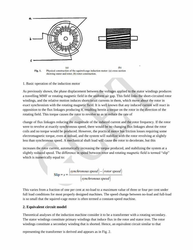
1. Basic operation of the induction motor
As previously shown, the phase displacement between the voltages applied to the stator windings produces
a travelling MMF or rotating magnetic field in the uniform air gap. This field links the short-circuited rotor
windings, and the relative motion induces shortcircuit currents in them, which move about the rotor in
exact synchronism with the rotating magnetic field. It is well known that any induced current will react in
opposition to the flux linkages producing it, resulting herein a torque on the rotor in the direction of the
rotating field. This torque causes the rotor to revolve so as to reduce the rate of
change of flux linkages reducing the magnitude of the induced current and the rotor frequency. If the rotor
were to revolve at exactly synchronous speed, there would be no changing flux linkages about the rotor
coils and no torque would be produced. However, the practical motor has friction losses requiring some
electromagnetic torque, even at noload, and the system will stabilize with the rotor revolving at slightly
less than synchronous speed. A mechanical shaft load will cause the rotor to decelerate, but this
increases the rotor current, automatically increasing the torque produced, and stabilizing the system at a
slightly reduced speed. The difference in speed between rotor and rotating magnetic field is termed “slip”
which is numerically equal to:
This varies from a fraction of one per cent at no-load to a maximum value of three or four per cent under
full load conditions for most properly designed machines. The speed change between no-load and full-load
is so small that the squirrel-cage motor is often termed a constant-speed machine.
2. Equivalent circuit model
Theoretical analyses of the induction machine consider it to be a transformer with a rotating secondary.
The stator windings constitute primary windings that induce flux in the rotor and stator iron. The rotor
windings constitute a secondary winding that is shorted. Hence, an equivalent circuit similar to that
representing the transformer is derived and appears as in Fig. 2.
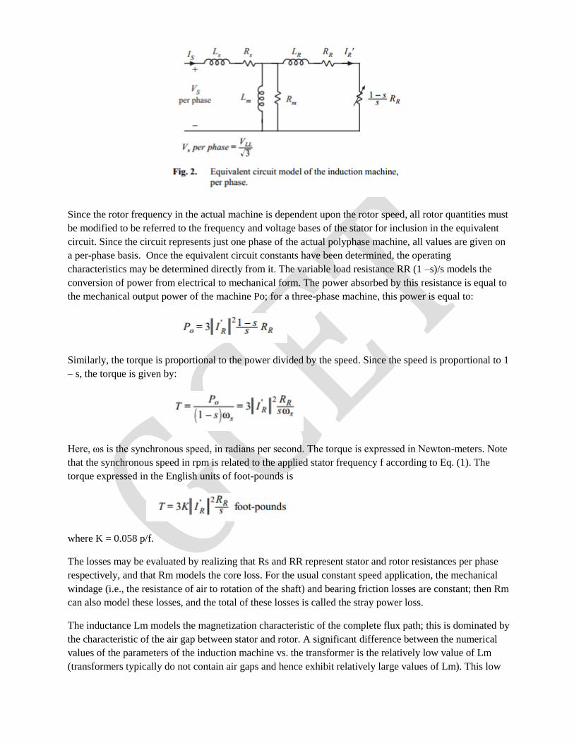
Since the rotor frequency in the actual machine is dependent upon the rotor speed, all rotor quantities must
be modified to be referred to the frequency and voltage bases of the stator for inclusion in the equivalent
circuit. Since the circuit represents just one phase of the actual polyphase machine, all values are given on
a per-phase basis. Once the equivalent circuit constants have been determined, the operating
characteristics may be determined directly from it. The variable load resistance RR (1 –s)/s models the
conversion of power from electrical to mechanical form. The power absorbed by this resistance is equal to
the mechanical output power of the machine Po; for a three-phase machine, this power is equal to:
Similarly, the torque is proportional to the power divided by the speed. Since the speed is proportional to 1
– s, the torque is given by:
Here, ωs is the synchronous speed, in radians per second. The torque is expressed in Newton-meters. Note
that the synchronous speed in rpm is related to the applied stator frequency f according to Eq. (1). The
torque expressed in the English units of foot-pounds is
where K = 0.058 p/f.
The losses may be evaluated by realizing that Rs and RR represent stator and rotor resistances per phase
respectively, and that Rm models the core loss. For the usual constant speed application, the mechanical
windage (i.e., the resistance of air to rotation of the shaft) and bearing friction losses are constant; then Rm
can also model these losses, and the total of these losses is called the stray power loss.
The inductance Lm models the magnetization characteristic of the complete flux path; this is dominated by
the characteristic of the air gap between stator and rotor. A significant difference between the numerical
values of the parameters of the induction machine vs. the transformer is the relatively low value of Lm
(transformers typically do not contain air gaps and hence exhibit relatively large values of Lm). This low
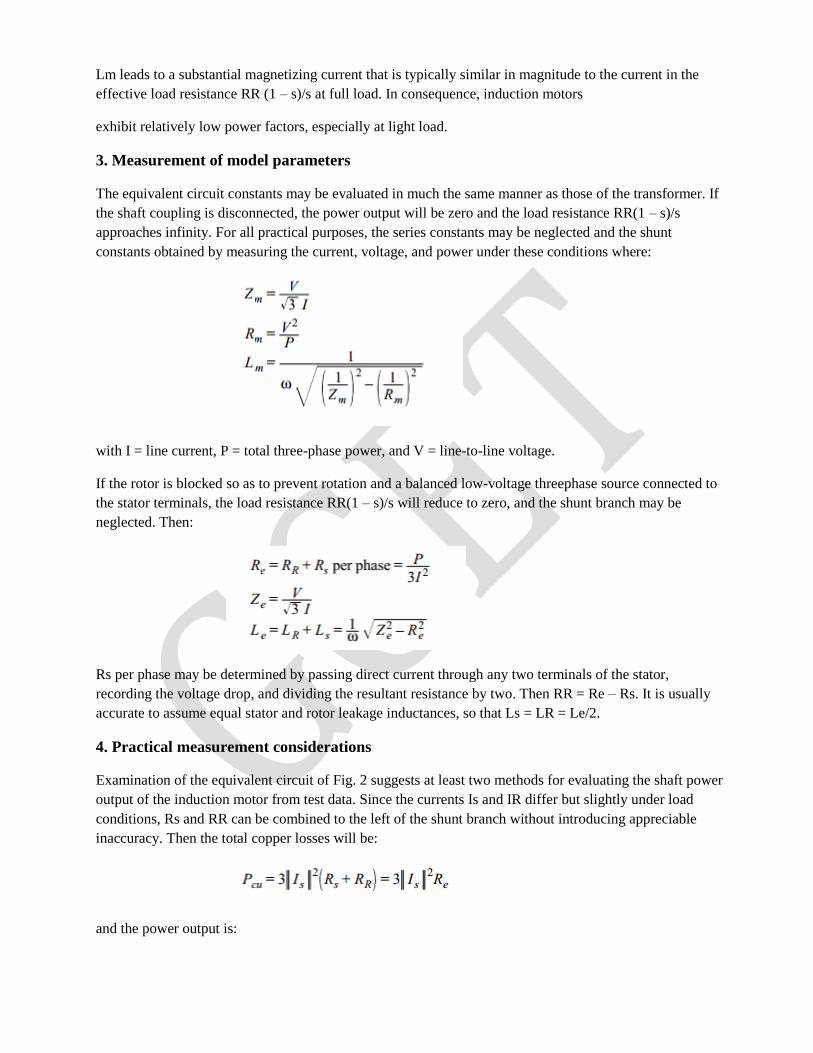
Lm leads to a substantial magnetizing current that is typically similar in magnitude to the current in the
effective load resistance RR (1 – s)/s at full load. In consequence, induction motors
exhibit relatively low power factors, especially at light load.
3. Measurement of model parameters
The equivalent circuit constants may be evaluated in much the same manner as those of the transformer. If
the shaft coupling is disconnected, the power output will be zero and the load resistance RR(1 – s)/s
approaches infinity. For all practical purposes, the series constants may be neglected and the shunt
constants obtained by measuring the current, voltage, and power under these conditions where:
with I = line current, P = total three-phase power, and V = line-to-line voltage.
If the rotor is blocked so as to prevent rotation and a balanced low-voltage threephase source connected to
the stator terminals, the load resistance RR(1 – s)/s will reduce to zero, and the shunt branch may be
neglected. Then:
Rs per phase may be determined by passing direct current through any two terminals of the stator,
recording the voltage drop, and dividing the resultant resistance by two. Then RR = Re – Rs. It is usually
accurate to assume equal stator and rotor leakage inductances, so that Ls = LR = Le/2.
4. Practical measurement considerations
Examination of the equivalent circuit of Fig. 2 suggests at least two methods for evaluating the shaft power
output of the induction motor from test data. Since the currents Is and IR differ but slightly under load
conditions, Rs and RR can be combined to the left of the shunt branch without introducing appreciable
inaccuracy. Then the total copper losses will be:
and the power output is:
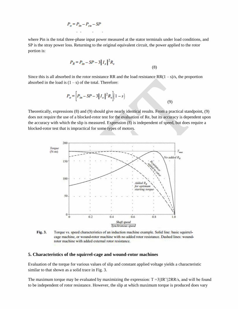
where Pin is the total three-phase input power measured at the stator terminals under load conditions, and
SP is the stray power loss. Returning to the original equivalent circuit, the power applied to the rotor
portion is:
(8)
Since this is all absorbed in the rotor resistance RR and the load resistance RR(1 – s)/s, the proportion
absorbed in the load is (1 – s) of the total. Therefore:
(9)
Theoretically, expressions (8) and (9) should give nearly identical results. From a practical standpoint, (9)
does not require the use of a blocked-rotor test for the evaluation of Re, but its accuracy is dependent upon
the accuracy with which the slip is measured. Expression (8) is independent of speed, but does require a
blocked-rotor test that is impractical for some types of motors.
5. Characteristics of the squirrel-cage and wound-rotor machines
Evaluation of the torque for various values of slip and constant applied voltage yields a characteristic
similar to that shown as a solid trace in Fig. 3.
The maximum torque may be evaluated by maximizing the expression: T =3||IR’||2RR/s, and will be found
to be independent of rotor resistance. However, the slip at which maximum torque is produced does vary
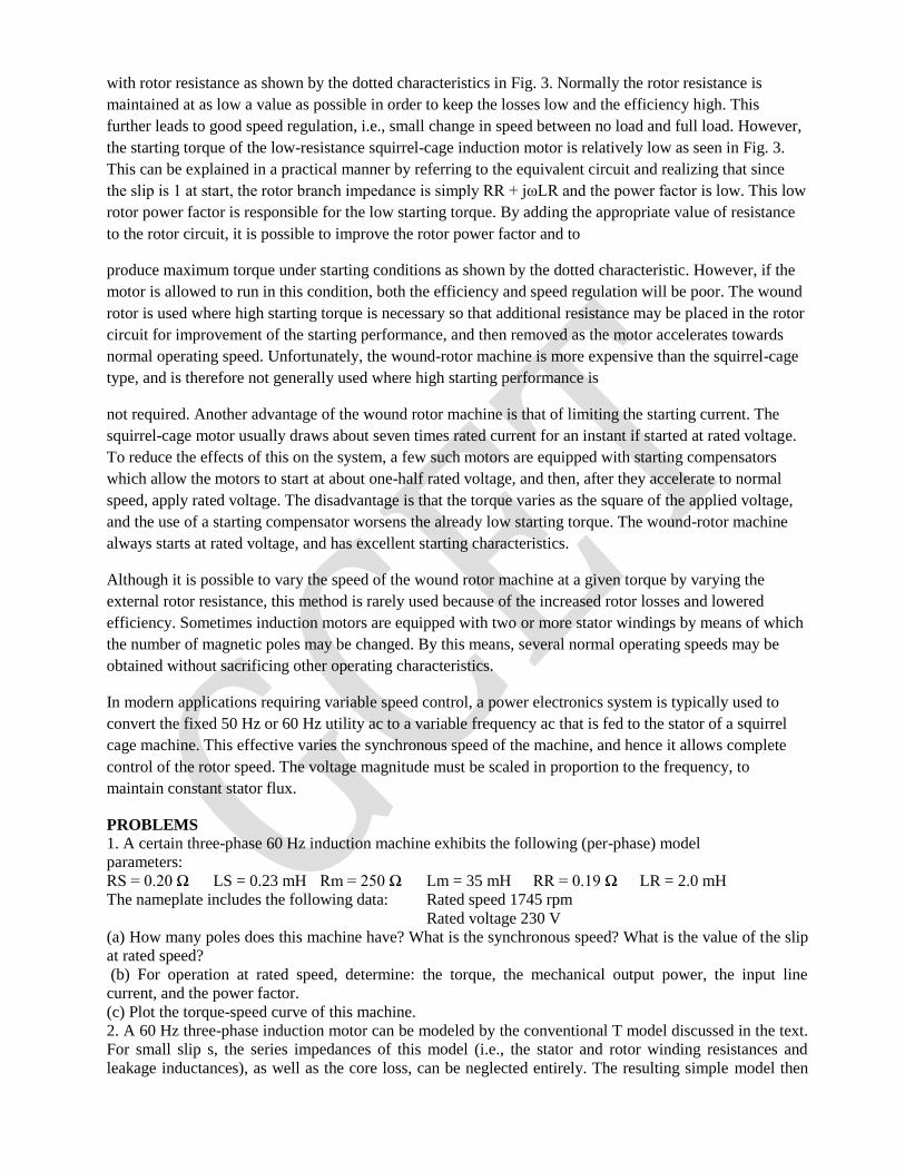
with rotor resistance as shown by the dotted characteristics in Fig. 3. Normally the rotor resistance is
maintained at as low a value as possible in order to keep the losses low and the efficiency high. This
further leads to good speed regulation, i.e., small change in speed between no load and full load. However,
the starting torque of the low-resistance squirrel-cage induction motor is relatively low as seen in Fig. 3.
This can be explained in a practical manner by referring to the equivalent circuit and realizing that since
the slip is 1 at start, the rotor branch impedance is simply RR + jωLR and the power factor is low. This low
rotor power factor is responsible for the low starting torque. By adding the appropriate value of resistance
to the rotor circuit, it is possible to improve the rotor power factor and to
produce maximum torque under starting conditions as shown by the dotted characteristic. However, if the
motor is allowed to run in this condition, both the efficiency and speed regulation will be poor. The wound
rotor is used where high starting torque is necessary so that additional resistance may be placed in the rotor
circuit for improvement of the starting performance, and then removed as the motor accelerates towards
normal operating speed. Unfortunately, the wound-rotor machine is more expensive than the squirrel-cage
type, and is therefore not generally used where high starting performance is
not required. Another advantage of the wound rotor machine is that of limiting the starting current. The
squirrel-cage motor usually draws about seven times rated current for an instant if started at rated voltage.
To reduce the effects of this on the system, a few such motors are equipped with starting compensators
which allow the motors to start at about one-half rated voltage, and then, after they accelerate to normal
speed, apply rated voltage. The disadvantage is that the torque varies as the square of the applied voltage,
and the use of a starting compensator worsens the already low starting torque. The wound-rotor machine
always starts at rated voltage, and has excellent starting characteristics.
Although it is possible to vary the speed of the wound rotor machine at a given torque by varying the
external rotor resistance, this method is rarely used because of the increased rotor losses and lowered
efficiency. Sometimes induction motors are equipped with two or more stator windings by means of which
the number of magnetic poles may be changed. By this means, several normal operating speeds may be
obtained without sacrificing other operating characteristics.
In modern applications requiring variable speed control, a power electronics system is typically used to
convert the fixed 50 Hz or 60 Hz utility ac to a variable frequency ac that is fed to the stator of a squirrel
cage machine. This effective varies the synchronous speed of the machine, and hence it allows complete
control of the rotor speed. The voltage magnitude must be scaled in proportion to the frequency, to
maintain constant stator flux.
PROBLEMS
1. A certain three-phase 60 Hz induction machine exhibits the following (per-phase) model
parameters:
RS = 0.20 Ω LS = 0.23 mH Rm = 250 Ω Lm = 35 mH RR = 0.19 Ω LR = 2.0 mH
The nameplate includes the following data: Rated speed 1745 rpm
Rated voltage 230 V
(a) How many poles does this machine have? What is the synchronous speed? What is the value of the slip
at rated speed?
(b) For operation at rated speed, determine: the torque, the mechanical output power, the input line
current, and the power factor.
(c) Plot the torque-speed curve of this machine.
2. A 60 Hz three-phase induction motor can be modeled by the conventional T model discussed in the text.
For small slip s, the series impedances of this model (i.e., the stator and rotor winding resistances and
leakage inductances), as well as the core loss, can be neglected entirely. The resulting simple model then
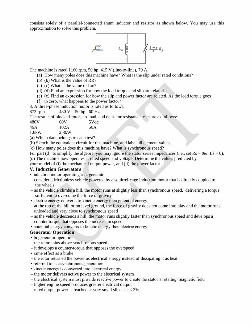
consists solely of a parallel-connected shunt inductor and resistor as shown below. You may use this
approximation to solve this problem.
The machine is rated 1160 rpm, 50 hp, 415 V (line-to-line), 70 A.
(a) How many poles does this machine have? What is the slip under rated conditions?
(b) (b) What is the value of RR?
(c) (c) What is the value of Lm?
(d) (d) Find an expression for how the load torque and slip are related.
(e) (e) Find an expression for how the slip and power factor are related. As the load torque goes
(f) to zero, what happens to the power factor?
3. A three-phase induction motor is rated as follows:
873 rpm 480 V 50 hp 60 Hz
The results of blocked-rotor, no-load, and dc stator resistance tests are as follows:
480V 60V 5Vdc
46A 102A 50A
1.6kW 2.8kW
(a) Which data belongs to each test?
(b) Sketch the equivalent circuit for this machine, and label all element values.
(c) How many poles does this machine have? What is synchronous speed?
For part (d), to simplify the algebra, you may ignore the stator series impedances (i.e., set Rs = 0& Ls = 0).
(d) The machine now operates at rated speed and voltage. Determine the values predicted by
your model of (i) the mechanical output power, and (ii) the power factor.
V. Induction Generators • Induction motor operating as a generator
– consider a frictionless vehicle powered by a squirrel-cage induction motor that is directly coupled to
the wheels
– as the vehicle climbs a hill, the motor runs at slightly less than synchronous speed, delivering a torque
sufficient to overcome the force of gravity
• electric energy converts to kinetic energy then potential energy
– at the top of the hill or on level ground, the force of gravity does not come into play and the motor runs
unloaded and very close to synchronous speed
– as the vehicle descends a hill, the motor runs slightly faster than synchronous speed and develops a
counter torque that opposes the increase in speed
• potential energy converts to kinetic energy then electric energy
Generator Operation • In generator operation
– the rotor spins above synchronous speed
– it develops a counter-torque that opposes the overspeed
• same effect as a brake
– the rotor returned the power as electrical energy instead of dissipating it as heat
• referred to as asynchronous generation
• kinetic energy is converted into electrical energy
– the motor delivers active power to the electrical system
– the electrical system must provide reactive power to create the stator’s rotating magnetic field
– higher engine speed produces greater electrical output
– rated output power is reached at very small slips, |s | < 3%
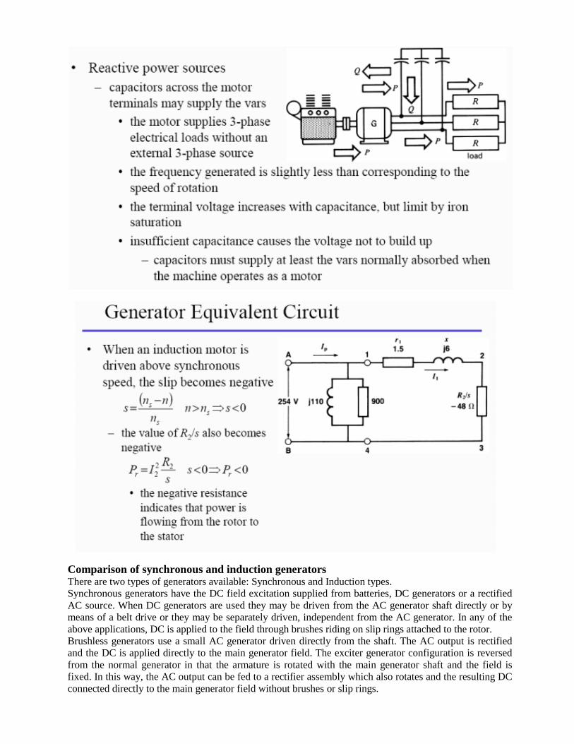
Comparison of synchronous and induction generators There are two types of generators available: Synchronous and Induction types.
Synchronous generators have the DC field excitation supplied from batteries, DC generators or a rectified
AC source. When DC generators are used they may be driven from the AC generator shaft directly or by
means of a belt drive or they may be separately driven, independent from the AC generator. In any of the
above applications, DC is applied to the field through brushes riding on slip rings attached to the rotor.
Brushless generators use a small AC generator driven directly from the shaft. The AC output is rectified
and the DC is applied directly to the main generator field. The exciter generator configuration is reversed
from the normal generator in that the armature is rotated with the main generator shaft and the field is
fixed. In this way, the AC output can be fed to a rectifier assembly which also rotates and the resulting DC
connected directly to the main generator field without brushes or slip rings.
Synchronous generators are rated in accordance with NEMA Standards on a continuous duty basis. The
rating is expressed in KVA available at the terminals at 0.80 power factor. The corresponding KW should
also be stated. For example, a 400 KW generator would be rated 500 KV A at 0.80 power factor.
An induction generator receives its excitation (magnetizing current) from the system to which it is
connected. It consumes rather than supplies reactive power (KVAR) and supplies only real power (KW) to
the system. The KVAR required by the induction generator plus the KVAR requirements of all other loads
on the system must be supplied from synchronous generators or static capacitors on the system.
When a squirrel cage induction motor is energized from a power system and is mechanically driven above
its synchronous speed it will deliver power to the system. Operating as a generator at a given percentage
slip above synchronous speed, the torque, current, efficiency and power factor will not differ greatly from
that when operating as a motor. The same slip below synchronous speed, the shaft torque and electric
power flow is reversed. For example, a 3600 RPM squirrel cage induction motor which delivers full load
output at 3550 RPM as a motor will deliver full rated power as a generator at 3650 RPM If the haJf-load
motor speed is 3570 RPM, the output as a generator will be one-half of rated value when driven at 3630
RPM, etc. Since the induction generator is actually an induction motor being driven by a prime mover, it
has severaI advantages.
1. It is less expensive and more readily available than a synchronous generator.
2. It does not require a DC field excitation voltage.
3. It automatically synchronizes with the power system, so its controls are simpler and less expensive.
The principal disadvantages of an induction generator are listed.
1. It is not suitable for separate, isolated operation
2. It consumes rather than supplies magnetizing KVAR
3. It cannot contribute to the maintenance of system voltage levels (this is left entirely to thesynchronous
generators or capacitors)
4. In general it has a lower efficiency.
Induction Generator Application • With energy costs so high, energy recovery became an important part of the economics of most industrial
processes. The induction generator is ideal for such applications because it requires very little in the way of
control system or maintenance.
• Because of their simplicity and small size per kilowatt of output power, induction generators are also
favored very strongly for small windmills. Many commercial windmills are designed to operate in parallel
with large power systems, supplying a fraction of the customer’s total power needs. In such operation, the
power system can be relied on for voltage & frequency control, and static capacitors can be used for
power-factor correction.
15.Additional / Missing Topics:
16. University Previous Question Papers:
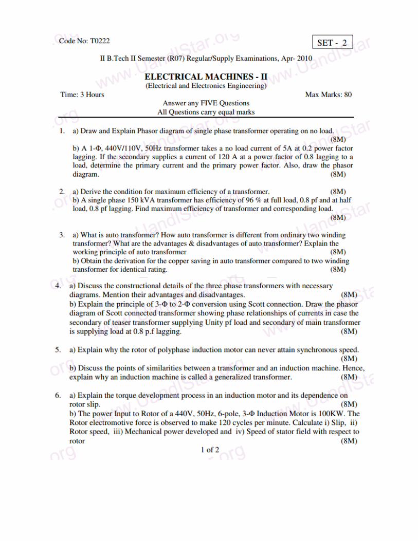
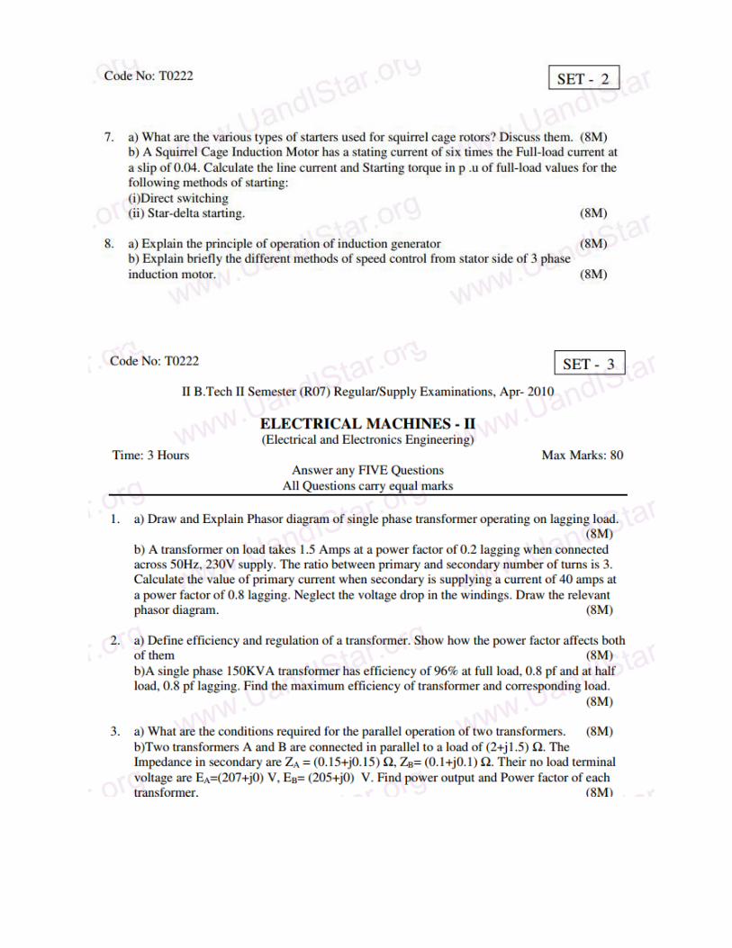
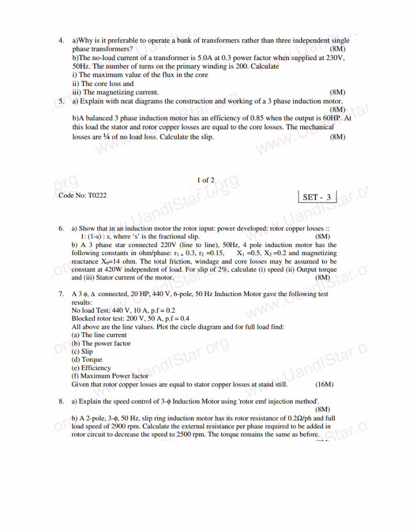
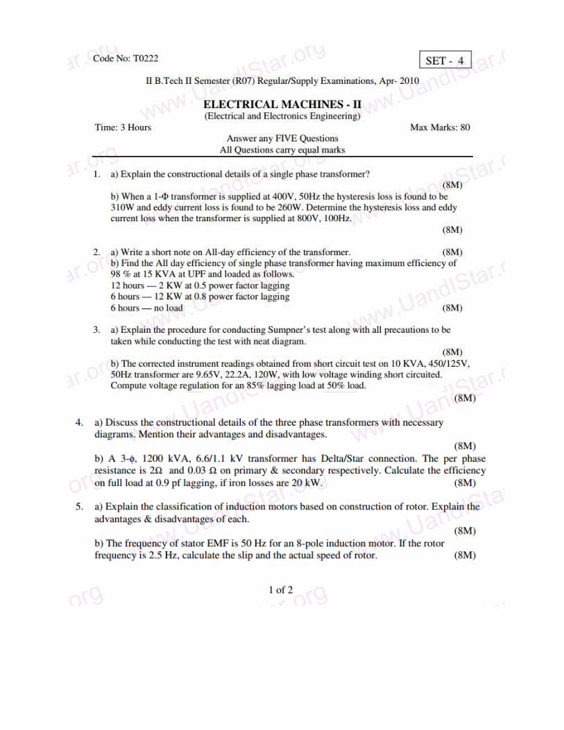
17.Question Bank:
UNIT-I
Objective Questions
1. A transformer transforms: ( )
a) frequency
b) only voltage
c) only current
d) both voltage and current
2. An ideal transformer is defined as one ( )
a) whose windings have no resistance
b) whose core has no losses
c) whose core has infinite permeability
d) which has all the above properties
3. A transformer having 1000 primary turns is connected to a 250 v ac supply. For a secondary voltage
of 400 V, the number of secondary turns should be ___________
4. A step up transformer increases ( )
a) voltage
b) current
c) power
d) frequency
5) . A transformer will work on ____________
(a)a.c only (b)d.c only (c)a.c as well as d.c (d)none of the above
6) The primary and secondary of a transformer are ___________ Coupled
(A) Electrically (b) magnetically (c) electrically magnetically
(d) None of the above
7) A transformer is an efficient device because it ___________
(a)is a static device (b)uses inductive coupling (c)Uses capacitive coupling
(d) Uses electric coupling
8) The voltage per turn of the primary of transformer is_____The voltage for turn of the secondary
a) more than b) less than c) the same as d) none of the above
9)How is magnetic leakage reduced to a minimum in commercial transforemer---------
10)Mention the factors on which hysterisis loss depends
11)________________ is not a basic element of a transformer
12)The main purpose of using core type of transforemer is_____________
13)In ideal transformer ________________
14)The main purpose of using core in a transformer is to___________
15)Transformer core is laminated inorder to reduce______________
16)A step up transformer increases___________________
17)The primary and secondary windings of an ordinary 2-winding transformer are
always______________________
18)In a transformer, the leakage flux of each winding is propotional to the current in that winding
because___________
19)In relation to transformer,the ratio 20:1 indicates that________________
20)The primary and secondary induced e.m.f’s E1 and E2 in a two winding transformer are
always___________-
21.The equivalent resistance of the primary of a transformer having k=N1/N2=5 and r=0.1 , when
referred to secondary, becomes ______ .
22.A transformer can have negative voltage regulation when its load power factor is ---
23)Transformers are rated in KVA instead of KW because _______
24)How eddy current loss can be minimized in an iron core?
25)How does a change in frequency affect the operation of a given transformer?
26)Which of the following is not a basic element of a transformer ( )
a) Core b)primary winding c) secondary winding d) shaft
27)When a 400 Hz transformer is operated at 50 Hz, its KVA rating is( )
a)reduced to 1/8 approximately
b)increased to 8 times approximately
c)unaffected d)increased 64 times approximately
28)The power efficiency of a given transformer is maximum ( )
a)at no load b)always at 50% rated KVA load c)always at its rated KVA load
d)when its copper loss equals iron loss.
29)The _______ loss of a transformer has a significant influence on its all day efficiency.
30)The maximum efficiency of a 100 KVA transformer having an iron loss of 900 KW and full load
copper loss of 1600 W occurs at ________ KVA
31)If copper loss of a transformer at 7/8th full load is 4900 W, then its
32)At relatively light loads, transformer efficiency is low, because
33)The iron core is used to _________of the transformer
a) increase the weight b) provide tight magnetic coupling) reduce core losses
d) none of the above
34) The maximum flux produced in the core of a transformer is__________
a) Directly proportional to supply frequency b) inversely proportional to supply frequency
c) Inversely proportional to primary voltage d) none of the above
35) When the primary of a transformer is connected to a d.c supply____________
(a) Primary draws small current (b) primary leakage reactance is increased (c) core losses are increased
(d) primary may burn out
36)An ideal transformer is one which__________
(a)has no losses and leakage reactance (b)does not work (c)as same number of primary and secondary
turns (d) none of the above
37) A transformer has an efficiency of 80% and works at 100V,4KW if the secondary voltage 240V,find
the primary current
(a)40A (b)30A (c)20A (d)10A
38) In the above question, what is the secondary current?
(a)12.5A (b)9.42A (c)11.56A (d)13.33A
39)A 2000/200V,20KVA ideal transformer has 66 turns in the secondary the no.of primary turns
is_____________
(a)440 (b)660 (c)550 (d)330
40)the no-load ratio of a 50Hz single phase transformer is 6000/250V the maximum flux in the core is
0.06Wb. What is the no.of primary turns
(a)450 (b)900 (c)350 (d)210
41)In the above question what is the no. of secondary turns?
(a)38 (b)19 (c)76 (d)104
42) A 20 turn iron cored indicator is connected to a 100V, 58Hz source. The maximum flux density in
the core is 1Wb/m^2. the cross sectional area of the core is_________
(a)0.152m^2(b)0.345 m^2(c)0.056 m^2(d)0.0225 m2
43) Calculate the core area required for a 1600 kVA, 6600/440V, 50Hz single phase core type power
transformer. Assume a maximum flux density of 1.2 WB/m^2 and induced voltage per turn of 30 V.
(a) 975 cm2 (b) 1100 cm2 (c) 1125 cm2 (d) 1224 cm2
UNIT – II
Objective Questions
1. The reason why open circuit test is performed on the low voltage winding of the transformer is
_______________
2. No-load test on a transformer is carried out to determine ( )
e) the copper loss
f) the voltage regulation of transformer
g) magnetizing current and no-load loss
h) efficiency of the transformer
3. The purpose of performing open-circuit test on a transformer is to measure its __________
4. During the short-circuit test on a transformer, its iron losses are negligible because __________
5. In relation to a transformer, the transformation ratio 20:1 indicates that _______
6. In performing short circuit test of a transformer ( )
a) The high voltage side is usually short-circuited.
b) The low voltage side is usually short-circuited
c) Either side may be short-circuited with no particular preference
d) Neither the high voltage side nor the low voltage side is shorted.
7. For a given magnitude of load current, a transformer has the maximum value for its regulation if the
load power factor angle equals to ( )
a) zero
b) 90 lag
c) 90 lead
d) Impedance angle of transformer
8. Two transformers A and B having equal output voltage ratios but unequal percentage impedances of
4% and 2% respectively are operating in parallel with load equal to the sum of ratings of A and B.
Transformer B will be running over-load by _______ %.
9. The essential conditions for effective parallel operation of two 1 transformers ( )
a) same KVA rating
b) same primary and secondary voltage ratings
c) same percentage impedance
d) terminals of same polarity to be connected together while paralleling
10. The saving in copper achieved by converting a two-winding transformer into an auto-transformer
is determined by _______
11. If the full-load iron loss of a transformer is 100 W, what will be its iron loss at half-load.
12. The open-circuit test on a transformer is performed with ( )
a) rated transformer voltage
b) rated transformer current
c) direct current
d) high frequency supplier
13. A transformer has N1 and N2 turns in primary and secondary windings respectively. Its secondary
winding reactance of X2, when referred to primary is ( )
a) (N2/N1)2 X2
b) (N2/N1) X2
c) (N1/N2)2 X2
d) (N1/N2) X2
14.Hysteresis loss in a transformer depends on ( )
e) applied primary voltage alone
f) frequency of the primary voltage alone.
g) Both primary voltage and its frequency
h) Neither primary voltage nor its frequency.
15. The efficiency of a transformer at full load 0.8 pf lag is 90%, then its efficiency at full-load 0.8pf lead
is ( )
a. less than 90%
b. More than 90%
c. 90%
d. Not deducible from given data
16. The value of flux determining the rms value of the induced emf in a transformer is ( )
a. its rms value
b. its average value
c. its instantaneous value
d. its peak value
17. The no-load current in a transformer lags the applied voltage by( )
a) 90 b) about 75 c) 0 d) about 115
18. The power factor of a transformer on no-load is poor due to ( )
a) low ratio of magnetizing reactance to ‘Core loss’ resistance in the transformer
equivalent to circuit
b) high ratio of magnetizing reactance to ‘Core Loss; resistance in the transformer equivalent
circuit.
c) Low primary winding resistance
d) Low no-load current
19. A 1 transformer has a turns ratio of 4:1. If the secondary winding has a resistance of 1,
the secondary resistance referred to the primary will be: ( )
a) 16 b) 4 c) 0.25 d) 0.06
20. The core of a transformer is made of: ( )
a) annealed copper
b) silicon steel) seas oned wood 21. A T-T transformer cannot be paralleled with __________ transformer.
22. A balanced load of 0.866pf is supplied by a V-V connected bank of transformer, then the average pf
of the V-bank is _________
23. When a V-V connected bank of transformer is converted into a - system, by the addition of
an additional single-phase transformer, then the increase in capacity of the system is _________ %.
24. Which of the following transformer connections is best suited for 3 , 4 wire service?( )
a. -
b. Y – Y
c. – Y
d. Y –
25. In a 3 induction motor, relative speed of stator flux with respect to ________________ is
zero.
26. When one transformer of a bank of - connected transformers is taken out of service, the
capacity in KVA of the resulting V-V system is ____________ percent of the rating of the - bank.
27. The biggest advantage of a T-T connection over the V-V connection for 3 power
transformation is that it provides __________
28.In a three phase Y – Y transformer connection neutral is fundamental to the
29)When V-V system is converted to - system,increase in capacity of the system
is_______________percent
30)If a load P.F is 0.8666,then the average p.f of V_V bank_____________
31)A T-T connection has higher ratio of utilization that a V-V bank is______
32)The biggest advantage of T-T connection over the V-V connection for 3-phase power transformation
is thst it provides _________________
33)For supplying a balanced 3-phase load of 40-KVA,rating of each transformer in V-V bank should be
nearly___KVA
34)Instrument transformers are used on a.c circuits for extending the range of ----
35) The percentage(%) voltage regulation of the Transformer is given by _______
a) 2 2
2
E V
V
b) 2 2
2
E V
E
c) 2 2
2
V E x 100
E
d) 2 2
2
E V x 100
E
36. The full load rating of a Transformer is 90 kW at power factor of 0.9 its KVA rating would be
_____
UNIT-III
Objective Questions
1) Fundamental slip of an induction motor is the ratio of ( )
a. rotor copper loss / rotor input
b. stator copper loss / stator input
c. stator copper loss / rotor input
d. rotor copper loss / rotor output
2) An induction motor works with ( )
e. DC only b) AC only c) either AC or DC d) AC superimposed on DC
3) When an induction motor is standstill, the slip is ( )
f. 0 b) 1 c) d) None
4) The synchronous speed of a given induction motor can be increased by ( )
g. reducing its mechanical friction
h. increasing the supply voltage
i. reconnecting it for a larger number of poles
j. Increasing the frequency of supply.
5) An induction motor has a synchronous speed of 1500 rpm, what is the value of slip, if
it is running at a speed of 1440 rpm. ( )
a) 96% b) 60% c) 4% d) -4%
6)A 4 pole, 50 Hz, induction motor runs at a speed of 1440 rpm. The frequency of rotor currents is
a) 50 Hz b) 48 Hz c) 4 Hz d) 2 Hz
7) 3 Induction motors are widely used in industries because
a) They provide excellent starting torque
b) Their speed can be controlled easily over a wide range
c) They are less expensive and rugged in construction
d) They have good operating power factors.
8) Mention different 3 transformer connections?
9). For 3 induction motors, synchronous speed (Ns), stator frequency (f) and number of Poles (p) are
related as
a) Ns=P/120f b) f=PNs/120 C) f=120Ns/P d) Ns=120P/f
10) An induction motor under full-load condition has a fractional slip of about: ( )
a) 0.03 b) 0.1 c) 0.3 d) 0
11) A 50 Hz, 3 induction motor operative under full-load has a speed of 720 rpm. The number of poles
of motor is equal to ( )
a) 2 b) 4 c) 8 d) 16
12)The power supply in a 3 induction motor is connected to ( )
a) The stator windings only
b) The rotor windings only
c) Both stator and rotor windings
d) the Stator winding, while a DC supply is connected to the rotor winding.
13) The rotor of a 3 induction motor cannot run at synchronous speed, because:( )
a) it would violate Lenz’s Law
b) the rotor copper loss prevents it to do so.
c) the developed torque would then become zero
d) the mechanical structure of the motor breaks down at synchronous speed.
14 The slip on nduction motor normally does not depend upon
a)Rotor speed GATE-2012
b)Synchronous speed
c)Shaft torque
d)cross-loss component
15) A three phse 440V, 50HZ squirrel cage induction motor is running at a slip of 5%. The speed of stator
magnetic field to the rotor magnetic field and speed of the rotor to the statorrotor magnetic field is
1000RPM -50RPM
16. Define crawling in a 3 phase induction motor?
17. Define cogging in a 3 phase induction motor?
18. Sketch the equivalent circuit of a 3 phase induction motor?
19. At slip equal to infinity the torque of a 3 phase induction motor is ( )
a) negative b) 0 c) very small d) high
20. In a 3 phase 50 Hz induction motor under normal operation the rotor core losses are ( )
a) higher than stator core losses
b) smaller than stator core losses
c) equal to stator core losses
d) zero
21. The squirrel cage rotor of 4 pole 3 phase induction motor can be used with a stator wound for the
following number of poles ( )
a)only 4 b) with 4 or 8 poles
c)only an integral multiple of 4 d)any even number of the poles
22. A 3 phase 50 Hz ,4 pole squirrel cage induction motor has its stator rewound for 6 phases with out
any alteration in the rotor. The stator would now run at a speed of about ( )
a)1000 rpm b) 1500 rpm c)3000 rpm d)0 rpm
23. In a 3 phase induction motor the maximum torque ( )
a) is proportional to (r2)2
b) is proportional to r2
c) is proportional to (r2)1/2
d) does not depend upon r2
24. In a 3 phase wound rotor induction motor a 3 phase balanced delta supply is given to the rotor and
stator winding is short circuited .Then the motor would ( )
a) not run
b) run in the direction of the rotating field set up by the stator
c) run in the opposite direction of the rotating field set up by the stator
d) continue to run in either direction if given an external start
25. The rotor of a synchronous motor run at synchronous speed if did so then ( )
1.Rotor emf would be zero
2.rotor current would be zero
3.rotor torque would be zero
26. choose the correct response from the following alternatives
a) assertion 1 is only is correct
b) assertion 2 is only is correct
c) assertion 3 is only is correct
d) all the three assertions are correct
27. Give the expression for the torque developed by a 3 phase induction motor in terms of its rotor
circuit parameters slip and rotor emf per phase at stand still
28. If the rotor circuit resistance of a 3 phase induction motor is increased above its normal value the n
the starting torque and the maximum torque developed are
29. A 3 phase 4 pole induction motor develops a torque of 200 Nm.. If the supply voltage is reduced to
200 V, then the torque developed will be
30. Sketch the torque slip characteristics of a 3 phase induction motor
31. If the stator voltage and frequency of an induction motor are reduced proportionately its ( )
a) Locked rotor current is reduced
b) Torque developed is increased
c) Magnetizing current is decreased
d) Both a& b
32. If the maximum torque of an induction motor is 200 Kg-m at a slip of 12%, the torque at 6% slip
would roughly be
33. A 3 phase 6 pole, 50 Hz induction motor has a full load speed of 950 rpm .At half load its speed
approximately be
34. A 3 phase 6 pole ,50 Hz induction motor has a full load speed of 950 rpm , and has rotor copper
loss of 5 KW. Its rotor input is
35. The power factor of a squirrel cage induction motor is low at ( )
k. light loads only
l. heavy loads only
m. both heavy and light loads
n. rated load only
36. A 3 phase 4 pole ,50 Hz induction motor has a full load speed of 1440 rpm .The rotating magnetic
field produced by the rotor currents rotates at a speed of _______________ with respect to rotor.
UNIT - IV
Objective Questions
1. Direct on line starting of a large induction motor should be avoided because ( )
a) the starting torque is very high
b) the rotor may run in reverse
c) the motor may pick up dangerously high speed
d) the motor takes about 5-7 times its full load current
2. An induction motor cannot run at synchronous speed give reasons?
3. Give the indications of winding failure in an induction motor
4. What factors determine the direction of rotation of an 3 phase induction motor
5. How does the slip of an induction motor vary with load?
6. In the circle diagram of a 3 phase induction motor the diameter of the circle is( )
a) Rotor current
b) Exciting current
c) Total stator current
d) Total current referred to stator
7. In the circle diagram of an induction motor, point of maximum input lies on the tangent to the
circle drawn parallel to
8. An induction motor has short circuit current 7 times the full load current and a full load slip of 4%.
Its on line starting torque is _______________ Times the full load torque
9. For the purpose of starting of an induction motor a star –delta switch which is equivalent to an auto
transformer starter of ratio________________ percent
10. If the starter voltage of a squirrel cage induction motor is reduced to 50 % of its rated value the
torque developed is reduced to _____________ percent of its full load value
11. In a squirrel cage induction motor the starting torque with autotransformer starter of ratio 1: a is
_________ times the starting torque with direct switching.
12. A six pole 3 induction motor taking 25KW from a 50Hz supply is cumulatively cascaded to a 4
pole motor. Neglecting the losses, speed of the 4 pole motor would be __________________rpm and its
output would be _________ KW.
13. How can induction motors be protected against single phasing?
14. What does phase splitter mean?
15. Describe the principle of operation of a Schrage motor?
16. A wound rotor induction motor can be reversed by transposing any two leads from the slip rings
[T/F]
17. What is the standard direction of rotation of induction motor?
18. Pick out the wrong statement Blocked rotor test on a three phase induction motor helps to find (
)
a) short circuit current with normal voltage
b) short circuit power factor
c) fixed losses
d) motor resistance as referred to stator
19. If the frequency of 3- phase supply to the stator of a 3-phase induction motor is increased, then
synchronous speed___________
a) is decreased b) is increased
c) Remains un changed d) None of the above
20. The synchronous speed of a 3-phase induction motor having 20-poles and frequency 50Hz is
a) 600rpm b) 100rpm
c) 1200rpm d) 300rpm
21. The relation among synchronous speed (NS) rotor speed (N) and slip(S) is____________
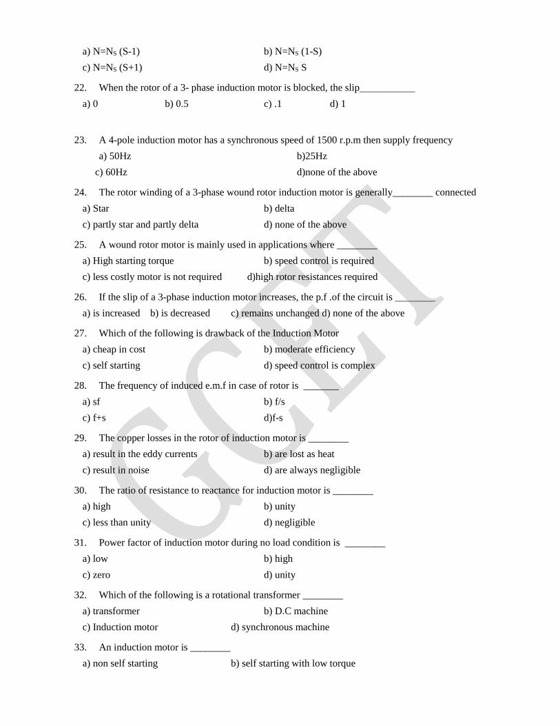
a) N=NS (S-1) b) N=NS (1-S)
c) N=NS (S+1) d) N=NS S
22. When the rotor of a 3- phase induction motor is blocked, the slip___________
a) 0 b) 0.5 c) .1 d) 1
23. A 4-pole induction motor has a synchronous speed of 1500 r.p.m then supply frequency
a) 50Hz b)25Hz
c) 60Hz d)none of the above
24. The rotor winding of a 3-phase wound rotor induction motor is generally________ connected
a) Star b) delta
c) partly star and partly delta d) none of the above
25. A wound rotor motor is mainly used in applications where ________
a) High starting torque b) speed control is required
c) less costly motor is not required d)high rotor resistances required
26. If the slip of a 3-phase induction motor increases, the p.f .of the circuit is ________
a) is increased b) is decreased c) remains unchanged d) none of the above
27. Which of the following is drawback of the Induction Motor
a) cheap in cost b) moderate efficiency
c) self starting d) speed control is complex
28. The frequency of induced e.m.f in case of rotor is _______
a) sf b) f/s
c) f+s d)f-s
29. The copper losses in the rotor of induction motor is ________
a) result in the eddy currents b) are lost as heat
c) result in noise d) are always negligible
30. The ratio of resistance to reactance for induction motor is ________
a) high b) unity
c) less than unity d) negligible
31. Power factor of induction motor during no load condition is ________
a) low b) high
c) zero d) unity
32. Which of the following is a rotational transformer ________
a) transformer b) D.C machine
c) Induction motor d) synchronous machine
33. An induction motor is ________
a) non self starting b) self starting with low torque
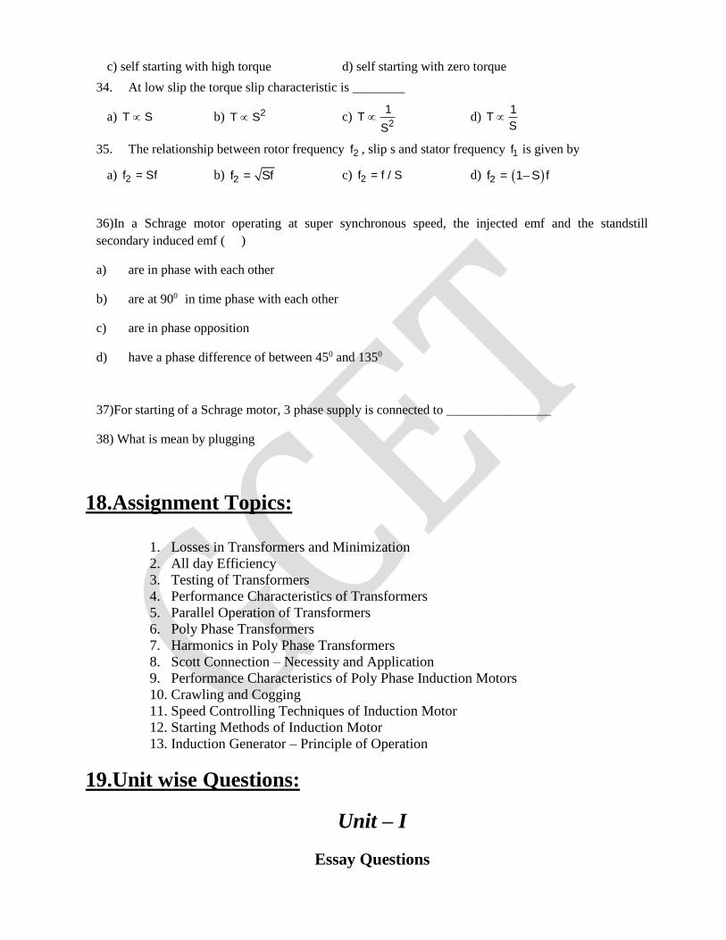
c) self starting with high torque d) self starting with zero torque
34. At low slip the torque slip characteristic is ________
a) T S b) 2T S c) 2
1T
S d)
1T
S
35. The relationship between rotor frequency 2f , slip s and stator frequency 1f is given by
a) 2f = Sf b) 2f = Sf c) 2f = f / S d) 2f = 1 S f
36)In a Schrage motor operating at super synchronous speed, the injected emf and the standstill
secondary induced emf ( )
a) are in phase with each other
b) are at 900 in time phase with each other
c) are in phase opposition
d) have a phase difference of between 450 and 1350
37)For starting of a Schrage motor, 3 phase supply is connected to ________________
38) What is mean by plugging
18.Assignment Topics:
1. Losses in Transformers and Minimization
2. All day Efficiency
3. Testing of Transformers
4. Performance Characteristics of Transformers
5. Parallel Operation of Transformers
6. Poly Phase Transformers
7. Harmonics in Poly Phase Transformers
8. Scott Connection – Necessity and Application
9. Performance Characteristics of Poly Phase Induction Motors
10. Crawling and Cogging
11. Speed Controlling Techniques of Induction Motor
12. Starting Methods of Induction Motor
13. Induction Generator – Principle of Operation
19.Unit wise Questions:
Unit – I
Essay Questions
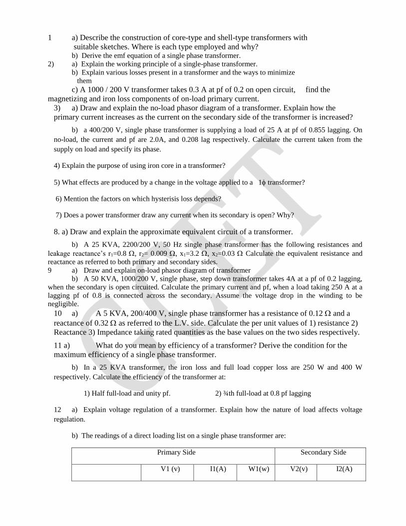
1 a) Describe the construction of core-type and shell-type transformers with
suitable sketches. Where is each type employed and why? b) Derive the emf equation of a single phase transformer.
2) a) Explain the working principle of a single-phase transformer.
b) Explain various losses present in a transformer and the ways to minimize
them
c) A 1000 / 200 V transformer takes 0.3 A at pf of 0.2 on open circuit, find the
magnetizing and iron loss components of on-load primary current.
3) a) Draw and explain the no-load phasor diagram of a transformer. Explain how the
primary current increases as the current on the secondary side of the transformer is increased?
b) a 400/200 V, single phase transformer is supplying a load of 25 A at pf of 0.855 lagging. On
no-load, the current and pf are 2.0A, and 0.208 lag respectively. Calculate the current taken from the
supply on load and specify its phase.
4) Explain the purpose of using iron core in a transformer?
5) What effects are produced by a change in the voltage applied to a 1 transformer?
6) Mention the factors on which hysterisis loss depends?
7) Does a power transformer draw any current when its secondary is open? Why?
8. a) Draw and explain the approximate equivalent circuit of a transformer.
b) A 25 KVA, 2200/200 V, 50 Hz single phase transformer has the following resistances and
leakage reactance’s r1=0.8 , r2= 0.009 , x1=3.2 , x2=0.03 Calculate the equivalent resistance and
reactance as referred to both primary and secondary sides.
9 a) Draw and explain on-load phasor diagram of transformer
b) A 50 KVA, 1000/200 V, single phase, step down transformer takes 4A at a pf of 0.2 lagging,
when the secondary is open circuited. Calculate the primary current and pf, when a load taking 250 A at a
lagging pf of 0.8 is connected across the secondary. Assume the voltage drop in the winding to be
negligible.
10 a) A 5 KVA, 200/400 V, single phase transformer has a resistance of 0.12 and a
reactance of 0.32 as referred to the L.V. side. Calculate the per unit values of 1) resistance 2)
Reactance 3) Impedance taking rated quantities as the base values on the two sides respectively.
11 a) What do you mean by efficiency of a transformer? Derive the condition for the
maximum efficiency of a single phase transformer.
b) In a 25 KVA transformer, the iron loss and full load copper loss are 250 W and 400 W
respectively. Calculate the efficiency of the transformer at:
1) Half full-load and unity pf. 2) ¾th full-load at 0.8 pf lagging
12 a) Explain voltage regulation of a transformer. Explain how the nature of load affects voltage
regulation.
b) The readings of a direct loading list on a single phase transformer are:
Primary Side Secondary Side
V1 (v) I1(A) W1(w) V2(v) I2(A)
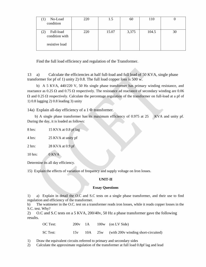
(1) No-Load
condition
220 1.5 60 110 0
(2) Full-load
condition with
resistive load
220 15.07 3,375 104.5 30
Find the full load efficiency and regulation of the Transformer.
13 a) Calculate the efficiencies at half full-load and full load of 50 KVA, single phase
transformer for pf of 1) unity 2) 0.8. The full load copper loss is 500 w.
b) A 5 KVA, 440/220 V, 50 Hz single phase transformer has primary winding resistance, and
reactance as 0.25 and 0.75 respectively. The resistance ad reactance of secondary winding are 0.06
and 0.25 respectively. Calculate the percentage regulation of the transformer on full-load at a pf of
1) 0.8 lagging 2) 0.8 leading 3) unity
14a) Explain all-day efficiency of a 1 transformer.
b) A single phase transformer has its maximum efficiency of 0.975 at 25 KVA and unity pf.
During the day, it is loaded as follows:
8 hrs: 15 KVA at 0.8 pf lag
4 hrs: 25 KVA at unity pf
2 hrs: 28 KVA at 0.9 pf
10 hrs: 0 KVA
Determine its all day efficiency.
15) Explain the effects of variation of frequency and supply voltage on Iron losses.
UNIT-II
Essay Questions
1) a) Explain in detail the O.C and S.C tests on a single phase transformer, and their use to find
regulation and efficiency of the transformer.
b) The wattmeter in the O.C. test on a transformer reads iron losses, while it reads copper losses in the
S.C. test. Why?
2) O.C and S.C tests on a 5 KVA, 200/40v, 50 Hz a phase transformer gave the following
results.
OC Test: 200v 1A 100w (on LV Side)
SC Test: 15v 10A 25w (with 200v winding short-circuited)
1) Draw the equivalent circuits referred to primary and secondary sides
2) Calculate the approximate regulation of the transformer at full load 0.8pf lag and lead
3) a) How can you predetermine efficiency and regulation for a given single phase
transformer at any load without carrying out a load test?
b) How can you predetermine the load at which two losses i.e. iron losses and copper losses are
equal? How can you estimate the efficiency at any load?
c) A 11000/230v, 150 KVA, 1 – phase, 50Hz transformer has a core loss of 1.4 KW and a full
load copper loss of 1.6 KW. Determine
1) The KVA load for maximum efficiency and the value of maximum efficiency at unity pf?
2) The efficiency at half full-load, 0.8pf leading.
4) a) A100KVA, single phase transformer when working at UPF has an efficiency of 90% both at
full load and half load determine the efficiency when it operates at UPF.
b) A 300 KVA single phase transformer is designed to have a resistance of 1.5% and its
maximum efficiency at a load of 173.2KVA. Find its efficiency when supplying full load at 0.8 power
factor lagging at normal voltage and frequency.
5) Describe a test for separation of iron losses in a transformer?
6) a) Describe the conditions required for the parallel operation of two single phase
transformers.
b) Describe the process of load sharing by two single phase transformers, when connected in parallel
with equal voltage ratios and also unequal voltage ratios
7 a) Explain the operation of an auto transformer with a neat sketch and deduce the
saving of copper in auto transformer compared with a 2 winding transformer of the same rating?
b) A 5KVA, 2300/230 V two winding transformer is reconnected as a 2530/2300 V auto
transformer and excited by a 2530V source. The transformer is loaded to the maximum extent that the
rated currents of the windings are not exceeded. Calculate
i) Currents in different sections of the auto transformer
ii) KVA output
iii) VA transferred inductively and conductively from input to output
iv) Saving in copper as compared to a 2530/2300V two winding transformer for same output.
UNIT – III
Essay Questions
1) a) Explain different types of three phase connections.
b) Explain the construction of 3 phase transformer.
2) a) Explain Scott connection of transformer
b) 2 transformers are used in Scott connection to supply a 440V, 33KVA, balanced 2 phase load
from a balanced 3 phase supply of 3300 V. Calculate
i) The voltage and current rating of each coil
ii) The KVA rating of the main and teaser transformers.
3) Explain the applications and also the equivalent circuit of 3 winding transformers.
4) Explain the cause and characteristics of switching transients produced in transformer.
5) Explain with neat sketch the different arrangements of transformer taps and their applications
UNIT-IV
Essay Questions
1) a) Explain the principle of operation and working of polyphase induction motor.
b) Explain the terms: rotor emf ,rotor frequency, rotor reactance ,rotor current and power factor of
a 3 phase induction motor and how they vary from stand still to the normal running condition of the motor?
2) a) A 4 pole, 3phase induction motor operates from a supply whose frequency is 50 Hz, calculate:
i) Speed at which the magnetic field of the stator is rotating
ii) Speed of the rotor when the slip is 0.04
iii) Frequency of the rotor currents when slip is 0.03
iv) Frequency of rotor currents at stand still.
3) The star connected rotor of an induction motor has a stand still impedance of (0.4+j4)/phase and
the rheostat impedance per phase is (6+j2). The motor has an induced emf of 80V between slip rings at
stand still when connected to its normal supply voltage. Find rotor current
a) At stand still with rheostat in the circuit
b) When slip rings are short circuited and the motor is running with a slip of 3%
4) A 3 phase slip ring induction motor with star connected rotor has an induced emf 120V between
slip rings at stand still with normal voltage applied to the stator. The rotor winding has a resistance per
phase of 0.3 and stand still leakage reactance per phase of 1.5.Calculate
i) Rotor current per phase when running at 4% slip with slip rings short circuited
ii) Slip and rotor current per phase when the rotor is developing maximum torque
5) a) Derive the equation connecting rotor input and rotor copper loss and mechanical power
developed in a 3 phase induction motor?
b) The power supplied to a 3 phase induction motor is 40 KW, and the corresponding stator
copper losses are 1.5KW. Calculate the total mechanical power developed and the rotor copper loss when
the slip is 0.04
6 a) Derive the equation for full load torque, maximum torque and starting torque in an induction motor
in terms of the applied voltage and motor parameters? Distinguish between gross torque and shaft torque?
b) Derive the relation between full load toque and maximum torque in a 3 phase induction motor?
7) a) Explain with a neat sketch the typical torque slip characteristics of a 3 phase
induction motor b) A3 phase induction motor operating at rated voltage is driving its full load whose torque is
independent of speed .If the line voltage drops to 90% of the rated value estimate the increase in rotor
copper loss making suitable assumption.
8) a) Explain the constructions and characteristics of double cage and deep bar induction rotors with
their applications.
b) The outer and inner cages of a double cage induction, motor have impedances equal to
(0.04+j0.1) and (0.01+j0.4) ohm per phase respectively. Find the ratio of torques due to two cages a) At
starting b) when running with slip 0.04.Neglect stator impedance.
9. a) Draw and explain the approximate equivalent of a double cage 3 phase induction motor
b) Explain the terms crawling and cogging as required to 3 phase induction motor
UNIT - V
Essay Questions
1) a) Explain the construction of the circle diagram of a 3 phase induction motor
b) Draw the circle diagram for a 3.73 KW, 200V, 4 poles, 50Hz, and 3 phase star connected
induction motor from the following data:
No-load: line voltage =200V, line current=5A, total input =350W
Blocked rotor: line voltage=100V, line current =26 A, total input=1700W
Estimate from the diagram for full load condition, the line current =5A,total input 1700W
Estimate from the diagram for full load condition, the line current, power factor and also the
maximum torque in terms of full load torque .The rotor copper loss at stand still is half the total copper
loss.
2) a) Explain no load and blocked rotor tests.
b) In a no load test on a 3 phase induction motor took 10 A and 450W with a line voltage of
110V.If stator resistance is 0.05 ohm/phase and friction and windage losses amount to 135W.Calculate
the exciting conductance and substance per phase
3) Explain with sketch the types of starters used with squirrel cage induction motor and also slip ring
induction motor?
4) a)Describe different methods by which speed control of induction motor is achieved ., i.e., the
control from stator side as well as control from rotor side.
b) The rotor of 4 poles, 50 Hz, slip ring induction motor runs at 1440 rpm at full load. Calculate the
external resistance per phase, which must be added to lower the speed to 1320 rpm, the torque being
same as before.
5) Explain the working of a Scharge motor with a neat sketch.
6) Explain the principle of working and characteristics of an induction generator.
20.Tutorial Problems: 1 a) A 3000/200 V, 50 Hz, single-phase transformer has a net cross-sectional area of 150 cm2 for
the core. If the number of turns on the low voltage winding is 80, determine the number of turns on the
high voltage winding, and the maximum value of flux density in the core.
b) A 4,600/230 V, 60 Hz, step down transformer has core dimensions of 76.2 mm x 111.8 mm. A
maximum flux density of 0.930 tesla is to be used. Calculate the following assuming 9% loss of area due to
stacking factor of laminations:
i) primary turns required I) Turns per Volt
iii) Secondary turns required and iv)is it actual transformation ratio
2) a) A 600 KVA, single phase transformer has an efficiency of 92% both at full load
and half load at unity power factor. Determine the efficiency at 60% of full load at 0.8 power
factor lag?
b) The maximum efficiency of a 100 KVA, single phase transformer is 98% and occurs at 80
KVA and UPF .If the leakage impedance of the transformer is 5%, find the voltage regulation of the
transformer at rated KVA &at 0.8 power factor lagging?
3) Two similar 250 KVA, single phase transformers gave the following results when tested
by the back-to-back method:
Mains wattmeter W1=5.0 KW
Primary series circuit wattmeter, W2=7.5 KW at full load.
Find out the individual transformer efficiencies at 75% of full load and 0.8 pf lead
4) a) A 4 KVA, 200/400 V, 50Hz, single phase transformer gave the following test
results: No-load test: 200 V, 0.7 A, 60 w (LV side)
S.C test: 9 V, 6 A, 21.6 w (HV side)
Find the efficiency, and voltage regulation of the transformer on full-load at 0.9 pf lagging.
b) The O.C. and S.C test results of a 50 KVA, 3,300/400 V, 50Hz, single phase transformer are:
OC Test: 3,300 V, 4 A, 425 w
SC Test: 150v, 16A, 500w (Hv side)
Calculate the efficiency and regulation of the transformer on full-load and 0.8 pf lagging.
5. a) Two 100KVA, single phase transformers are to be operated in parallel.
Transformer A has an internal impedance of 0.005+j0.04 pu. How they will share the following
loads and what will be their operating power factors? a) 180KW at 0.9 power factor lagging
b) 200KW at unity power factor
b) Two single phase transformers A&B of equal voltage ratios running in parallel
supply a load of 1000A at 0.8 power factor lag. The equivalent impedance of the two
transformers are 2+j3 and 2.5+j5 respectively. Calculate the current supplied by each
transformer and the ratio of KW outputs of the transformers?
6. a) Two single phase transformers A&B are joined in parallel to the same load.
Determine the current delivered by each transformer given that the open circuit emf is 6600V
for A and 6400V for B.The load impedance is 8+j6.
b) Two single phase transformers one of 100KVA and the other of 50KVA are connected in
parallel to the same bus bars on the 1000V and 950V respectively. The transformer resistances are 2 and
2.5 percent respectively and their reactance’s 8 and 6 percent respectively. Calculate no load circulating
current in the secondaries.
7.A 6600/400/110V, star/star/mesh, 3 phase transformer has a magnetizing current of 5.5A and balanced 3
phase loads of 100KVA at 0.8 lagging power factor on the secondary and 200KVA at 0.5 leading power
factor on tertiary. Neglect losses. Find the primary current, KVA and power factor.
8) a) A 4 pole 50 Hz, 7.46 KW motor operating at rated voltage and frequency has a
starting torque of 160% and a maximum torque of 200% of full load torque. Determine I)full
load speed ii)speed at the maximum torque.
b) A 50 Hz, 8 pole induction motor has a full load slip of 2% .The rotor resistance is 0.001Ohm
per phase and it’s stand still reactance is 0.005Ohm/phase find the ratio of max to full load torque and the
speed at which max torque appears.
9) a) A 18.65KW, 4 pole, 50Hz,3 phase induction motor has friction and wind age losses of 2.5% of
the Output and it’s full load slip is 4%.Calculate rotor copper loss, rotor input, output torque, gross
torque.
b) A 20HP, 4 pole, 50Hz, 3 phase induction motor has friction and windage losses of 5% of the
Output and it’s full load slip is 4%. Calculate rotor copper loss, rotor input, output torque, and gross
torque
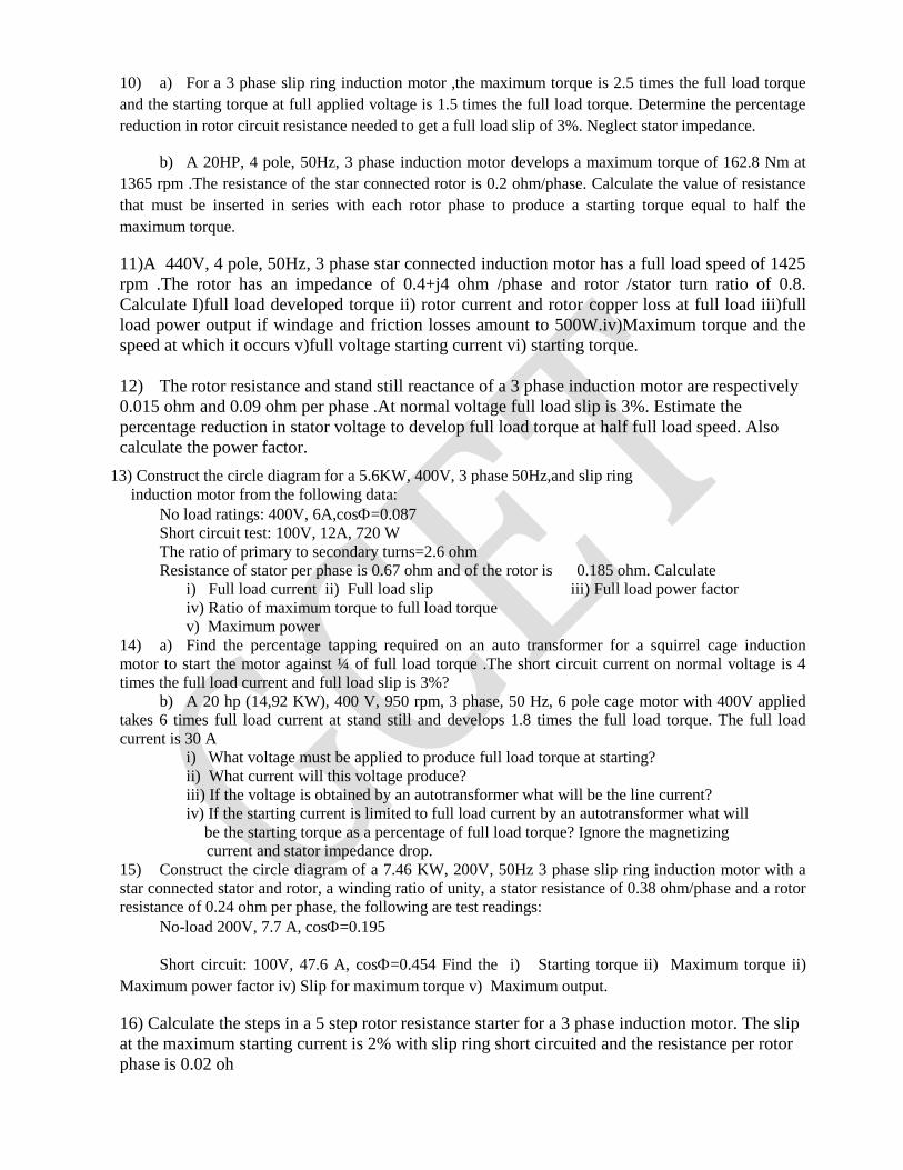
10) a) For a 3 phase slip ring induction motor ,the maximum torque is 2.5 times the full load torque
and the starting torque at full applied voltage is 1.5 times the full load torque. Determine the percentage
reduction in rotor circuit resistance needed to get a full load slip of 3%. Neglect stator impedance.
b) A 20HP, 4 pole, 50Hz, 3 phase induction motor develops a maximum torque of 162.8 Nm at
1365 rpm .The resistance of the star connected rotor is 0.2 ohm/phase. Calculate the value of resistance
that must be inserted in series with each rotor phase to produce a starting torque equal to half the
maximum torque.
11)A 440V, 4 pole, 50Hz, 3 phase star connected induction motor has a full load speed of 1425
rpm .The rotor has an impedance of 0.4+j4 ohm /phase and rotor /stator turn ratio of 0.8.
Calculate I)full load developed torque ii) rotor current and rotor copper loss at full load iii)full
load power output if windage and friction losses amount to 500W.iv)Maximum torque and the
speed at which it occurs v)full voltage starting current vi) starting torque.
12) The rotor resistance and stand still reactance of a 3 phase induction motor are respectively
0.015 ohm and 0.09 ohm per phase .At normal voltage full load slip is 3%. Estimate the
percentage reduction in stator voltage to develop full load torque at half full load speed. Also
calculate the power factor.
13) Construct the circle diagram for a 5.6KW, 400V, 3 phase 50Hz,and slip ring
induction motor from the following data:
No load ratings: 400V, 6A,cos=0.087
Short circuit test: 100V, 12A, 720 W
The ratio of primary to secondary turns=2.6 ohm
Resistance of stator per phase is 0.67 ohm and of the rotor is 0.185 ohm. Calculate
i) Full load current ii) Full load slip iii) Full load power factor
iv) Ratio of maximum torque to full load torque
v) Maximum power
14) a) Find the percentage tapping required on an auto transformer for a squirrel cage induction
motor to start the motor against ¼ of full load torque .The short circuit current on normal voltage is 4
times the full load current and full load slip is 3%?
b) A 20 hp (14,92 KW), 400 V, 950 rpm, 3 phase, 50 Hz, 6 pole cage motor with 400V applied
takes 6 times full load current at stand still and develops 1.8 times the full load torque. The full load
current is 30 A
i) What voltage must be applied to produce full load torque at starting?
ii) What current will this voltage produce?
iii) If the voltage is obtained by an autotransformer what will be the line current?
iv) If the starting current is limited to full load current by an autotransformer what will
be the starting torque as a percentage of full load torque? Ignore the magnetizing
current and stator impedance drop.
15) Construct the circle diagram of a 7.46 KW, 200V, 50Hz 3 phase slip ring induction motor with a
star connected stator and rotor, a winding ratio of unity, a stator resistance of 0.38 ohm/phase and a rotor
resistance of 0.24 ohm per phase, the following are test readings:
No-load 200V, 7.7 A, cos=0.195
Short circuit: 100V, 47.6 A, cos=0.454 Find the i) Starting torque ii) Maximum torque ii)
Maximum power factor iv) Slip for maximum torque v) Maximum output.
16) Calculate the steps in a 5 step rotor resistance starter for a 3 phase induction motor. The slip
at the maximum starting current is 2% with slip ring short circuited and the resistance per rotor
phase is 0.02 oh

17)a) A squirrel cage induction motor when started by means of a star/delta starter takes 180% of full
load line current and develops 35% of full load torque at starting. Calculate the starting torque and current
in terms of full load values, if an autotransformer with 75% tapping were employed.
b) A 10 hp motor when started at normal voltage with a star /delta switch in star position is found
to take an initial current of 1.7 times the full load current and give initial starting torque of 35% of full load
torque. Explain what happens when the motor started under the following conditions.
i) With an auto transformer giving 60% of normal voltage
ii) With resistance in series with the stator reducing the voltage to 60% of the normal.
Calculate in each case the value of starting current and torque in terms of the corresponding
quantities at full load.
21.Known Gaps:
22.Discussion Topics:
1. Materials used for the construction of Transformer
2.Types of Transformers and their Applications
3. Poly Phase Transformers and their applications in power systems
4. Poly Phase Induction Motors and their applications
5. Elimination of Cogging and Crawling in Induction Motors
6. Applications of Induction Generators in Present Power Generation Schemes.
23.References,Journals,Websites & E – Links:
24.Quality Measurement Sheets:
25.Student List:
26.Groupwise Student List for Discussion Topics:
Group -1:
Group -2:
Group -3:
Group -4:

Group -5:
Group -6:
Group -7: