Embed Size (px)
Citation preview
Splicing Connectors and Chassis Mount Terminal BlocksElectrical Installation Products
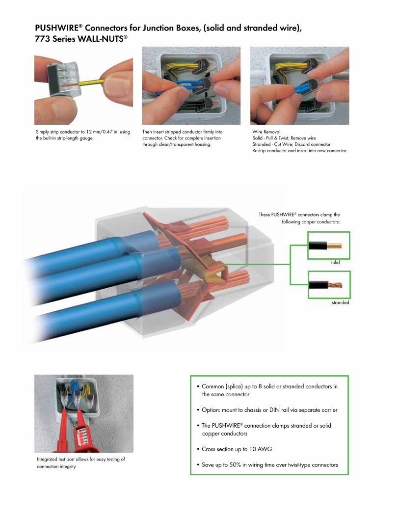
PUSHWIRE® Connectors for Junction Boxes, (solid and stranded wire),773 Series WALL-NUTS®
• Common (splice) up to 8 solid or stranded conductors in the same connector
• Option: mount to chassis or DIN rail via separate carrier
• The PUSHWIRE® connection clamps stranded or solid copper conductors
• Cross section up to 10 AWG
• Save up to 50% in wiring time over twist-type connectors
Simply strip conductor to 12 mm/0.47 in. using the built-in strip-length gauge
Then insert stripped conductor firmly into connector. Check for complete insertion through clear/transparent housing.
Wire RemovalSolid - Pull & Twist; Remove wireStranded - Cut Wire; Discard connectorRestrip conductor and insert into new connector
stranded
These PUSHWIRE® connectors clamp the following copper conductors:
solid
Integrated test port allows for easy testing of connection integrity
2 x 0.75 – 2.5 mm2 “s”
2 x AWG 18 – 12 “sol.”2 x 1.5 – 2.5 mm2 “r”
2 x AWG 16 – 12 “str.” (<19)
400 V/ 4 kV/2* 600 V 24 A 1000 V signs & fixtures Max. op. temp. 105°C
l 12 mm / 0.47 in
4 x 0.75 – 2.5 mm2 “s”
4 x AWG 18 – 12 “sol.”4 x 1.5 – 2.5 mm2 “r”
4 x AWG 16 – 12 “str.” (<19)
400 V/ 4 kV/2* 600 V 24 A 1000 V signs & fixtures Max. op. temp. 105°C
l 12 mm / 0.47 in
6 x 0.75 – 2.5 mm2 “s” 6 x AWG 18 – 12 “sol.”6 x 1.5 – 2.5 mm2 “r”
6 x AWG 16 – 12 “str.” (<19)
400 V/ 4 kV/2* 600 V 24 A 1000 V signs & fixtures Max. op. temp. 105°C
l 12 mm / 0.47 in
3 x 0.75 – 2.5 mm2 “s”
3 x AWG 18 – 12 “sol.”3 x 1.5 – 2.5 mm2 “r”
3 x AWG 16 – 12 “str.” (<19)
1 x 0.75 “sol.+rig.”
1 x AWG 18 “sol.+str.” (<19)400 V/ 4 kV/2* 600 V 24 A 1000 V signs & fixtures Max. op. temp. 105°Cl 12 mm / 0.47 in
3 x 1.5 – 6 mm2“s + st“
3 x AWG 14 –10“sol.“ +“str.“ (<19)400 V/ 4 kV/2* 600 V 32 A 1000 V signs & fixtures
Max. op. temp. 105°Cl 12 mm / 0.47 in
Item Pack.-unit No. pcs
Item Pack.-unit No. pcs
Item Pack.-unit No. pcs
8 x 0.75 – 2.5 mm2 “s” 8 x AWG 18 – 12 “sol.”8 x 1.5 – 2.5 mm2 “r”
8 x AWG 16 – 12 “str.” (<19)
400 V/ 4 kV/2* 600 V 24 A 1000 V signs & fixtures Max. op. temp. 105°C
l 12 mm / 0.47 in
Item Pack.-unit No. pcs
Item Pack.-unit No. pcs
Item Pack.-unit No. pcs
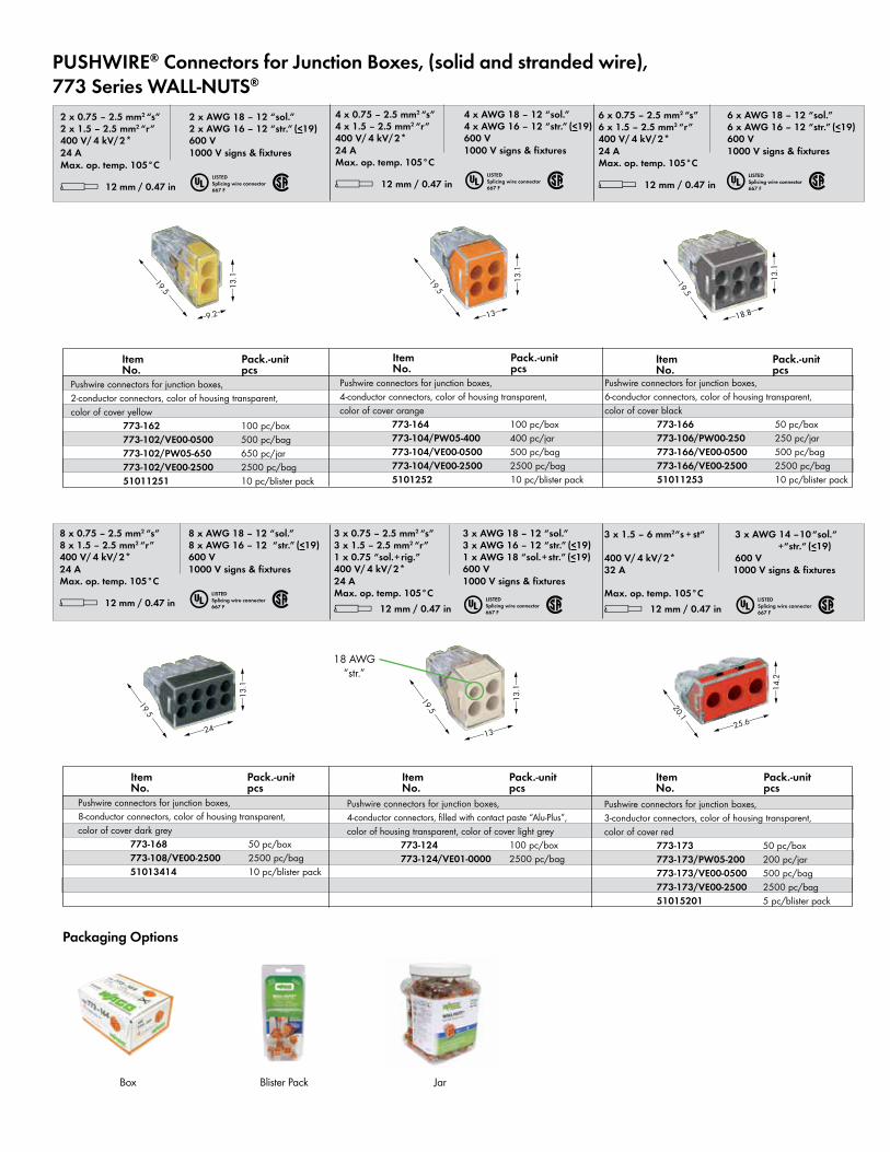
PUSHWIRE® Connectors for Junction Boxes, (solid and stranded wire),773 Series WALL-NUTS®
18 AWG “str.”
u 2LISTEDSplicing wire connector667 F u 2LISTED
Splicing wire connector667 F u 2LISTED
Splicing wire connector667 F
u 2LISTEDSplicing wire connector667 F u 2LISTED
Splicing wire connector667 F u 2LISTED
Splicing wire connector667 F
<_____19.5 _____>
<_____19.5 _____>
<_____19.5 _____>
<_1
3.1_>
<_1
3.1_>
<_1
3.1_>
<_18.8_><_13_><9.2>
<____19.5 ____>
<_1
3.1_>
<___24___>
<___20.1 ___>
<_1
4.2_>
<___25.6___>
<____19.5 ____>
<_1
3.1_>
<___13___>
Packaging Options
Box Blister Pack Jar
Pushwire connectors for junction boxes, 2-conductor connectors, color of housing transparent, color of cover yellow 773-162 100 pc/box 773-102/VE00-0500 500 pc/bag 773-102/PW05-650 650 pc/jar 773-102/VE00-2500 2500 pc/bag 51011251 10 pc/blister pack
Pushwire connectors for junction boxes, 4-conductor connectors, color of housing transparent, color of cover orange 773-164 100 pc/box 773-104/PW05-400 400 pc/jar 773-104/VE00-0500 500 pc/bag 773-104/VE00-2500 2500 pc/bag 5101252 10 pc/blister pack
Pushwire connectors for junction boxes, 6-conductor connectors, color of housing transparent, color of cover black 773-166 50 pc/box 773-106/PW00-250 250 pc/jar 773-166/VE00-0500 500 pc/bag 773-166/VE00-2500 2500 pc/bag 51011253 10 pc/blister pack
Pushwire connectors for junction boxes, 4-conductor connectors, filled with contact paste “Alu-Plus”, color of housing transparent, color of cover light grey 773-124 100 pc/box 773-124/VE01-0000 2500 pc/bag
Pushwire connectors for junction boxes, 3-conductor connectors, color of housing transparent, color of cover red 773-173 50 pc/box 773-173/PW05-200 200 pc/jar 773-173/VE00-0500 500 pc/bag 773-173/VE00-2500 2500 pc/bag 51015201 5 pc/blister pack
Pushwire connectors for junction boxes, 8-conductor connectors, color of housing transparent, color of cover dark grey 773-168 50 pc/box 773-108/VE00-2500 2500 pc/bag 51013414 10 pc/blister pack
* u2QOKfNSDFAJ9q:;[
3-x-0.75-–-1.5-mm2 “s”-
3-x-AWG-18-–-16-“sol.”5-x-0.75-–-1.5-mm2 “s”-
5-x-AWG-18-–-16-“sol.”
400 V/ 4 kV/2** 600 V, 10 A u18 A 600 V, 10 A 2l 10 – 13 mm / 0.45 in
8-x-0.75-–-1.5-mm2 “s”
8-x-AWG-18-–-16-“sol.”
400 V/ 4 kV/2** 600 V, 10 A u18 A 600 V, 10 A 2l 10 – 13 mm / 0.45 in
3-x-0,75-–-1,5-mm2«r»-
3-x-AWG-18-–-16-«s»5-x-0,75-–-1,5-mm2«r»-
5-x-AWG-18-–-16-«s»
400 V/ 4 kV/2** 600 V, 10 A u18 A 600 V, 10 A 2l 10 – 13 mm / 0.45 in
8-x-0,75-–-1,5-mm2«r»-
8-x-AWG-18-–-16-«s»
400 V/ 4 kV/2** 600 V, 10 A u18 A 600 V, 10 A 2l 10 – 13 mm / 0.45 in
Item Pack.-unit No. pcs
Item Pack.-unit No. pcs
Item Pack.-unit No. pcs
19,513
13,1
2 x 0.75–2.5 mm2 “s”
2 x AWG 18-12 “sol.”2 x 1.5–2.5 mm2 “r”
2 x AWG 16-12 “str.” (<19)
400 V/ 4 kV/2* 600 V 24 A 1000 V signs & fixturesMax. op. temp. 105oC
l 12 mm / 0.47 in
4 x 0.75 – 2.5 mm2 “s”
4 x AWG 18 – 12 “sol.”4 x 1.5 – 2.5 mm2 “r”
4 x AWG 16–12 “str.” (<19)
400 V/ 4 kV/2* 600 V 24 A 1000 V signs & fixturesMax. op. temp. 105oC
l 12 mm / 0.47 in
6 x 0.75 – 2.5 mm2 “s”
6 x AWG 18 – 12 “sol.”6 x 1.5 – 2.5 mm2 “r”
6 x AWG 16 – 12 “str.” (<19)
400 V/ 4 kV/2* 600 V 24 A 1000 V signs & fixturesMax. op. temp. 105oC
l 12 mm / 0.47 in
Item Pack.-unit No. pcs
Item Pack.-unit No. pcs
Item Pack.-unit No. pcs
* u2QOsKfNSDFAJ9:;[ * u2QOsKfNSDFbAJ:;[* u2fNSDFaCB:;[
4 x 0.75 – 2.5 mm2 “s”
4 x AWG 18 – 12 “sol.”4 x 1.5 – 2.5 mm2 “r”
4 x AWG 16 – 12 “str.” (<19)
400 V/ 4 kV/2* 4 x AWG 18 “str.” tincoated < 724 A 600 V 1000 V signs & fixturesMax. op. temp. 150oCl 12 mm / 0.47 in
8 x 0.75 – 2.5 mm2 “s”
8 x AWG 18 – 12 “sol.”8 x 1.5 – 2.5 mm2 “r”
8 x AWG 16 – 12 “str.” (<19)
400 V/ 4 kV/2* 600 V 24 A 1000 V signs & fixturesMax. op. temp. 105oC
l 12 mm / 0.47 in
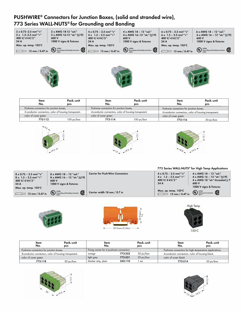
Carrier for Push-Wire Connectors
Carrier width 18 mm / 0.7 in
<_______ 59.5-mm /2.34-in ______>
<25
.5-m
m/
>1
in
High Temp
150oC
PUSHWIRE® Connectors for Junction Boxes, (solid and stranded wire),773 Series WALL-NUTS® for Grounding and Bonding
u 2LISTEDGrounding and bonding connectors64KA
u 2LISTEDSplicing wire connector667 F
<13
.1 >
<19.5 >< 24 >
<13
.1 >
<19.5 ><13 >
<13
.1 >
<19.5 ><18.8 >
<13
.1 >
<19.5 >
<9.2 >
Pushwire connectors for junction boxes, 6-conductor connectors, color of housing transparent, color of cover green 773-116 50 pc/box
Pushwire connectors for junction boxes, 4-conductor connectors, color of housing transparent, color of cover green 773-114 100 pc/box
Pushwire connectors for junction boxes, 2-conductor connectors, color of housing transparent, color of cover green 773-112 100 pc/box
Pushwire connectors for high temperature applications, 4-conductor connectors, color of housing black, color of cover black 773-514 50 pc/box
Pushwire connectors for junction boxes, 8-conductor connectors, color of housing transparent, color of cover green 773-118 50 pc/box
Fixing carrier for 4 pushwire connectors orange 773-332 50 pc/boxlight grey 773-331 50 pc/boxMarker strip, plain 243-110 1 ea
u 2LISTEDGrounding and bonding connectors64KA u 2LISTED
Grounding and bonding connectors64KA
u 2LISTEDGrounding and bonding connectors64KA
773 Series WALL-NUTS® for High Temp Applications
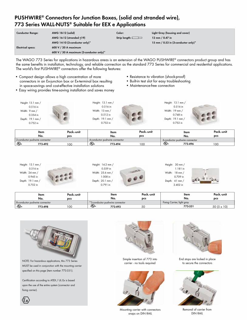
The WAGO 773 Series for applications in hazardous areas is an extension of the WAGO PUSHWIRE® connectors product group and has the same benefits in installation, technology, and reliable connection as the standard 773 Series for commercial and residential applications. The world's first PUSHWIRE® connectors offer the following features:
Item No.
Pack.-unit pcs
• Compact design allows a high concentration of more connectors in an Ex-junction box or Ex-terminal box resulting in space-savings and cost-effective installation solutions• Easy wiring provides time-saving installation and saves money
• Resistance to vibration (shock-proof)• Built-in test slot for easy troubleshooting• Maintenance-free connection
4
Item No.
Pack.-unit pcs
Item No.
Pack.-unit pcs
2-conductor pushwire connector773-492 100 773-494 773-496
4-conductor pushwire connector 6-conductor pushwire connector
Item No.
Pack.-unit pcs
Item No.
Pack.-unit pcs
8-conductor pushwire connector773-498 773-493 50
*3-conductor pushwire connector
Item No.
Pack.-unit pcs
Fixing Carrier, light gray
NOTE: For hazardous applications, this 773 Series
MUST be used in conjunction with the mounting carrier
specified on this page (item number 773-331).
Certification according to ATEX / UL Ex is based
upon the use of the entire system (connector and
fixing carrier).
Conductor Range: AWG 18-12 (solid)
AWG 16-12 (stranded <19)
AWG 14-10 (3-conductor only)*
Electrical specs: 600 V / 20 A maximum
600 V / 30 A maximum (3-conductor only)*
Height: 13.1 mm / 0.516 inWidth: 24 mm / 0.945 inDepth: 19.1 mm / 0.752 in
Height: 14.2 mm / 0.559 inWidth: 25.6 mm / 1.008 inDepth: 20.1 mm / 0.791 in
Height: 13.1 mm / 0.516 inWidth: 9 mm / 0.354 inDepth: 19.1 mm / 0.752 in
Height: 13.1 mm / 0.516 inWidth: 13 mm / 0.512 inDepth: 19.1 mm / 0.752 in
Height: 13.1 mm / 0.516 inWidth: 19 mm / 0.748 inDepth: 19.1 mm / 0.752 in
Height: 30 mm / 1.181 inWidth: 18 mm / 0.709 inDepth: 61 mm / 2.402 in
100
100
100r r r
r
Color: Light Gray (housing and cover)
Strip length: l 12 mm / 0.47 in
15 mm / 0.53 in (3-conductor only)*
r
Simple insertion of 773 into carrier - no tools required
End stops are locked in place to secure the connectors
Mounting carrier with connectors snaps on DIN RAIL
Removal of carrier from DIN RAIL
773-331 50 (5 x 10)
PUSHWIRE® Connectors for Junction Boxes, (solid and stranded wire),773 Series WALL-NUTS® Suitable for EEX e Applications
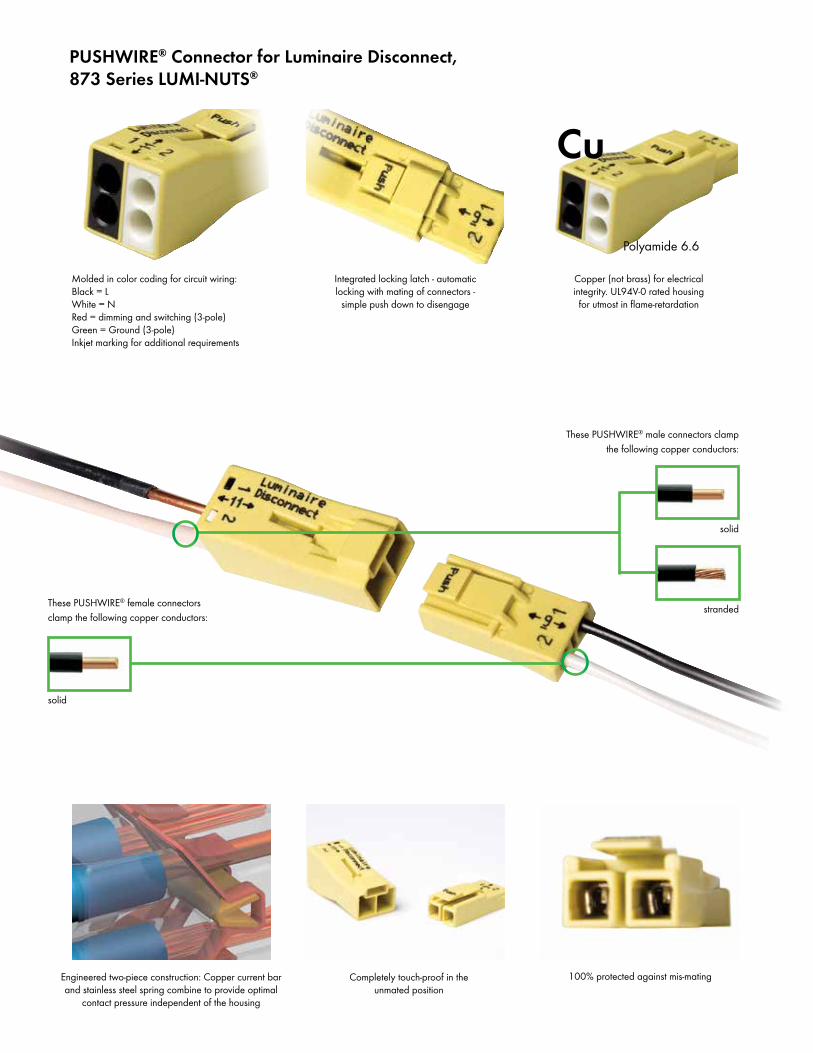
These PUSHWIRE® male connectors clamp the following copper conductors:
solid
These PUSHWIRE® female connectors clamp the following copper conductors:
solid
Molded in color coding for circuit wiring:Black = LWhite = NRed = dimming and switching (3-pole)Green = Ground (3-pole)Inkjet marking for additional requirements
Integrated locking latch - automatic locking with mating of connectors -
simple push down to disengage
Copper (not brass) for electrical integrity. UL94V-0 rated housing for utmost in flame-retardation
100% protected against mis-matingCompletely touch-proof in the unmated position
Engineered two-piece construction: Copper current bar and stainless steel spring combine to provide optimal
contact pressure independent of the housing
PUSHWIRE® Connector for Luminaire Disconnect,873 Series LUMI-NUTS®
Cu
Polyamide 6.6
stranded
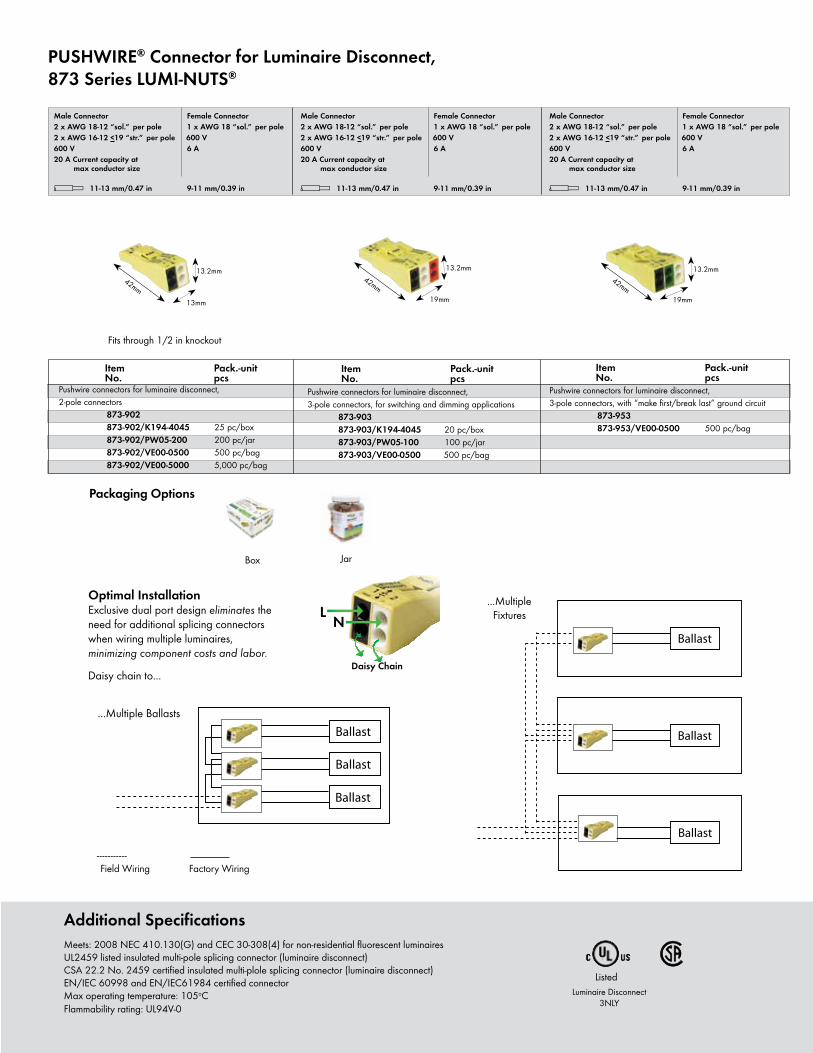
Optimal InstallationExclusive dual port design eliminates the need for additional splicing connectors when wiring multiple luminaires, minimizing component costs and labor.
Daisy chain to...
PUSHWIRE® Connector for Luminaire Disconnect,873 Series LUMI-NUTS®
Ballast
Ballast
Ballast
...Multiple Fixtures
----------- Field Wiring Factory Wiring
Item Pack.-unit No. pcs
Item Pack.-unit No. pcs
Listed
PUSHWIRE® Connector for Luminaire Disconnect,873 Series LUMI-NUTS®
Ballast
Ballast
Ballast
* u2QOKfNSDFAJ9q:;[
3-x-0.75-–-1.5-mm2 “s”-
3-x-AWG-18-–-16-“sol.”5-x-0.75-–-1.5-mm2 “s”-
5-x-AWG-18-–-16-“sol.”
400 V/ 4 kV/2** 600 V, 10 A u18 A 600 V, 10 A 2l 10 – 13 mm / 0.45 in
8-x-0.75-–-1.5-mm2 “s”
8-x-AWG-18-–-16-“sol.”
400 V/ 4 kV/2** 600 V, 10 A u18 A 600 V, 10 A 2l 10 – 13 mm / 0.45 in
3-x-0,75-–-1,5-mm2«r»-
3-x-AWG-18-–-16-«s»5-x-0,75-–-1,5-mm2«r»-
5-x-AWG-18-–-16-«s»
400 V/ 4 kV/2** 600 V, 10 A u18 A 600 V, 10 A 2l 10 – 13 mm / 0.45 in
8-x-0,75-–-1,5-mm2«r»-
8-x-AWG-18-–-16-«s»
400 V/ 4 kV/2** 600 V, 10 A u18 A 600 V, 10 A 2l 10 – 13 mm / 0.45 in
Male Connector Female Connector2 x AWG 18-12 “sol.” per pole
1 x AWG 18 “sol.” per pole
2 x AWG 16-12 <19 “str.” per pole
600 V600 V 6 A20 A Current capacity at max conductor size
l 11-13 mm/0.47 in 9-11 mm/0.39 in
Item Pack.-unit No. pcs
Male Connector Female Connector2 x AWG 18-12 “sol.” per pole
1 x AWG 18 “sol.” per pole
2 x AWG 16-12 <19 “str.” per pole
600 V600 V 6 A20 A Current capacity at max conductor size
l 11-13 mm/0.47 in 9-11 mm/0.39 in
Male Connector Female Connector2 x AWG 18-12 “sol.” per pole
1 x AWG 18 “sol.” per pole
2 x AWG 16-12 <19 “str.” per pole
600 V600 V 6 A20 A Current capacity at max conductor size
l 11-13 mm/0.47 in 9-11 mm/0.39 in
L NDaisy Chain
Additional SpecificationsMeets: 2008 NEC 410.130(G) and CEC 30-308(4) for non-residential fluorescent luminairesUL2459 listed insulated multi-pole splicing connector (luminaire disconnect)CSA 22.2 No. 2459 certified insulated multi-plole splicing connector (luminaire disconnect)EN/IEC 60998 and EN/IEC61984 certified connectorMax operating temperature: 105oCFlammability rating: UL94V-0
Luminaire Disconnect3NLY
Fits through 1/2 in knockout
42mm
13.2mm
13mm
42mm
13.2mm
19mm
42mm
13.2mm
19mm
Packaging Options
Box Jar
...Multiple Ballasts
Pushwire connectors for luminaire disconnect, 2-pole connectors 873-902 873-902/K194-4045 25 pc/box 873-902/PW05-200 200 pc/jar 873-902/VE00-0500 500 pc/bag 873-902/VE00-5000 5,000 pc/bag
Pushwire connectors for luminaire disconnect, 3-pole connectors, for switching and dimming applications 873-903 873-903/K194-4045 20 pc/box 873-903/PW05-100 100 pc/jar 873-903/VE00-0500 500 pc/bag
Pushwire connectors for luminaire disconnect, 3-pole connectors, with “make first/break last” ground circuit 873-953 873-953/VE00-0500 500 pc/bag
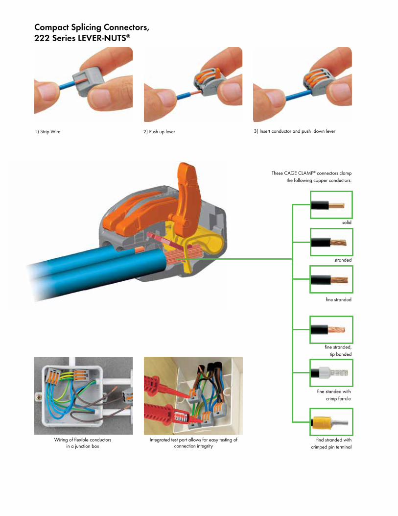
1) Strip Wire 2) Push up lever
Wiring of flexible conductors in a junction box
stranded
fine stranded, tip bonded
find stranded with crimped pin terminal
Compact Splicing Connectors,222 Series LEVER-NUTS®
Integrated test port allows for easy testing of connection integrity
3) Insert conductor and push down lever
solid
fine stranded
fine standed with crimp ferrule
These CAGE CLAMP® connectors clamp the following copper conductors:
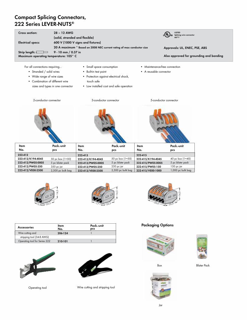
Compact Splicing Connectors,222 Series LEVER-NUTS®
Cross section: 28 – 12 AWG (solid, stranded and flexible) Electrical specs: 600 V (1000 V signs and fixtures) 20 A maximum * Based on 2008 NEC current rating of max conductor size
Strip length: l 9 - 10 mm / 0.37 inMaximum operating temperature: 105° C
Item No.
Pack.-unit pcs
222-413222-413/K194-4045222-413/PW05-0005222-413/PW05-250222-413/VE00-2500
50 pc box (1=50)5 pc blister pack250 pc jar2,500 pc bulk bag
Item No.
Pack.-unit pcs
222-415222-415/K194-4045222-415/PW05-0005222-415/PW05-150222-415/VE00-1000
40 pc box (1=40)5 pc blister pack150 pc jar1,000 pc bulk bag
Item No.
Pack.-unit pcsAccessories
Item No.
Pack.-unit pcs
222-412222-412/K194-4045222-412/PW05-0005222-412/PW05-350222-412/VE00-2500
50 pc box (1=50)5 pc blister pack350 pc jar2,500 pc bulk bag
Wire cutting and stripping tool (34-8 AWG)Operating tool for Series 222
206-124
210-101
Operating tool
1
1
r LISTEDSplicing wire connector667 F
2-conductor connector 3-conductor connector 5-conductor connector
Approvals: UL, ENEC, PSE, ABS
Also approved for grounding and bonding
For all connections requiring... • Stranded / solid wires • Wide range of wire sizes • Combination of different wire sizes and types in one connector
• Small space consumption • Built-in test point • Protection against electrical shock, touch safe • Low installed cost and safe operation
• Maintenance-free connection • A reusable connector
Wire cutting and stripping tool
Packaging Options
Box Blister Pack
Jar
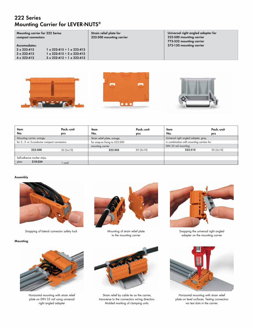
222 SeriesMounting Carrier for LEVER-NUTS®
Mounting carrier for 222 Seriescompact connectors
Accomodates:2 x 222-415 1 x 222-415 + 1 x 222-4133 x 222-413 1 x 222-415 + 2 x 222-4124 x 222-412 3 x 222-412 + 1 x 222-413
Item No.
Pack.-unit pcs
50 (5x10)
Item No.
Pack.-unit pcs
50 (5x10)
Item No.
Pack.-unit pcs
50 (5x10)
1 card
Strain relief plate for222-500 mounting carrier
Universal right angled adapter for222-500 mounting carrier773-332 mounting carrier273-150 mounting carrier
Assembly
Mounting
Snapping of lateral connector safety lock Mounting of strain relief plate to the mounting carrier
Snapping the universal right angled adapter on the mounting carrier
Horizontal mounting with strain relief plate on DIN 35 rail using universal
right angled adapter
Strain relief by cable tie on the carrier, transverse to the connectors wiring direction.
Molded marking of clamping units.
Horizontal mounting with strain relief plate on level surfaces. Testing connectors
via test slots in the carrier.
Strain relief plate, orange,for snap-on fixing to 222-500 mounting carrier 222-505
Universal right angled adapter, gray,in combination with mounting carriers for DIN 35 rail mounting 222-510
Mounting carrier, orange,for 2-, 3- or 5-conductor compact connectors 222-500
Self-adhesive marker strips,plain 210-334
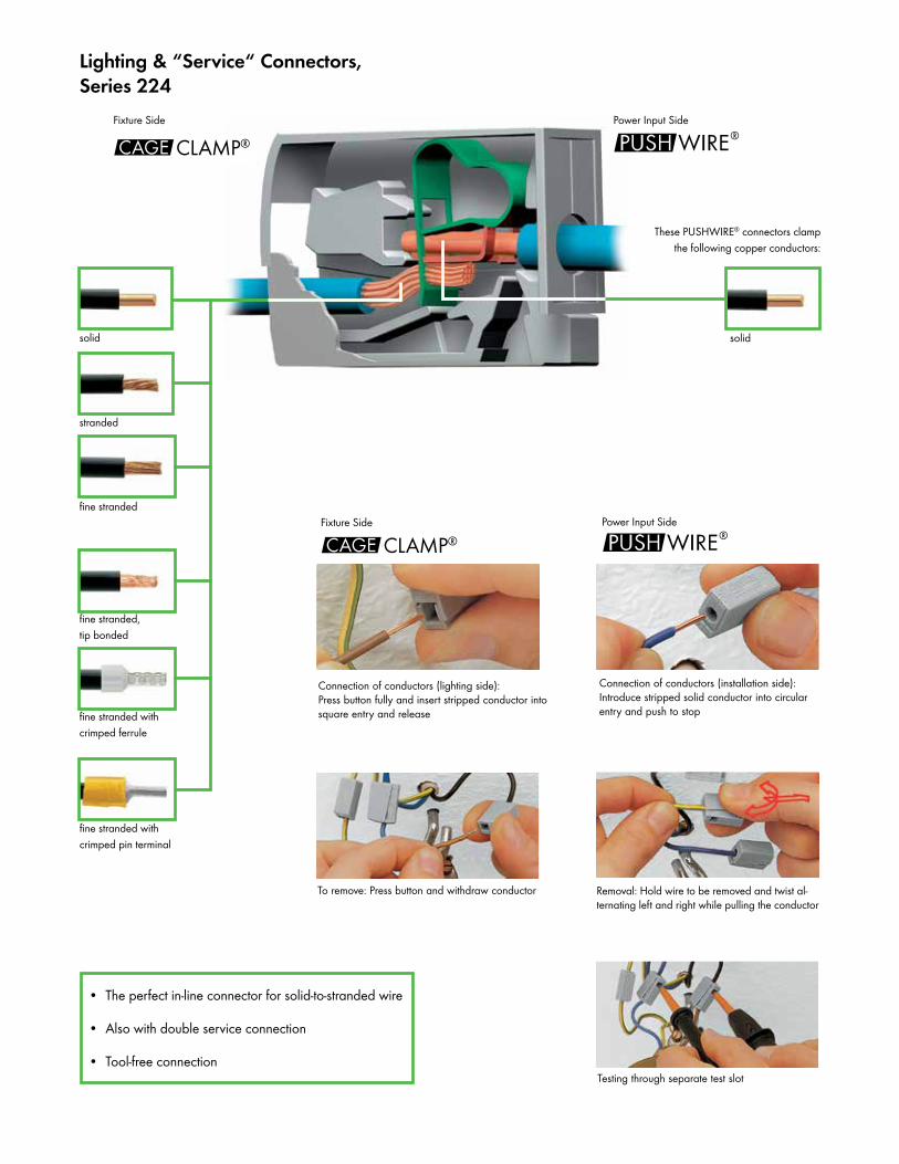
Removal: Hold wire to be removed and twist al-ternating left and right while pulling the conductor
• The perfect in-line connector for solid-to-stranded wire
• Also with double service connection
• Tool-free connection
Power Input SideFixture Side
Lighting & “Service“ Connectors,Series 224
stranded
fine stranded
fine stranded, tip bonded
fine stranded with crimped ferrule
fine stranded with crimped pin terminal
solid solid
To remove: Press button and withdraw conductor
Connection of conductors (installation side):Introduce stripped solid conductor into circular entry and push to stop
Testing through separate test slot
Fixture Side Power Input Side
Connection of conductors (lighting side):Press button fully and insert stripped conductor into square entry and release
These PUSHWIRE® connectors clamp the following copper conductors:
°CLAMP®
°CLAMP®
$
$
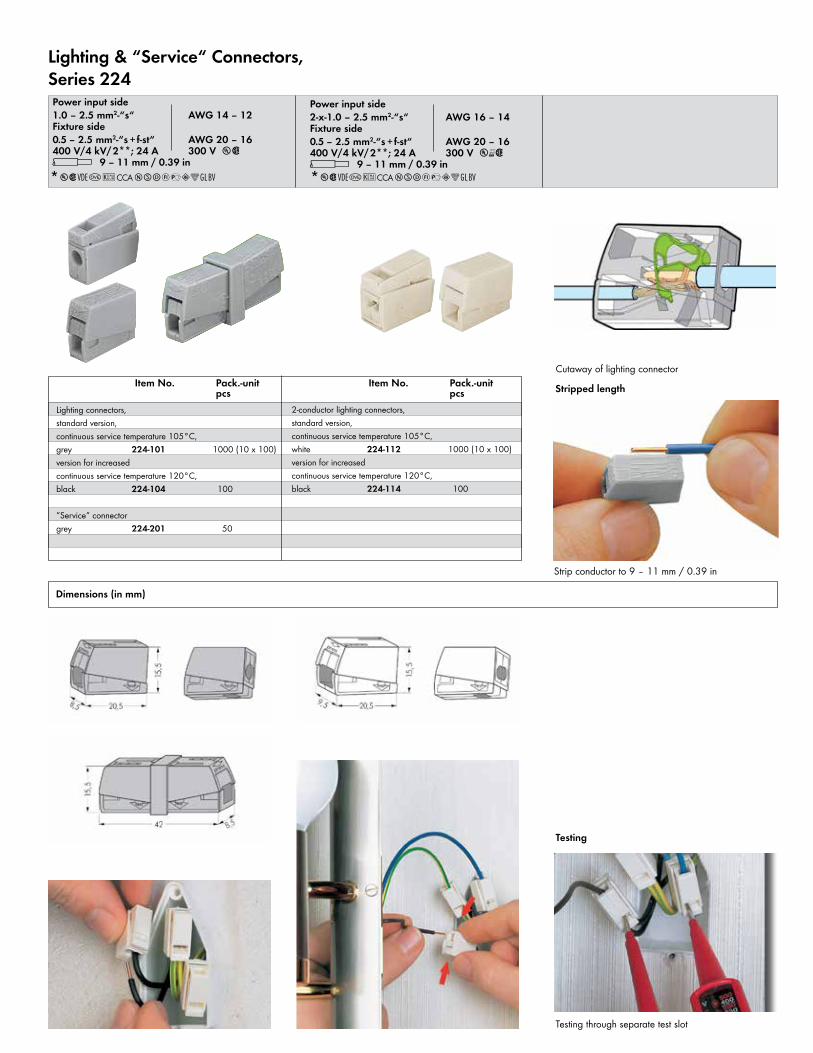
Item No. Pack.-unit pcs
Item No. Pack.-unit pcs
Lighting & “Service“ Connectors,Series 224
*u2QOKCCANSDFaAJ:; *u2QOKCCANSDFaAJ:;
Lighting connectors, standard version, continuous service temperature 105°C,grey 224-101 1000 (10 x 100)version for increased continuous service temperature 120°C,black 224-104 100
“Service“ connectorgrey 224-201 50
2-conductor lighting connectors, standard version, continuous service temperature 105°C,white 224-112 1000 (10 x 100)version for increased continuous service temperature 120°C,black 224-114 100
Dimensions (in mm)
Power input side1.0 – 2.5 mm2-“s“ AWG 14 – 12Fixture side0.5 – 2.5 mm2-“s +f-st“ AWG 20 – 16400 V/4 kV/2**; 24 A 300 V u2l 9 – 11 mm / 0.39 in
Power input side2-x-1.0 – 2.5 mm2-“s“ AWG 16 – 14Fixture side0.5 – 2.5 mm2-“s +f-st“ AWG 20 – 16400 V/4 kV/2**; 24 A 300 V u‑2l 9 – 11 mm / 0.39 in
Strip conductor to 9 – 11 mm / 0.39 in
Stripped length
Testing
Testing through separate test slot
Cutaway of lighting connector
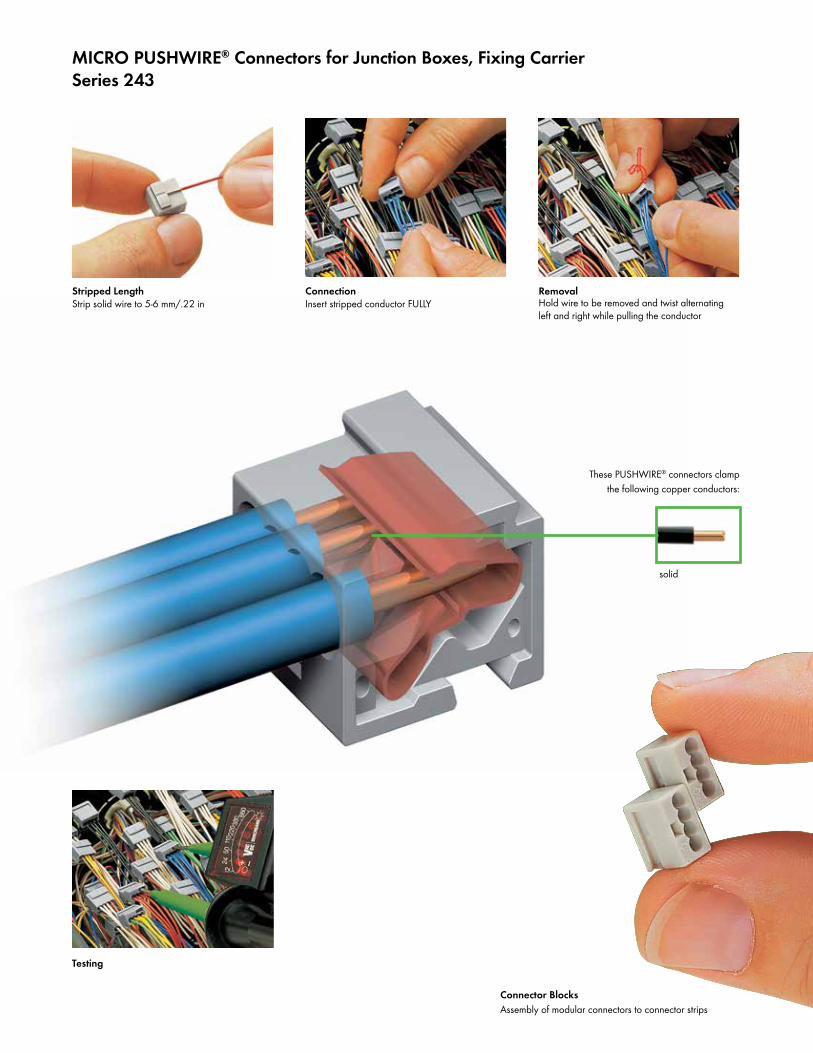
Stripped LengthStrip solid wire to 5-6 mm/.22 in
ConnectionInsert stripped conductor FULLY
Testing
MICRO PUSHWIRE® Connectors for Junction Boxes, Fixing Carrier Series 243
solid
RemovalHold wire to be removed and twist alternating left and right while pulling the conductor
These PUSHWIRE® connectors clamp the following copper conductors:
Connector BlocksAssembly of modular connectors to connector strips
Item No. Pack.-unit pcs
Dimensions (in mm)
* You can find approvals on the Internet at www.wago.us **When using wires of the same diameter only, 0.5 Ø mm/AWG 24 or 1.0 Ø mm/AWG 18 are also possible
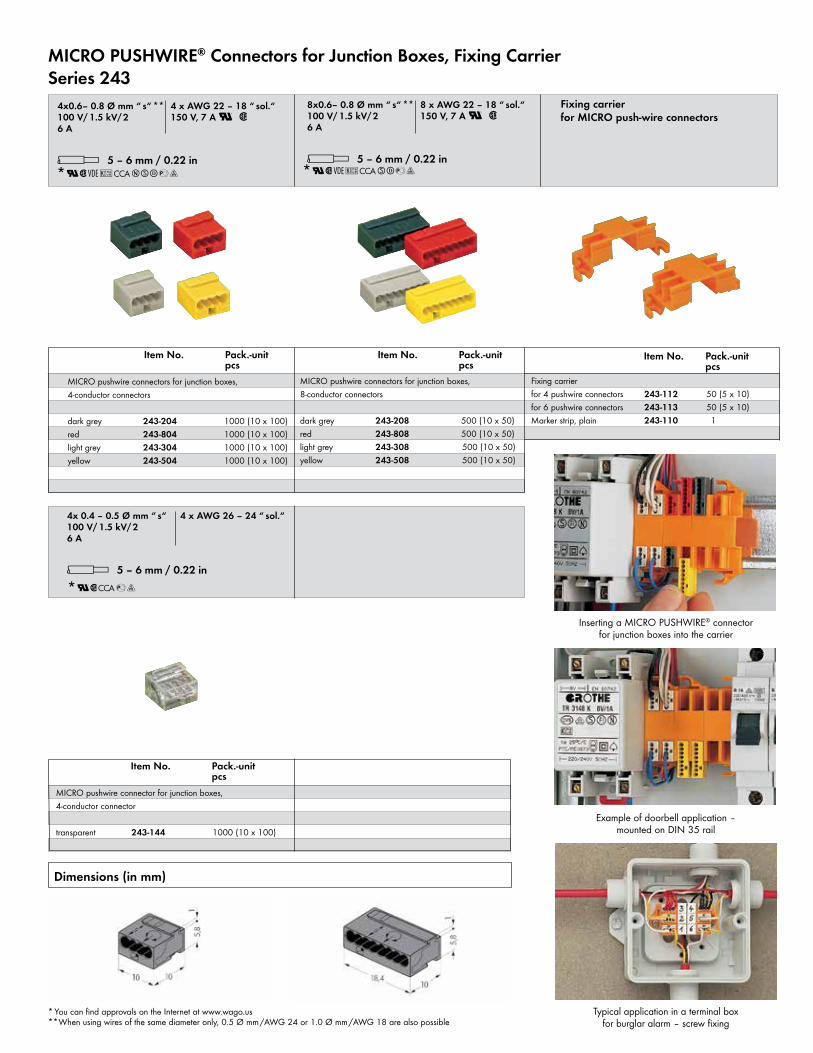
Typical application in a terminal box for burglar alarm – screw fixing
Example of doorbell application – mounted on DIN 35 rail
Inserting a MICRO PUSHWIRE® connector for junction boxes into the carrier
Item No. Pack.-unit pcs
MICRO PUSHWIRE® Connectors for Junction Boxes, Fixing Carrier Series 243
*U2QKCCASDaq*U2QKCCANSDaq
*U2CCAaq
8x0.6– 0.8 Ø mm “ s“ **
8 x AWG 22 – 18 “ sol.“100 V/ 1.5 kV/2 150 V, 7 A U 26 A
l 5 – 6 mm / 0.22 in
4x0.6– 0.8 Ø mm “ s“ **
4 x AWG 22 – 18 “ sol.“100 V/ 1.5 kV/2 150 V, 7 A U 26 A
l 5 – 6 mm / 0.22 in
4x 0.4 – 0.5 Ø mm “ s“
4 x AWG 26 – 24 “ sol.“100 V/ 1.5 kV/26 A
l 5 – 6 mm / 0.22 in
Fixing carrier for MICRO push-wire connectors
Item No. Pack.-unit pcs
Item No. Pack.-unit pcs
Fixing carrierfor 4 pushwire connectors 243-112 50 (5 x 10)for 6 pushwire connectors 243-113 50 (5 x 10)Marker strip, plain 243-110 1
MICRO pushwire connectors for junction boxes, 8-conductor connectors
dark grey 243-208 500 (10 x 50) red 243-808 500 (10 x 50)light grey 243-308 500 (10 x 50) yellow 243-508 500 (10 x 50)
MICRO pushwire connectors for junction boxes, 4-conductor connectors
dark grey 243-204 1000 (10 x 100) red 243-804 1000 (10 x 100)light grey 243-304 1000 (10 x 100) yellow 243-504 1000 (10 x 100)
MICRO pushwire connector for junction boxes, 4-conductor connector
transparent 243-144 1000 (10 x 100)
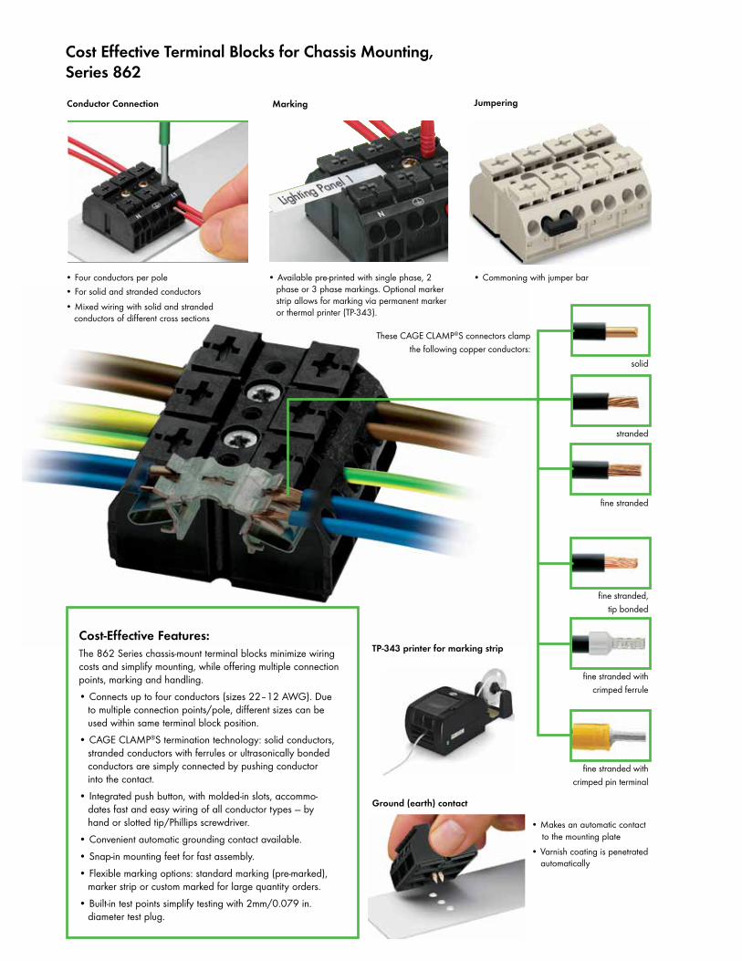
Cost Effective Terminal Blocks for Chassis Mounting,Series 862
stranded
fine stranded
fine stranded, tip bonded
fine stranded with crimped ferrule
fine stranded with crimped pin terminal
solid
• Makes an automatic contact to the mounting plate • Varnish coating is penetrated automatically
• Four conductors per pole • For solid and stranded conductors• Mixed wiring with solid and stranded conductors of different cross sections
• Available pre-printed with single phase, 2 phase or 3 phase markings. Optional marker strip allows for marking via permanent marker or thermal printer (TP-343).
Ground (earth) contact
Conductor Connection Marking Jumpering
• Commoning with jumper bar
Cost-Effective Features:The 862 Series chassis-mount terminal blocks minimize wiring costs and simplify mounting, while offering multiple connection points, marking and handling. • Connects up to four conductors (sizes 22–12 AWG). Due to multiple connection points/pole, different sizes can be used within same terminal block position.• CAGE CLAMP®S termination technology: solid conductors, stranded conductors with ferrules or ultrasonically bonded conductors are simply connected by pushing conductor into the contact.• Integrated push button, with molded-in slots, accommo- dates fast and easy wiring of all conductor types — by hand or slotted tip/Phillips screwdriver.• Convenient automatic grounding contact available.• Snap-in mounting feet for fast assembly.• Flexible marking options: standard marking (pre-marked), marker strip or custom marked for large quantity orders.• Built-in test points simplify testing with 2mm/0.079 in. diameter test plug.
These CAGE CLAMP®S connectors clamp the following copper conductors:
TP-343 printer for marking strip
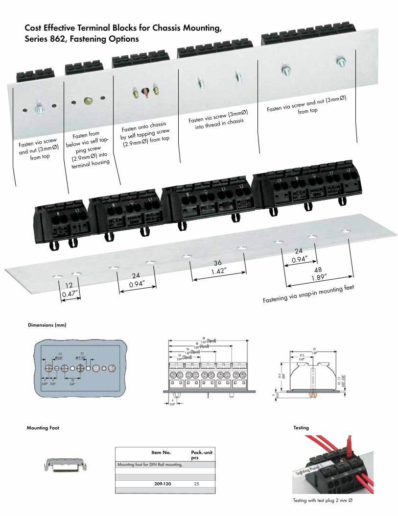
120.47”
240.94”
361.42”
240.94”
481.89”
Fasten via screw
and nut (3mmØ)
from top
Fasten from
below via self tap-
ping screw
(2.9mmØ) into
terminal housing
Fasten onto chassis
by self tapping screw
(2.9mmØ) from top
Fasten via screw (3mmØ)
into thread in chassis
Fasten via screw and nut (3mmØ)
from top
Fastening via snap-in mounting feet
Dimensions (mm)
Cost Effective Terminal Blocks for Chassis Mounting,Series 862, Fastening Options
Item No. Pack.-unit pcs
Mounting foot for DIN Rail mounting,
209-120 25
Mounting Foot
Testing with test plug 2 mm Ø
Testing
Testing
2.3 mm /0.091 in Ø, yellow210-137 50 (5 x 10)
862-0552 862-0652 500862-1552 862-1652 500862-2552 862-2652 500
862-0562 862-0662 500862-1562 862-1662 500862-2562 862-2662 500
862-0532 862-0632 500862-1532 862-1632 500862-2532 862-2632 500
862-0503 862-0603 250 862-1503 862-1603 250 862-2503 862-2603 250862-8503 862-8603 250862-9503 862-9603 250
862-0533 862-0633 250862-1533 862-1633 250862-2533 862-2633 250862-8533 862-8633 250862-9533 862-9633 250
862-0593 862-0693 250862-1593 862-1693 250862-2593 862-2693 250862-8593 862-8693 250862-9593 862-9693 250
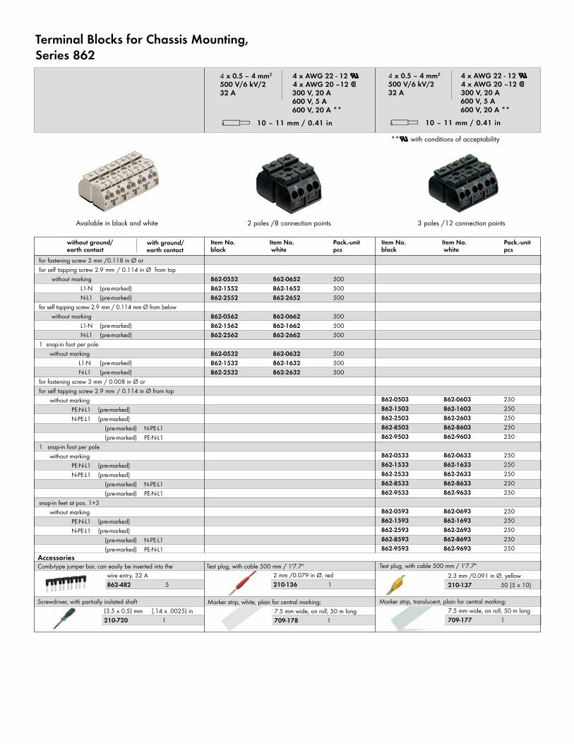
Terminal Blocks for Chassis Mounting,Series 862
4 x 0.5 – 4 mm2 4 x AWG 22 - 12 U 500 V/6 kV/2 4 x AWG 20 –12 232 A 300 V, 20 A 600 V, 5 A 600 V, 20 A ** l 10 – 11 mm / 0.41 in
Item No. Item No. Pack.-unit black white pcs
Item No. Item No. Pack.-unit black white pcs
Comb-type jumper bar, can easily be inserted into the
Available in black and white 2 poles /8 connection points 3 poles /12 connection points
for fastening screw 3 mm / 0.008 in Ø orfor self tapping screw 2.9 mm / 0.114 in Ø from top without marking PE-N-L1 (pre-marked) N-PE-L1 (pre-marked) (pre-marked) N-PE-L1 (pre-marked) PE-N-L11 snap-in foot per pole without marking PE-N-L1 (pre-marked) N-PE-L1 (pre-marked) (pre-marked) N-PE-L1 (pre-marked) PE-N-L1snap-in feet at pos. 1+3 without marking PE-N-L1 (pre-marked) N-PE-L1 (pre-marked) (pre-marked) N-PE-L1 (pre-marked) PE-N-L1
for fastening screw 3 mm /0.118 in Ø orfor self tapping screw 2.9 mm / 0.114 in Ø from top without marking L1-N (pre-marked) N-L1 (pre-marked)for self tapping screw 2.9 mm / 0.114 mm Ø from below without marking L1-N (pre-marked) N-L1 (pre-marked) 1 snap-in foot per pole without marking L1-N (pre-marked) N-L1 (pre-marked)
wire entry, 32 A 862-482 5
Accessories
Screwdriver, with partially inslated shaft(3.5 x 0.5) mm (.14 x .0025) in210-720 1
Test plug, with cable 500 mm / 1'7.7"2 mm /0.079 in Ø, red210-136 1
Marker strip, white, plain for central marking;7.5 mm wide, on roll, 50 m long709-178 1
Test plug, with cable 500 mm / 1'7.7"
Marker strip, translucent, plain for central marking;7.5 mm wide, on roll, 50 m long709-177 1
without ground/earth contact
with ground/earth contact
4 x 0.5 – 4 mm2 4 x AWG 22 - 12 U 500 V/6 kV/2 4 x AWG 20 –12 232 A 300 V, 20 A 600 V, 5 A 600 V, 20 A ** l 10 – 11 mm / 0.41 in
**U with conditions of acceptability
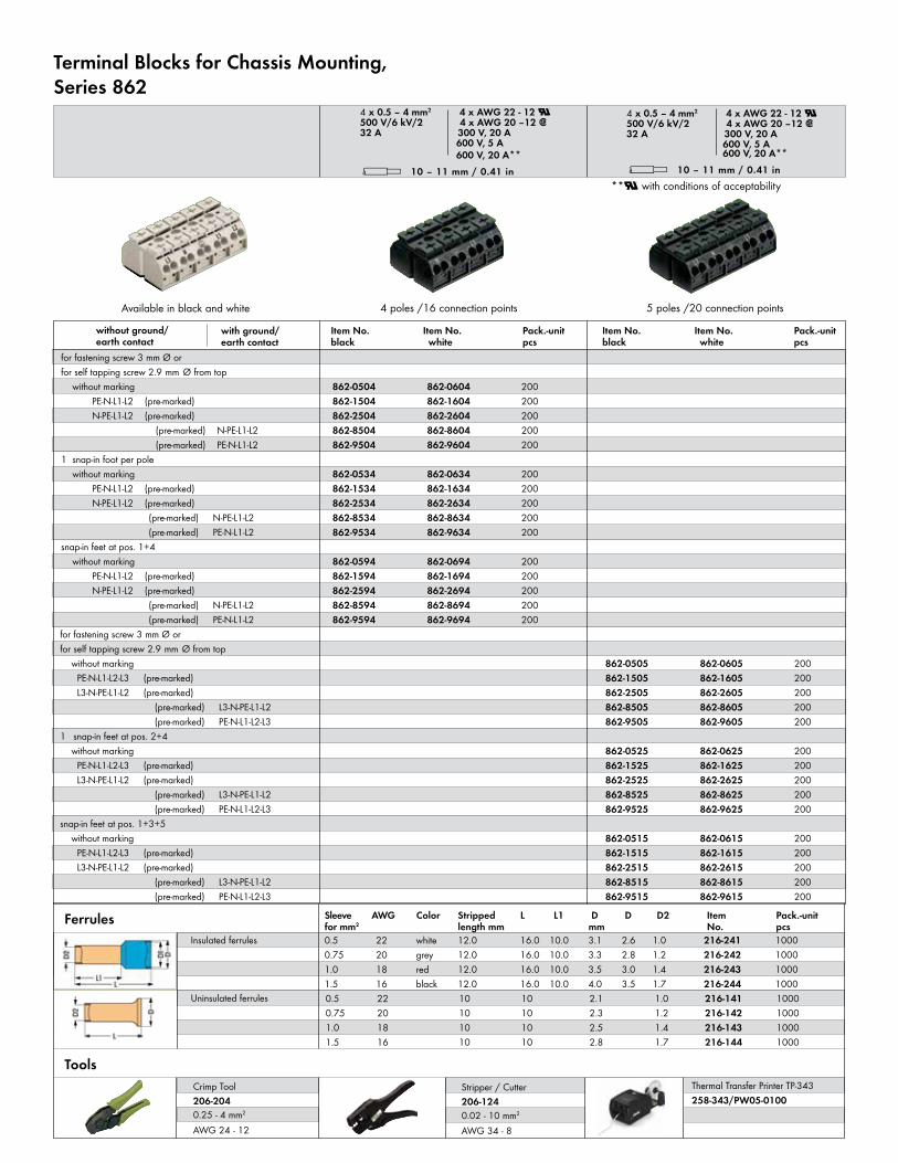
0.5 22 10 10 2.1 1.0 216-141 10000.75 20 10 10 2.3 1.2 216-142 10001.0 18 10 10 2.5 1.4 216-143 10001.5 16 10 10 2.8 1.7 216-144 1000
0.5 22 white 12.0 16.0 10.0 3.1 2.6 1.0 216-241 10000.75 20 grey 12.0 16.0 10.0 3.3 2.8 1.2 216-242 10001.0 18 red 12.0 16.0 10.0 3.5 3.0 1.4 216-243 10001.5 16 black 12.0 16.0 10.0 4.0 3.5 1.7 216-244 1000
Sleeve AWG Color Stripped L L1 D D D2 Item Pack.-unitfor mm2 length mm mm No. pcs
Insulated ferrules
Uninsulated ferrules
Ferrules
Crimp Tool206-2040.25 - 4 mm2 AWG 24 - 12
Stripper / Cutter206-1240.02 - 10 mm2 AWG 34 - 8
Tools
4 poles /16 connection points 5 poles /20 connection pointsAvailable in black and white
862-0504 862-0604 200862-1504 862-1604 200862-2504 862-2604 200862-8504 862-8604 200862-9504 862-9604 200
862-0534 862-0634 200862-1534 862-1634 200862-2534 862-2634 200862-8534 862-8634 200862-9534 862-9634 200
862-0594 862-0694 200862-1594 862-1694 200862-2594 862-2694 200862-8594 862-8694 200862-9594 862-9694 200
862-0505 862-0605 200862-1505 862-1605 200862-2505 862-2605 200862-8505 862-8605 200862-9505 862-9605 200
862-0525 862-0625 200862-1525 862-1625 200862-2525 862-2625 200862-8525 862-8625 200862-9525 862-9625 200
862-0515 862-0615 200862-1515 862-1615 200862-2515 862-2615 200862-8515 862-8615 200862-9515 862-9615 200
for fastening screw 3 mm Ø orfor self tapping screw 2.9 mm Ø from top without marking PE-N-L1-L2 (pre-marked) N-PE-L1-L2 (pre-marked) (pre-marked) N-PE-L1-L2 (pre-marked) PE-N-L1-L21 snap-in foot per pole without marking PE-N-L1-L2 (pre-marked) N-PE-L1-L2 (pre-marked) (pre-marked) N-PE-L1-L2 (pre-marked) PE-N-L1-L2snap-in feet at pos. 1+4 without marking PE-N-L1-L2 (pre-marked) N-PE-L1-L2 (pre-marked) (pre-marked) N-PE-L1-L2 (pre-marked) PE-N-L1-L2for fastening screw 3 mm Ø orfor self tapping screw 2.9 mm Ø from top without marking PE-N-L1-L2-L3 (pre-marked) L3-N-PE-L1-L2 (pre-marked) (pre-marked) L3-N-PE-L1-L2 (pre-marked) PE-N-L1-L2-L31 snap-in feet at pos. 2+4 without marking PE-N-L1-L2-L3 (pre-marked) L3-N-PE-L1-L2 (pre-marked) (pre-marked) L3-N-PE-L1-L2 (pre-marked) PE-N-L1-L2-L3snap-in feet at pos. 1+3+5 without marking PE-N-L1-L2-L3 (pre-marked) L3-N-PE-L1-L2 (pre-marked) (pre-marked) L3-N-PE-L1-L2 (pre-marked) PE-N-L1-L2-L3
Item No. Item No. Pack.-unit black white pcs
Item No. Item No. Pack.-unit black white pcs
without ground/earth contact
with ground/earth contact
Terminal Blocks for Chassis Mounting,Series 862
4 x 0.5 – 4 mm2 4 x AWG 22 - 12 U 500 V/6 kV/2 4 x AWG 20 –12 232 A 300 V, 20 A 600 V, 5 A 600 V, 20 A** l 10 – 11 mm / 0.41 in
4 x 0.5 – 4 mm2 4 x AWG 22 - 12 U 500 V/6 kV/2 4 x AWG 20 –12 232 A 300 V, 20 A 600 V, 5 A 600 V, 20 A** l 10 – 11 mm / 0.41 in
**U with conditions of acceptability
Thermal Transfer Printer TP-343 258-343/PW05-0100
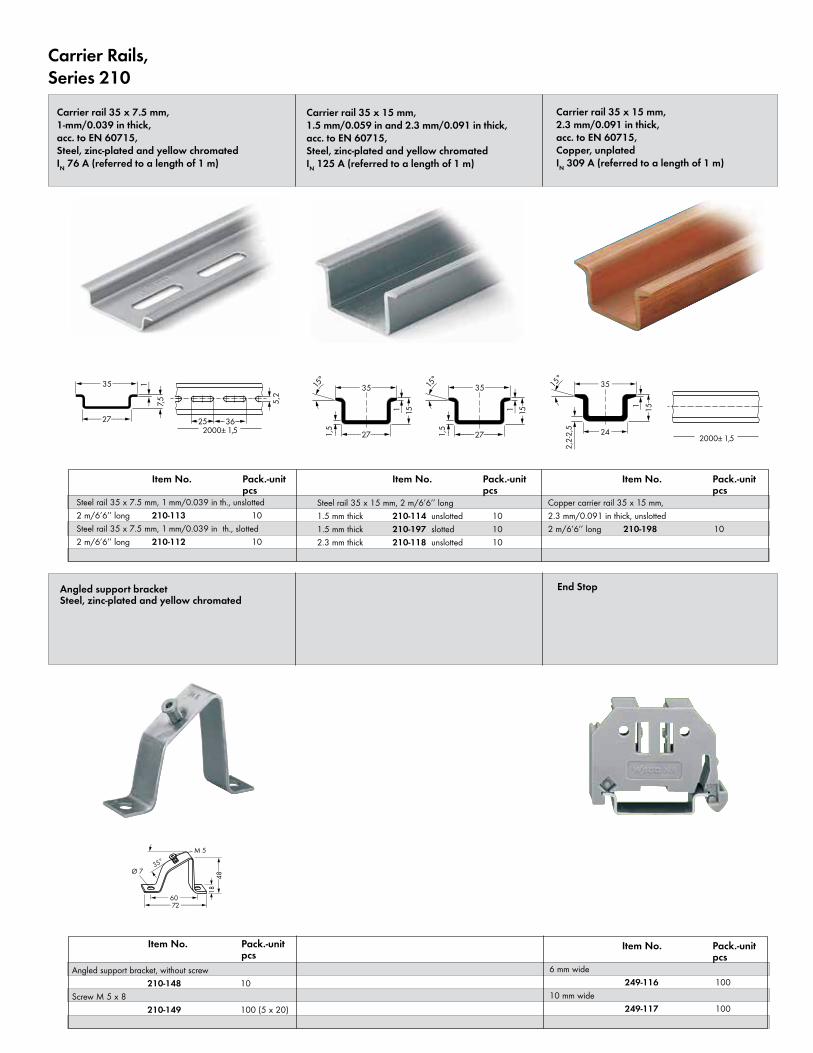
Carrier Rails,Series 210
<____ 35 ____>
<___ 27 ___> > 7,
5 <
> <
_1
<_ 36 _>(_25_)
> <
5,2
2000± 1,52000± 1,5
><
_ 1
_____>
<
<____ 35 ____>
<__ 24 __>
2,2-
2,5
(_15
_)
15°
Ø 7
M 5
35°
<___ 60 ___><______ 72 ______>
<__48
__>
>18
<
<____ 35 ____>
<___ 27 ___> 2000± 1,5
> <
_ 1
15°
(_15
_)
> <
_1,5
<____ 35 ____>
<___27 ___><_36_>(_25_)
><
5,2
2000± 1,5
><
_ 1
15°
(_15
_)
><_1,
5
Angled support bracket, without screw 210-148 10Screw M 5 x 8 210-149 100 (5 x 20)
Angled support bracketSteel, zinc-plated and yellow chromated
Steel rail 35 x 7.5 mm, 1 mm/0.039 in th., unslotted2 m/6’6’’ long 210-113 10Steel rail 35 x 7.5 mm, 1 mm/0.039 in th., slotted2 m/6’6’’ long 210-112 10
Copper carrier rail 35 x 15 mm, 2.3 mm/0.091 in thick, unslotted2 m/6’6’’ long 210-198 10
Steel rail 35 x 15 mm, 2 m/6’6’’ long 1.5 mm thick 210-114 unslotted 101.5 mm thick 210-197 slotted 102.3 mm thick 210-118 unslotted 10
Carrier rail 35 x 7.5 mm, 1-mm/0.039 in thick,acc. to EN 60715,Steel, zinc-plated and yellow chromatedIN 76 A (referred to a length of 1 m)
Carrier rail 35 x 15 mm, 2.3 mm/0.091 in thick,acc. to EN 60715,Copper, unplatedIN 309 A (referred to a length of 1 m)
Carrier rail 35 x 15 mm, 1.5 mm/0.059 in and 2.3 mm/0.091 in thick,acc. to EN 60715,Steel, zinc-plated and yellow chromatedIN 125 A (referred to a length of 1 m)
Item No. Pack.-unit pcs
Item No. Pack.-unit pcs
Item No. Pack.-unit pcs
Item No. Pack.-unit pcs
Item No. Pack.-unit pcs
6 mm wide 249-116 10010 mm wide 249-117 100
End Stop
**U with conditions of acceptability
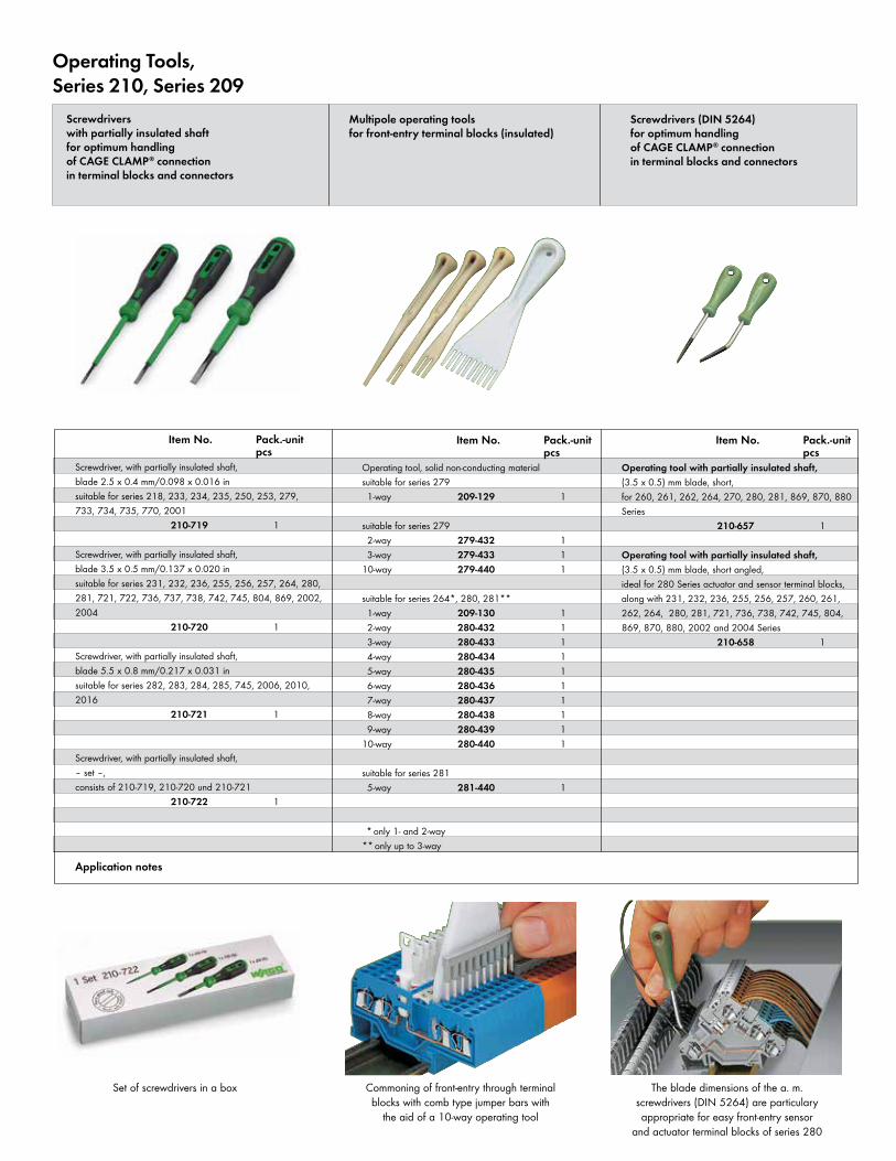
The blade dimensions of the a. m. screwdrivers (DIN 5264) are particulary appropriate for easy front-entry sensor
and actuator terminal blocks of series 280
Commoning of front-entry through terminal blocks with comb type jumper bars with
the aid of a 10-way operating tool
Set of screwdrivers in a box
Operating Tools,Series 210, Series 209
Screwdrivers (DIN 5264)for optimum handlingof CAGE CLAMP® connectionin terminal blocks and connectors
Operating tool with partially insulated shaft, (3.5 x 0.5) mm blade, short,for 260, 261, 262, 264, 270, 280, 281, 869, 870, 880 Series 210-657 1
Operating tool with partially insulated shaft, (3.5 x 0.5) mm blade, short angled,ideal for 280 Series actuator and sensor terminal blocks, along with 231, 232, 236, 255, 256, 257, 260, 261, 262, 264, 280, 281, 721, 736, 738, 742, 745, 804, 869, 870, 880, 2002 and 2004 Series 210-658 1
Screwdrivers with partially insulated shaftfor optimum handlingof CAGE CLAMP® connectionin terminal blocks and connectors
Multipole operating toolsfor front-entry terminal blocks (insulated)
Screwdriver, with partially insulated shaft, blade 2.5 x 0.4 mm/0.098 x 0.016 insuitable for series 218, 233, 234, 235, 250, 253, 279, 733, 734, 735, 770, 2001 210-719 1
Screwdriver, with partially insulated shaft, blade 3.5 x 0.5 mm/0.137 x 0.020 insuitable for series 231, 232, 236, 255, 256, 257, 264, 280, 281, 721, 722, 736, 737, 738, 742, 745, 804, 869, 2002, 2004 210-720 1
Screwdriver, with partially insulated shaft, blade 5.5 x 0.8 mm/0.217 x 0.031 insuitable for series 282, 283, 284, 285, 745, 2006, 2010, 2016 210-721 1
Screwdriver, with partially insulated shaft,– set –, consists of 210-719, 210-720 und 210-721 210-722 1
Operating tool, solid non-conducting materialsuitable for series 279 1-way 209-129 1
suitable for series 279 2-way 279-432 1 3-way 279-433 110-way 279-440 1
suitable for series 264*, 280, 281** 1-way 209-130 1 2-way 280-432 1 3-way 280-433 1 4-way 280-434 1 5-way 280-435 1 6-way 280-436 1 7-way 280-437 1 8-way 280-438 1 9-way 280-439 110-way 280-440 1
suitable for series 281 5-way 281-440 1
* only 1- and 2-way** only up to 3-way
Item No. Pack.-unit pcs
Item No. Pack.-unit pcs
Item No. Pack.-unit pcs
Application notes
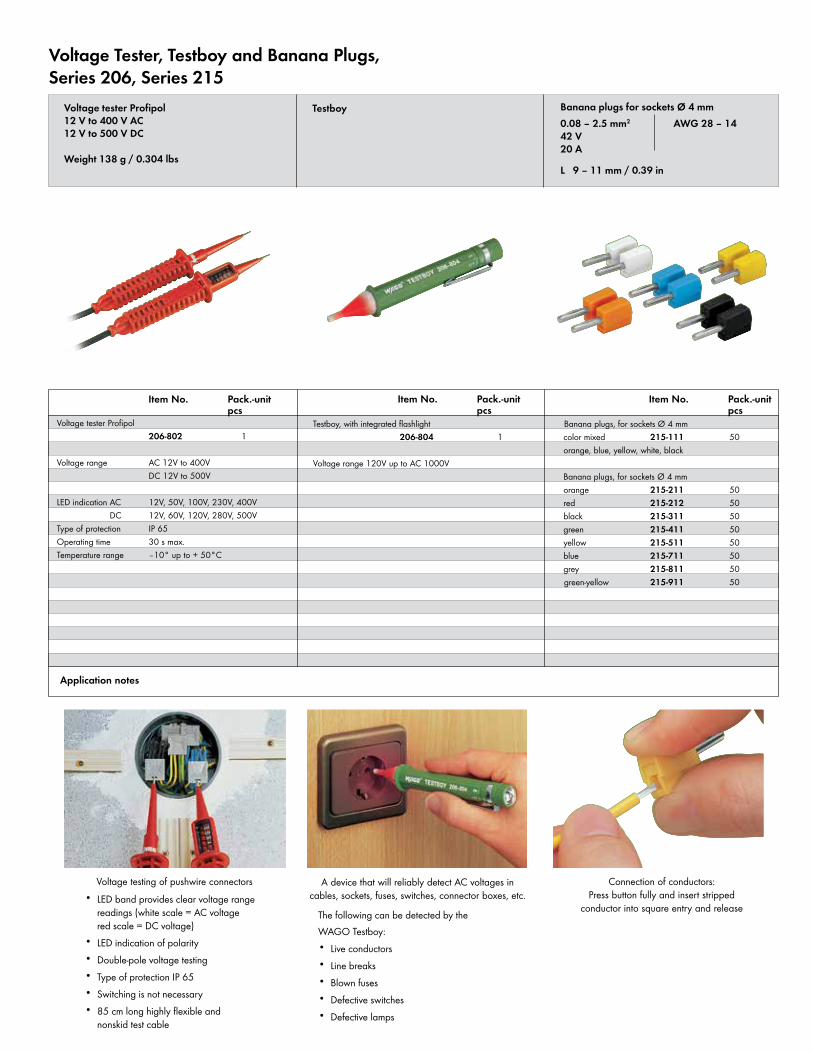
• LED band provides clear voltage range readings (white scale = AC voltage red scale = DC voltage)
• LED indication of polarity• Double-pole voltage testing• Type of protection IP 65• Switching is not necessary• 85 cm long highly flexible and
nonskid test cable
The following can be detected by theWAGO Testboy:• Live conductors• Line breaks• Blown fuses• Defective switches• Defective lamps
Connection of conductors:Press button fully and insert stripped
conductor into square entry and release
A device that will reliably detect AC voltages in cables, sockets, fuses, switches, connector boxes, etc.
Voltage testing of pushwire connectors
Voltage Tester, Testboy and Banana Plugs,Series 206, Series 215
TestboyVoltage tester Profipol12 V to 400 V AC12 V to 500 V DC
Weight 138 g / 0.304 lbs
Voltage tester Profipol 206-802 1
Voltage range AC 12V to 400V DC 12V to 500V
LED indication AC 12V, 50V, 100V, 230V, 400V DC 12V, 60V, 120V, 280V, 500V
Type of protection IP 65Operating time 30 s max.Temperature range –10° up to + 50°C
Testboy, with integrated flashlight 206-804 1
Voltage range 120V up to AC 1000V
Banana plugs, for sockets Ø 4 mmcolor mixed 215-111 50orange, blue, yellow, white, black
Banana plugs, for sockets Ø 4 mmorange 215-211 50red 215-212 50black 215-311 50green 215-411 50yellow 215-511 50blue 215-711 50grey 215-811 50green-yellow 215-911 50
Banana plugs for sockets Ø 4 mm 0.08 – 2.5 mm2 AWG 28 – 1442 V 20 A
L 9 – 11 mm / 0.39 in
Item No. Pack.-unit pcs
Item No. Pack.-unit pcs
Item No. Pack.-unit pcs
Application notes
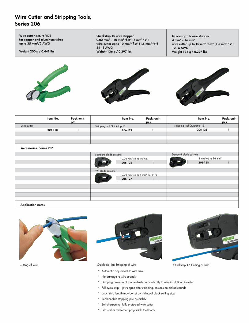
• Automatic adjustment to wire size• No damage to wire strands• Gripping pressure of jaws adjusts automatically to wire insulation diameter• Full cycle strip – jaws open after stripping, ensures no nicked strands• Exact strip length may be set by sliding of black setting stop• Replaceable stripping jaw assembly• Self-sharpening, fully protected wire cutter• Glass fiber reinforced polyamide tool body
Quickstrip 16 Cutting of wireQuickstrip 16: Stripping of wireCutting of wire
Wire Cutter and Stripping Tools,Series 206
Wire cutter acc. to VDEfor copper and aluminum wiresup to 35 mm2-/2 AWG
Weight 200 g / 0.441 lbs
Quickstrip 10 wire stripper0.02 mm2 – 10 mm2 “f-st“ (6 mm2 “s“)wire cutter up to 10 mm2 “f-st“ (1.5 mm2 “s“)34 - 8 AWGWeight 136 g / 0.297 lbs
Quickstrip 16 wire stripper4 mm2 – 16 mm2
wire cutter up to 10 mm2 “f-st“ (1.5 mm2 “s“)12 - 6 AWGWeight 136 g / 0.297 lbs
Wire cutter 206-118 1
Stripping tool Quickstrip 10 206-124 1
Standard blade cassette 0.02 mm2 up to 10 mm2
206-126 1 “V“ blade cassette 0.02 mm2 up to 4 mm2 for PTFE 206-127 1
Standard blade cassette 4 mm2 up to 16 mm2
206-128 1
Item No. Pack.-unit pcs
Stripping tool Quickstrip 16 206-125 1
Item No. Pack.-unit pcs
Item No. Pack.-unit pcs
Accessories, Series 206
Application notes
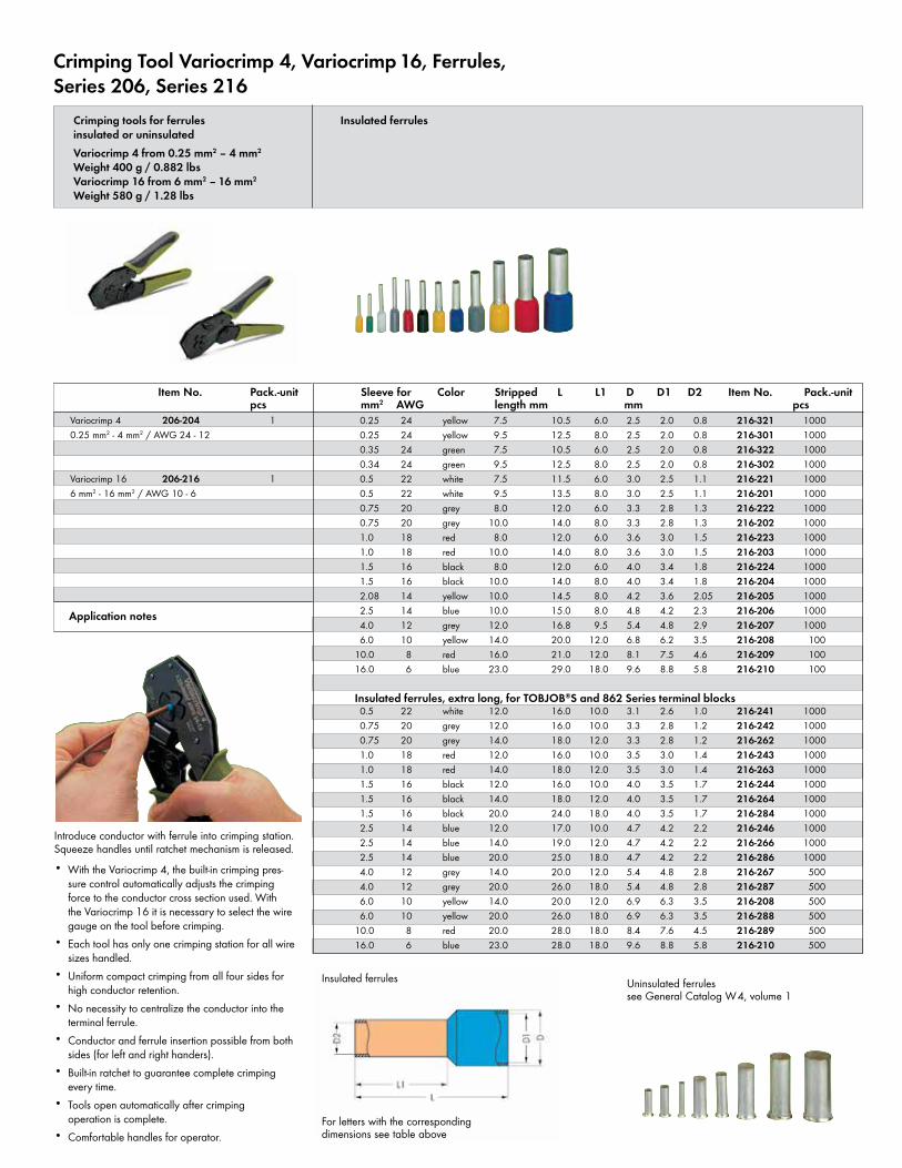
• With the Variocrimp 4, the built-in crimping pres-sure control automatically adjusts the crimping force to the conductor cross section used. With the Variocrimp 16 it is necessary to select the wire gauge on the tool before crimping.
• Each tool has only one crimping station for all wire sizes handled.
• Uniform compact crimping from all four sides for high conductor retention.
• No necessity to centralize the conductor into the terminal ferrule.
• Conductor and ferrule insertion possible from both sides (for left and right handers).
• Built-in ratchet to guarantee complete crimping every time.
• Tools open automatically after crimping operation is complete.
• Comfortable handles for operator.
Introduce conductor with ferrule into crimping station. Squeeze handles until ratchet mechanism is released.
Application notes
Item No. Pack.-unit pcs
Crimping Tool Variocrimp 4, Variocrimp 16, Ferrules,Series 206, Series 216
Variocrimp 4 206-204 10.25 mm2 - 4 mm2 / AWG 24 - 12
Variocrimp 16 206-216 16 mm2 - 16 mm2 / AWG 10 - 6
Insulated ferrules
For letters with the corresponding dimensions see table above
Uninsulated ferrules see General Catalog W4, volume 1
Crimping tools for ferrulesinsulated or uninsulatedVariocrimp 4 from 0.25 mm2 – 4 mm2 Weight 400 g / 0.882 lbsVariocrimp 16 from 6 mm2 – 16 mm2
Weight 580 g / 1.28 lbs
Insulated ferrules
0.25 24 yellow 7.5 10.5 6.0 2.5 2.0 0.8 216-321 1000 0.25 24 yellow 9.5 12.5 8.0 2.5 2.0 0.8 216-301 1000 0.35 24 green 7.5 10.5 6.0 2.5 2.0 0.8 216-322 1000 0.34 24 green 9.5 12.5 8.0 2.5 2.0 0.8 216-302 1000 0.5 22 white 7.5 11.5 6.0 3.0 2.5 1.1 216-221 1000 0.5 22 white 9.5 13.5 8.0 3.0 2.5 1.1 216-201 1000 0.75 20 grey 8.0 12.0 6.0 3.3 2.8 1.3 216-222 1000 0.75 20 grey 10.0 14.0 8.0 3.3 2.8 1.3 216-202 1000 1.0 18 red 8.0 12.0 6.0 3.6 3.0 1.5 216-223 1000 1.0 18 red 10.0 14.0 8.0 3.6 3.0 1.5 216-203 1000 1.5 16 black 8.0 12.0 6.0 4.0 3.4 1.8 216-224 1000 1.5 16 black 10.0 14.0 8.0 4.0 3.4 1.8 216-204 1000 2.08 14 yellow 10.0 14.5 8.0 4.2 3.6 2.05 216-205 1000 2.5 14 blue 10.0 15.0 8.0 4.8 4.2 2.3 216-206 1000 4.0 12 grey 12.0 16.8 9.5 5.4 4.8 2.9 216-207 1000 6.0 10 yellow 14.0 20.0 12.0 6.8 6.2 3.5 216-208 10010.0 8 red 16.0 21.0 12.0 8.1 7.5 4.6 216-209 10016.0 6 blue 23.0 29.0 18.0 9.6 8.8 5.8 216-210 100
Insulated ferrules, extra long, for TOBJOB®S and 862 Series terminal blocks 0.5 22 white 12.0 16.0 10.0 3.1 2.6 1.0 216-241 1000 0.75 20 grey 12.0 16.0 10.0 3.3 2.8 1.2 216-242 1000 0.75 20 grey 14.0 18.0 12.0 3.3 2.8 1.2 216-262 1000 1.0 18 red 12.0 16.0 10.0 3.5 3.0 1.4 216-243 1000 1.0 18 red 14.0 18.0 12.0 3.5 3.0 1.4 216-263 1000 1.5 16 black 12.0 16.0 10.0 4.0 3.5 1.7 216-244 1000 1.5 16 black 14.0 18.0 12.0 4.0 3.5 1.7 216-264 1000 1.5 16 black 20.0 24.0 18.0 4.0 3.5 1.7 216-284 1000 2.5 14 blue 12.0 17.0 10.0 4.7 4.2 2.2 216-246 1000 2.5 14 blue 14.0 19.0 12.0 4.7 4.2 2.2 216-266 1000 2.5 14 blue 20.0 25.0 18.0 4.7 4.2 2.2 216-286 1000 4.0 12 grey 14.0 20.0 12.0 5.4 4.8 2.8 216-267 500 4.0 12 grey 20.0 26.0 18.0 5.4 4.8 2.8 216-287 500 6.0 10 yellow 14.0 20.0 12.0 6.9 6.3 3.5 216-208 500 6.0 10 yellow 20.0 26.0 18.0 6.9 6.3 3.5 216-288 50010.0 8 red 20.0 28.0 18.0 8.4 7.6 4.5 216-289 50016.0 6 blue 23.0 28.0 18.0 9.6 8.8 5.8 216-210 500
Sleeve for Color Stripped L L1 D D1 D2 Item No. Pack.-unit mm2 AWG length mm mm pcs
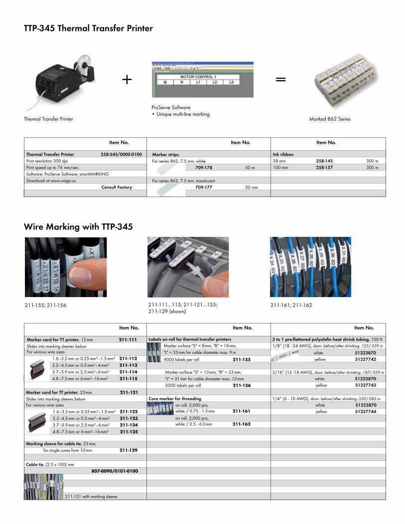
TTP-345 Thermal Transfer Printer
211-111...115; 211-121...125; 211-129 (shown)
211-155; 211-156
Thermal Transfer Printer 258-345/0000-0100Print resolution 300 dpiPrint speed up to 76 mm/sec.Software: ProServe Software; smartMARKINGDownload at www.wago.us Consult Factory
Marker stripsFor series 862, 7.5 mm, white 709-178 50 m For series 862, 7.5 mm, translucent 709-177 50 mm
211-121 with marking sleeve
Item No. Item No. Item No.
Ink ribbon38 mm 258-145 300 m100 mm 258-157 300 m
Item No. Item No. Item No.
3 to 1 pre-flattened polyolefin heat shrink tubing, 100 ft 1/8” (18 - 24 AWG), diam. before/after shrinking .125/.039 in
white 51223870 yellow 51227742
3/16” (12 -18 AWG), diam. before/after shrinking .187/.059 in white 51223870 yellow 51227743
1/4” (6 - 10 AWG), diam. before/after shrinking .250/.083 in white 51223870 yellow 51227744
Marker card for TT printer, 12 mm 211-111Slides into marking sleeves belowFor various wire sizes 1.6–3.2 mm or 0.25 mm²–1.5 mm² 211-112 2.2–4.5 mm or 0.5 mm²–4 mm² 211-113 3.7–5.9 mm or 2.5 mm²–6 mm² 211-114 4.8–7.5 mm or 6 mm²–16 mm² 211-115
Core marker for threading on roll, 2,000 pcs, white / 0.75 - 1.5 mm 211-161 on roll, 2,000 pcs, white / 2.5 - 6.0 mm 211-162
Wire Marking with TTP-345
Labels on roll for thermal transfer printers Marker surface "S" = 8 mm, "B" = 18 mm, "L" = 35 mm for cable diameter max. 9 m 9000 labels per roll 211-155
Marker surface "S" = 13 mm, "B" = 23 mm, "L" = 51 mm for cable diameter max. 12 mm 5000 labels per roll 211-156
Marker card for TT printer, 23mm 211-121Slides into marking sleeves belowFor various wire sizes 1.6–3.2 mm or 0.25 mm²–1.5 mm² 211-122 2.2–4.5 mm or 0.5 mm²–4 mm² 211-123 3.7–5.9 mm or 2.5 mm²–6 mm² 211-124 4.8–7.5 mm or 6 mm²–16 mm² 211-125
Marking sleeve for cable tie, 23 mm, for single cores from 10 mm 211-129
Cable tie, (2.5 x 100) mm 807-0090/0101-0100
Thermal Transfer Printer
ProServe Software• Unique multi-line marking
Marked 862 Series
211-161; 211-162
+ =
Notes

Notes
Notes
5126
1593
088
8-08
32/0
000-
0271
Prin
ted
in th
e U
nite
d St
ates
MexicoWAGO CorporationQueretaroTel. 001/800/309/5975 + 52/442/221/5946Fax + 52/442/221/5063 www.wago.mx
WAGO CorporationN120 W19129 Freistadt RoadGermantown, Wisconsin 53022Telephone: 800 / DIN Rail (346-7245)Fax: 262 / [email protected]
CanadaWAGO CorporationTel. 800/DIN Rail (346-7245)Fax 262/255-3232www.wago.ca


![jan 2012 · 2017-07-19 · phot 2" x 2.5" photo 2" x 2.5" C) PageMaps photo 2.5" x 2.5" photo 2.5" x 2.5" photo 2.5" x 2.5" photo 2" x 2.5" photo 2.5" x 2.5" C] PageMaps photo 2.5"](https://img.pdfslide.us/doc/110x75/5f4cb42409b5fa18f7093d11/jan-2012-2017-07-19-phot-2-x-25-photo-2-x-25-c-pagemaps.jpg)