Embed Size (px)
DESCRIPTION
Electrical Installation of Facilities LPG CNG
Citation preview

ELECTRICAL INSTALLATION OF FACILITIESFOR THE STORAGE AND DISPENSING OF
LPG AND CNG AUTOMOTIVE FUELSAT VEHICLE REFUELLING STATIONS
November 2003
Published byENERGY INSTITUTE, LONDON
The Energy Institute is a professional membership body incorporated by Royal Charter 2003Registered charity number 1097899
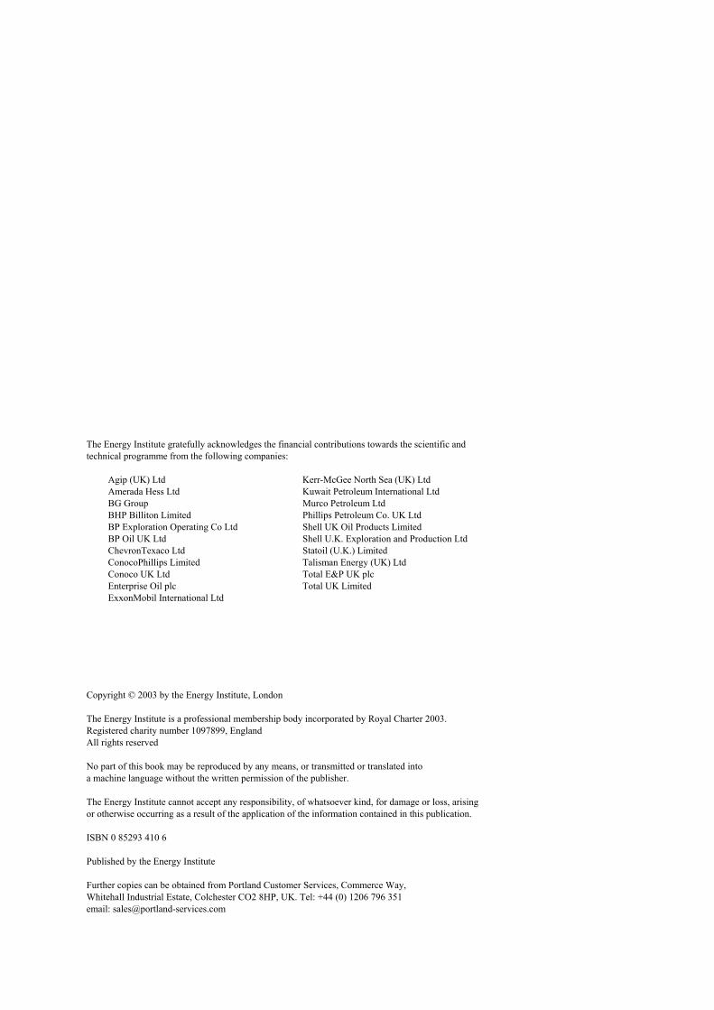
The Energy Institute gratefully acknowledges the financial contributions towards the scientific andtechnical programme from the following companies:
Agip (UK) LtdAmerada Hess LtdBG GroupBHP Billiton LimitedBP Exploration Operating Co LtdBP Oil UK LtdChevronTexaco LtdConocoPhillips LimitedConoco UK LtdEnterprise Oil plcExxonMobil International Ltd
Kerr-McGee North Sea (UK) LtdKuwait Petroleum International LtdMurco Petroleum LtdPhillips Petroleum Co. UK LtdShell UK Oil Products LimitedShell U.K. Exploration and Production LtdStatoil (U.K.) LimitedTalisman Energy (UK) LtdTotal E&P UK plcTotal UK Limited
Copyright © 2003 by the Energy Institute, London
The Energy Institute is a professional membership body incorporated by Royal Charter 2003.Registered charity number 1097899, EnglandAll rights reserved
No part of this book may be reproduced by any means, or transmitted or translated intoa machine language without the written permission of the publisher.
The Energy Institute cannot accept any responsibility, of whatsoever kind, for damage or loss, arisingor otherwise occurring as a result of the application of the information contained in this publication.
ISBN 0 85293 410 6
Published by the Energy Institute
Further copies can be obtained from Portland Customer Services, Commerce Way,Whitehall Industrial Estate, Colchester CO2 8HP, UK. Tel: +44 (0) 1206 796 351email: [email protected]

iii
CONTENTS
Page
Foreword . . . . . . . . . . . . . . . . . . . . . . . . . . . . . . . . . . . . . . . . . . . . . . . . . . . . . . . . . . . . . . . . . . . . . . . . . . . . . . iv
Acknowledgements . . . . . . . . . . . . . . . . . . . . . . . . . . . . . . . . . . . . . . . . . . . . . . . . . . . . . . . . . . . . . . . . . . . . . . . v
1 Introduction . . . . . . . . . . . . . . . . . . . . . . . . . . . . . . . . . . . . . . . . . . . . . . . . . . . . . . . . . . . . . . . . . . . . . . . . . 1
2 Consultation . . . . . . . . . . . . . . . . . . . . . . . . . . . . . . . . . . . . . . . . . . . . . . . . . . . . . . . . . . . . . . . . . . . . . . . . 2
3 Design standards . . . . . . . . . . . . . . . . . . . . . . . . . . . . . . . . . . . . . . . . . . . . . . . . . . . . . . . . . . . . . . . . . . . . . 3
4 Area classification and separation distances . . . . . . . . . . . . . . . . . . . . . . . . . . . . . . . . . . . . . . . . . . . . . . 44.1 General . . . . . . . . . . . . . . . . . . . . . . . . . . . . . . . . . . . . . . . . . . . . . . . . . . . . . . . . . . . . . . . . . . . . . . . . . . 44.2 Dispenser zoning . . . . . . . . . . . . . . . . . . . . . . . . . . . . . . . . . . . . . . . . . . . . . . . . . . . . . . . . . . . . . . . . . . 44.3 Separation distances . . . . . . . . . . . . . . . . . . . . . . . . . . . . . . . . . . . . . . . . . . . . . . . . . . . . . . . . . . . . . . . . 4
5 Electrical supplies . . . . . . . . . . . . . . . . . . . . . . . . . . . . . . . . . . . . . . . . . . . . . . . . . . . . . . . . . . . . . . . . . . . . 5
6 Selection, installation and location of equipment . . . . . . . . . . . . . . . . . . . . . . . . . . . . . . . . . . . . . . . . . . . 6
7 Isolation and switching . . . . . . . . . . . . . . . . . . . . . . . . . . . . . . . . . . . . . . . . . . . . . . . . . . . . . . . . . . . . . . . . 7
8 Overcurrent protection and discrimination . . . . . . . . . . . . . . . . . . . . . . . . . . . . . . . . . . . . . . . . . . . . . . . 8
9 Protection against electric shock . . . . . . . . . . . . . . . . . . . . . . . . . . . . . . . . . . . . . . . . . . . . . . . . . . . . . . . . 9
10 Earthing and bonding . . . . . . . . . . . . . . . . . . . . . . . . . . . . . . . . . . . . . . . . . . . . . . . . . . . . . . . . . . . . . . . . 11
11 Wiring systems . . . . . . . . . . . . . . . . . . . . . . . . . . . . . . . . . . . . . . . . . . . . . . . . . . . . . . . . . . . . . . . . . . . . . 12
12 Ducts and manholes . . . . . . . . . . . . . . . . . . . . . . . . . . . . . . . . . . . . . . . . . . . . . . . . . . . . . . . . . . . . . . . . . 14
13 Force ventilated ducts and manholes . . . . . . . . . . . . . . . . . . . . . . . . . . . . . . . . . . . . . . . . . . . . . . . . . . . 15
14 Labels and warning notices . . . . . . . . . . . . . . . . . . . . . . . . . . . . . . . . . . . . . . . . . . . . . . . . . . . . . . . . . . . 16
15 Inspection and testing . . . . . . . . . . . . . . . . . . . . . . . . . . . . . . . . . . . . . . . . . . . . . . . . . . . . . . . . . . . . . . . . 18
Annex A A.1 Hazardous area zoning . . . . . . . . . . . . . . . . . . . . . . . . . . . . . . . . . . . . . . . . . . . . . . . . . . . . . . . . . . . . . . . 20A.2 Separation distances . . . . . . . . . . . . . . . . . . . . . . . . . . . . . . . . . . . . . . . . . . . . . . . . . . . . . . . . . . . . . . . . . 20
Annex B - References . . . . . . . . . . . . . . . . . . . . . . . . . . . . . . . . . . . . . . . . . . . . . . . . . . . . . . . . . . . . . . . . . . . . 22

iv
FOREWORD
The guidance included in this publication has been prepared by the Service Station Panel of the Energy Institutein consultation with a wide range of industry stakeholders, with the encouragement and support of the UK Healthand Safety Executive (HSE).
The guidance is intended to assist those in the UK comply with the statutory Electricity at Work Regulations (1989)and petroleum storage legislation, with regard to electrical design and installation relating to the storage anddispensing of LPG and/or CNG as an automotive fuel.
The guidance includes key features of the electrical provisions of APEA/IP Guidance for the design, construction,modification and maintenance of petrol filling stations.
The guidance in this publication has primarily been prepared for use within the UK. However, those installing suchfacilities elsewhere may benefit from considering the guidance included herein.
The Energy Institute cannot accept responsibility, of whatsoever kind, for damage or loss, arising or otherwiseoccurring as a result of the application of the information contained in this publication.
Suggested revisions are invited and should be submitted to the Technical Department, the Energy Institute, 61 NewCavendish Street, London W1G 7AR, UK.

v
ACKNOWLEDGEMENTS
This publication was prepared at the request of the Energy Institute’s Service Station Panel by John Dallimore (JohnDallimore & Partners) and Terry Hedgeland (Independent Consultant). It was subsequently reviewed byrepresentatives of the following companies and organisations:
Association of Petroleum and Explosives Administration (APEA)Association of UK Oil Independents (AUKOI)Berry & CoBPChevronTexaco LtdConocoPhillipsElectrical Contractors Association (ECA)Esso Petroleum Company LtdJ & R GilbertHealth & Safety ExecutiveLP Gas Association (LPGA)National Inspection Council for Electrical Installation Contracting (NICELC)Petrol Retailers Association (PRA)Petroleum Equipment Installers & Maintenance Federation (PEIMF)SelectShell UK LtdTesco Stores LimitedTotal UK
The Association for Petroleum and Explosives Administration (APEA) is thanked for agreeing to the reproductionof certain sections of text taken directly from APEA/IP Guidance for the design, construction, modification andmaintenance of petrol filling stations.
1
1
INTRODUCTION
Liquefied Petroleum Gas (LPG) for use in motorvehicles, generally known as Autogas, is beingencouraged in the UK as an alternative fuel because ofits cleaner burning characteristics and environmentalbenefits. Autogas may be sold alongside other motorfuels at vehicle refuelling stations or at dedicatedAutogas stations.
Compressed Natural Gas (CNG) similarly isavailable in the UK.
In the UK all vehicle refuelling stations storing anddispensing LPG or CNG are covered by the Dangerous
Substances and Explosive Atmospheres Regulations2002 (DSEAR), whether dedicated to those fuels aloneor in combination with petroleum. Other Health andSafety legislation applies in any event. Where LPG orCNG is installed at a vehicle refuelling station that ispresently subject to petroleum licensing, the PetroleumEnforcement Authority (PEA) can attach conditionswhich relate to LPG or CNG, since the storage anddispensing of those fuels may impact with the storageand dispensing of petroleum.

2
2
CONSULTATION
The facilities needed at the LPG/CNG/petroleumrefuelling station should be ascertained as accurately aspossible by consultation between the client and, asappropriate, the operator (if not the client), the architect,the consultant, the main contractor, the electricalcontractor, the fuel storage and dispensing equipmentmanufacturer and installer, the cathodic protectioncontractor, the static protection contractor, the lightningprotection contractor, the fire insurer, the electricitysupplier, the enforcing authority and any other publicauthority concerned.
Documents should then be prepared and circulatedfor final written agreement, or comment, showing:
a) details of the installation proposed, relatedextraneous-conductive-parts (e.g. tanks, pipeworkand structures) and additional electrical bonding;
b) the accommodation and structural provisionsrequired for the equipment (e.g. siting ofswitchgear and metering, central control point,emergency switching, etc.) and the provision oflighting and adequate access of all equipment;
c) chases, ducts, manholes, draw-chambers, conduits,channels, trunking and other provisions requiredfor electrical wiring.

3
3
DESIGN STANDARDS
This guidance on electrical installations incorporatesand, where appropriate, supersedes earlierrecommendations contained in publications from IP,APEA, LPGA and other sources.
The design and installation should, in general,comply with the electrical provisions of APEA/IPGuidance for the design, construction, modification andmaintenance of petrol filling stations. Key features ofthat publication and additional or alternative provisions
for LPG and CNG installations are identified further inthis publication, which should be used in conjunctionwith Guidance for the design, construction,modification and maintenance of petrol filling stations.
For guidance on non-electrical aspects relating toAutogas, reference may be made to the LPGA suite ofCodes of Practice which cover most aspects of storageand transportation.

4
4
AREA CLASSIFICATION ANDSEPARATION DISTANCES
4.1 GENERAL
Hazardous area zoning for LPG/CNG installations isbased on the fundamental criteria given in BS EN60079-10:2003 for Zones 0, 1 or 2 as applied topetroleum and other potentially explosive products.
Electrical equipment installed in a zoned area mustbe appropriately explosion-protected for installation inthat area.
By implication, an area which is not classified asZone 0, 1 or 2 is deemed to be non-hazardous withrespect to the selection of electrical apparatus.
Descriptions of hazardous area zones are given inAnnex A. Details of hazardous area zoning around LPGstorage vessels, pumps and delivery vehicle connectionsare given in IP Model Code of Safe Practice Part 15Area classification code for installations handlingflammable fluids. LPGA Code of Practice Part 1, givesseparation distances between LPG vessels and buildingsand other items of equipment.
Where provisions for storage and dispensing LPGor CNG are to be added to a site dispensing petroleum,and the zoning for these fuels may overlap with zoningof petroleum-related equipment, care must be taken tosatisfy the more extensive zoning requirements for theLPG or CNG.
4.2 DISPENSER ZONING
For consistency with other fuel dispensers (e.g.complying with BS 7117) LPG/CNG dispensers should
be considered as petrol dispensers with stage 2 vapourrecovery but without the vent air separator. Generalzoning requirements for petrol dispensers are given inGuidance for the design, construction, modification andmaintenance of petrol filling stations.
As with petrol dispensers the zoning within andimmediately above the housing of an LPG/CNGdispenser will depend on the internal construction (e.g.employing vapour barriers). Knowledge of thedispenser internal zoning is essential.
A manufacturer/importer or someone marketing adispenser should supply with the unit a diagramshowing the zoned areas in and around the unit. Thisshould be available at the design stage.
An alternative is to apply the area classification forAutogas dispensers shown in LPGA Code of Practice20.
4.3 SEPARATION DISTANCES
In order to ensure clearance from an item of LPGequipment to other items of equipment, buildings orpotential sources of ignition, guidance on separationdistances has been established.
Tables 1 and 2 in Annex A provide guidance onseparation distances between a range of componentsand other objects.

5
5
ELECTRICAL SUPPLIES
Electrical supplies for the LPG/CNG installation shouldcomply with the relevant provisions of Section 14.3 ofGuidance for the design, construction, modification andmaintenance of petrol filling stations.
Essential features to be considered include thefollowing.
— A plan of the LPG/CNG installation should beappended to the existing site plan displayed withinthe premises.
— The LPG/CNG installation should not be installedbelow overhead conductors (electricity, telephonelines, etc.), except where protected overhead by anearthed metallic canopy as detailed in Guidance forthe design, construction, modification andmaintenance of petrol filling stations.
— At an existing vehicle refuelling station, an
assessment should be made of the incomingelectricity supply and main switchgear with regardto its ability to accommodate the proposedLPG/CNG installation.
— On a stand-alone LPG/CNG site, the specificrecommendations of Section 14.3 of Guidance forthe design, construction, modification andmaintenance of petrol filling stations apply in full.
— A risk assessment should be carried out by thedesigner to determine the need for lightningprotection of structures at the LPG/CNG location.
— Where protective multiple earthing (PME) exists asthe means of earthing the site, particular attentionshould be given to the possible effect of divertedneutral currents passing into hazardous zones viametalwork and protective conductors.

6
6
SELECTION, INSTALLATION ANDLOCATION OF EQUIPMENT
The following features relating to the selection,installation and location of equipment include asummary of the provisions of Sections 14.4 and 14.5 ofGuidance for the design, construction, modification andmaintenance of petrol filling stations, which should beapplied to installations for dispensing LPG or CNG toroad vehicles.
— Equipment should be certified to an explosionprotection standard suitable for the zone in whichit is to be used – only equipment constructed tocomply with The Equipment and ProtectiveSystems Intended for Use in Potentially ExplosiveAtmospheres Regulations 1996, or an appropriateBritish, harmonised European, equivalentinternational standard and with ATEX should beused.
— Associated equipment installed in a non-hazardousarea must not have an adverse effect on theexplosion-protection concept of the equipmentlocated in the hazardous area.
— Equipment, which when operating displaces oringests air, (e.g. vacuum cleaning equipment withextended hose, car wash, warm air central heatingor air compressors) should not be installed whereit may affect, or be affected by, a potentiallyexplosive atmosphere.
— In addition to an electrical enclosure being suitably
explosion-protected, protection against adverseenvironmental conditions, particularly the ingressof moisture or water, must be provided by anenclosure having an appropriate 'Index ofProtection' (IP number).
— Where a tank and pipework system incorporateplastics components with isolated metal parts,protection against static electricity may berequired. Detailed provisions for this form ofprotection are given in 14.4.6 of Guidance for thedesign, construction, modification andmaintenance of petrol filling stations.
— Where cathodic protection of LPG/CNG tanks andpipework is required, comprehensive guidance onthe subject is given in IP Guidance on cathodicprotection of underground steel storage tanks andsteel pipework at petrol filling stations.
— Any LPG/CNG dispenser should be covered by thesite loudspeaker warning system. The loudspeakerwarning system should be separate from thedispensers and not controlled by the emergencyswitching system.
— Lighting of the LPG/CNG compound andassociated road tanker delivery area should bedesigned to ensure an illuminance of 100 lux atground level in these areas, allowing for a deliveryvehicle to be in position.

7
7
ISOLATION AND SWITCHING
The following features relating to isolation andswitching include a summary of the provisions ofSection 14.6 of Guidance for the design, construction,modification and maintenance of petrol filling stations.
— Means of isolation and switching must complywith Regulation 12 of the Electricity at WorkRegulations 1989 (as amended).
— For stand-alone LPG/CNG installations, theprovisions of Section 14.6 of Guidance for thedesign, construction, modification andmaintenance of petrol filling stations apply ingeneral.
— Devices for the isolation and control of LPGelectrical equipment should interruptsimultaneously all live poles, including the neutral.Other than isolating devices adjacent to pumps,which must be suitably explosion- and ingress-protected, devices for isolation and control shouldbe located in a non-hazardous area.
— Devices for isolation for electrical maintenancepurposes must have locking-off facilities. Fusecarriers are not acceptable.
— An emergency switching device should beprovided at each entrance/exit of the LPG/CNGcompound.
— Where a tank and fill point are installedunderground, an emergency switching device mustbe provided in a non-hazardous area adjacent to thetanker stand. This device may be within a drivercontrolled delivery (DCD) facility.
— The electrical circuits, other than any incorporatingcertified intrinsically safe equipment, to theLPG/CNG pump(s) and dispenser(s) should bearranged such that, on the operation of anemergency switch on the refuelling station, theLPG/CNG pump(s) and dispenser(s) and also thepetrol pumps and dispensers are ALL electricallyde-energised – the supply should be capable ofbeing reset only from inside the console area.

8
8
OVERCURRENT PROTECTIONAND DISCRIMINATION
The following features of overcurrent protection anddiscrimination include a summary of the provisions ofSection 14.7 of Guidance for the design, construction,modification and maintenance of petrol filling stations,which should be applied to installations for dispensingLPG or CNG to road vehicles.
— Discrimination of operation of series devices mustbe ensured for both fault current and overloadprotection.
— For residual current devices in series the supplyside device should be time-delayed to ensurediscrimination of operation.
— Every fault current device and residual currentdevice should have fault breaking capacity not lessthan the prospective fault level at its point ofinstallation.
— If separate devices are employed for fault currentand overload protection, their characteristicsshould be co-ordinated and each device labelled toshow its function.
— Each dispenser circuit (including integral lightingand ancillary circuits other than data and signallingcircuits not liable to overload or fault currents)should be individually protected against overloadand fault currents by a suitably rated multi-polecircuit breaker arranged to break all liveconductors including the neutral.
— If the circuit breaker is suitable for, and is providedas, a means of isolation it must have locking-offfacilities.

9
9
PROTECTION AGAINST ELECTRICSHOCK
The following features of protection against electricshock include a summary of the provisions of Section14.8 of Guidance for the design, construction,modification and maintenance of petrol filling stations,which should be applied to installations for dispensingLPG or CNG to road vehicles. — Protection against indirect contact should be
provided by earthed equipotential bonding andautomatic disconnection of supply or by use ofequipment of Class II construction (doubleinsulated) where it is under effective supervision innormal use.
— Where bonding is required, it must be providedlocally across the gap between the items to bebonded, regardless of bonding elsewhere.
— The automatic disconnection of supply to forecourtcircuits must not exceed 100 ms in the event of anearth fault.
— Where a single device provides protection againstoverload, fault current and indirect contact it mustbreak phase and neutral conductors, i.e. a multi-pole circuit breaker (CB) or residual current circuitbreaker with overcurrent protection (RCBO) isrequired - fuses must not be used.
— Extra-low voltage data and other systems notintrinsically safe should be provided by theinstallation of SELV circuits (separated extra-lowvoltage) supplied via a BS 3535 (BS EN 60742)
safety isolating transformer or equivalent safetysource - neither the live parts nor the exposedmetalwork of the SELV circuit should be earthed.
— Where a vehicle refuelling station installation ispart of a TT system, or where earthingarrangements are such that disconnection timescannot be achieved with overcurrent protectivedevices, residual current devices (RCDs) will berequired to facilitate automatic disconnection ofsupply.
— It is inappropriate to provide a single 'front end'RCD at the main switch position as the sole meansof earth fault disconnection for the installation.
— Circuits will usually be RCD protected individuallyin order to satisfy site operational requirements - inany event an RCD incorporated in a circuit servinga hazardous area should be independent of RCDsprotecting non-hazardous area circuits.
— If RCDs are connected in series, discrimination ofoperation of a load side device must be ensured byincorporating a supply side device having asuitable time-delay.
— For each RCD the leakage current of the associatedcircuit must not exceed 25 % of the rated residualcurrent of the RCD.
— Where mineral insulated cable having circuitconductors of 2,5 mm2 or less cross-sectional area

ELECTRICAL INSTALLATION OF FACILITIES FOR THE STORAGE AND DISPENSINGOF LPG AND CNG AUTOMOTIVE FUELS AT VEHICLE REFUELLING STATIONS
10
(csa), installed to meet specified conditions, isprotected by a circuit breaker complying withBS 3871 or BS EN 60898 and having a rating of32A or less, the automatic disconnectionrequirements for indirect contact shock protectionare deemed to be met.

11
10
EARTHING AND BONDING
The general guidance on earthing and bonding inSection 14.8 of Guidance for the design, construction,modification and maintenance of petrol filling stationsshould be applied to LPG/CNG installations.
Particular attention should be given to thefollowing.
— Where the site earthing system is connected to aPME terminal, a risk assessment should be carriedout to determine any possible adverse effects onthe LPG/CNG installation – where the metalworkof the LPG/CNG installation is cathodicallyprotected and employs isolating joints, the effectsof diverted neutral currents should be obviated.
— An earthing bar or terminal should be provided inevery enclosure of electrical equipment, other thanequipment specified as having Class 2construction.
— Care should be taken to ensure that the earthingarrangements for data cable screening do notintroduce potentially dangerous levels of ignitionenergy into a hazardous area - generally screeningshould be earthed at one point only.
— Provision should be made for the electricalconnection of LPG/CNG road tankers to themetalwork of the LPG/CNG system. The terminalor other provision, which must not be located in a
manhole or other hazardous area location, shouldbe suitable for making a bond to the tanker prior tothe commencement of, and until completion of, thefinal transfer operation. Where the LPG/CNG tankand pipe metalwork are cathodically protected, careshould be taken to ensure that provision of thetanker bonding point, when in use, does not bridgethe cathodic protection arrangements.
— Where an LPG or CNG electrical installation doesnot share a site with facilities for dispensing ofpetroleum or other fuels, an all-insulated testsocket for measuring earth loop impedance andprospective fault current should be installed at theorigin of the installation in conjunction with themain earth terminal test link - a suitably labelledinsulated protective conductor which is segregatedfrom the earthing arrangements within theinstallation should connect the earth terminal of thetest socket to the earthing conductor side of themain earth terminal test link.
— The test socket and its related all-insulated deviceincorporating isolation and overcurrent protectionshould comply with 14.4.4 of Guidance for thedesign, construction, modification andmaintenance of petrol filling stations. The meansof isolation should be capable of being locked andshould be provided with a label identifying itspurpose (see Section 14 for label details).

12
11
WIRING SYSTEMS
The following features of wiring systems include asummary of the provisions of Section 14.9 of Guidancefor the design, construction, modification andmaintenance of petrol filling stations, which should beapplied to installations for dispensing LPG or CNG toroad vehicles.
— All conductors (other than prescribed bondingbridges) having a CSA of 16 mm2 or less should becopper.
— Every protective conductor not forming part of acable or cable enclosure should be identifiedthroughout by green/yellow insulating covering.
— Contact between cables of intrinsically safe (IS)circuits and those which are non-intrinsically safeshould be prevented - preferably running the IScables in a non-conducting duct or pipe reservedsolely for that purpose.
— IS conductors must not be run in the samemulticore cable with non-IS circuit conductors -nor in the same enclosure or duct with non-IScircuits unless segregated by an earthed metalscreen or shield.
— Particular attention should be given to theconstruction of cables for IS circuits so as to ensurethat they are not damaged by the installation ofother cables sharing a common duct.
— Care should be taken to ensure that metallic
screening or sheaths of IS circuit cables are earthedat one point only and do not constitute an earthpath for electrical fault current or currents whichcould adversely affect transmitted data.
— Where extra-low voltage circuits (ELV = not morethan 50 Va.c., 120 Vd.c.) are contained in the sametrunking, duct or multicore cable as higher voltagecircuits, the latter must be provided with an earthedmetallic screen or sheath with a current carryingcapacity equivalent to that of the higher voltagecores. Alternatively, the conductors of an ELVsystem should be insulated individually orcollectively for the highest voltage present on otherconductors in the same enclosure. The highervoltage grade insulation should be appliedthroughout the ELV system.
— All cables installed underground or in site-formedducts should be laid at a depth of not less than500 mm or be otherwise protected againstmechanical damage.
— Cables laid directly in the ground should beprotected by cable covers or identified by suitablemarking tape.
— Cables laid or drawn into ducts should be of suchconstruction that that they are not liable to bedamaged by the drawing in or withdrawal of othercables.
— In any location available for vehicular access,

ELECTRICAL INSTALLATION OF FACILITIES FOR THE STORAGE AND DISPENSINGOF LPG AND CNG AUTOMOTIVE FUELS AT VEHICLE REFUELLING STATIONS
13
cables, trunking or other electrical enclosuresshould be positioned or additionally protected to aheight of 1,5 m so that they are unlikely to bedamaged by moving vehicles.
— The protective conductor for every circuitsupplying low voltage equipment (e.g. 230 Vpower) in a hazardous area should be provided bymeans of an integral cable core in addition to anyprotective function provided by a cable sheath orarmour.
— Types of cable are specified, mineral insulatedcable terminated with earth tail pots and glandsapproved for Zone 1 or Zone 2, as appropriate,being preferred.
— Steel wire armoured cables terminated with glandsapproved for Zone 1 or Zone 2, as appropriate, inhazardous areas may be employed subject to theinstallation of earth tag washers at the cable glandsin non-hazardous areas - a lugged cable connection(cable same csa as related phase conductor,minimum 2,5 mm2) being provided between the
earth tag washer and enclosure earthing bar orterminal.
— Alternatively, steel wire braided cable havinghydrocarbon resistant outer covering may beemployed if it is terminated in shrouded glandswhich provide mechanically and electrically soundanchorage for the steel wire braid and which aresuited to the zoning of the hazardous area tomaintain the integrity of the explosion protectionconcept.
— Other cable is acceptable only if it forms part of anintrinsically safe (IS) circuit and, if multicore,contains only IS circuits and is not run with othercircuits in a common duct unless the other circuitsare separated from the IS circuit(s) by a suitableearthed metallic screen or barrier.
— Within Zone 0 hazardous areas the previouslydescribed cables are acceptable providing theyform part of a system certified as intrinsically safefor Zone 0, or pass unbroken through the Zone.

14
12
DUCTS AND MANHOLES
The following are general features applicable to ductsand manholes of LPG/CNG installations.
— Duct systems for underground cables in hazardousareas must be designed and constructed tominimise the possibility of fuel or vapour enteringother areas or accumulating within the duct system.
— Electric cables should not be enclosed in the sameduct as LPG/CNG pipelines.
— Ducts must be impervious to water and fuelproducts.
— Manholes, cable chambers and draw boxes shouldbe water and fuel tight, constructed of GRP,polythene or engineering brick.
— Comprehensive guidance on the provision ofunderground cable duct systems is given in
Guidance for the design, construction,modification and maintenance of petrol fillingstations.
— Other than for duct systems which are suction fanvented, it is of the utmost importance that, beforeany fuel is brought on site, duct terminations areadequately sealed in underground chambers, atdispensing equipment, the central control point andparticularly where ducts pass from hazardous tonon-hazardous areas.
— Sealing should be achieved with suitablecompound or other material resistant tohydrocarbon products and their vapours, all spareand unused ducts first being fitted with taperedhardwood plugs - cable pits, trenches andmanholes should not be sand filled and/orscreeded.

15
13
FORCE VENTILATED DUCTSAND MANHOLES
Where a force ventilated system is employed to avoida build-up of vapour in ducts and manholes associatedwith the LPG/CNG system, the following points shouldbe noted.
— Guidance for the design, construction,modification and maintenance of petrol fillingstations does not contain guidance on this subject.
— The ventilation unit should not be controlled by theemergency switching arrangements for the pumpsystems.
— The ventilation unit must be certified for use inZone 1.
— Ventilated ducts and manholes should be totallysegregated from all other ducts and manholes.
— The ventilated ducts must not be sealed orobstructed in any way.
— Where the ventilation system incorporates a ventpipe, the pipe should be treated as a petroleum ventpipe without vapour recovery for the purposes ofzoning.
— Electrical equipment, including cable, must not bemounted on the vent pipe.

16
14
LABELS AND WARNING NOTICES
The following features of wiring systems include asummary of the provisions of Section 14.9.8 ofGuidance for the design, construction, modification andmaintenance of petrol filling stations, which should beapplied to installations for dispensing LPG or CNG toroad vehicles.
— Labels should be of a permanent nature, e.g.'sandwich' plastics material resistant to adverseeffects of weather and hydrocarbons, so that paintfilling of engraved characters is not required - useshould be made of contrasting colours, e.g. blackagainst white background, white against redbackground, etc. as appropriate.
— Labels and their lettering should be sized inproportion to equipment on which they are to bemounted and should be securely fixed.
— Where equipment must not be drilled, e.g.explosion-protected or watertight apparatus, asuitable adhesive should be used, the maker’srecommendations on preparation of surfaces, etc.being fully observed.
— Where adjacent equipment has interchangeableremovable covers, labels should not be fitted tocovers but should be in fixed positions.
— If any labels are provided to warn of a significantrisk to health and safety, or are required under anyother relevant law, they must comply with theHealth and Safety (Safety Signs and Signals)Regulations 1996.
— A conspicuous, durable and legible notice must befitted adjacent to the main isolating switch for therefuelling station electrical installation and at anyequipment at which cathodically protectedmetalwork is simultaneously accessible with otherearthing arrangements, bearing the words: "ALLOR PART OF THE TANKS AND PIPEWORKA T T H I S S I T E H A S C A T H O D I CPROTECTION".
— The isolating device for the test socket at the originof the installation should be labelled "THISDEVICE IS NOT ISOLATED BY THE MAINISOLATING SWITCH AND MUST REMAINLOCKED IN THE OFF POSITION WHEN NOTBEING USED FOR TEST PURPOSES".
— On all luminaires within a hazardous area, themaximum permissible lamp wattage should beclearly indicated by a permanent label securelyfixed and readily visible when re-lamping theluminaire - on small illuminated components, thelamp voltage and wattage should be indicated.
— Where electrical equipment cannot be isolated bya single device, unless suitable interlocking isprovided, a suitable warning notice, clearlyidentifying all the isolation devices, should bepermanently fixed in a prominent position, visiblebefore access to live parts can be gained.
— A conspicuous, durable and legible notice must befitted adjacent to the operating means of eachemergency switching device (the operating means

ELECTRICAL INSTALLATION OF FACILITIES FOR THE STORAGE AND DISPENSINGOF LPG AND CNG AUTOMOTIVE FUELS AT VEHICLE REFUELLING STATIONS
17
being coloured red against a yellow background)within the LPG/CNG storage compound, bearingthe words "EMERGENCY. LPG PUMP -SWITCH OFF HERE" (or CNG where relevant).
— Each other emergency switch accessible to staffand the general public must have fitted adjacent toit a conspicuous, durable and legible notice bearingthe words "LPG (or CNG where relevant) ANDPETROL PUMPS SWITCH OFF HERE".
— Where high voltage lighting or signs are associatedwith an LPG or CNG installation the associatedexternal electrical switch provided for emergencyuse should have displayed adjacent to it the notice"HIGH VOLTAGE SIGN. FIREMAN’S SWITCH".
— Where electrical apparatus within a dispensercannot withstand a 500 Vd.c. insulation test, themeans of safe disconnection for test purposes mustbe identified and clearly labelled.
— Labels warning where to isolate equipmentelectrically before removing electrical enclosurecovers must be mounted within a dispenserhousing and be clearly visible when the inside ofthe dispenser housing is exposed.
— A conspicuous, durable and legible notice must befitted adjacent to the terminal or other provision forearth bonding of road tankers during fuel transfer,bearing the words: "TANKER EARTH BONDINGPOINT".

18
15
INSPECTION AND TESTING
The inspection and testing of electrical installationsassociated with the dispensing of LPG or CNG to roadvehicles should, in general comply with thecomprehensive guidance given in Guidance for thedesign, construction, modification and maintenance ofpetrol filling stations.
Dispensers for LPG and CNG, includingrefurbished units, should be certified by an accreditedtesting and certifying body as complying with BS 7117Part 1, an equivalent harmonised European orinternational standard and with ATEX.
With regard to the installation status and selectionof verification programme it will be necessary toascertain that the LPG or CNG dispensers areappropriately certified as explosion-protected andincorporate the features of BS 7117 (for metering pumpand dispensers) which are relevant to safe inspectionand testing of the associated electrical installation.
BS 7117 relates only to metering pump/dispensers;it does not contain requirements for other aspects ofrefuelling station installations.
Electrical requirements in BS 7117 include:
— Zoning for electrical apparatus within a dispenser,dependent on the presence of prescribed vapourbarriers.
— All electrical apparatus within a dispenser must beable to withstand a 500Vd.c. insulation test or havea means of safe disconnection without dismantling.Such facilities must be identified and clearlylabelled.
— Extra-low-voltage circuits in hazardous areas (ELV= not more than 50Va.c., 120V ripple-free d.c.)must be terminated in an explosion-protectedterminal box separate from that for the supplycables.
— All internal metal enclosures of electrical apparatusmust be connected to a main earth connectingfacility in or on the metering pump or dispenser.
— A bonding terminal (for testing) must be providedwithin the housing.
— All cables and cable terminations must be labelledand easily identified from manufacturers’drawings.
— Labels warning to isolate equipment electricallybefore removing electrical enclosure covers mustbe mounted within a dispenser housing and beclearly visible when the inside of the housing isexposed.
— Instructions must be provided for the safeinstallation and operation of the dispensingequipment, for retention with site records.
Items additional to those detailed in Guidance for thedesign, construction, modification and maintenance ofpetrol filling stations to be inspected and or testedinclude the following:
— The condition and continuity of the earth bonding

ELECTRICAL INSTALLATION OF FACILITIES FOR THE STORAGE AND DISPENSINGOF LPG AND CNG AUTOMOTIVE FUELS AT VEHICLE REFUELLING STATIONS
19
terminal or other provision for bonding a tankerduring fuel transfer.
— The condition and continuity of metal bridgesbonding across flanges or other couplings inaccessible fuel lines.
— The condition and adequacy of insulation materialsaround and adjacent to isolating joints separatingcathodically protected parts from other metal work.
— Final inspection of the electrical installation shouldinclude checking that cathodic protection isolatingjoints in pipework have not been by-passed byprotective conductors or other means such astanker earthing facilities.
Particular attention is drawn to checking that theintegrity of 'Ex' terminations and enclosures withindispensers is maintained.
20
ANNEX A
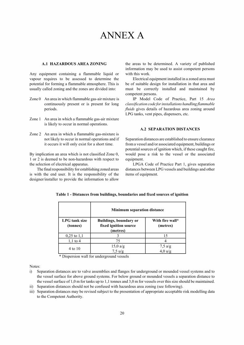
A.1 HAZARDOUS AREA ZONING
Any equipment containing a flammable liquid orvapour requires to be assessed to determine thepotential for forming a flammable atmosphere. This isusually called zoning and the zones are divided into:
Zone 0 An area in which flammable gas-air mixture iscontinuously present or is present for longperiods.
Zone 1 An area in which a flammable gas-air mixtureis likely to occur in normal operations.
Zone 2 An area in which a flammable gas-mixture isnot likely to occur in normal operations and ifit occurs it will only exist for a short time.
By implication an area which is not classified Zone 0,1 or 2 is deemed to be non-hazardous with respect tothe selection of electrical apparatus.
The final responsibility for establishing zoned areasis with the end user. It is the responsibility of thedesigner/installer to provide the information to allow
the areas to be determined. A variety of publishedinformation may be used to assist competent personswith this work.
Electrical equipment installed in a zoned area mustbe of suitable design for installation in that area andmust be correctly installed and maintained bycompetent persons.
IP Model Code of Practice, Part 15 Areaclassification code for installations handling flammablefluids gives details of hazardous area zoning aroundLPG tanks, vent pipes, dispensers, etc.
A.2 SEPARATION DISTANCES
Separation distances are established to ensure clearancefrom a vessel and/or associated equipment, buildings orpotential sources of ignition which, if these caught fire,would pose a risk to the vessel or the associatedequipment.
LPGA Code of Practice Part 1, gives separationdistances between LPG vessels and buildings and otheritems of equipment.
Table 1 - Distances from buildings, boundaries and fixed sources of ignition
Minimum separation distance
LPG tank size(tonnes)
Buildings, boundary orfixed ignition source
(metres)
With fire wall*(metres)
0,25 to 1,1 3 151,1 to 4 75 4
4 to 10 15,0 a/g7,5 u/g
7,5 a/g4,0 u/g
* Dispersion wall for underground vessels
Notes:i) Separation distances are to valve assemblies and flanges for underground or mounded vessel systems and to
the vessel surface for above ground systems. For below ground or mounded vessels a separation distance tothe vessel surface of 1,0 m for tanks up to 1,1 tonnes and 3,0 m for vessels over this size should be maintained.
ii) Separation distances should not be confused with hazardous area zoning (see following).iii) Separation distances may be revised subject to the presentation of appropriate acceptable risk modelling data
to the Competent Authority.

ELECTRICAL INSTALLATION OF FACILITIES FOR THE STORAGE AND DISPENSINGOF LPG AND CNG AUTOMOTIVE FUELS AT VEHICLE REFUELLING STATIONS
21
Table 2 - Minimum separation distances(Distances are as seen in plan view)
Storagevessel
Storage vesselfill connection
LPG pump LPGdispenser
Vehiclebeingfilled
1. LPG storage vessel See CoP 1Part 1
Nil Nilbut not beneath
vessel
0,5 m 3 m
2. Storage vesselfilling connection
Nil Nil 1,0 m 3 m
3. LPG pump Nilbut notbeneathvessel
Nil Nil 1,5 m
4. LPG dispenser 0,5 m 1 m Nil Nil
5. Vehicle being filled 3 m 3 m 1,5 m Nil
6. U/G petrol vesselmanhole with fillconnection
7,5 m 7,5 m 7,5 m 7,5 m Nil
7. U/G petrol vesselmanhole without fillconnection
3 m 3 m 3 m 3 m Nil
8. Above groundvessel for liquids< 65 EC flash point
As CoP Part 1 Table of safety distancesfor flammable liquids
9. Remote petrolvessel fillconnections
7,5 m 7,5 m 7,5 m 7,5 m Nil
10. Petrol vessel vents 7,5 m 7,5 m 7,5 m 7,5 m Nil
11. Petrol dispensers -explosion-protecteddiesel dispensers -explosion-protected
7,5 m
3 m
7,5 m
3 m
7,5 m
Nil
Nil
Nil
Nil
Nil12. Parked cars 6 m or
separationdistance inTable 1 if
less
6 mor separation
distance in Table1 if less
1,5 m Nil Nil
13. Buildings, boundaryor fixed source ofignition
As Table 1 4,0 m 4,0 mfrom
vehicle fillpoint

22
ANNEX B
REFERENCES
British Standards Institution (BSI)1
BS 3871 Part 1 Specification for miniature andmoulded case circuit-breakers. Miniature air-breakcircuit-breakers for a.c. circuits.
BS 7117 Part 1 Metering pumps and dispensers to beinstalled at filling stations and used to dispense liquidfuel - Specification for construction.
European Committee for Standardization (CEN)2
EN 60079-10 Electrical apparatus for explosive gasatmospheres - Classification of hazardous areas.
EN 60742 Isolating transformers and safety isolatingtransformers - Requirements.
EN 60898 Specification for circuit-breakers forovercurrent protection for household and similarinstallations.
IP publications from the Energy Institute3
Guidance on external cathodic protection ofunderground steel storage tanks and steel pipework atpetrol filling stations.
Model Code of Safe Practice in the Petroleum IndustryPart 15 Area classification code for installationshandling flammable fluids.
Liquefied Petroleum Gas Association4
Code of Practice Part 1 Design, installation andoperation of vessels located above ground.
Code of Practice Part 20 Automotive LPG refuellingfacilities.
1 Available from British Standards Institution, 389 Chiswick High Road, Chiswick, London, W4 4AL, UK. Tel: +44 (0)20 89969001, www.bsi-global.com
2 Available from national standards organizations, e.g. BSI
3 Available from Portland Customer Services, Commerce Way, Whitehall Industrial Estate, Colchester, CO2 8HP. Tel: +44(0)1206 796 351, email: [email protected]
4 Available from the LP Gas Association, Pavilion 16, Headlands Business Park, Salisbury Road, Ringwood, Hampshire BH243PB, UK. www.lpga.co.uk