Embed Size (px)
Citation preview

Electrical Installation and Owners Manual
Software 6.6 - (Subject to change without notice)
2091731_B - SR9500LS INSTALLATION MANUAL
USA
www.hormann.us
DC 970 Door Control Panel

Page 2
!
DANGER <> THIS INDICATES DANGER TO THE LIFE AND HEALTHOF THE USER IF APPROPRIATE PRECAUTIONS ARENOT TAKEN
WARNING <> THIS WARNS THAT MATERIALS MAY BE DAMAGED IFAPPROPRIATE PRECAUTIONS ARE NOT TAKEN
NOTE <> IMPORTANT INFORMATION
SYMBOL LEGEND

Page 3
TECHNICAL DATA ........................................................................................................5
SAFETY.........................................................................................................................6
INSTALLATION OVERVIEW ..........................................................................................7
MOUNTING THE CONTROL PANEL ..............................................................................7
INPUT SUPPLY..............................................................................................................7
CONNECTION OVERVIEW ...........................................................................................8
PHASE ROTATION ........................................................................................................8
CONTROL PANEL LAYOUT ...........................................................................................9
WIRING GUIDE .............................................................................................................. 11
CONTROL PROGRAMMING.......................................................................................... 13
RAPID LIMIT ADJUSTMENT .......................................................................................... 14
MENU
Operating mode - Menu 0.1 ...........................................................................................15
Door position - Menu 1.1 to 1.7...................................................................................... 15
Functions - Menu 2.1 to 2.6 ............................................................................................ 16
Safety functions - Menu 3.1, 3.2, 3.4, 3.8 ........................................................................17
Settings only for FI GfA Frequency inverter - Menu 4.1 to 4.9 ..........................................18
Maintenance cycle counter - Menu 8.5, 8.6 .....................................................................19
MEMORY CHECK - Menu 9.1, 9.2, 9.3, 9.4 ....................................................................19
RESET - Menu 9.5 .........................................................................................................20
SAFETY
Door auxiliary switch X2 .............................................................................................. . . 20
Primary monitored safety edge system X2......................................................................21
Type 1: Normally closed edge with a 1K2 ohm resistor .............................................. . .21
Type 2: Normally open edge with a 8K2 ohm resistor ....................................................21
Type 3: Optical safety edge (Vitector) ...........................................................................21
Safety edge function during last 2" of travel - Menu 2.1 .................................................22
Pass door / slack cable switch input (X2 connection) ...................................................23
Page
OPERATING INSTRUCTIONS
CONTROL PANEL ENTRY PLATE LAYOUT ...................................................................10

Page 4
DESCRIPTION OF FUNCTIONS
Stop button (X3 connection) .........................................................................................23
Key switch interrupt automatic closing - Menu 2.4 (X4 connection) ...............................23
Internal and external O/C/S buttons / Key switch (X5 connection) ..................................23
Automatic closing - Menu 2.3 .......................................................................................23
Close after passing - Menu 2.4 ....................................................................................23
Photocell (X6 connection) ............................................................................................ 23
Interruption of the photocell function - Menu 3.2 ............................................................24
Pull switch / Radio control - Menu 2.6 (X7 connection) .................................................25
Mid limit position - Menu 1.6 (X8 connection) ...............................................................25
Relay function - Menu 2.5 (X9 connection) ...................................................................25
Overrun correction - Menu 2.2 ......................................................................................26
Maintenance cycle counter - Menu 8.5 .........................................................................26
Short circuit / overload monitor .................................................................................... 26
DISPLAY CODES / FAULT CODES ..............................................................................27
OPERATING STATUS DISPLAY ....................................................................................30
DECLARATION OF INCORPORATION ..........................................................................31
FUNCTION OVERVIEW.................................................................................................32
Page
OPERATING INSTRUCTIONS

Page 5
TECHNICAL DATA
Dimensions 20" x 20" x 8" (W x H x D)
Mounting Vertical
Power supply Configurations available: 208V 3 Phase +/-5%, 60Hz* 230V 3 Phase +/-5%, 60Hz 460V 3 Phase +/-5%, 60Hz 575V 3 Phase +/-5%, 60Hz**Transformer required
DC 970 Controller supply 24Vac 15VA
External supply 1 24Vac (X1.8, X1.9), Fuse FI (1A )
External supply 2 24Vdc (24V, GND), 150mA Max.Short circuit protected
Inputs 24Vdc / typ. 10mASignal must be more than 100ms
Relay output 24Vac 1A, Inductive loads require a protected surgesuppressors
Temperature Operating: 32.... 104FStorage: 32....122F
DC 970 Door control panel
Humidity: 93% Max. (non condensing)
Vibration: Vibration free, mounted on a solid surface
Protection class Nema 4
Approval C UL US

Page 6
SAFETY
All electrical work must be performed by qualified personnel in accordance to NEC, local, state,and federal codes.
This control panel has been built in accordance with CUL 508a, EN 12453 Industrial,commercial and garage doors and gates - Safety use of power operated doors –Requirements, and EN 12978 Industrial, commercial and garage doors and gates - Safetydevices for power operated doors - Requirements and Test methods. To maintain andensure safe operation, the user must observe and follow the directions and warnings containedin this manual.
Important note!Do not install, operate, or service this DC 970 control panel unless you haveread and fully understand the safety practices, warning, and installationinstructions contained in this manual.
A separate fused disconnect (usually supplied by others) is required as a meansof disconnecting incoming power from the control panel.The fused disconnect must be installed next to the control panel.The disconnect must be off, locked and tagged before wiring can begin.The DC 970 control panel contains HIGH VOLTAGE.
High voltage power leads to the operator must be run in a separate conduitfrom the low voltage control wires.Installing conduit through the top or sides will void the control panel warranty.Any modifications to the DC 970 control panel without the manufacturersapproval will void the warranty.Verify all field wiring to ensure terminal connections are tight and correct prior tostart-up.
All wiring identified in this manual is for information only. For final electrical connections reviewthe electrical wiring diagram shipped in the control panel.Do not use if any component appears to be damaged, replace immediately.To aid the wiring and service of all electrical circuits, label all wire ends.Specified technical data limits are not to be exceeded under any circumstance.
Failure to follow these safety practices may result in personnel bodily injury, ordeath.

Page 7
INSTALLATION OVERVIEWOnce the door is installed according to the mechanical installation guide, follow these steps tocorrectly install and start-up the DC 970 control system.
• Installation Mount the control panel page 7
• Check Input supply page 7
• Installation Connection overview page 8
• Check Phase rotation page 8
• Programming Rapid limit adjustment page 13
Door can now operate in constant pressure mode.
• Installation Safety page 10, 15, 16
• Programming Door functions page 14
Door is now functional.
MOUNTING THE CONTROL PANELTo mount the enclosure, confirm that the surface is flush, solid, and vibration free. The controlpanel should be mounted 48" above the finished floor for ease of troubleshooting. A separatefused disconnect (supplied by others) must be installed next to the control panel. Area temperaturemust between 32 to 105 F.
Important note!All electrical work must be performed by qualified personnel in accordance toNEC, local, state and federal.
INPUT SUPPLYConnect the supply to terminal L1, L2, L3 and GND. Prior to turning on the supply verify that itmatches the control panel and operator nameplate, otherwise damage to the equipment mayoccur. Review electrical wiring diagram shipped in the control panel for connections.
Important note!The DC 970 control panel contains high voltage.

Page 8
CONNECTION OVERVIEW
Important note!All electrical works must be performed by qualified personnel in accordance toNEC, local, state and federal codes.High voltage power leads to the operator must be run in separate conduit fromthe low voltage wires.Installing conduits through the top or sides will void the control panel warranty.All wiring identified in this manual is for information only. For final electricalconnections review the electrical wiring diagram shipped in the control panel.
PHASE ROTATION
Important note!The DC 970 control panel contains high voltage. The disconnect must be off,locked and tagged before any wiring can be changed.
After the input supply voltage and digital limit has been verified and connected, confirm that the phase rotation of the electrical motor is correct. When pressing the open foil button momentarily the door shall move up. When pressing the down foil button momentarily the door shall move down. If this does not occur change the phase rotation.For all standard three phase operators: Swap U, and W.
Basic connections are required for start-up in constant pressure mode. Connect the operator toU,V,W and GND ground terminal blocks. Then connect the digital limit (low voltage) to terminal1 through 6.

Page 9
BASIC CONNECTIONS
ACTIVATION
SAFETY
CONTROL PANEL LAYOUT
O/C/S Push Buttons
(Minimum requirementfor door operation.
Door will now operate inconstant pressure mode)
Door specific electrical wiring diagram is shipped in the control panel.!
Supply voltage 4C/14AWG min Motor connection 4C/14AWG min Brake 2C/14AWG min
Digital limit 6C
Pull switch 2CRadio controls 4C3 Button station 5C
Photocell 5CSafety edge Type 1 2CSafety edge Type 2 2CSafety edge Type 3 3CPass door/Slack cable or Crash switch 2C

CONTROL PANEL ENTRY PLATE LAYOUT
Page 10
! Warranty may be voided if hole pattern is not followed!

Page 11
WIRING GUIDE
L1L2L3
GND
230/
460/
575
3ph
60Hz
SUPP
LY
X1
UVW
GND
X1
3ph
60Hz
Mot
or-
Conn
ectio
n
123
DIGI
TAL
LIM
IT
DES
456
2.1
2.2
2.3
2.4
2.5
2.1
2.2
2.3
2.5
X2pl
ug
Rece
iver
Tran
smitt
er
470Ω
1/4
W*
Resis
tor
Stan
dard
SR
9500
Con
nect
ions
Mon
itore
d U
L325
Th
ru-B
eam
Jum
per
Wire
less
Rev
ersi
ng
Edge
24V
24V
+24V
6.16.2
Tran
smitt
er -
Rece
iver
Light
Cur
tain
X6
GND
34
52
12
1
1 - B
row
n2
- Blu
e4
- Bla
ck
24V1.8
6.16.2
X6
1.9
34
52
1
Tran
sRe
cv
Oth
er O
ptio
ns
OEM
Pro
vide
d O
ptio
nal S
afet
ies
Opt
ical
two
wir
e ed
ge s
yste
m (
1)(S
tand
ard
UL3
25 F
raba
Thr
u-Be
am)
*Not
e: R
esist
or m
ust b
epl
aced
in c
ircui
t prio
r to
appl
ying
pow
er to
thru
-bea
mto
avo
id d
amag
e to
the
rece
iver
.
1 - R
ed1
- Whi
te2
- Bla
ck4
- Yel
low
2.1
2.2
2.3
2.4
2.5
2.1
2.2
2.3
2.5
X2pl
ug
470Ω
1/4
W*
Resis
tor
Jum
per
Opt
ical
two
wir
e ed
ge s
yste
m (2)
(Sta
ndar
d U
L325
Fra
ba T
hru-
Beam
)*N
ote:
Res
istor
mus
t be
plac
ed in
circ
uit p
rior t
oap
plyi
ng p
ower
to th
ru-b
eam
to a
void
dam
age
to th
e sig
nal
mer
ging
uni
t.
Tran
smitt
er1
Rece
iver1
1.8
X61.9
Tran
smitt
er2
Rece
iver2
3
4
1
2
1 - B
rown
2 - W
hite
3 - Y
ellow
4 - G
reen
*Not
e: 8
.2K
Ohm
Res
istor
mus
t be
plac
ed a
cros
s X2
term
inal
s 2.
3 an
d 2.
4w
hen
usin
g OE
M L
ight
Cur
tain
*Not
e: 8
.2K
Ohm
Res
istor
mus
t be
plac
ed a
cros
s X2
term
inal
s 2.
3 an
d 2.
4w
hen
usin
g OE
M L
ight
Cur
tain

Page 12
WIRING GUIDE
24V
24V
+24V
6.16.2
24V+24V
6.16.2
Refle
ctive
phot
ocel
lTr
ansm
itter
- Re
ceive
rph
otoc
ell
24V
24V
+24V
6.16.2
Tran
smitt
er -
Rece
iver
phot
ocel
l - P
NP
X6X6
X6or
or6.16.2
Pull
switc
h
X7or
X7
3.13.2
4.14.2
Stop
butto
nIn
terru
ptau
tom
atic
closin
gtim
er
5.15.25.35.4
Keye
d O/
C sw
itch
Keye
d O/
C sw
itch
with
sto
p bu
tton
5.15.25.35.4
5.15.25.35.4
Open
Auto
clo
se
5.15.25.35.4
Thre
e bu
tton
stat
ion
(O/C
/S)
X3X4
X5X5
X5X5
oror
or
21
Mid
pos
ition
key
/Se
lect
or s
witc
h
21
8.18.2
X8
1.81.9
X1
9.19.29.3
X9
9.19.29.3
X9
Dry
N.O.
Cont
act
24Va
c co
llre
lay
+24V
7.17.2
24Va
c/24
Vdc
1.81.9
X6X1
Radi
o re
ceive
r
5.2
5.3
X5
24Va
c
1.81.9
X1
Floo
r loo
p
Floo
r loo
pde
tect
or
for o
peni
ng a
ndho
ld o
pen
5.2
5.3
X5 24Va
c
1.81.9
X1
Mot
ion
dete
ctor
GND
GND
GND
oror
GND
5.1
5.1
34
52
12
13
45
21
32
12
1
3 4
11 12
12
P
Open
Clos
e
12
P
Open
Clos
e
11 12St
op
13 14Op
en11 12
Stop
13 14Op
en
13 14Cl
ose
1 2
1 2
13 14
1114
L3L4
A1A2
1114
A1A2
Oth
er O
ptio
nal C
onne
ctio
ns

Page 13
CONTROL PROGRAMMING
5. Exit programming
Turn selector until display = 00 Press selector
and
1. Enter programming Mode
Press selector switch for 3 sec. until display = 00
2. Chose program and confirm
Turn selector Press selector
3. Adjustment
Turn selector Press foil buttons
4. Save
Press selector Press stop-button
and
Setting Door position
or
Function Door position
or
further adjustments

Page 14
RAPID LIMIT ADJUSTMENT
Rapid limit adjustment is completeThe door open and close buttons will operate in constant pressure mode.
To change operating mode see Menu 0.1 “Door function“(to change operating mode a safety monitored device must be connected)
To re-adjust open limit see Menu 1.1 or 1.3, for close limit see Menu 1.2 or 1.4.To reset and start over see Menu 9.5 page 19
1. Setting the open limit (use control panel foil buttons for adjustment)
press button to reach the upper limit
Door open
Displayblinking
2. Save the open limit
Press stop-button for 3 sec. untilthe display changes Display
changes
3.Setting the close limit (use control panel foil buttons for adjustment)
press button to reach lower the limit
Displayblinking
Door close
4. Save the close limit
Press stop-button for 3 sec. untilthe display changes Display
changes
Once the phase rotation has been verified the limits can be adjued. Fine adjustments can bemade with Menu 1.3 or 1.4 (Page 14). Safety limits and FI GfA Frequency inverter slow downlimits are automatically adjusted.
The OPEN limit can only be saved after the door travels for at least one second in theopen direction.
1a. Reversing for FI GfA Frequency inverter only (for all others see page 8)
To reverse the motor rotationkeep both buttons pressed forthree seconds until the displaychanges Display
blinkingDisplaychanges

Page 15
Operating mode - Menu 0.1
Door position - Menu 1.1 to 1.7
MENU
4. Save3. Adjustment2. Choose program andconfirm
Pressselector
Constant pressure OPENConstant pressure CLOSE
Door function
Impulse OPENConstant pressure CLOSE
Impulse OPENImpulse CLOSE
Not available(Do not set to 4)
Press stopButton
Move doorup or down
Open limitcoarse adjustment
Pressselector
Move to mid positionMid limit setting
Move to output relay positionOutput relay position setting(See Menu 2.5)
Press stopButton
Press stopButton
Pre-limit safety edge canchange using +/-
Pre-limit safety edgefine adjustment(See Menu 2.1)
Pressselector
Pressselector
Press stopButton
Move doorup or down
Close limitcoarse adjustment
Open limit can changewithout door movement using +/-
Open limitfine adjustment
Close limit can changewithout door movement using +/-
Close limitfine adjustment

Page 16
MENU
Functions - Menu 2.1 to 2.6
4. Save3.Adjustment2. Choose program andconfirm
Pressselector
Safety edge stops ifactivated <active>
Safety edge functionduring last 2" of travel(See Menu 1.5) Safety continues to the bottom limit
if activated <ignored>If safety edge is activated, bottomlimit is automaticaly adjusted
Pressselector
OFFOverrun correction
ON
Pressselector
Adjustable between 1 - 240 sec.0 = OFF
Automatic closing
Pressselector
OFFPhotocell close afterpassing
Immediately closes after 3sec delay
Pressselector
OFFRelay function
Output contact impulse(See Menu 1.7 for positionadjustment, and page 11 for wiring)
Continuous output contact(See Menu 1.7 for positionadjustment and page 11 for wiring)Output for lights, flashing 3 sec.prior to opening, closing, andcontinuous contact during travel(See page 11 for wiring)Output for lights, flashing 3 sec.prior to closing, and continuouscontact during travel(See page 11 for wiring)
Vehicle recognition, closes whenactivated for more than 1,5 sec.
Output for lights, on 3 sec. prior toopening, closing, and continuouscontact during travel(See page 11 for wiring)Output for lights, on 3 sec. prior toclosing, and continuous contactduring travel(See page 11 for wiring)
Not available(Do not set to 4)

Page 17
OFFPhotocell interrupt function
ON (See page 22 for details)
Functions - Menu 2.1 to 2.6
Pressselector
OFFNot Available(Do not adjust)
Pressselector
Not available(Do not set to 1)Not available(Do not set to 2)
MENU
4. Save3. Adjustment2. Chose program andconfirm
Slack cable / Pass doorDoor auxiliary switchfunction
Pressselector
NormalSafety edge reverse delay
Reduce delay
Increase delayThree adjustment levels are available
Pressselector
Pressselector
Impulse to Open or Close, impulseduring closing door stops and re-opens
Special activation function(X7): Pull switch / Singlebutton radio remotecontrol only
Commands O/C/SOpenStopCloseStop Open
Safety functions - Menu 3.1, 3.2, 3.4, 3.8
Crash detector (NC Contact)
Crash detector (NO Contact)(See page 19 for details)
Page 18
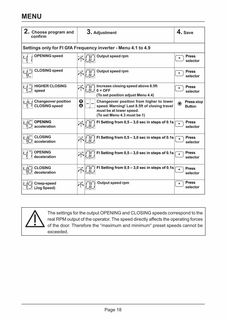
MENU
Output speed rpmOPENING speed
Output speed rpm
Increase closing speed above 8.5ft0 = OFF(To set position adjust Menu 4.4)Changeover position from higher to lowerspeed. Warning! Last 8.5ft of closing travelmust be at lower speed.(To set Menu 4.3 must be 1)
Changeover positionCLOSING speed
OPENINGdeceleration
CLOSINGdeceleration
CLOSINGacceleration
OPENINGacceleration
CLOSING speed
HIGHER CLOSINGspeed
Settings only for FI GfA Frequency inverter - Menu 4.1 to 4.9
4. Save3. Adjustment2. Choose program andconfirm
Pressselector
Pressselector
Pressselector
Pressselector
Pressselector
Pressselector
Pressselector
Press stopButton
The settings for the output OPENING and CLOSING speeds correspond to thereal RPM output of the operator. The speed directly affects the operating forcesof the door. Therefore the “maximum and minimum“ preset speeds cannot beexceeded.
FI Setting from 0,5 – 3,0 sec in steps of 0.1s
Creep-speed(Jog Speed)
Pressselector
Output speed rpm
FI Setting from 0,5 – 3,0 sec in steps of 0.1s
FI Setting from 0,5 – 3,0 sec in steps of 0.1s
FI Setting from 0,5 – 3,0 sec in steps of 0.1s

Page 19
MEMORY CHECK - Menu 9.1, 9.2, 9.3, 9.4
Pressselector
Info: 7- digit cycle counter
Last 2 faults would be alternately displayed.
Program version will be displayed
Displayed
Info: Last 2 faults Pressselector
Info: Program changes7- digit
Info: Program version
M HT ZT T H Z E
Pressselector
Pressselector
M HT ZT T H Z E
The cycles would be displayed one at a time asfollow.M = 1.000.000 H = 100HT = 100.000 Z = 10ZT = 10.000 E = 1T = 1.000
The Number of program changes would bedisplayed one at a time as follow.M = 1.000.000 H = 100HT = 100.000 Z = 10ZT = 10.000 E = 1T = 1.000
2. Chose program andconfirm
MENU
01-99 correspond from 1.000 up to99.000. “CS“ counts down for service.
Counter Service (CS)maintenance
“CS“ is displayed, clear by setting anew interval in Menu 8.5
“CS“ is displayed and function changes toconstant pressure mode. Clear by setting anew interval in Menu 8.5Same as above, but “CS“ can also bereset for 500 more cycles by the enduser.Press the stop button for 3 sec. to activate.
Maintenancedue CS=0
Maintenance cycle counter - Menu 8.5, 8.6
4. Save3. Adjustment2. Chose program andconfirm
Pressselector
Pressselector

Page 20
RESET - Menu 9.5
RESETS all exceptcycle counter(Menu 9.1) andProgram changecounter (Menu 9.3)
Reset Press stopbutton3 sec.
4. Save3. Adjustment2. Chose program andconfirm
SAFETY
Door auxiliary switch X2This is a door mounted switch that is connected via the spiral cable to the control panel. This switchcan be used and programmed as one of two functions.
Menu 3.4 Door auxiliary switch.
Function Reaction following the activationSlack cable / Contact open: Door stopsPass door Contact closed: Door ready to run.Crash detector Contact momentarily
opened: Door will stop immediately.Contact closed: The door will then only function in constant pressure
mode. The door is reset when the control panelmounted “stop“ foil button is pressed for aminimum of three seconds. (If using a GfAfrequency inverter the door will move in creepspeed).
If a passdoor, slack cable, or crash switch contact is used, remove jumper and connect to terminal X2.1, X2.2. See page 21 for wiring.

Page 21
Primary monitored safety edge system X2The controller recognizes 3 different safety edges systems. By using a four conductor spiral cable will allow any combination of safety edge systems and door auxiliary switch functions.
Type 1: Normally closed edge with a 1.2K ohm resistorThis system is made for pressure switches with a normally closed contact in series with an end-of-line 1.2K +/- 5% 0,25W resistor. By compressing the rubber profile, a pressure is transmitted through the plastic hose to the air-wave pressure switch which momentarily opens the 1.2K ohm circuit to signal an activation. In a normal state a constant 1.2K ohm circuit is maintained.When a door is closing, a pressure must be sensed by contact with the finished floor within two seconds of the last 2" of travel to confirm the safety edge test. If the pressure switch does not become activated during this time, the door safety edge test failed and shows a 2.8 fault. Door will only close in constant pressure mode.
Type 2: Normally open edge with a 8.2K ohm resistorThis system is made for electrical safety edges with an end-of-line 8.2K +/- 5% 0,25W resistor. The resistor must be connected parallel with the safety edge end. By compressing the rubber profile, a momentary short circuit is created across the 8.2K ohm resistor to activate the safety edge. In a normal state a constant 8.2K ohm circuit is maintained. This is a continually monitored system.
SAFETY
1.2kΩ 1/4W Resistor
2.12.22.32.42.5
1234
Spiral Cable
ST+STSK1SK2
1234
DW
Terminal Box (Jumper only if not used)X2Terminal Plug
2.12.22.32.42.5
1234
Spiral Cable
ST+STSK1SK2
1234
Terminal Box (Jumper only if not used)X2Terminal Plug
8.2kΩ 1/4W Resistor
Type 3: Optical safety edge (Vitector)This system incorporates an infrared sensor for optically sensing edges. By compressing the rubber profile, the blocked beam will activate the edge. This is a continually monitored system.
2.12.22.32.42.5
123
4 Spiral Cable
ST+ST
SK/gSK/w
12
34
Terminal Box
Pass Door Slack Cable, Crash Switch
(Jumper only if not used)
SK/b BrownGreenWhite
ReceiverTransmitter
X2Terminal Plug
Pass Door Slack Cable, Crash Switch
Pass Door Slack Cable, Crash Switch

Page 22
Safety edge function during last 2" of travel - Menu 2.1Function Reaction following an activationActive safety edge Will stop between the floor and 2" and will not reverse
De-activated safety edge No reaction, door continues to the bottom limit
Active safety edge+ Stops and automatically re-adjusts the bottom limit with thedownward automatic next movementfloor adjustment
The function ‚Auto ground adjustment‘ is used for doors with a lifting cable such as a sectionaldoor or vertical lift-gate. Automatic correction of a slack cable or a change of ground height up to1-2" is possible. The slack cable switch will still be monitored.
Important note!The automatic ground adjustment Menu 2.1 setting 3 only operates with:Type 2: Normally open edge with a 8.2K ohm resistor or Type 3: Optical safetyedge (Vitector) and must be adjusted to contact the finish floor each cycle.
Important note!When the safety edge has been activated twice the automatic closing featurewill be interrupted and fault F2.2 will be displayed.To reset the fault press the control panel foil button so that the door travelsdown to the closed position.
SAFETY
Important note!When using a safety edge system, verify that when the safety edge is activatedthe door stops and reverses to the open position.
Important note!Consider EN 12978 for Industrial, commercial and garage doors and gates -Safety devices for power operated doors - Requirements and Test methods.
2.1
2.2
2.3
2.4
2.5
2.3
X2Terminal
2.4
Plug
8.2kΩ 1/4W Resistor
Important note!If using alternative, self-monitored Safety Edge Device - an 8.2K ohm 0,25W resistor must be connected across terminals 2.3 and 2.4 of the X2 Terminal.

Page 23
Stop button (X3 connection)Stop button can stop door movenment at any time.
SAFETY
Pass door / slack cable switch input (X2 connection)The pedestrian pass door or cable slack switch is connected to terminal X2.1, X2.2 and iscontinously monitored by the control panel. If the pedestrian pass door or slack cable circuitbecomes open the door stops and will not operate.
Important note!This is a momentary stop button. Activators can re-acivate door travel. This isnot a latched emergency stop circuit.
Internal and external O/C/S buttons / Key switch (X5 connection)Control panel foil and external push buttons operate seperately from each other. The controlpanel foil buttons always have priority when pressed at same time.
Automatic closing - Menu 2.3The close time delay is adjustable between 1 - 240 sec.
Important note!In the open position the timer can be reset by pressing the stop button, or initiatinganother open command.
Close after passing - Menu 2.4This feature will keep the door open until the photocell is interrupted and re-established. Thedoor closes after a fixed 3 second pre-warning.
The automatic closing time can be interrupted with a maintained normally closed contact.Key switch interrupt automatic closing - Menu 2.4 (X4 connection)
Important note!The 24Vdc power supply load may not exceed 150mA.
Photocell (X6 connection)An external non failsafe photocell can be connected to the controller. A 24Vdc supply for thephotocell is available.
DESCRIPTION OF FUNCTION

Page 24
Interruption of the photocell function - Menu 3.2This function is to ignore the photocell below a specific position. An example for such arequirement would be a spiral cable breaking the photocell near the closed position. To learnthe switching position the door requires 2 full OPEN and CLOSE cycles. During the close cyclethe photocell shall be broken two times consecutively at the same position. The position is thenmemorized, and the photocell is ignored below this setting. To activate set Menu 3.2 adjustmentto 1.
After the program was selected a 2 appearson the left display (see fig.)
With the first interruption of the photocell the displaychanges to 1
and after the second interruption it changesto CLOSE (see fig.); the function is activated.
If the adjustment was not successful a 2 will be displayed for short period. If so the lastswitching position will be the new first position and a 1 is displayed. The door must travel a newcycle so that the second position will be memorized. After programming, setting must be tested.
Door Position Interrupted photocell beamDoor closed No reaction, remains openDoor opening No reaction, remains closedOpen limit *) No reaction, remains openwithout timer activeOpen limit *) Resets the open timer for automatic closingwith active timerOpen limit *) Close timer stops, once the photocell is interrupted and re-with active timer established.and close after passing Door closes after 3 sec.Door closing Stops and opens to the open position *)
The Photocell is to be connected in a normally closed operating mode. If the photocell isinterrupted, or if it malfunctions, the electrical contact will become open and cause the following:
*) or to the mid position when the key or selector switch contact (X8.1, X8.2) is closed.
Important note!While programming this function, the photocell will not reverse to open.
.
DESCRIPTION OF FUNCTION

Page 25
DESCRIPTION OF FUNCTION
Door position Door operationClosed Opens to fully open or mid limit positionOpening Continues to open (no change)
Open Door closes to fully closed positionMid limit position (if set) Door closes to fully closed positionMoving downwards Door STOPS and moves BACK UP to the open Position*)See functions Menu 2.6 Adjustment 0.2 O/C/S function
Pull switch / Radio control - Menu 2.6 (X7 connection)It is possible to connect a pull switch or a radio receiver’s dry contact to input X7.1 and X7.2 andactivate the single open/close function.The following is the sequence of operation for the single input activator:
To activate the output relay function at a specific height, Menu 1.7 must be set.
*) or to the mid limit position when the key or selector switch contact (X8.1, X8.2) is closed.
Mid limit position - Menu 1.6 (X8 connection)Mid limit can be activated or de-activated by connecting a key or selector switch to X8.1 and X8.2. With an open contact across X8 the door will travel to the open limit. With a closed contact the door will travel to the mid limit position. Menu 1.6 is used to set the mid limit position.
Relay function - Menu 2.5 (X9 connection)The output relay function can be configured as 1 of the 6 settings found in Menu 2.5.See page 12 for wiring.
Important note!Only one programable relay is available, for a single function.

Page 26
Important note!This can only operate with a continuously self monitored safety edge type 2or type 3 system, and must contact the finished floor every cycle. See X2description on page 20-21.
Overrun correction - Menu 2.2The stopping position of the door can be affected by various factors such as temperature andcable stretch. To have the same stopping position the overrun correction can be activated withMenu 2.2. Adjustment 0.0=OFF, 0.1=ON.
DESCRIPTION OF FUNCTION
Short circuit / overload monitorThe DC 970 control panel includes 2 supplies for external devices.
24Vac, 1A max.24Vdc, 150mA max.
A 24Vdc short circuit turns the display off.
Maintenance cycle counter - Menu 8.5Adjustable maintenance cycle counter makes it possible to pre-adjust a max. number of cyclesuntil maintenance is due.The maintenance cycles can be adjusted from 1.000 up to 99.000; in steps of 1.000 cycles.Three different door functions in Menu 8.6 are available once the maintenance cyle count hasbeen reached.A cycle is considered when the door reaches the top limit.Upon maintenance, the cycle counter then could be re-adjusted to a new maintenance periodwith a new door function.
Important note!Great variations of temperature during a time when the door is not in use,could cause a position variation of about 0.375". This will re-adjustautomatically after a closing cycle.

Page 27
DISPLAY CODES / FAULT CODESThe DC 970 can display up to three different status conditions one after another. Each status isdisplayed with a letter and a number. The letter and the number are flashing alternately.FAULT = F and a command = E.
Report Description Solution
Chain hoist engaged ormotor-winding thermalswitch active
Check chain hoist green lever or whether the drive unitthermal switch is active.
Door auxilary switch,pass door or slack cablecontact is open
Circuit should be closed. Check for proper operationof the pedestrian pass door or slack cable contact.Verify whether the electrical cable is open.
Stop button activated Stop circuit should be closed. Check if the stop buttonis activated. Verify whether the electrical cable is open.
Safety edge not recognized Check that the safety edge is connected correctly andverify that the correct type has been selected in theprogram.
Photocell activated Check photocell alignment and it‘s proper installation.Verify whether the electrical cable is open.
Safety edge 8.2K activated
Safety edge 8.2K defective
Safety edge 1.2K activated Check the safety edge is activated and verify whether ashort exists in the electrical cable.
Safety edge 1.2K defective Check the safety edge resistance and verify whether theelectrical cable is open.
Safety edge 1.2K pneumaticsystem TEST failure
Check that the correct safety edge type has been selectedin the program and that testing in the lower door positionis correct.
Optical safety edge activatedor defective
Check that the correct safety edge type has been selectedin the program and verify whether the electrical cable isopen.
Safety edge activated for 20consecutive cycles
Check if there is an obstacle in the opening. Verify whe-ther the electrical cable is open or if a short exists.
Check the safety edge and verify whether a short exists inthe electrical cable.
Check the safety edge resistance and verify that thecorrect safety edge type has been selected in the program.
Door auxilary switch, circuitfailure, voltage is less than24Vdc
Verify that the voltage between 24V and GND is 24V dc.Check for proper connections of the pedestrian pass dooror slack cable switch. To reset the fault, open and closethe pass door switch or switch OFF and ON the main dis-connect.
Failure input pass door(X 2.1 - X 2.2)
To reset the fault, open and close the pass door switch orswitch main disconnect OFF and ON. If necessary replacethe control panel.

Page 28
DISPLAY CODES / FAULT CODES
Report Description Solution
Open safety limit activated Turn OFF the disconnect and move the door down withthe hoist or crank until the cam is off the safety limit.Open limit may need to be re- adjusted.
Close safety limit activated Turn OFF the disconnect and move the door up withthe hoist or crank until the cam is off the safety limit.Close limit may need to be re- adjusted.
Door load monitor hasactivated
Check the door mechanism for tightness.
ROM(Read only memory)– Fault
Internal fault report
RAM(Random access memory)– Fault
Internal control fault
DES(Digital limit)– no response
Check electronic limit DES connection. To reset the fault,open and close the pass door switch or switch maindisconnect OFF and ON. If necessary replace thecontrol panel or digital limit (DES).
Drive unit does not operate Check the door mechanics. Verify input power andfuses. Check that the limit shaft does rotate. Verify phaserotation.
Phase rotation failure Check supply phase.
Limits not adjusted Adjust limits
To reset the fault, open and close the pass door switchor switch main disconnect OFF and ON.
To reset the fault, open and close the pass door switchor switch main disconnect OFF and ON.
To reset the fault, open and close the pass door switchor switch main disconnect OFF and ON.
To reset the fault, open and close the pass door switchor switch main disconnect OFF and ON.
The drive does not respond tothe given command e.g. torqueoverload or a frequencyinverter failure.
Improper movement when dooris stopped, e.g. worn brake orincorrect inverter signal.
The fault will reset with the next door command. Checkfunction of the brake and replace if necessary.Otherwise if the fault re-appears replace the frequencyinverter.The fault will reset with the next door command. Checkdrive load and supply voltage. If this is correct and ifthe fault re-appears replace the frequencyinverter.
Door auxilairy switch: functionCrash detector acivated.
Check if the switch is properly installed or is activated.After repair: Press Stop button for a minimum of 3 secto reset.

Page 29
DISPLAY CODES / FAULT CODES
Over speed closing To reset the fault, switch main disconnect OFF and ON.If the fault re-appears replace the frequency inverter.
Report Description Solution
Internal frequency inverter com-munication fault.
Insufficient supply or afrequency inverter fault.
The fault will reset with the next door command. Verifysupply voltage, fusing, acceleration and decelerationsettings.
Circuit overload The fault will reset with the next door command.Increase acceleration and or deceleration settings.
Exceeding the frequencyinverter temperature e.g. load,high cycles.
The fault will reset with the next door command.Reduce load, and/or cycles.
Exceeding motor current orfailure of the frequency inverter.
Check the door mechanism, weight and friction.The fault will reset with the next door command. If thefault re-appears replace the frequency inverter.
Frequency inverter group status The fault will reset with the next door command. If thefault re-appears replace the frequency inverter.
To reset the fault, switch main disconnect OFF and ON.If the fault re-appears replace the frequency inverter.
Check the brake, replace if required. If the fault re-ap-pears replace the frequency inverter.
Brake fault (Frequency inverter)

Page 30
Open command
Stop command
Close command
Report Command description
Display off = short circuit or overload with the 24Vdc supply.Check connection between terminal 24V and GND terminal on the DC 970.
OPERATING STATUS DISPLAY
Maintenance due (Counter service)
Closing
Door between set limits
Report Status
Door at upper limit
Door at lower limit
Opening
flashing
flashing

Page 31
Standards appliedDIN EN 12453 Doors - safety in use of power operated doors
DIN EN 12978 Industrial, commercial and garage doors and gates -Safety devices for power operated doors - Requirements and Test methods
DIN EN 60335-1 Safety of household and similar electrical appliancesPurposes - Part 1 : General requirements
DIN EN 61000-6-2 Electromagnetic compatibility (EMC) Part 6-2Generic standard – Emission standard for industrial environments
DIN EN 61000-6-3 Electromagnetic compatibility (EMC) Part 6-3Generic standard – Emission standard for residential,commercial and light-industrial environments
We, theGfA - Gesellschaft für Antriebstechnik
hereby declare that the following products are conform with theabove EC Guidelines and are only intended for installation in door equipment.
We undertake to transmit in response to a reasoned request by the appropriate regulatoryauthorities the special documentson the partly completed machinery.
Authorised representative for the compilation of the relevant technical documents(internal EU address)
Dipl.-Ing. Bernd SynowskyDocumentation representative
Incomplete machines within the meaning of the EC Directive 2006/42/EC shall only be intendedto be integrated into other machines (or into other incomplete machines/systems) or to be
assembled with them to form a complete machine within the sense of the Directive. Therefore,this product cannot be commissioned before it is determined that the entire machine/system to
which it was integrated shall comply with the provisions of the Machinery Directive indicatedabove.
Door control panel DC 970
DECLARATION OF INCORPORATIONin the terms of Machinery Directive 2006/42/ECfor partly completed machinery, Appendix II Part B
Declaration of conformancein terms of EMC Directive 2004/108/EC
GfA-Gesellschaft für AntriebstechnikDr.-Ing. Hammann GmbH & Co. KG
Wiesenstraße 8140549 Düsseldorf
Telefon: +49 (0) 211-500 90 0Telefax: +49 (0) 211-500 90 90
www.gfa-elektromaten.de
Düsseldorf, 01. 01. 2010 Stephan Kleine CEO Signature
Erstelldatum: 01.01.2010 Zeichnungs-Nr.: 52397057 Revisionsstand: b

Page 32
FUNCTION OVERVIEW
• DC 970 Control panel with DES digital limit
• 7- Segment led display showing- Program settings- Display Command<>Info<>Fault
• Mains supply- Configurations available:
208V 3 Phase +/-5%, 60Hz*230V 3 Phase +/-5%, 60Hz460V 3 Phase +/-5%, 60Hz575V 3 Phase +/-5%, 60Hz**Transformer Required
• Door operating modes- Constant pressure open and close (without a monitored safety edge connected)- Impulse open and constant pressure close (wthout a monitored safety edge connected)- Impulse open and close (with a monitored safety edge connected)- Automatic open and delay close (with a monitored safety edge connected)
• Integrated safety edge systems- 8.2K normally open contact- 1.2K normally close contact- Optical safety edge system (System Vitector)
• Automatic close feature- Programmable from 1 to ...240 Sec. max.- 3 sec close after passing function- Can be interrupted by a separate switch
• Supply for external devices- 24Vac, 1A Max.- 24Vdc, 150mA Max.
• Electronic DES limit (digital limit)
• Plug for spiral cable (monitored safety edge and auxiliary door contact)
• Control panel mounted OPEN / CLOSE / STOP buttons
• Additional terminals for:- Stop buttons- External three button station (O/C/S)- Reversing photocell with adjustable delay closing- One channel - impulse functions e. g. Pull switch or radio control for O/C/S function- 1 potential free programmable relay output either NC or NO- Key/Selector switch for mid limit position

German Engineered, American Made
Our promise to you.As one of the world’s leading manufacturers of doors, we’re committed to providing the best quality, value, and selection. Whether industrial or commercial, retail automotive, parking garages, transit,
For assistance, call 1.800.365.3667
waste management, fire stations or food processing, we have the door you’re looking for. The Hörmann product line has a door for any application, from one manufacturer.
Hörmann High Performance Doors, Burgettstown, PAHigh Performance Doors
CONNECT WITH US Environmental commitment has been part of our corporate culture for decades. From our manufacturing processes to the products we make.
In everything we do we strive to minimize energy and use of resources through efficient processes, long-lasting quality and innovative engineering.
Everything you’ve always wanted in a high performance door, and more
TNR Doors, Barrie, Ontario, CanadaHigh Performance Doors
Starpointe Business Park • 117 Starpointe Boulevard • Burgettstown, PA 15021-9506Phone: 724.385.9150 • Fax: 724.385.9151 • www.hormann.us • Email: [email protected]