Embed Size (px)
Citation preview
ELECTRICAL FUNDAMENTALS
FOR
MECHANICAL SERVICES
vital experience in acoustics | civil | electrical | ESD | fire | hydraulic | lifts
mechanical | property asset management | structural | underground power
Albany, Brisbane, Busselton, Darwin, Gold Coast,
Melbourne, Perth, Shenzhen, Sydney
E: [email protected] W: www.wge.com.au
Prepared by: Angus GrantDate: May 2013
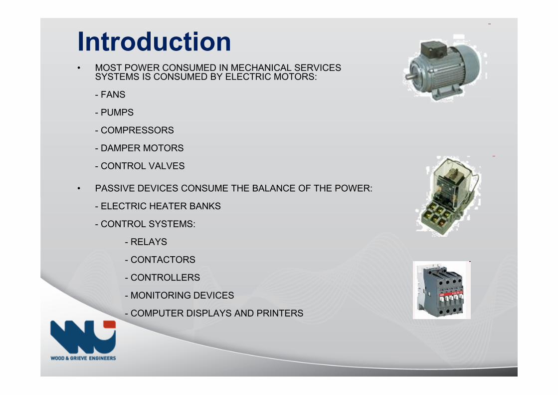
• MOST POWER CONSUMED IN MECHANICAL SERVICES SYSTEMS IS CONSUMED BY ELECTRIC MOTORS:
- FANS
- PUMPS
- COMPRESSORS
- DAMPER MOTORS
- CONTROL VALVES
• PASSIVE DEVICES CONSUME THE BALANCE OF THE POWER:
- ELECTRIC HEATER BANKS
- CONTROL SYSTEMS:
- RELAYS
- CONTACTORS
- CONTROLLERS
- MONITORING DEVICES
- COMPUTER DISPLAYS AND PRINTERS
Introduction
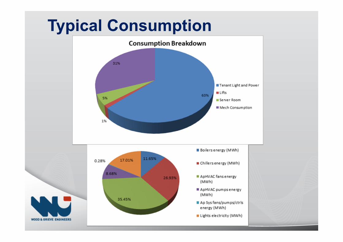
Typical Consumption
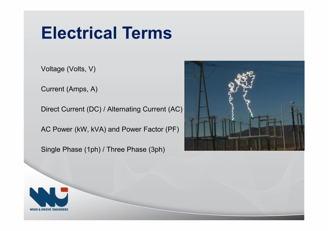
Electrical Terms
Voltage (Volts, V)
Current (Amps, A)
Direct Current (DC) / Alternating Current (AC)
AC Power (kW, kVA) and Power Factor (PF)
Single Phase (1ph) / Three Phase (3ph)
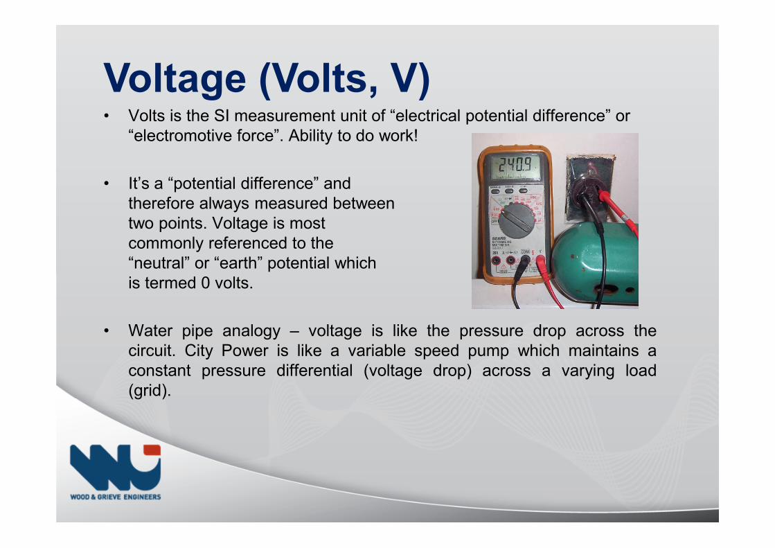
Voltage (Volts, V)• Volts is the SI measurement unit of “electrical potential difference” or
“electromotive force”. Ability to do work!
• It’s a “potential difference” and therefore always measured between two points. Voltage is most commonly referenced to the “neutral” or “earth” potential which is termed 0 volts.
• Water pipe analogy – voltage is like the pressure drop across thecircuit. City Power is like a variable speed pump which maintains aconstant pressure differential (voltage drop) across a varying load(grid).
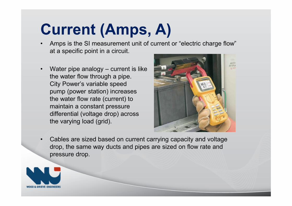
Current (Amps, A)• Amps is the SI measurement unit of current or “electric charge flow”
at a specific point in a circuit.
• Water pipe analogy – current is likethe water flow through a pipe. City Power’s variable speed pump (power station) increases the water flow rate (current) to maintain a constant pressure differential (voltage drop) across the varying load (grid).
• Cables are sized based on current carrying capacity and voltage drop, the same way ducts and pipes are sized on flow rate and pressure drop.
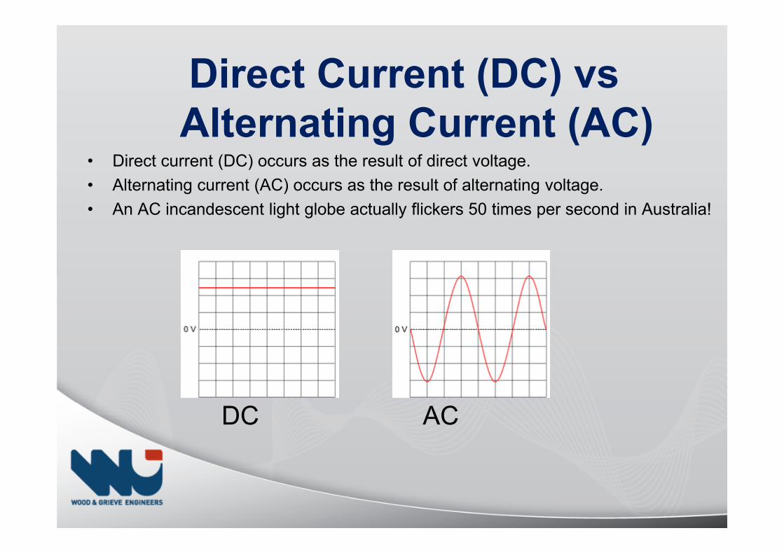
Direct Current (DC) vs
Alternating Current (AC)• Direct current (DC) occurs as the result of direct voltage.
• Alternating current (AC) occurs as the result of alternating voltage.
• An AC incandescent light globe actually flickers 50 times per second in Australia!
DC AC
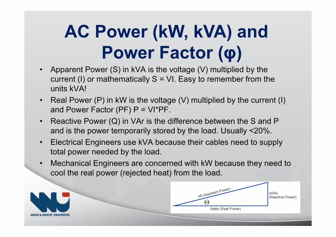
AC Power (kW, kVA) and
Power Factor (φ)• Apparent Power (S) in kVA is the voltage (V) multiplied by the
current (I) or mathematically S = VI. Easy to remember from the units kVA!
• Real Power (P) in kW is the voltage (V) multiplied by the current (I) and Power Factor (PF) P = VI*PF.
• Reactive Power (Q) in VAr is the difference between the S and P and is the power temporarily stored by the load. Usually <20%.
• Electrical Engineers use kVA because their cables need to supply total power needed by the load.
• Mechanical Engineers are concerned with kW because they need to cool the real power (rejected heat) from the load.
Power Factor = 1• Purely “resistive loads” like:
• Heater bank
• Electronic “switch-mode” power supplies (e.g. computer, electronic ballast in a fluoro)
• Variable Speed Drives (electronics)
• Can be usually be switched with less expensive “AC-1” rated contactors as making & breaking currents are less and shorter duration.
ALMOST ANYTHING WHICH THE PREDOMINANT LOAD IS
ELECTRONICS
Power Factor = 0.8• “Inductive loads” like:
• Induction motors (without VSDs)
• Power transformers
• Usually need to be switched with more expensive “AC-3” rated contactors as making & breaking currents are higher due to the inductive characteristic of the load. I.e. causes arcing of the contacts.
ALMOST ANYTHING WHICH HAS WINDINGS
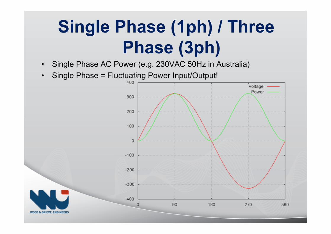
Single Phase (1ph) / Three
Phase (3ph)• Single Phase AC Power (e.g. 230VAC 50Hz in Australia)
• Single Phase = Fluctuating Power Input/Output!
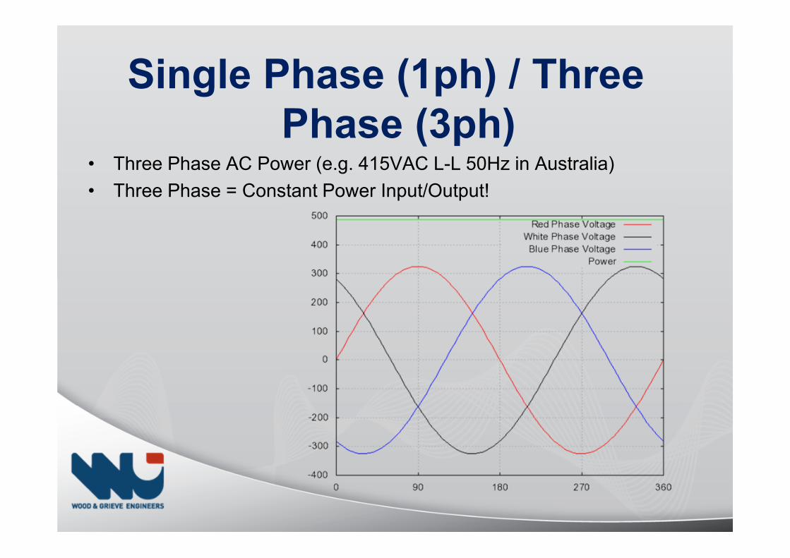
Single Phase (1ph) / Three
Phase (3ph)• Three Phase AC Power (e.g. 415VAC L-L 50Hz in Australia)
• Three Phase = Constant Power Input/Output!
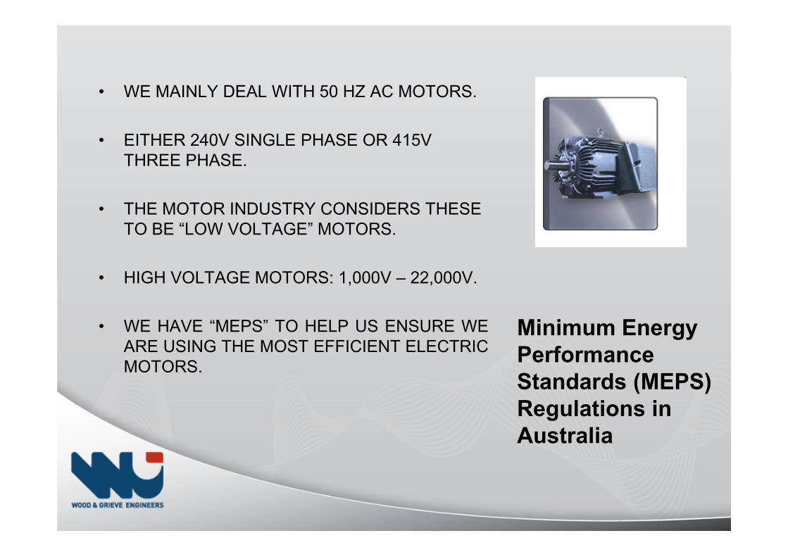
• WE MAINLY DEAL WITH 50 HZ AC MOTORS.
• EITHER 240V SINGLE PHASE OR 415VTHREE PHASE.
• THE MOTOR INDUSTRY CONSIDERS THESE TO BE “LOW VOLTAGE” MOTORS.
• HIGH VOLTAGE MOTORS: 1,000V – 22,000V.
• WE HAVE “MEPS” TO HELP US ENSURE WEARE USING THE MOST EFFICIENT ELECTRICMOTORS.
Minimum Energy
Performance
Standards (MEPS)
Regulations in
Australia
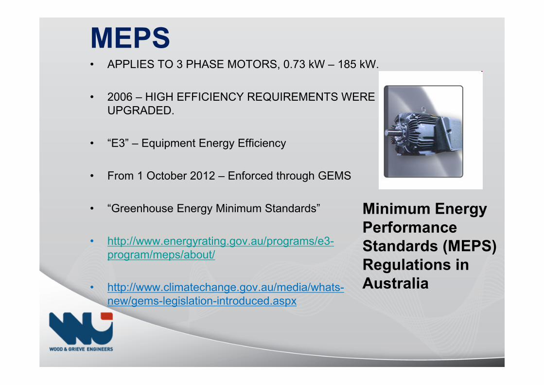
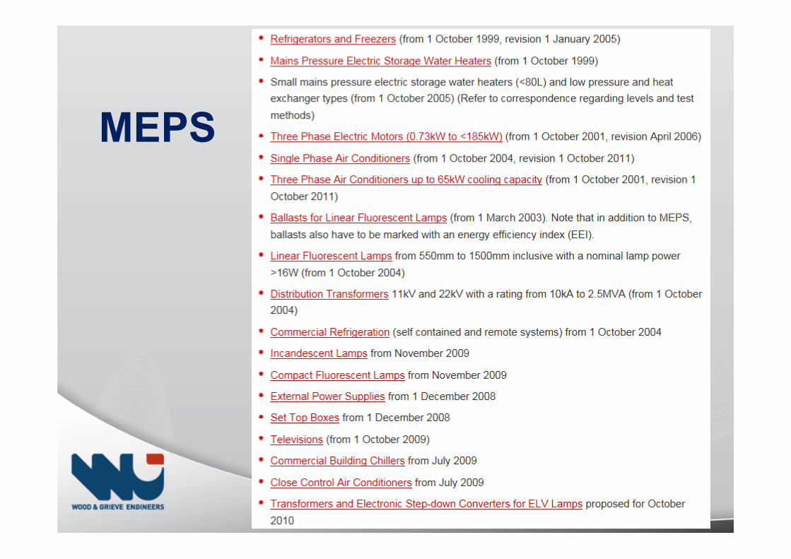
MEPS• APPLIES TO 3 PHASE MOTORS, 0.73 kW – 185 kW.
• 2006 – HIGH EFFICIENCY REQUIREMENTS WERE UPGRADED.
• “E3” – Equipment Energy Efficiency
• From 1 October 2012 – Enforced through GEMS
• “Greenhouse Energy Minimum Standards”
• http://www.energyrating.gov.au/programs/e3-program/meps/about/
• http://www.climatechange.gov.au/media/whats-new/gems-legislation-introduced.aspx
Minimum Energy
Performance
Standards (MEPS)
Regulations in
Australia
MEPS
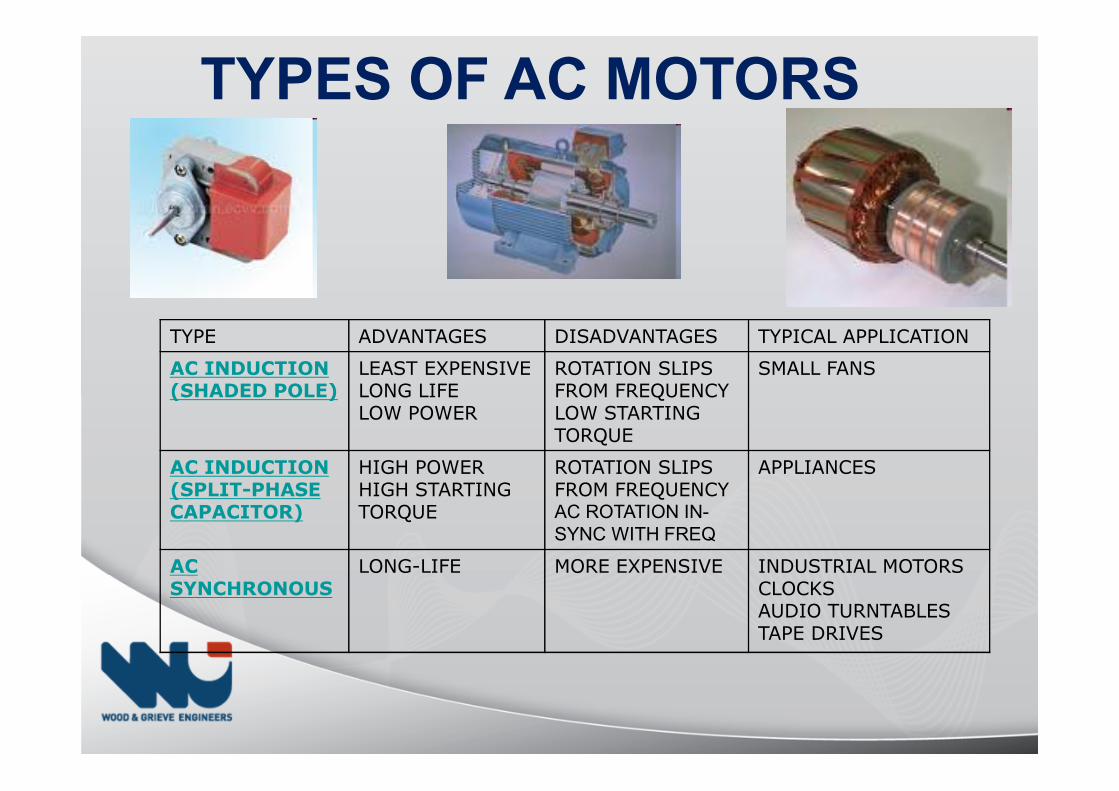
TYPE ADVANTAGES DISADVANTAGES TYPICAL APPLICATION
AC INDUCTION(SHADED POLE)
LEAST EXPENSIVE
LONG LIFE
LOW POWER
ROTATION SLIPS
FROM FREQUENCY
LOW STARTING
TORQUE
SMALL FANS
AC INDUCTION(SPLIT-PHASE CAPACITOR)
HIGH POWER
HIGH STARTING
TORQUE
ROTATION SLIPS
FROM FREQUENCYAC ROTATION IN-SYNC WITH FREQ
APPLIANCES
AC SYNCHRONOUS
LONG-LIFE MORE EXPENSIVE INDUSTRIAL MOTORS
CLOCKS
AUDIO TURNTABLES
TAPE DRIVES
TYPES OF AC MOTORS
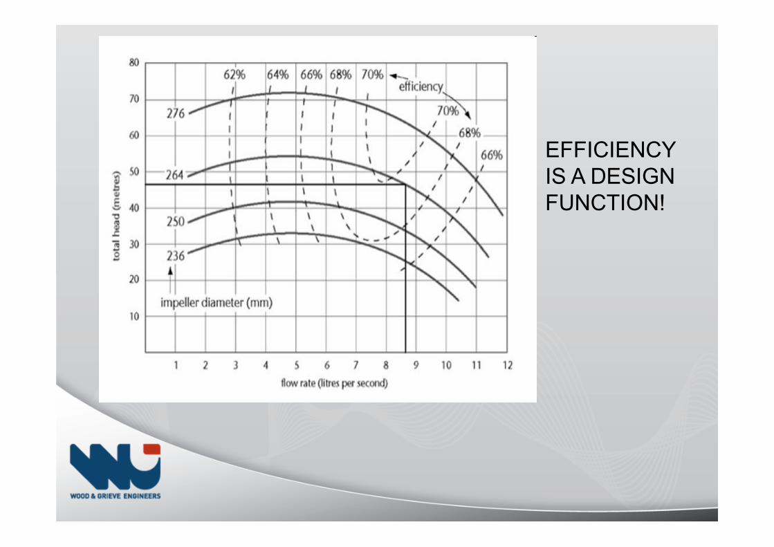
EFFICIENCY IS A DESIGN FUNCTION!
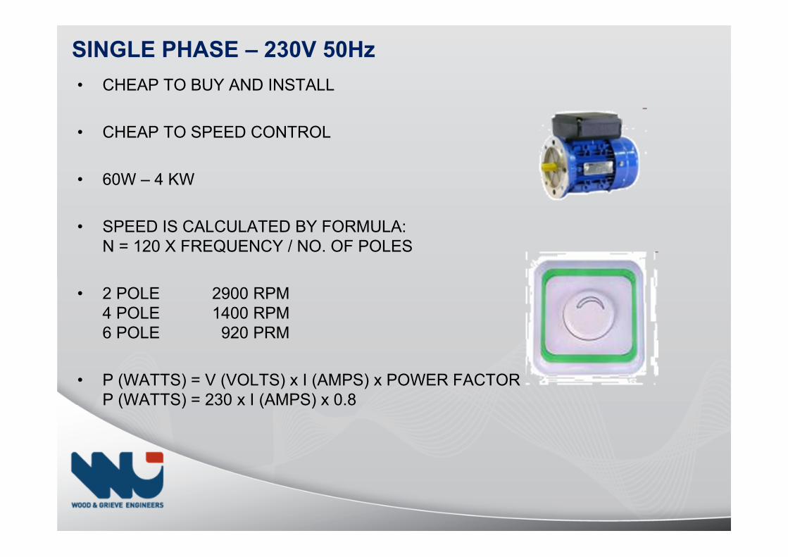
• CHEAP TO BUY AND INSTALL
• CHEAP TO SPEED CONTROL
• 60W – 4 KW
• SPEED IS CALCULATED BY FORMULA:N = 120 X FREQUENCY / NO. OF POLES
• 2 POLE 2900 RPM4 POLE 1400 RPM6 POLE 920 PRM
• P (WATTS) = V (VOLTS) x I (AMPS) x POWER FACTORP (WATTS) = 230 x I (AMPS) x 0.8
SINGLE PHASE – 230V 50Hz
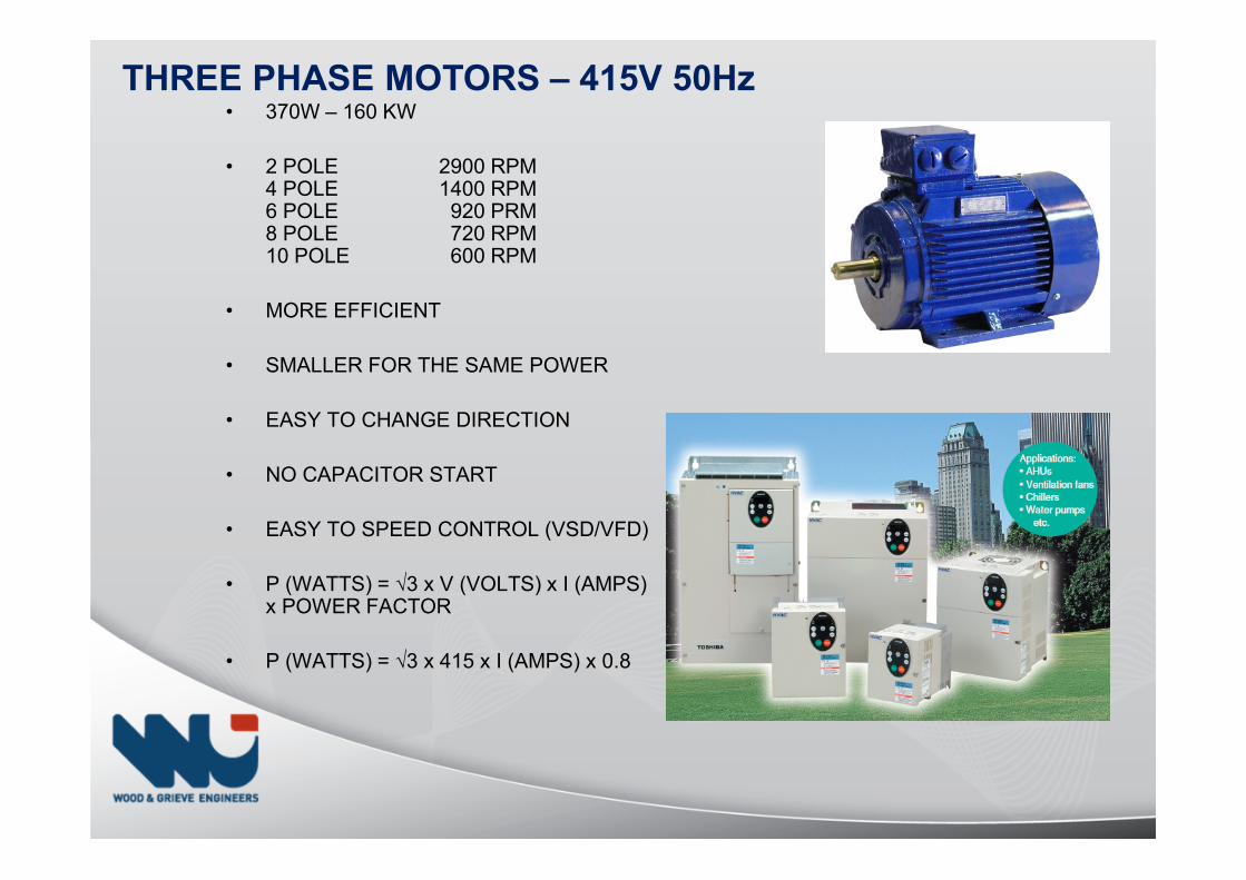
• 370W – 160 KW
• 2 POLE 2900 RPM4 POLE 1400 RPM6 POLE 920 PRM8 POLE 720 RPM10 POLE 600 RPM
• MORE EFFICIENT
• SMALLER FOR THE SAME POWER
• EASY TO CHANGE DIRECTION
• NO CAPACITOR START
• EASY TO SPEED CONTROL (VSD/VFD)
• P (WATTS) = √3 x V (VOLTS) x I (AMPS) x POWER FACTOR
• P (WATTS) = √3 x 415 x I (AMPS) x 0.8
THREE PHASE MOTORS – 415V 50Hz
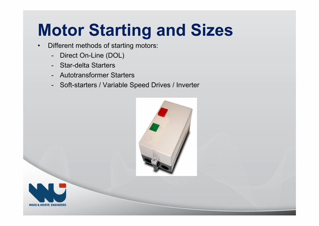
Motor Starting and Sizes• Different methods of starting motors:
- Direct On-Line (DOL)
- Star-delta Starters
- Autotransformer Starters
- Soft-starters / Variable Speed Drives / Inverter
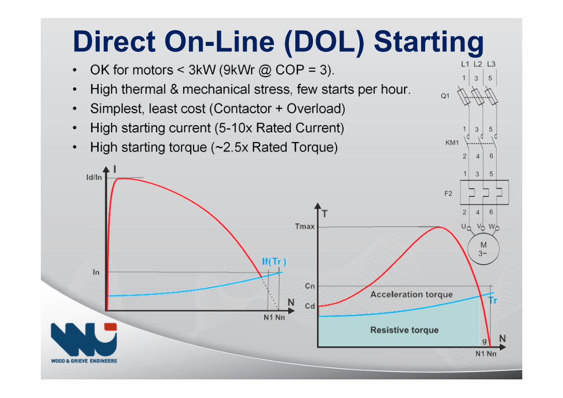
Direct On-Line (DOL) Starting• OK for motors < 3kW (9kWr @ COP = 3).
• High thermal & mechanical stress, few starts per hour.
• Simplest, least cost (Contactor + Overload)
• High starting current (5-10x Rated Current)
• High starting torque (~2.5x Rated Torque)
Star-Delta Starting (Old)• OK for motors < 8kW.
• Lower starting current (2-3x Rated Current)
• Low starting torque (0.2-0.5x Rated Torque)
• Lower thermal stress, 2-3x more starts per hour.
• Doesn’t work for all motors - requires winding terminals.
• Not good when starting on load (e.g. pumps)
Autotransformer Starting (Old)• OK for motors > 8kW.
• Lower starting current (1.7-4x Rated Current)
• Lower starting torque (0.5x Rated Torque)
• Low thermal stress, 3-4x more starts per hour.
• Ramps up voltage in discrete steps – replaced by solid-state Soft Starters and VSDs with almost infinite steps!
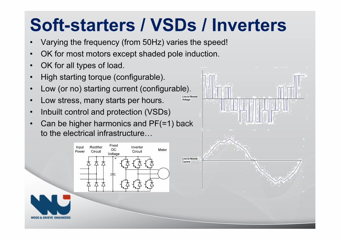
Soft-starters / VSDs / Inverters• Varying the frequency (from 50Hz) varies the speed!
• OK for most motors except shaded pole induction.
• OK for all types of load.
• High starting torque (configurable).
• Low (or no) starting current (configurable).
• Low stress, many starts per hours.
• Inbuilt control and protection (VSDs)
• Can be higher harmonics and PF(=1) backto the electrical infrastructureV
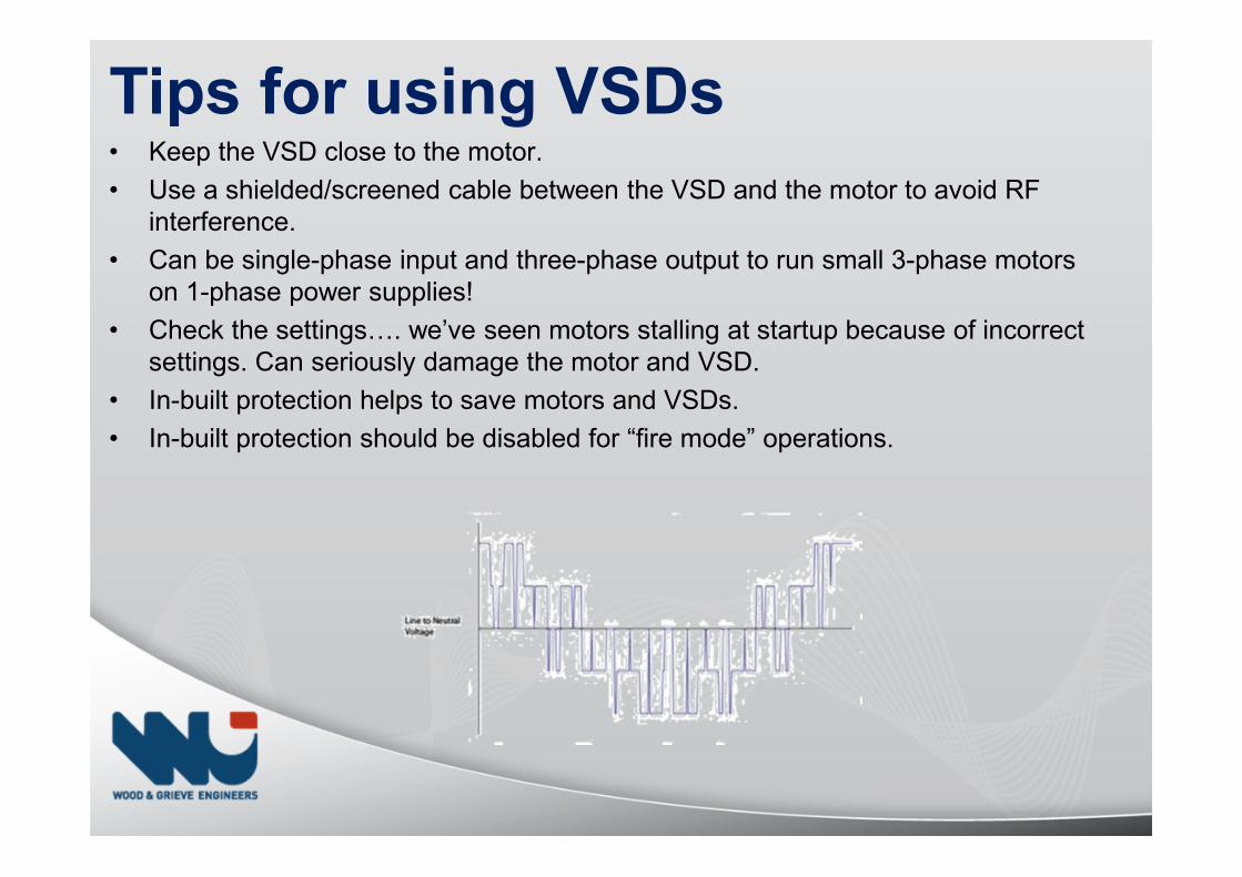
Tips for using VSDs• Keep the VSD close to the motor.
• Use a shielded/screened cable between the VSD and the motor to avoid RF interference.
• Can be single-phase input and three-phase output to run small 3-phase motors on 1-phase power supplies!
• Check the settingsV. we’ve seen motors stalling at startup because of incorrect settings. Can seriously damage the motor and VSD.
• In-built protection helps to save motors and VSDs.
• In-built protection should be disabled for “fire mode” operations.
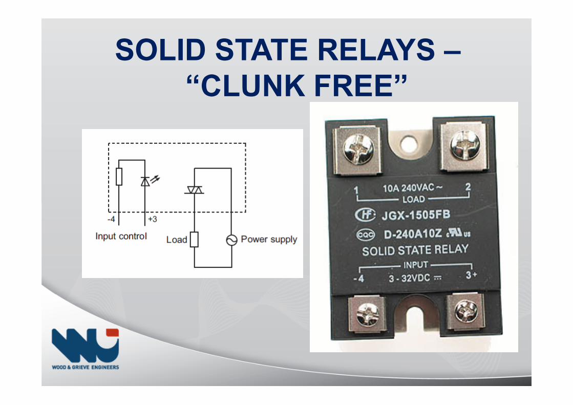
SOLID STATE RELAYS –
“CLUNK FREE”
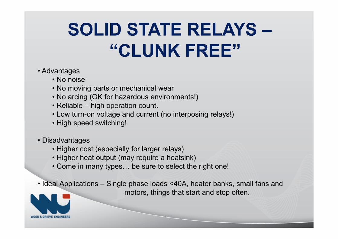
SOLID STATE RELAYS –
“CLUNK FREE”• Advantages
• No noise• No moving parts or mechanical wear• No arcing (OK for hazardous environments!)• Reliable – high operation count.• Low turn-on voltage and current (no interposing relays!)• High speed switching!
• Disadvantages• Higher cost (especially for larger relays)• Higher heat output (may require a heatsink)• Come in many typesV be sure to select the right one!
• Ideal Applications – Single phase loads <40A, heater banks, small fans and motors, things that start and stop often.
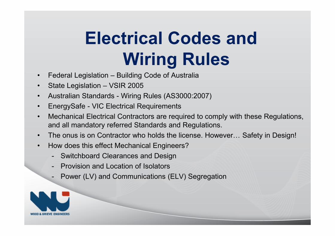
Electrical Codes and
Wiring Rules• Federal Legislation – Building Code of Australia
• State Legislation – VSIR 2005
• Australian Standards - Wiring Rules (AS3000:2007)
• EnergySafe - VIC Electrical Requirements
• Mechanical Electrical Contractors are required to comply with these Regulations, and all mandatory referred Standards and Regulations.
• The onus is on Contractor who holds the license. HoweverV Safety in Design!
• How does this effect Mechanical Engineers?
- Switchboard Clearances and Design
- Provision and Location of Isolators
- Power (LV) and Communications (ELV) Segregation
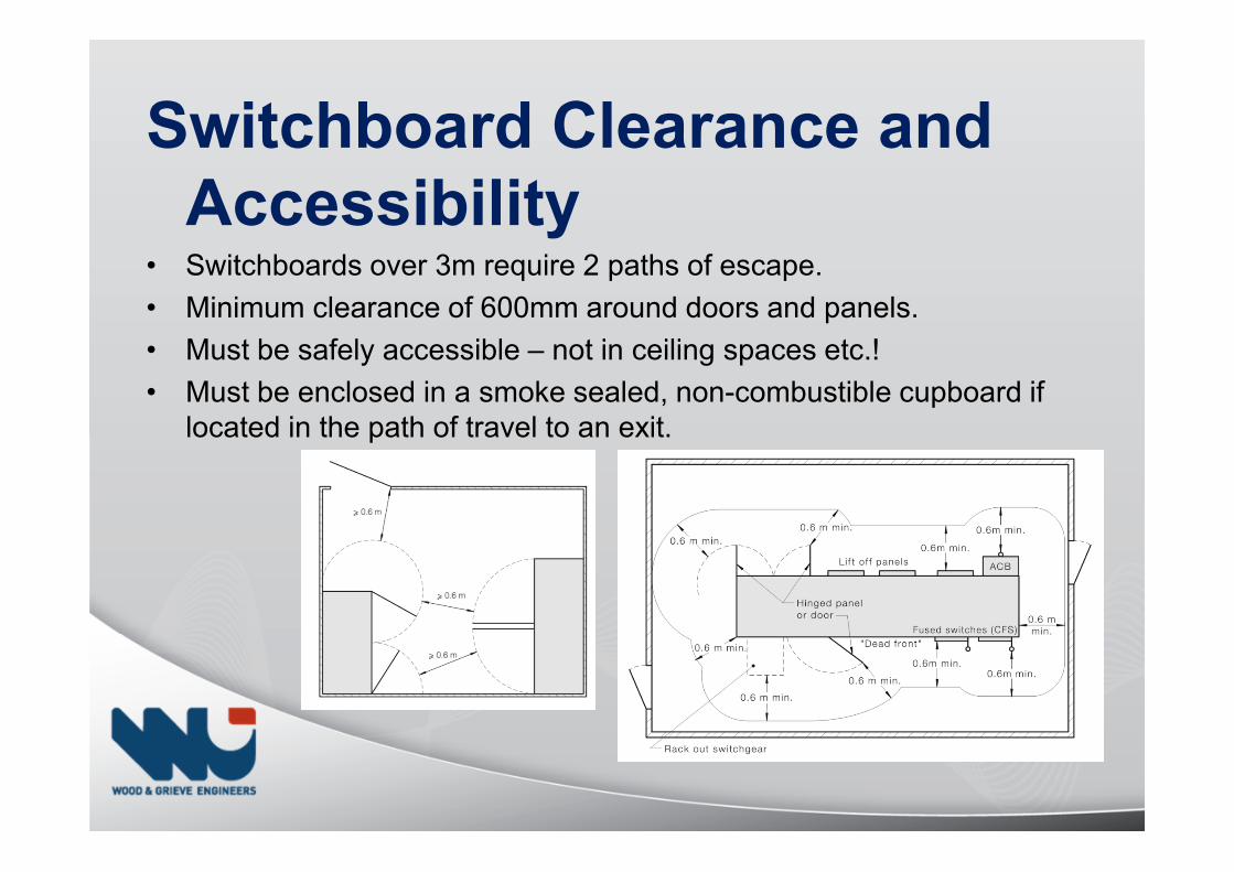
Switchboard Clearance and
Accessibility• Switchboards over 3m require 2 paths of escape.
• Minimum clearance of 600mm around doors and panels.
• Must be safely accessible – not in ceiling spaces etc.!
• Must be enclosed in a smoke sealed, non-combustible cupboard if located in the path of travel to an exit.
• Advise power supply requirements:
- Location
- Volts (Single Phase 240V or Three Phase 415V)
- Amps (Full Load Amps & Starting Amps or kVA and Starting Method)
- Termination Requirements (Cables for MSSB, Isolator or Socket)
- Safety/Essential Requirements (Fire-essential or Generator or both!)
- Understanding of the system operation and power supply diversity!
• Advise communications requirements:
- Location
- Type of communications (e.g. phone line for dialer or ADSL?)
• Advise fire shutdown signal requirements:
- Location (MSSB preferred)
- Type of signal (Zone or General Alarm)
- Fire/AS1668.1 control requirements
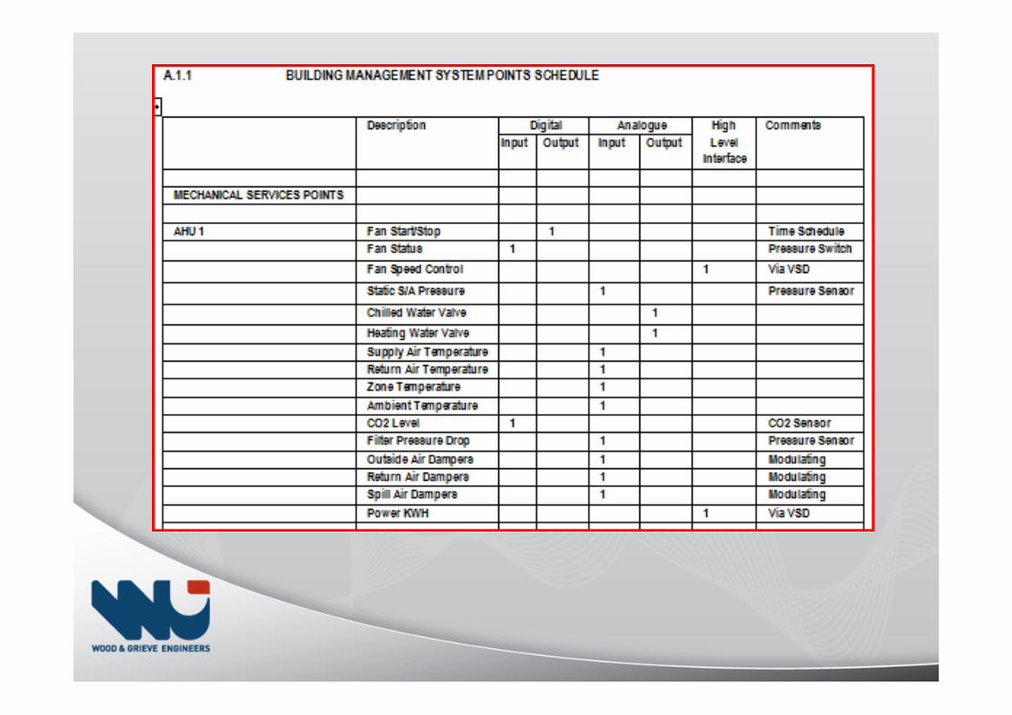
• Request BMS Points including meters and interface type.
Mechanical Consultant to Coordinate:
Electrical Consultant to Coordinate• Confirm power supply requirements are documented. Including confirmation
of the power supply:
- Capacity (e.g. Three Phase 400A)
- Termination details (cable size and entry)
- Fault Level at the MSSB!!
• Advise BMS system & Metering requirements (Points Schedule):
- Location (e.g. Electrical DB location)
- Type of Point (Volt-free contact, Meter Pulse, Meter HLI)
- Meters HLI – Communication Protocol (e.g. MODBUS/LON/N2)
• Pulse-type meters are the past! It’s often best for the Mech-Elec Contractor to supply HLI meters which suit the BMS protocol (Johnson N2/LON/BacNet) for installation by the Electrical Contractor with final programming/ commissioning by the Mech-Elec Contractor!
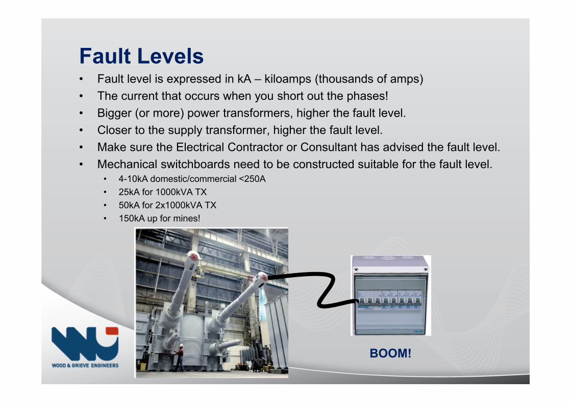
Fault Levels• Fault level is expressed in kA – kiloamps (thousands of amps)
• The current that occurs when you short out the phases!
• Bigger (or more) power transformers, higher the fault level.
• Closer to the supply transformer, higher the fault level.
• Make sure the Electrical Contractor or Consultant has advised the fault level.
• Mechanical switchboards need to be constructed suitable for the fault level.• 4-10kA domestic/commercial <250A
• 25kA for 1000kVA TX
• 50kA for 2x1000kVA TX
• 150kA up for mines!
BOOM!
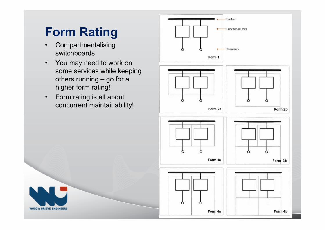
Form Rating• Compartmentalising
switchboards
• You may need to work on some services while keeping others running – go for a higher form rating!
• Form rating is all about concurrent maintainability!
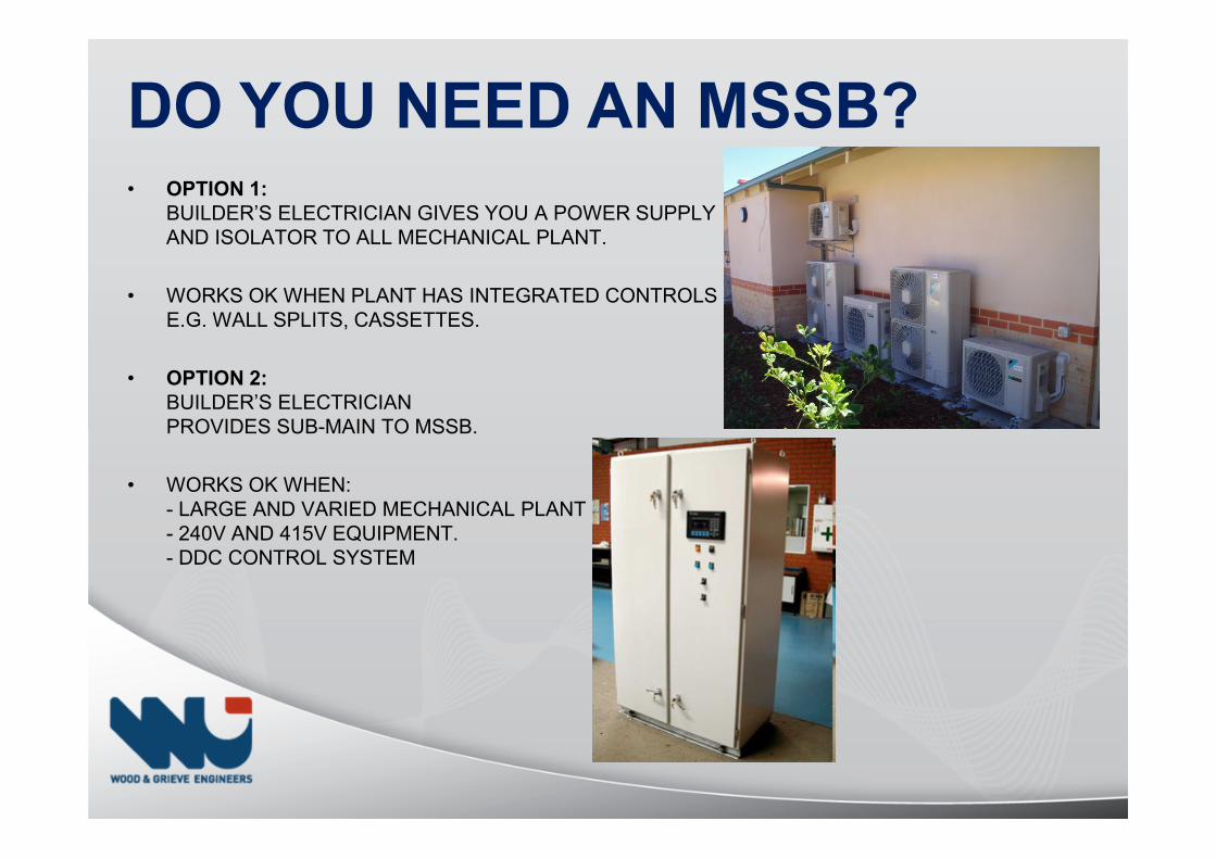
DO YOU NEED AN MSSB?• OPTION 1:
BUILDER’S ELECTRICIAN GIVES YOU A POWER SUPPLY AND ISOLATOR TO ALL MECHANICAL PLANT.
• WORKS OK WHEN PLANT HAS INTEGRATED CONTROLS E.G. WALL SPLITS, CASSETTES.
• OPTION 2:
BUILDER’S ELECTRICIANPROVIDES SUB-MAIN TO MSSB.
• WORKS OK WHEN:- LARGE AND VARIED MECHANICAL PLANT- 240V AND 415V EQUIPMENT.- DDC CONTROL SYSTEM
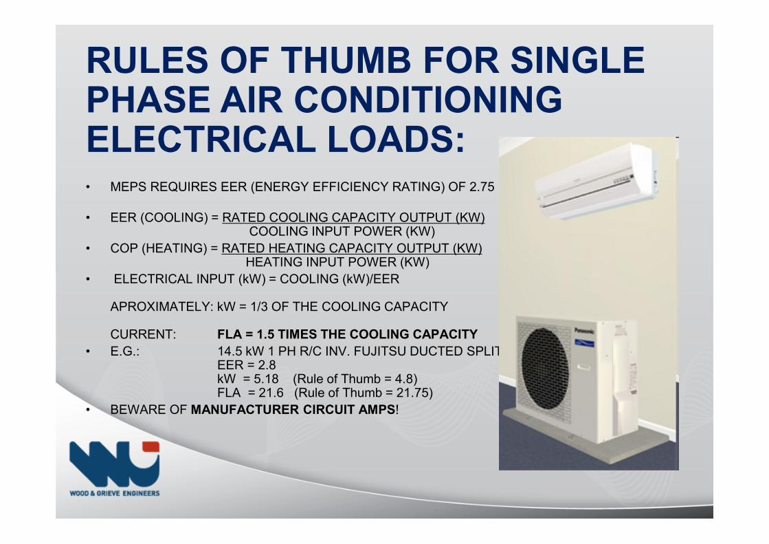
RULES OF THUMB FOR SINGLE PHASE AIR CONDITIONING ELECTRICAL LOADS:• MEPS REQUIRES EER (ENERGY EFFICIENCY RATING) OF 2.75
• EER (COOLING) = RATED COOLING CAPACITY OUTPUT (KW)COOLING INPUT POWER (KW)
• COP (HEATING) = RATED HEATING CAPACITY OUTPUT (KW)HEATING INPUT POWER (KW)
• ELECTRICAL INPUT (kW) = COOLING (kW)/EER
APROXIMATELY: kW = 1/3 OF THE COOLING CAPACITY
CURRENT: FLA = 1.5 TIMES THE COOLING CAPACITY
• E.G.: 14.5 kW 1 PH R/C INV. FUJITSU DUCTED SPLITEER = 2.8kW = 5.18 (Rule of Thumb = 4.8)FLA = 21.6 (Rule of Thumb = 21.75)
• BEWARE OF MANUFACTURER CIRCUIT AMPS!
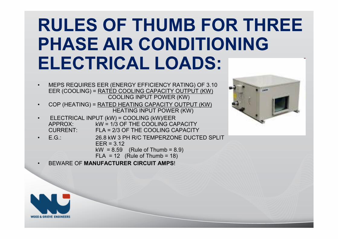
RULES OF THUMB FOR THREE PHASE AIR CONDITIONING ELECTRICAL LOADS:• MEPS REQUIRES EER (ENERGY EFFICIENCY RATING) OF 3.10
EER (COOLING) = RATED COOLING CAPACITY OUTPUT (KW)COOLING INPUT POWER (KW)
• COP (HEATING) = RATED HEATING CAPACITY OUTPUT (KW)HEATING INPUT POWER (KW)
• ELECTRICAL INPUT (kW) = COOLING (kW)/EERAPPROX: kW = 1/3 OF THE COOLING CAPACITYCURRENT: FLA = 2/3 OF THE COOLING CAPACITY
• E.G.: 26.8 kW 3 PH R/C TEMPERZONE DUCTED SPLITEER = 3.12kW = 8.59 (Rule of Thumb = 8.9)FLA = 12 (Rule of Thumb = 18)
• BEWARE OF MANUFACTURER CIRCUIT AMPS!
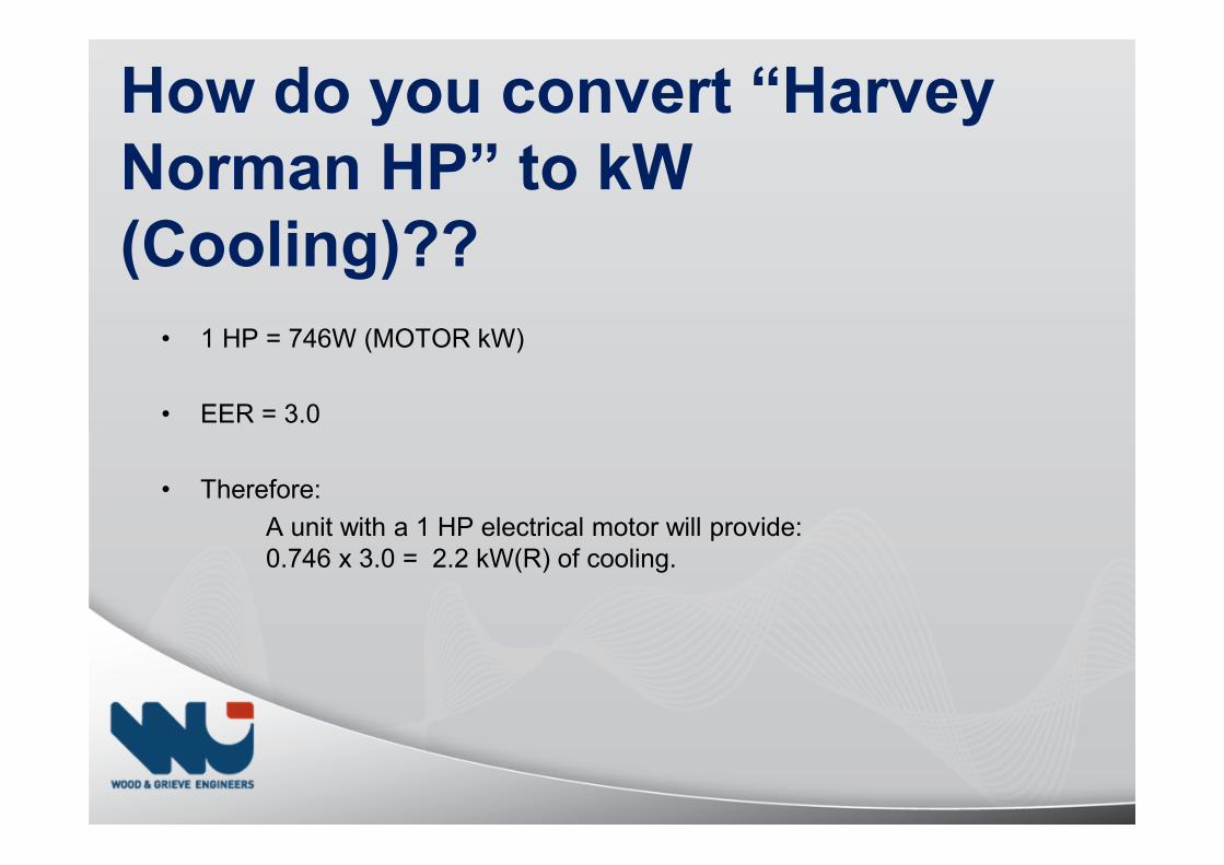
• 1 HP = 746W (MOTOR kW)
• EER = 3.0
• Therefore:
A unit with a 1 HP electrical motor will provide:0.746 x 3.0 = 2.2 kW(R) of cooling.
How do you convert “Harvey
Norman HP” to kW
(Cooling)??
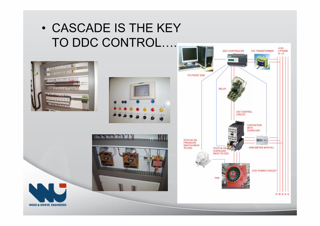
• CASCADE IS THE KEYTO DDC CONTROLV..
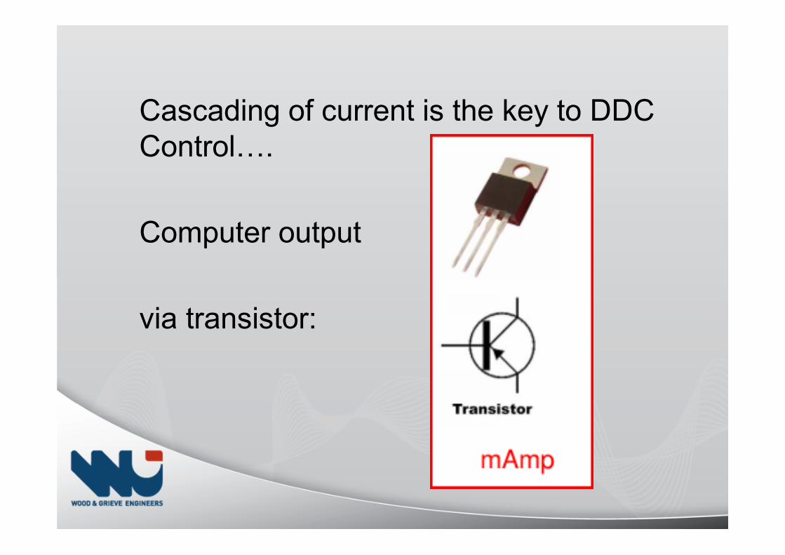
Cascading of current is the key to DDCControlV.
Computer output
via transistor:
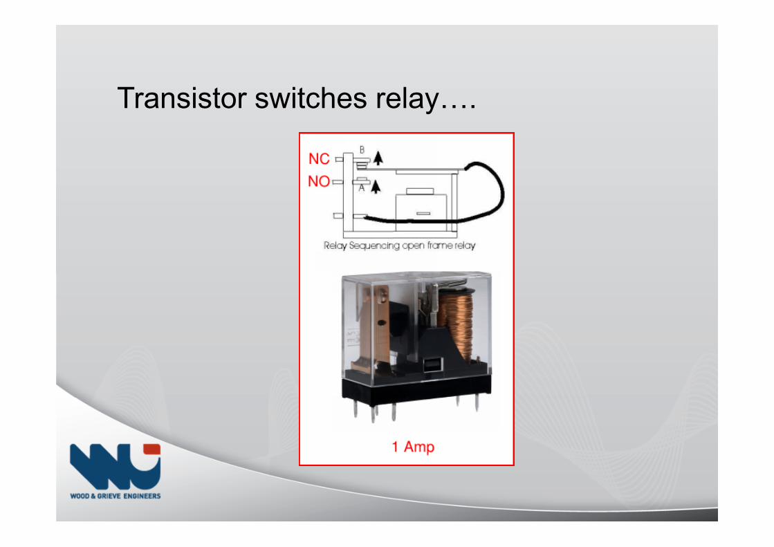
Transistor switches relayV.
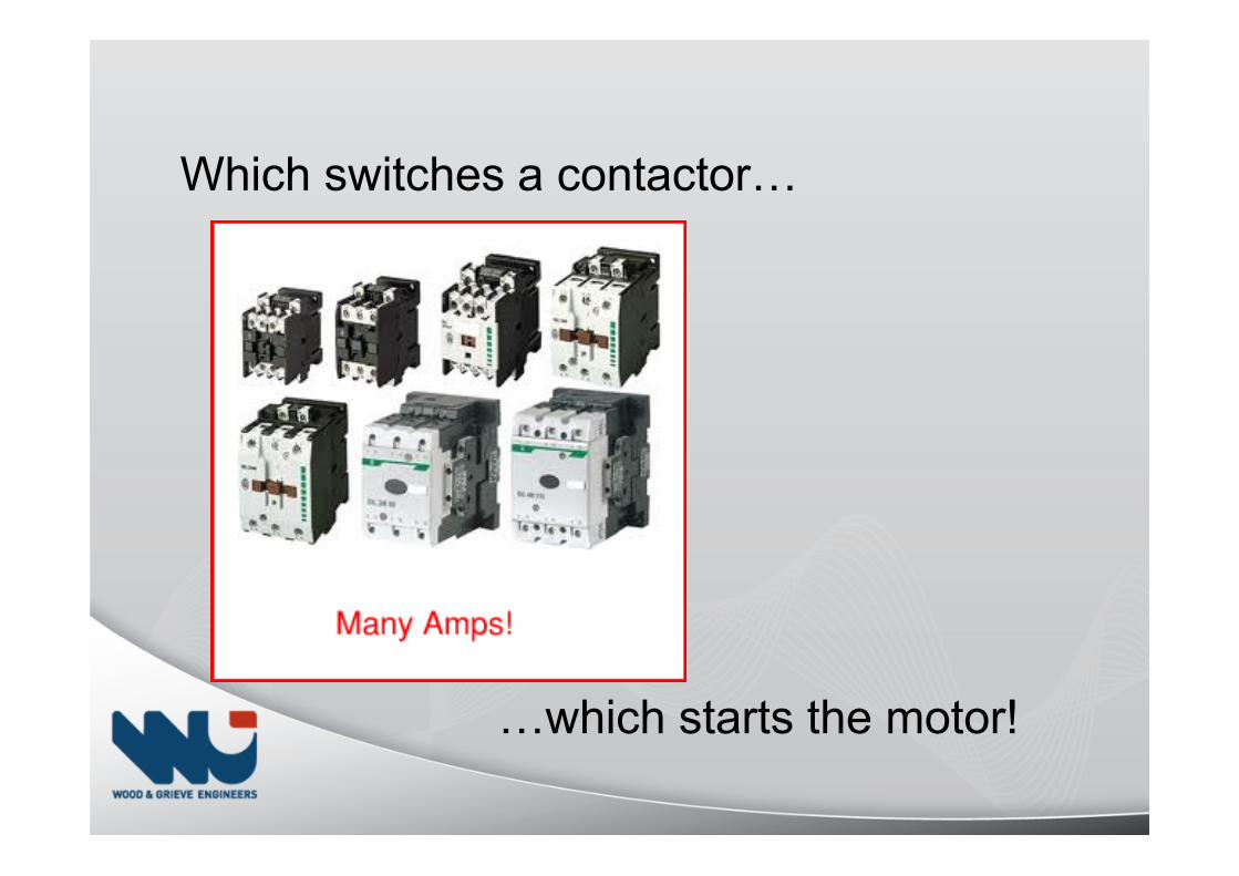
Which switches a contactorV
Vwhich starts the motor!
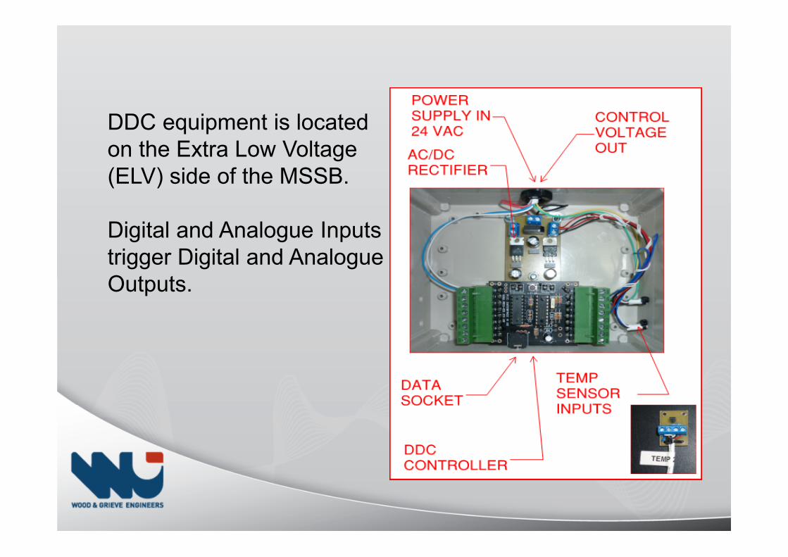
DDC equipment is locatedon the Extra Low Voltage(ELV) side of the MSSB.
Digital and Analogue Inputstrigger Digital and AnalogueOutputs.
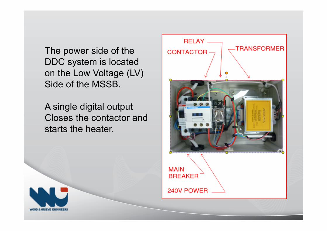
The power side of theDDC system is locatedon the Low Voltage (LV)Side of the MSSB.
A single digital outputCloses the contactor andstarts the heater.
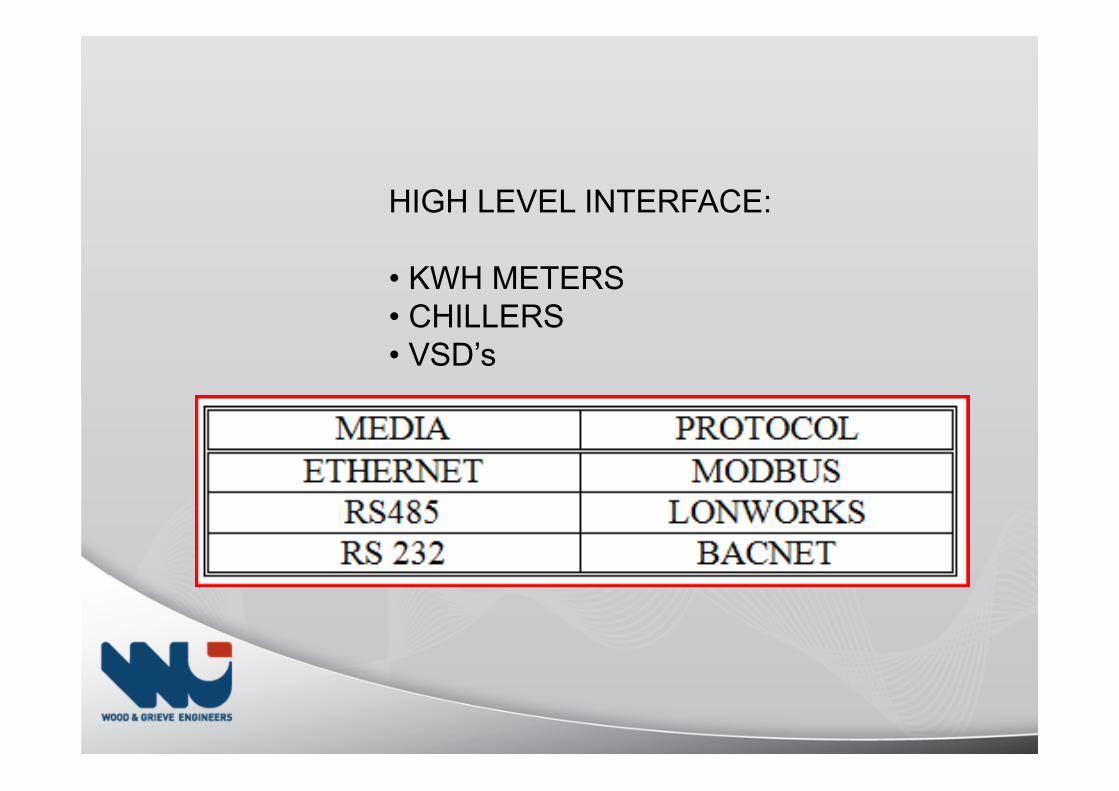
HIGH LEVEL INTERFACE:
• KWH METERS• CHILLERS• VSD’s

Thank you