Embed Size (px)
Citation preview
Electrical Essentials for HVAC&R Engineers
Wednesday, October 7
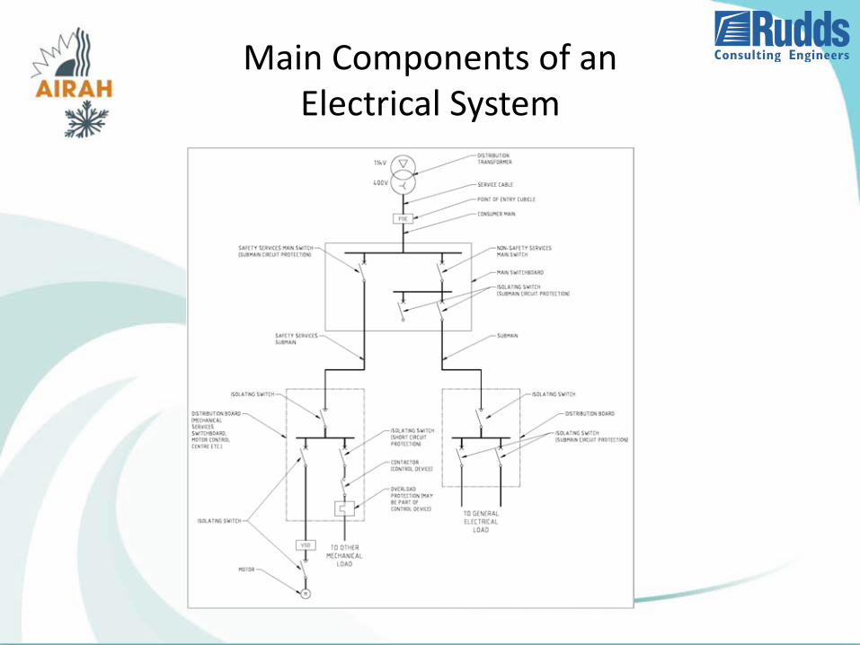
Main Components of an Electrical System
Accessibility of Switchboards
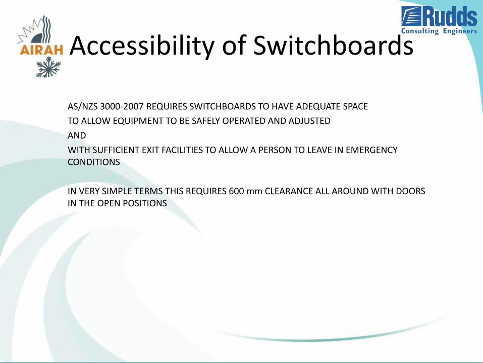
AS/NZS 3000-2007 REQUIRES SWITCHBOARDS TO HAVE ADEQUATE SPACE
TO ALLOW EQUIPMENT TO BE SAFELY OPERATED AND ADJUSTED
AND
WITH SUFFICIENT EXIT FACILITIES TO ALLOW A PERSON TO LEAVE IN EMERGENCY CONDITIONS
IN VERY SIMPLE TERMS THIS REQUIRES 600 mm CLEARANCE ALL AROUND WITH DOORS IN THE OPEN POSITIONS
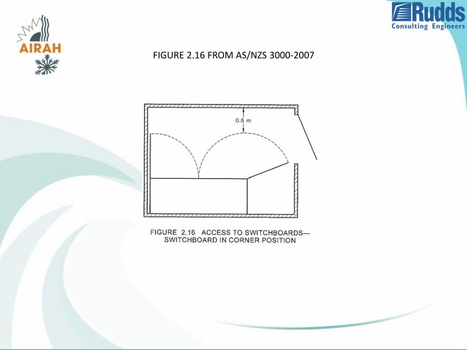
FIGURE 2.16 FROM AS/NZS 3000-2007
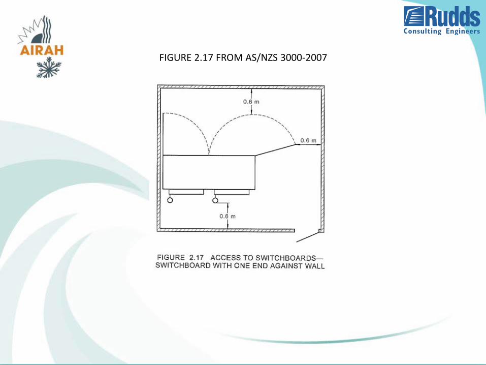
FIGURE 2.17 FROM AS/NZS 3000-2007
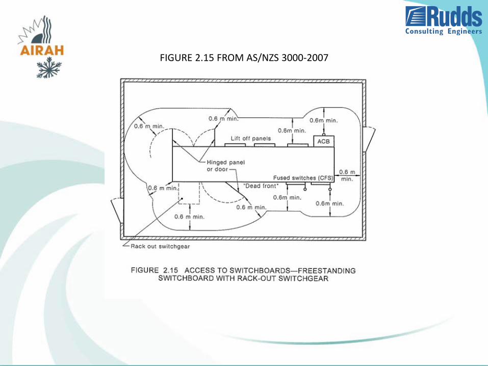
FIGURE 2.15 FROM AS/NZS 3000-2007
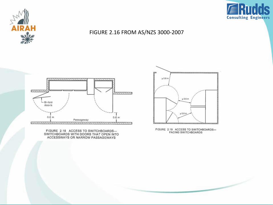
FIGURE 2.16 FROM AS/NZS 3000-2007
Large Switchboards
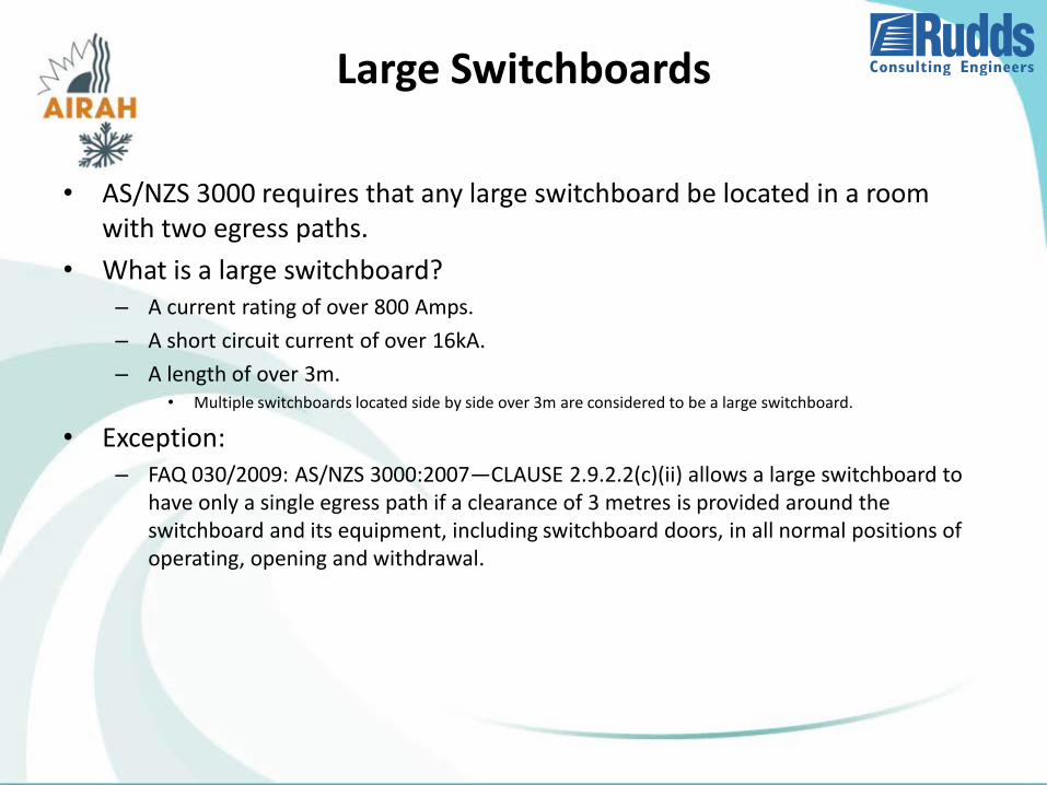
• AS/NZS 3000 requires that any large switchboard be located in a room with two egress paths.
• What is a large switchboard?– A current rating of over 800 Amps.
– A short circuit current of over 16kA.
– A length of over 3m.• Multiple switchboards located side by side over 3m are considered to be a large switchboard.
• Exception:– FAQ 030/2009: AS/NZS 3000:2007—CLAUSE 2.9.2.2(c)(ii) allows a large switchboard to
have only a single egress path if a clearance of 3 metres is provided around the switchboard and its equipment, including switchboard doors, in all normal positions of operating, opening and withdrawal.
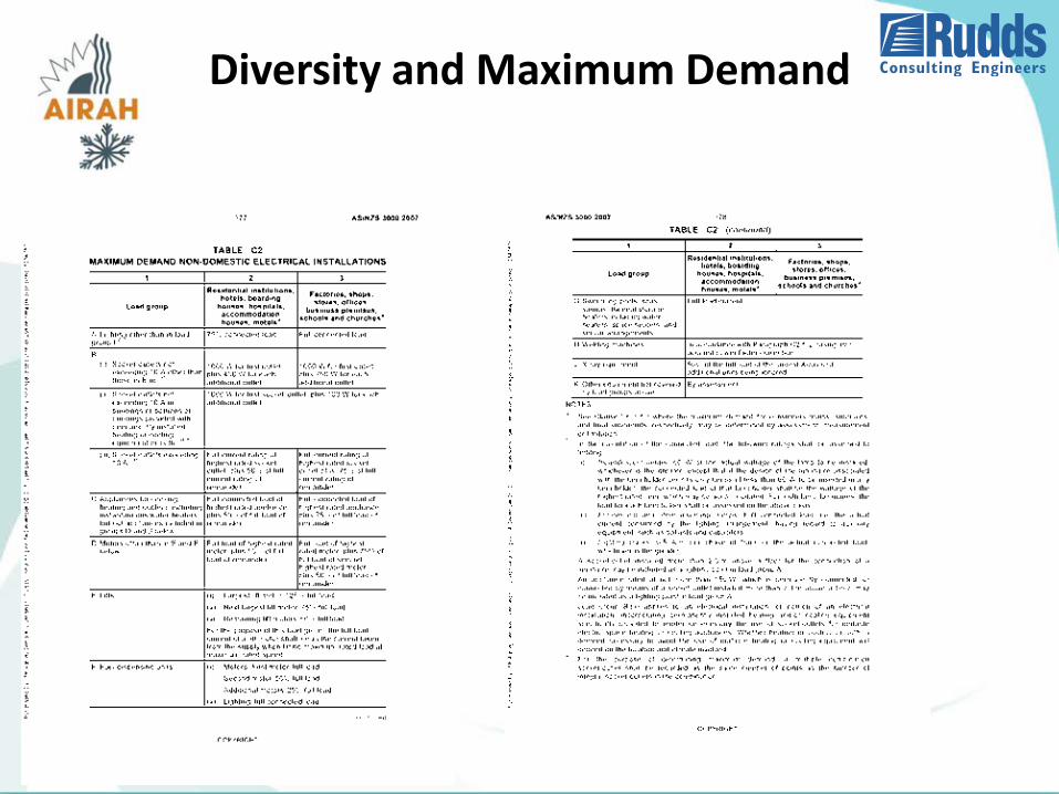
Diversity and Maximum Demand
• What is diversity?– Diversity is an allowance that all connected equipment will not operate at full load at
the same time.
• Maximum Demand is the sum of the connected loads with diversity applied.
• How to determine diversity?– AS/NZS 3000 Table C2 provides diversity calculations.
Diversity and Maximum Demand
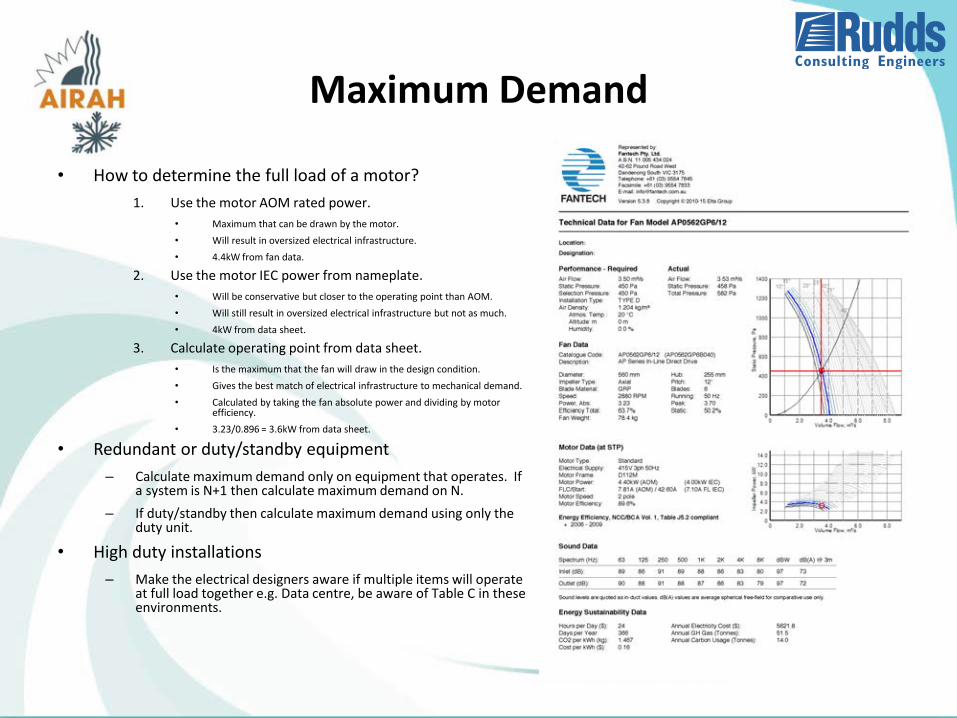
Maximum Demand
• How to determine the full load of a motor?
1. Use the motor AOM rated power.
• Maximum that can be drawn by the motor.
• Will result in oversized electrical infrastructure.
• 4.4kW from fan data.
2. Use the motor IEC power from nameplate.
• Will be conservative but closer to the operating point than AOM.
• Will still result in oversized electrical infrastructure but not as much.
• 4kW from data sheet.
3. Calculate operating point from data sheet.
• Is the maximum that the fan will draw in the design condition.
• Gives the best match of electrical infrastructure to mechanical demand.
• Calculated by taking the fan absolute power and dividing by motor efficiency.
• 3.23/0.896 = 3.6kW from data sheet.
• Redundant or duty/standby equipment
– Calculate maximum demand only on equipment that operates. If a system is N+1 then calculate maximum demand on N.
– If duty/standby then calculate maximum demand using only the duty unit.
• High duty installations
– Make the electrical designers aware if multiple items will operate at full load together e.g. Data centre, be aware of Table C in these environments.
Voltage Drop
• What is voltage drop?
– The reduction in voltage caused by current flow in the cables.
• Determined by ohms law, V = IR.
• Also dependent on power factor, typically lower power factor gives higher voltage drop.
• Why is voltage drop a problem?
– AS/NZS 3000 mandates maximum voltage drop of either 5% or 7%.
• 5% for shared and off-site substations.
• 7% for dedicated on-site substations.
– Can stop DOL or delta-star motors from starting.
• Too high a volt drop results in insufficient torque to start the motor.
• DOL motors in particular have high starting current and low power factor resulting in high volt drop.
• Correct voltage drop calculations require a knowledge of the entire electrical system from the substation to the load. Can be a problem for mechanical contractors if the electrical data is not provided.
Harmonics
• What are harmonics?
– Higher frequency components that add together to create a distorted waveform.
• Are always multiples of the fundamental frequency of 50Hz.
• Usually referred to by their harmonic number.
– 3rd harmonic = 3 x 50Hz = 150Hz
– 4th harmonic = 4 x 50Hz = 200Hz
– 5th harmonic = 5 x 50Hz = 250Hz etc.
• Usually only odd numbered harmonics are present; 3, 5, 7, 9 etc.
• Why are harmonics a problem?
– High frequency components cause excessive power loss and heating in motors, capacitors, transformers etc.
– Triplen harmonics (multiples of 3 such as 3, 9, 15 etc.) add in neutral cables and can cause overloads.
Harmonics
• What are the sources of harmonics?
– VSDs are the number one source of harmonics in a typical building.
VSD Design Best Practice 26 May 2014 | 48
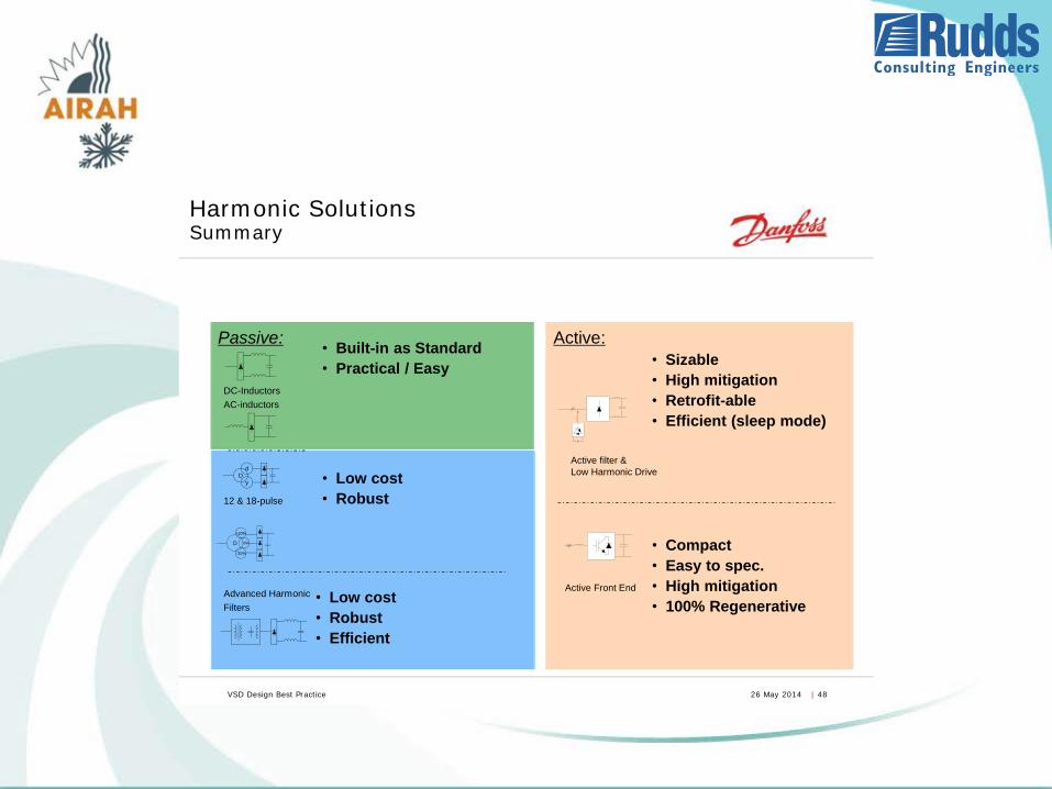
Passive:
DC-Inductors AC-inductors
Advanced Harmonic Filters
Active:
///
Active Front End
/// ///
Active filter & Low Harmonic Drive
Harmonic Solutions Summary
Dd
y
D
-20%
+20%
0%
12 & 18-pulse
• Built-in as Standard • Practical / Easy
• Low cost • Robust
• Low cost • Robust • Efficient
• Sizable • High mitigation • Retrofit-able • Efficient (sleep mode)
• Compact • Easy to spec. • High mitigation • 100% Regenerative
VSD Design Best Practice 26 May 2014 | 4
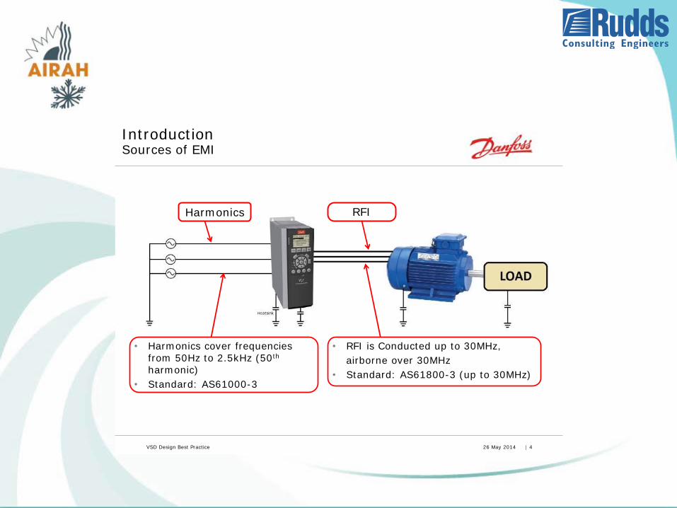
Introduction Sources of EMI
Harmonics RFI
• RFI is Conducted up to 30MHz, airborne over 30MHz • Standard: AS61800-3 (up to 30MHz)
• Harmonics cover frequencies from 50Hz to 2.5kHz (50th harmonic)
• Standard: AS61000-3
VSD Design Best Practice 26 May 2014 | 10
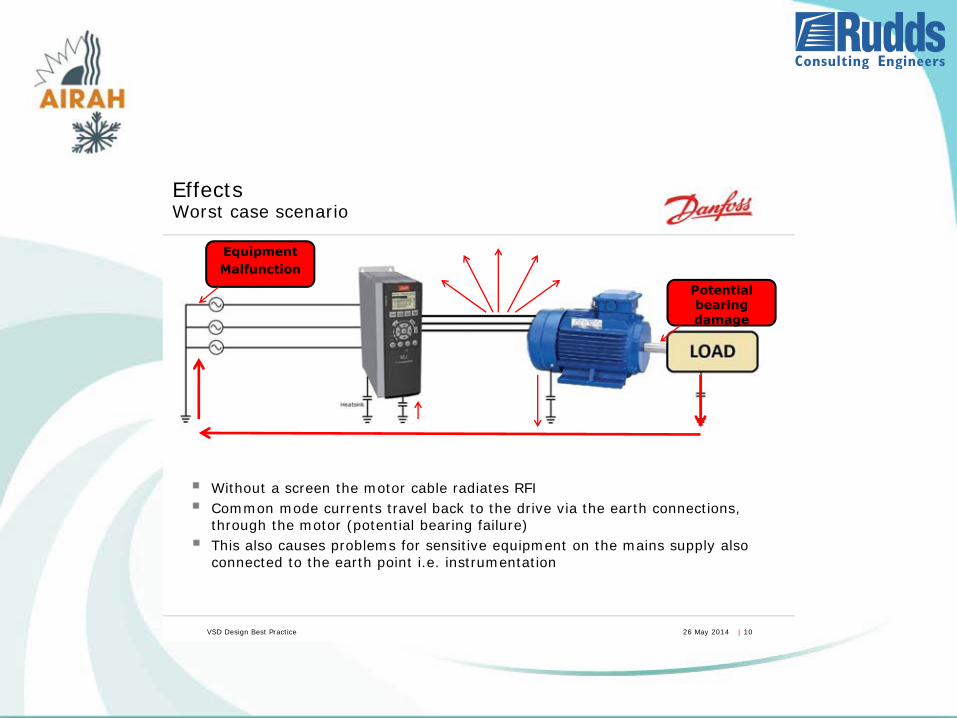
Effects Worst case scenario
Without a screen the motor cable radiates RFI Common mode currents travel back to the drive via the earth connections, through the motor (potential bearing failure) This also causes problems for sensitive equipment on the mains supply also connected to the earth point i.e. instrumentation
Potential bearing damage
Equipment Malfunction
VSD Design Best Practice 26 May 2014 | 15
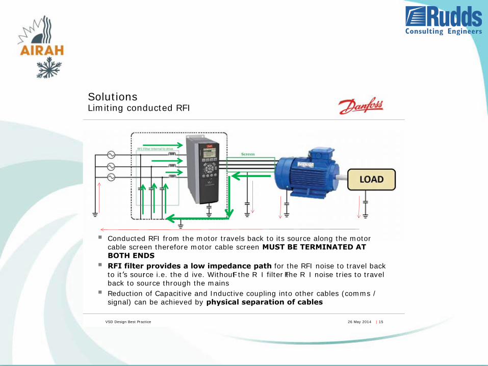
Solutions Limiting conducted RFI
Conducted RFI from the motor travels back to its source along the motor cable screen therefore motor cable screen MUST BE TERMINATED AT BOTH ENDS RFI filter provides a low impedance path for the RFI noise to travel back to it’s source i.e. the dr ive. Without the RF I filter the RF I noise tries to travel back to source through the mains Reduction of Capacitive and Inductive coupling into other cables (comms / signal) can be achieved by physical separation of cables
VSD Design Best Practice 26 May 2014 | 16
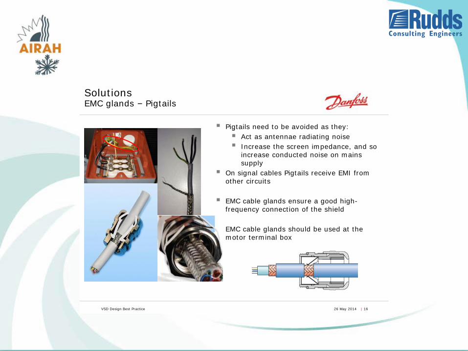
Solutions EMC glands – Pigtails
Pigtails need to be avoided as they: gAct as antennae radiating noise Increase the screen impedance, and so increase conducted noise on mains supply
On signal cables Pigtails receive EMI from other circuits EMC cable glands ensure a good high- frequency connection of the shield EMC cable glands should be used at the motor terminal box
VSD Design Best Practice 26 May 2014 | 20
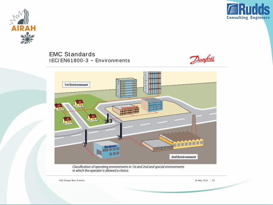
EMC Standards IEC/EN61800-3 – Environments
VSD Design Best Practice 26 May 2014 | 21
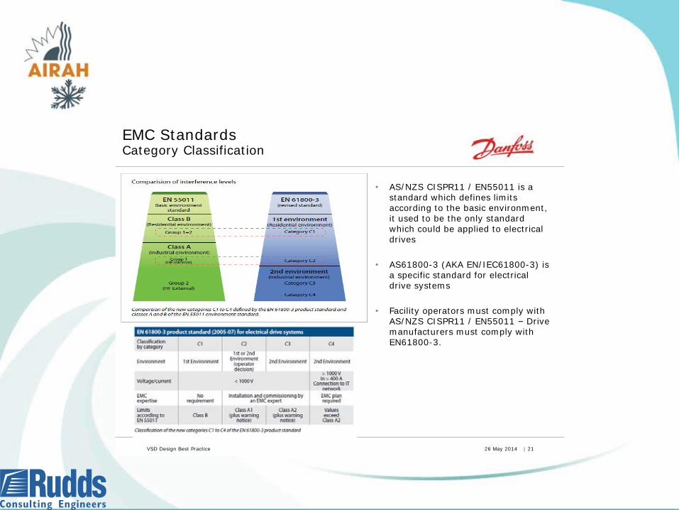
• AS/NZS CISPR11 / EN55011 is a standard which defines limits according to the basic environment, it used to be the only standard which could be applied to electrical drives
• AS61800-3 (AKA EN/IEC61800-3) is a specific standard for electrical drive systems
• Facility operators must comply with AS/NZS CISPR11 / EN55011 – Drive manufacturers must comply with EN61800-3.
EMC Standards Category Classification
Earthing
• What is earthing?
– The connection of the general electrical installation to the ground.
• Why earth the electrical system?
– To protect against indirect contact by the automatic disconnection of supply.
• Indirect contact is contact with conductive parts that are not normally live but may become live in a fault situation such as a phase to earth fault.
• Automatic disconnection of supply is the tripping of a protective device such as a circuit breaker or fuse by the current produced by a phase to earth fault (earth fault loop).
• How is the electrical system earthed?
– By a continuous conductor connected to the exposed conductive part to an earth stake or earth mat.
– By the connection of the electrical system neutral conductor to earth at a single point in the electrical installation (MEN link).
• Equipotential bonding
– Electrical connections intended to bring exposed conductive parts or extraneous conductive parts to the same or approximately the same potential, but not intended to carry current in normal service.
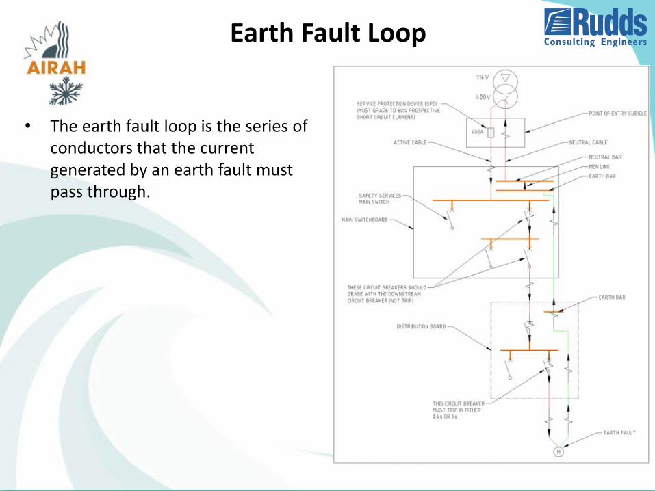
Earth Fault Loop
• The earth fault loop is the series of conductors that the current generated by an earth fault must pass through.
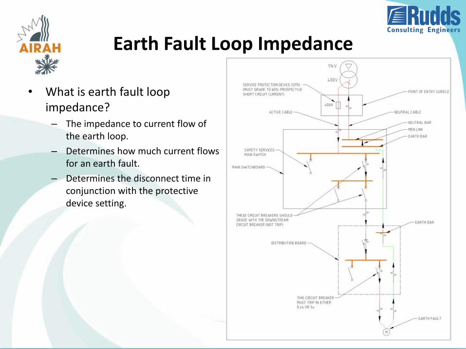
Earth Fault Loop Impedance
• What is earth fault loop impedance?– The impedance to current flow of
the earth loop.
– Determines how much current flows for an earth fault.
– Determines the disconnect time in conjunction with the protective device setting.
Earth Fault Loop Disconnect Times
• AS/NZS 3000 mandates disconnect times for various parts of the electrical installation.
• An earth fault must be disconnected within 0.4s (400ms) for:
– Socket-outlets having rated currents not exceeding 63 A; or
– hand-held Class I equipment (equipment have a conductive outer case connected to earth); or
– (iii) portable equipment intended for manual movement during use.
• An earth fault must be disconnected within 5s for all other equipment.
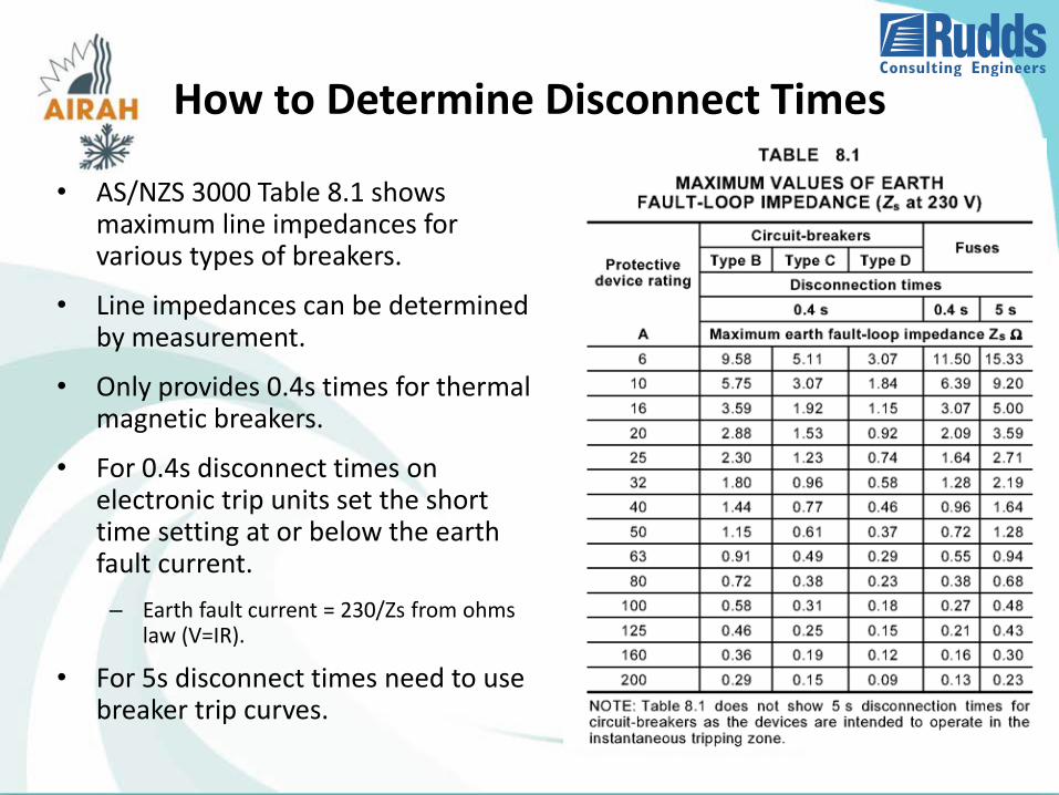
How to Determine Disconnect Times
• AS/NZS 3000 Table 8.1 shows maximum line impedances for various types of breakers.
• Line impedances can be determined by measurement.
• Only provides 0.4s times for thermal magnetic breakers.
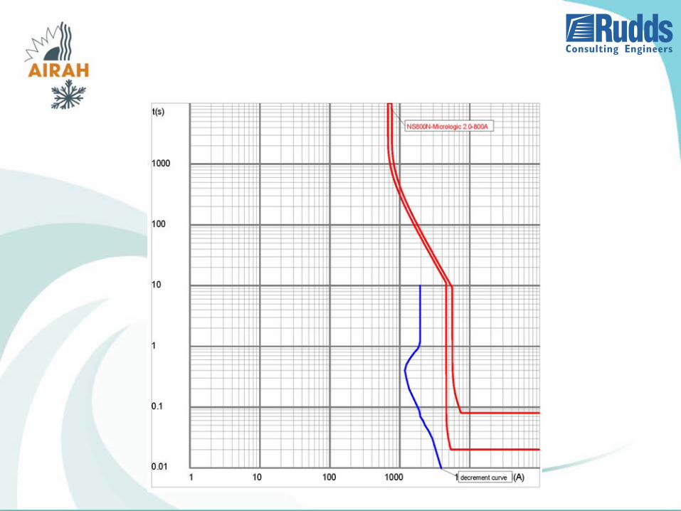
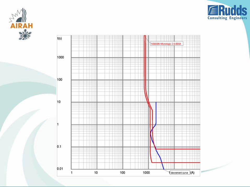
• For 0.4s disconnect times on electronic trip units set the short time setting at or below the earth fault current.
– Earth fault current = 230/Zs from ohms law (V=IR).
• For 5s disconnect times need to use breaker trip curves.
Overload and Short-circuit Protection
• AS/NZS 3000 requires that all cables be protected against both over load and short-circuit.
• Overload and short circuit protection may be combined in a device (circuit breaker or fuse) or by separate devices (thermal overload and circuit breaker or fuse).
• Overload protection is usually provided at the start of the cable but may be provided at the end under certain conditions (AS/NZS 3000 clause 2.5.3.3) or even omitted (AS/NZS 3000 clause 2.5.3.4).
• Short-circuit protection is provided at the start of the cable but may be provided within 3m of the start of the cable under certain conditions (AS/NZS 3000 clause 2.5.4.3) or even omitted (AS/NZS 3000 clause 2.5.4.4).
Protection Grading and Discrimination
• What is protection grading?
Protection grading is ensuring that the protective device closest to the overload and short-circuit disconnects first to minimise the impact of the fault on the electrical system.
Discrimination, selectivity and protection grading all describe the same thing.
• Total discrimination
Total discrimination is when a smaller protective device is guaranteed to operate before a larger protective device under any circumstance.
Only achievable by manufacturer’s test between devices of the same manufacturer.
• Deemed Discrimination
AS/NZS 3000 clause 2.5.7.2.3 deems discrimination is achieved for certain settings.
Protection Settings
• Circuit breakers have various dials to adjust the protection settings.
– Long time settings.
Long time settings protect against overload (low level currents) and may consist of a current setting and a time setting
– Short time settingsShort time settings protect against high level currents and also may consist of a current setting and a time setting
– Instantaneous settingsInstantaneous settings protect against very high level currents and also may consist of a current setting and a time setting
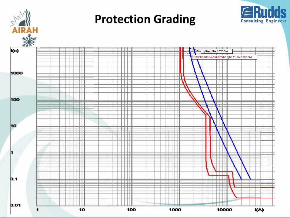
Protection Grading
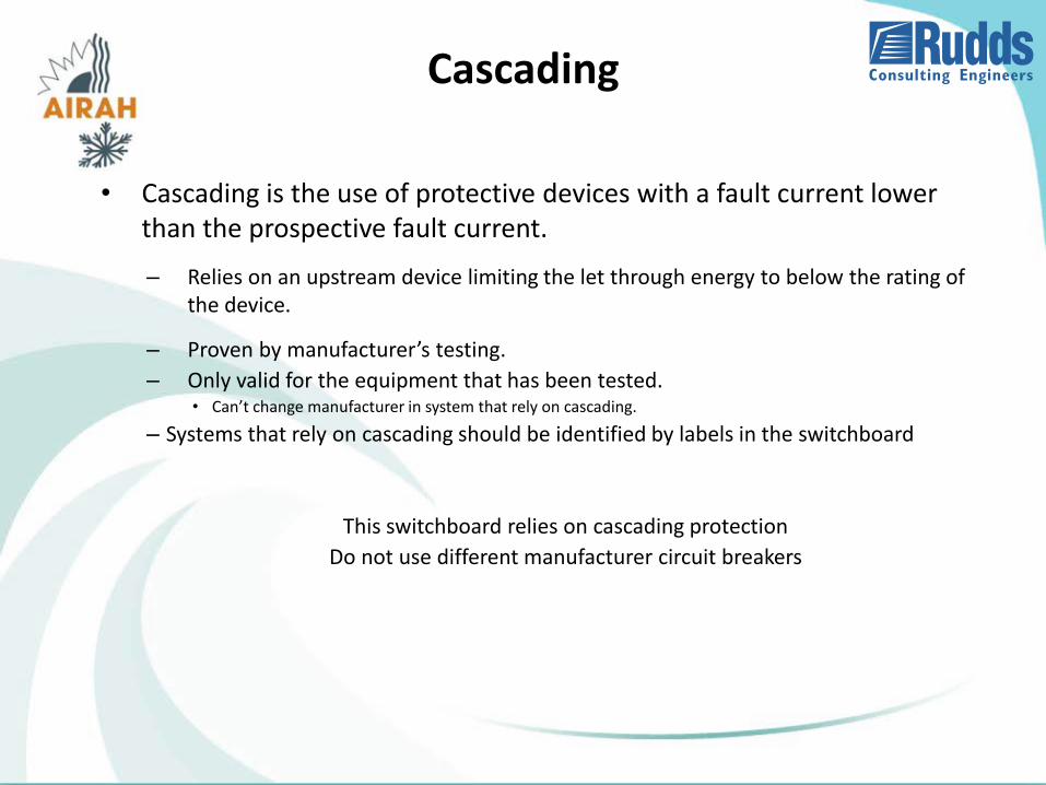
Cascading
• Cascading is the use of protective devices with a fault current lower than the prospective fault current.
– Relies on an upstream device limiting the let through energy to below the rating of the device.
– Proven by manufacturer’s testing.
– Only valid for the equipment that has been tested.• Can’t change manufacturer in system that rely on cascading.
– Systems that rely on cascading should be identified by labels in the switchboard
This switchboard relies on cascading protection
Do not use different manufacturer circuit breakers
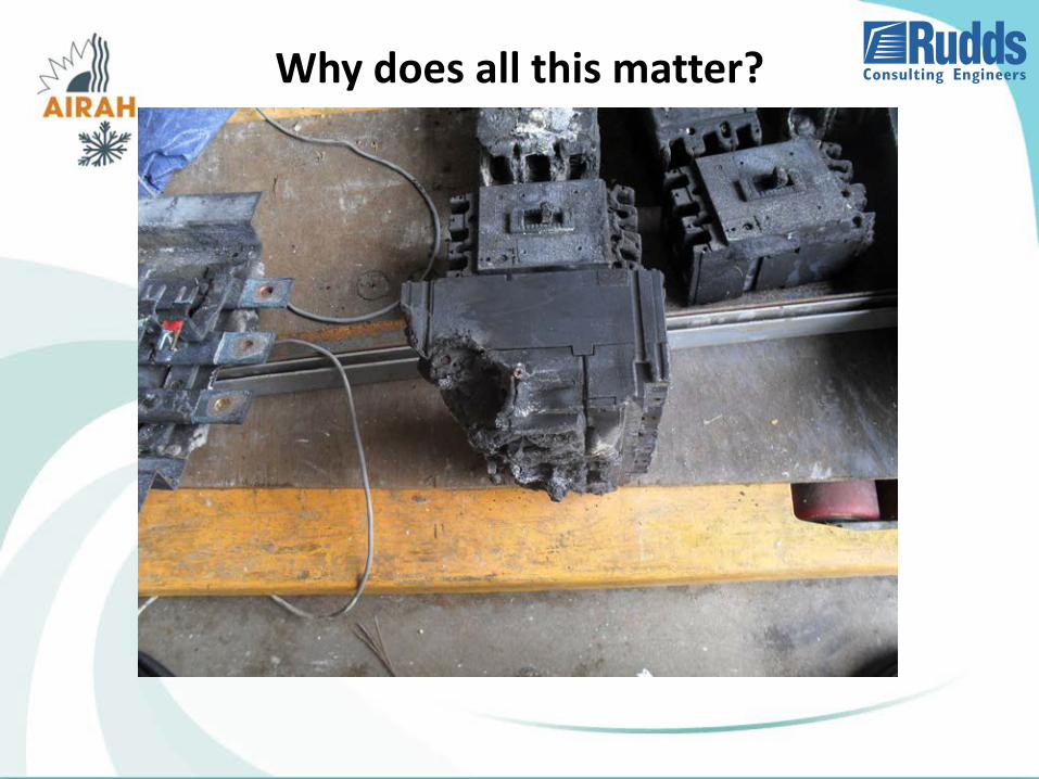
Why does all this matter?
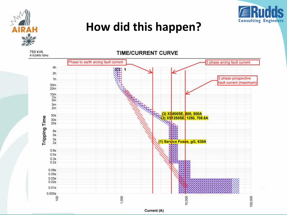
How did this happen?
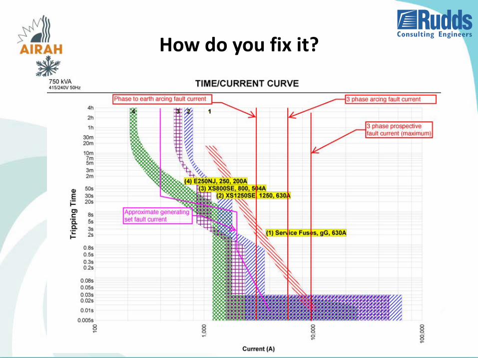
How do you fix it?
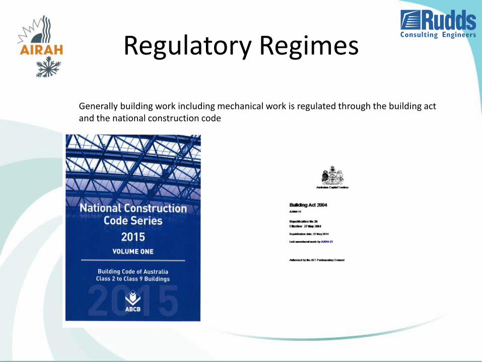
Regulatory Regimes
Generally building work including mechanical work is regulated through the building act and the national construction code
Electrical work is regulated via a different and independent system through the occupations licencing act and the electrical safety actthe occupations licencing act and the electrical safety actthe occupations licencing act and the electrical safety act

The construction occupations act covers ten occupations
Asbestos Assessor
Builder
Building Assessor
Building Surveyor
Drainer
Electrician
Gasfitter
Plumber
Plumbing plan certifier
Works Assessor
ELECTRICAL SAFETY ACT
Calls up AS/NZS 3000 as the primary technical compliance standard.Requires electrical work to be carried out by someone who is licensed
Punitive in application and defines offences if conditions are not met.The key features are
• Electrical work must be inspected tested and passed by an inspector before connection to the electricity network
• Electrical work must be carried out by licensed person• Electrical work must be registered and notified to the registrar. (Access Canberra)• Electrical work must be registered and as a result can be inspected• Penalties apply for unsafe work• Unsafe work can be disconnected.
The act also defines roles and powers of inspectors, rectification of unsafe installations and covers electrical equipment approvals
AS/NZS 3000-2007
Importantly the electrical safety act calls up
AS/NZS3000-2007 as the primary standard for electrical work
Unlike the National Construction Code that is a performance based code,
AS/NZS3000-2007 is a prescriptive set of rules designed for application by electricians and electrical contractors.
WHY IS THIS IMPORTANT
Electrical engineers and designers have no role whatsoever in the electrical approval process
Regardless of an engineering design the electrical contractor is legally responsible for the electrical safety and compliance of electrical installations
Electrical inspection in the act is very diligent
The prescriptive nature of AS/NZS 3000-2007 means that electrical designs need to be fully compatible with the standard. This raises potential for:
• Rejection of final installation by the inspector
• Delay in connection of supply
• Contract variations in order to achieve compliance.
SAFETY SERVICESEMERGENCY SYSTEMS
ESSENTIAL LIFE SAFETY PLANT
An understanding of safety services is important as it can influence mechanical plant layout and design
Definitions:
AS/NZS 3000-2007 specifically uses the term SAFETY SERVICES This includes
• Fire and Smoke Control Equipment
• Fire hydrant pumps
• Fire detection and alarm systems
• Sprinkler pumps
• Air Handling systems that exhaust and control the spread of fire and smoke.
• Lifts
and
• Items nominated as “EMERGENCY EQUIPMENT” in the NCC Building Code of Australia
Just to make things interesting
AS/NZS 1668.1 uses the term “ESSENTIAL SERVICES”
Control and Isolation
• Safety Services must be arranged so that control is separate from the control of other equipment
• Circuits for Safety services must be separate from other circuits
• Failure or fault on one safety service must not result in the loss of other safety services
• Faults in the general installation must not result in the loss of supply to safety services – protection grading.
• There must be a metal barrier in the switchboard between safety services section and other sections of the switchboard
Control and Isolation
Implications• Avoid mechanical control panels that mix safety
services and non-safety services
• Leave space for separate conduits or spacing between cable reticulation.
• Be careful in the design of electrical protection (see slides on discrimination)
Wiring Systems
All wiring systems must have a WS classification in accordance with
AS/NZS 3013.
The selection of WS classification is determined by the relevant Standard
The NCC BCA typically calls up WS 52W
AS 1668.1 Appendix E describes wiring for Smoke controls
The base requirement is for 120 minutes fire rating
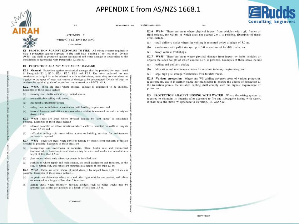
APPENDIX E from AS/NZS 1668.1
Wiring Systems AS/NZS 3013-2005
AS/NZS 3013 is a test specification that allows cabling and other systems to be tested and certified for fire rating and mechanical strength.
• The first numeral is the fire rating.
• The second numeral describes mechanical resistance to impact
• A third item W can be added to include spraying with water after the fire test.
The basic 2 hour fire rating is WS 5X
Typically WS 52 is the commonly specified cabling system.
Wiring Systems AS/NZS 3013-2005
Important things to know
Access Canberra have a very literal and strict interpretation of fire rating of submains.
Electrical contractors have to provide a dossier that supports the cable selection and the CABLE SUPPORT SYSTEM.
This dossier must include certification of the cable and support system as well as certification that the system is supported from a 2 hour fire rated
building element.
There are very few certified cable support systems on the market
In other words if it hasn’t undergone a fire test to AS/NZS 3013-2005 don’t use it.
Wiring Systems AS/NZS 3013-2005Implications
• Natspec the standard standard clauses pass the responsibility on to the
contractor.
• If you specify a cable type or document cable tray systems, you need to make
sure that it is an approved system.
• The certified systems are expensive and bulky. Therefore you need to allow
space for them in your planning.
• Existing cable systems although compliant when installed, may not meet
current Standards
• AS/NZS 3013 has been amended and re-issued over time with revised testing
and certification.
• Many existing systems that were certified in the past won’t necessarily have
certification to the current AS/NZS 3013-3005. (MIMS cables are an example)
Generators and Redundancy
ISSUES TO CONSIDER
• Types of transfer switch based on location
• Generators that back up safety services have additional
conditions.
• Brief that require no break return to mains
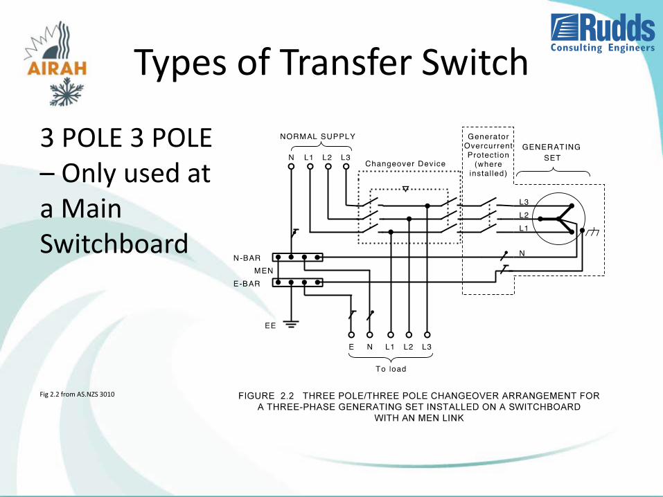
Types of Transfer Switch
3 POLE 3 POLE– Only used at a Main Switchboard
Fig 2.2 from AS.NZS 3010

Types of Transfer Switch
3 POLE 4 POLE– Used within an electrical installation away from the main Switchboard
Fig 2.8 from AS.NZS 3010
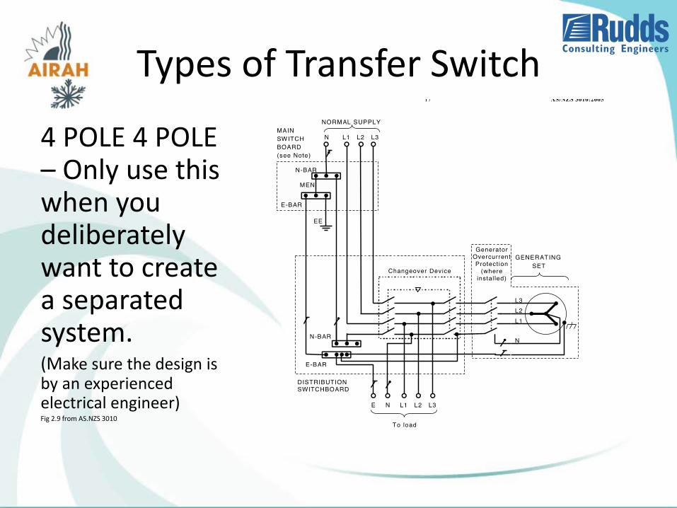
Types of Transfer Switch
4 POLE 4 POLE– Only use this when you deliberately want to create a separated system. (Make sure the design is by an experienced electrical engineer)Fig 2.9 from AS.NZS 3010
Transfer SwitchesDangers and Risks if you get it wrong
Circulating Neutral Currents
• Current can flow in the neutrals of circuits that have been isolated (safety risk)
• Currents can flow in earth cables. (Safety risk)
Incorrect neutral connection
• Fault loop can be increased to the extent that protection doesn’t trip on earth fault
Incorrect use of 4 pole 4 pole
• Loss of neutral/earth reference if transfer switch fails in open position
• Loss of neutral/earth reference during transfer (Problem with down stream UPS)
Transfer SwitchesTypes Location and Connection
A good rule is to ensure that the specification references AS/NZS 3010
Considerations for Generators that support Safety Services
THE GENERATOR ROOM MUST MEET 2 HOUR FIRE SEPARATION
• Generator room
• Supply Air and exhaust for generator cooling
• Fuel system
THE CABLING SYSTEMS FROM THE GENERATOR TO THE SAFETY SERVICES MUST ACHIEVE WS 5X MINIMUM
THE LOCATION OF THE GENERATOR CONNECTION IS LIMITED BY AS/NZS 3000-2007
• At the Main Switch Board
• At the safety services control panel
No Break Transfer
BRIEFS THAT SPECIFY NO BREAK TRANSFER INTRODUCE ADDITIONAL REQUIREMENTS
The ActewAGL service and installation rules will allow this under very strict conditions.
If the transfer takes more than 400 milliseconds the system is considered to be an embedded generator.
This requires a detailed formal submission to ActewAGL and imposes very strict control and protection requirements on the generator system.
Typically costing $60,000 in protection and controls
Short time parallel systems still require a formal submission but may not need the backup protection system.
For these briefs make sure you engage qualified and experienced designer.

Questions


![Status of Non-contact Electrical Measurementsextras.springer.com/2003/978-0-7354-0152-5/Cdr_pdfs/Indexed/782_1.Pdfstandards developed for non-contact electrical measurements [6 - 8]](https://img.pdfslide.us/doc/110x75/5ea5b5f526c98b280e0d28e3/status-of-non-contact-electrical-standards-developed-for-non-contact-electrical.jpg)