Embed Size (px)
Citation preview

22

www.schleich.com23
MotorAnalyzer 2 | All-purpose electric motor tester ..................................... 24 MotorAnalyzer 1 | All-purpose electric motor tester ..................................... 28 Product and accessory overview ..................................... 32
The MotorAnalyzer-Class Unbeatable versatility
Motor RepairElectrical Engineering Maintenance
Mot
orA
naly
zer-
Clas
sM
otor
Rep
air

24
Highlights
The MotorAnalyzer-Class
• 11testmethods• surgevoltageupto3000V• high-voltageDCupto6000V• large,verywell-readablecolordisplay• innovativehandyinputviarotarybutton• structuredmenuandpracticalfunctioningbuttons• fully-automaticfaultanalysis• automaticswitchoverbetweenthethreemotorconnectingleads• manualandautomatictests• locatingturn-to-turnfaults• adjustingtheneutralzone• rotarybuttonforaquicktestmethodselection• integratedresultstorageforasubsequenttransfervia USB-interface• storingandprintingoftestresultsviaPrintCom• networkorbatteryoperation• worldwidevoltagesupply110V…250V/47…63Hz• lowweight• all-purposesolidcaseincludingallmeasuringleads“onboard”
The all-purpose MotorAnalyzer 2 serves for checking electric motors and winding goods. It combines eleven different test methods within a user-friendly and mobile tester. The combination of test methods, its extremely compact design, as well as the battery operation turn the MotorAnalyzer into an ideal tool for the on-site operation, especially in diffi cult installation positions.
For checking a 3-phase motor the three winding connections and the motor’s cabinet are connected to the tester. This should be performed in four-wire technology for a high-precise resistance measuring. Afterwards the MotorAnalyzer analyzes the motor fully-automatically via surge-voltage, resistance, and inductivity test. For this the MotorAnalyzer automatically switches the different test methods to the four measuring points one after another via its internal relay matrix. After this the motor is also tested automatically with a high-voltage test in order to evaluate the motor’s quality quickly and clearly.
In addition to the motor test the MotorAnalyzer also assists in adjusting the brush holder at DC motors as well as in locating turn-to-turn faults.
The very compact case is sturdy and waterproof. On the right-hand side of the operating element there is a storage space. All measuring leads and test probes are stored here. Thus the operator can always access the necessary components during the measuring. For an optimum operator guidance the LEDs indicate the measuring leads that are activated for the respective measuring.
USB
PC
I/O
MotorAnalyzer 2 | All-purpose electric motor tester

www.schleich.com25
PrintCom RESULTS
Mot
orA
naly
zer-
Clas
sM
otor
Rep
air
inspection test of a pump motor
Scanning and storing test results in Excel®
All control elements and connections are clearly arranged Large and high-contrast color display
Printing test results
PrintCom – fi ling and printing test results in Excel®
With PrintCom you can protocol and store your test results quickly and comfortably:• scanningtestresults• storingtestresultsinExcel®
• printingtestresults
For detailed information please look at page 68

26
The MotorAnalyzer-Class
MotorAnalyzer 2 | 11 test methods in one tester
For the automatic test of a three-phase current motor the three winding connections and the motor cabinet have to be connected to the tester. The MotorAnalyzer analyzes the motor fully automatically via the resistance, inductivity, the surge-voltage, and the high-voltage test. It checks whether the winding is ohmically or inductively symmetrical. If the deviations of the three phases among each other are too large the motor is defect. In addition the electric strength within the winding and to the motor’s cabinet is tested.
For the inductive winding check the MotorAnalyzer generates surge pulses up to 3000V that can be continuously adjusted. The patented automatic surge voltage comparison of the windings among each other or to a reference test object provides precise statements regarding the winding’s symmetry. The MotorAnalyzer detects any nonsymmetries automatically.
The resistance test is performed with very high precision in four-wire technology. The symmetry evaluation of the three winding resistances or the comparison to a preset value is performed automatically. A temperature compensation converts the copper resistance to 20°Celsius if required. For the ambient temperature measuring an ambient temperature sensor has to be connected to the Motor Analyzer.
The inductivity test is also performed in four-wire technology like the resistance test. The symmetry evaluation of the three winding inductivities or the comparison to a preset value is performed automatically.
For the high-voltage test the MotorAnalyzer generates a very stable test voltage from 50 to 6000V DC. At the automatic test the voltage is max. 3000V and at the manual test it is max. 6000V due to the test probes. The voltage can be set manually at the rotary button. Alternatively it can also be set automatically to a programmable value. A step voltage measuring is possible as well.
For the insulation resistance test the MotorAnalyzer generates a very stable test voltage from 50 to 6000V DC. At the automatic test the voltage is max. 3000V and at the manual test it is max. 6000V due to the test probes. The voltage can be set manually at the rotary button. Alternatively it can also be set automatically to a programmable value. A step voltage measuring is possible as well.
1 Automatic analysis
3 Resistance test
4 Inductivity test
2 Surge test up to 3000V
5 High-voltage test DC
6 Insulation resistance test
www.schleich.com27
Mot
orA
naly
zer-
Clas
sM
otor
Rep
air
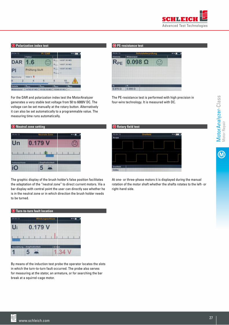
For the DAR and polarization index test the MotorAnalyzer generates a very stable test voltage from 50 to 6000V DC. The voltage can be set manually at the rotary button. Alternatively it can also be set automatically to a programmable value. The measuring time runs automatically.
The graphic display of the brush holder’s false position facilitates the adaptation of the “neutral zone” to direct current motors. Via a bar display with central point the user can directly see whether he is in the neutral zone or in which direction the brush holder needs to be turned.
By means of the induction test probe the operator locates the slots in which the turn-to-turn fault occurred. The probe also serves for measuring at the stator, an armature, or for searching the bar break at a squirrel-cage motor.
The PE-resistance test is performed with high precision in four-wire technology. It is measured with DC.
At one- or three-phase motors it is displayed during the manual rotation of the motor shaft whether the shafts rotates to the left- or right-hand side.
8 Neutral zone setting
9 Turn-to-turn fault location
7 Polarization index test 10 PE-resistance test
11 Rotary fi eld test

28
Highlights
MotorAnalyzer 1 | All-purpose electric motor tester
The MotorAnalyzer-Class
• tentestmethods• high-voltageupto4KV• fullyautomaticfaultanalysis• automaticswitchoverbetweenthethreemotorconnectingleads• manualandautomatictests• locationofturn-to-turn-faults• mainsand/orbatteryoperation• lowweight• canalsobesuppliedinasturdymeasuringbox• rotarybuttonforaquicktestmethodselection• integratedresultstorageforalatertransferviaRS232-or USB-interface• storingandprintingoftestresultsviaPrintCom
The MotorAnalyzer is an all-purpose tester for testing electric mo-tors and winding products. It combines ten different test methods in a user-friendly, mobile tester. The combination of test methods, its very compact design, as well as the option of a battery opera-tion turn the MotorAnalyzer into an ideal tool for the at-site use – especially at diffi cult installation positions.
For checking the three-phase current motor the three winding con-nections as well as the motor cabinet are connected to the tester. Afterwards the MotorAnalyzer analyzes the motor automatically via the surge and resistance test. After this a high-voltage test is also performed at the motor in order to evaluate the motor’s quality quickly and clearly.
Search of a turn-to-turn fault at a stator with induction test probe
RS232
USB
PC
I/O

www.schleich.com29
PrintCom RESULTS
PrintCom – fi ling and printing test results in Excel®
With PrintCom you can protocol and store your test results quickly and comfortably:• scanningtestresults• storingtestresultsinExcel®
• printingtestresults
Motor test
Scanning and storing test results in Excel®
MotorAnalyzer 1 with stator size 350
Printing test results
MotorAnalyzer 1-portable
For detailed information please look at page 68
Mot
orA
naly
zer-
Clas
sM
otor
Rep
air

30
1
2
3
4
1
7
9
10
8
3
4
5
6
2
Auto. Test
surge test
Widerstandresistance
Hochspannunghigh-voltage
PolarisationPI/DAR
Isolationswiderstandinsulation resistance
SchutzleiterwiderstandPE-resistance
Neutrale Zoneneutral zone
Drehfeldrichtungrotary field direction
Feldstärkenmessungfield strength measuring
Windungsschlussturn-to-turn fault
Setup
MotorAnalyzer 1 | 10 test methods in one tester
The MotorAnalyzer-Class
For the automatic test of a three-phase current motor the three winding connections and the motor cabinet are connected to the tester. Afterwards the MotorAnalyzer analyzes the motor fully automatically via the surge and resistance test. It checks whether the winding is ohmically or inductively symmetrical. If the deviations of the three phases among each other are too large the motor is defect.
For the inductive winding check the MotorAnalyzer generates surge voltages with a low level. The patented automatic surge voltage comparison of the windings among each other or to a reference test object provides precise statements regarding the winding’s symmetry. The MotorAnalyzer detects any nonsymmetries automatically.
The resistance test is performed with high precision in four-wire technology. The symmetry evaluation of the three winding resistances or the comparison to a preset value is performed automatically. A temperature compensation converts the copper resistance to 20°Celsius if required.
For the high-voltage test the MotorAnalyzer generates a very stable test voltage from 50 to 4000V DC. The voltage can be set manually at the rotary button. Alternatively it can also be set automatically to a programmable value.
1 Automatic analysis 3 Resistance test
4 High-voltage test DC
2 Surge test

www.schleich.com31
5
7
8
9
10
6
6
6
For the DAR and polarization index test the MotorAnalyzer generates a very stable test voltage from 50 to 4000V DC. The voltage can be set manually at the rotary button. Alternatively it can also be set automatically to a programmable value.
The PE-resistance test is performed with high precision in four-wire technology. It is measured with DC.
The graphic display of the brush holder’s false position facilitates the adaptation of the “neutral zone” to direct current motors. With the MotorAnalyzer it can thus be adjusted in a very user-friendly way. Via a bar display with central point the user can directly see whether he is in the neutral zone or in which direction the brush rocker needs to be turned.
At one- or three-phase motors it is displayed during the manual rotation of the motor shaft whether the shafts rotates to the left- or right-hand side.
By means of the induction test probe the slots at the stator or arma-ture are located in which the turn-to-turn fault occurred. The probe also serves for searching the bar break at a squirrel-cage motor.
For the insulation resistance test the MotorAnalyzer generates a very stable test voltage from 50 to 4000V DC. The voltage can be set manually at the rotary button. Alternatively it can also be set automatically to a programmable value. A step voltage measuring is also possible.
5 Polarization index test 8 Neutral zone setting
9 Rotary fi eld test
6 Insulation resistance test
7 PE-resistance test
10 Turn-to-turn fault locationM
otor
Ana
lyze
r-Cl
ass
Mot
or R
epai
r

32
MotorAnalyzer 1 and 2 | Product and accessory overview
The MotorAnalyzer-Class
1mΩ…500KΩfour-wire measuring
low-voltage, surge voltage & autom. analysis
fault locating of the turn-to-turn fault
0…100GΩ
Model art. no.
MotorAnalyzer 1 403101 1 12V 2 0…4KV 3 0…4KV DC 3 0…4KV DC 4 5 7 2 MotorAnalyzer 1 portable 403141 1 12V 2 0…4KV 3 0…4KV DC 3 0…4KV DC 4 5 7 2 MotorAnalyzer 2 403167 1 3000V 2 0…6KV 3 0…6KV DC 3 0…6KV DC 4 5 6 7 2
Test probes | measuring leads
4-wire measuring tips for armatures 4000395
4-wire Kelvin tongs set 40001100 4-wire Kelvin tongs small 4007209
4-wire Kelvin tongs medium 4007212
4-wire Kelvin tongs large 4007168
temperature sensor for the 403109
ambient temperature compensation turn-to-turn fault test probe 9mm 403106 turn-to-turn fault test probe 19mm 403107
turn-to-turn fault armature test probe 403123
Giga-Ohm measuring lead 403110
neutral zone measuring lead 403102
rotary fi eld test probe for stator 403103
rotary fi eld test probe for motor 403112
Accessories
foot switch 4010611start buttons for test probe 403111transport box for MA 1 403124Netbook-holder for MA1-portable 403149PrintCom PC-software 401871
MotorAnalyzer 1 MotorAnalyzer 1 portable MotorAnalyzer 2
For accessories please look at page 66
Ω
resistance surge voltage
KVmAGΩ
high voltageDC
KVGΩ
insulation resistance
turn-to-turnfaults
H
inductivity

www.schleich.com33
0…4000V DC comparison assistance for the neutral zone at DC-motors
measuring at stator and motor
1mΩ…1Ωfour-wire measuring
automatic test method switchover
clamps: U-V-W-body high-voltage
measuring lead with alligator clamps
measuring lead with test tips for the high-voltage
battery operation
Model art. no.
MotorAnalyzer 1 403101 1 12V 2 0…4KV 3 0…4KV DC 3 0…4KV DC 4 5 7 2 MotorAnalyzer 1 portable 403141 1 12V 2 0…4KV 3 0…4KV DC 3 0…4KV DC 4 5 7 2 MotorAnalyzer 2 403167 1 3000V 2 0…6KV 3 0…6KV DC 3 0…6KV DC 4 5 6 7 2
Test probes | measuring leads
4-wire measuring tips for armatures 4000395
4-wire Kelvin tongs set 40001100 4-wire Kelvin tongs small 4007209
4-wire Kelvin tongs medium 4007212
4-wire Kelvin tongs large 4007168
temperature sensor for the 403109
ambient temperature compensation turn-to-turn fault test probe 9mm 403106 turn-to-turn fault test probe 19mm 403107
turn-to-turn fault armature test probe 403123
Giga-Ohm measuring lead 403110
neutral zone measuring lead 403102
rotary fi eld test probe for stator 403103
rotary fi eld test probe for motor 403112
Accessories
foot switch 4010611start buttons for test probe 403111transport box for MA 1 403124Netbook-holder for MA1-portable 403149PrintCom PC-software 401871
included in the delivery extent
1 For increasing the measuring accuracy at resistances below 1Ω it is recommended to use four-wire Kelvin tongs in addition.2 For locating the turn-to-turn fault an additional probe is required.3 In order to measure insulation resistances above 100Ω more precisely an additional GigaOhm-measuring lead is recommended.4 For connecting the DC-motor an additional measuring lead is required. 5 For measuring the sense of rotation one additional probe is required for the stator measuring and one additional measuring lead for the motor measuring is required. 6 Switchover automatically up to 3KV. High-voltage test up to 6KV via separate test tips.
measuring probes | measuring leads that need to be ordered in addition not available
four-wire measuring tips four-wire Kelvin tongs turn-to-turn fault test probe Netbook holder
Mot
orA
naly
zer-
Clas
sM
otor
Rep
air
neutral zonepolarization
mΩ
PE resistancesense of rotation matrix
1 .......... X
switch-overtest methods

66

www.schleich.com67
PrintCom Software .............................................................. 68 Lead Contactings ................................................................ 70 Test Pistols, Test Probes, Safety Accessories ................ 72 Rolling Tables ...................................................................... 74 Black Boxes ......................................................................... 76
Software & Accessories
Motor RepairElectrical EngineeringMaintenance

68
Highlights
PrintCom RESULTS
RS232
Ethernet
USB
PrintCom | Software for MotorAnalyzer, GLP1 & GLP2
Software & Accessories
• importingtestresultsduringthetestandfromthetester’s intermediate storage• storageoftestresultsintheExcel® format during the production• printoftestresultsinExcel® via protocol samples• severalready-madeprotocolsamplesincludedinthe delivery extent• freelyconfigurableExcel® protocol samples to print test results• differentstoragemodes(singleorcollectionresults)• OpenOffice®-/MS Excel® compatible software• Windows7® compliant
Archive and print test results in Excel®
PrintCom – the quickest and most comfortable way of protocolling and storing test results of MotorAnalyzer, GLP1- and GLP2-high-voltage testers.
Importing
The software lists imported test results well-arranged on your computer screen.
Storing
The test results are user-friendly stored in the Excel® format. The basis are Excel® protocol samples preconfi gured by us.
PrintCom offers you to adapt the protocol to you requirements by adding additional information or by means of an individual protocol layout, for example with your logo. In the delivery extent you will already fi nd a large variety of easily adaptable samples. Of course, you can also create completely new protocols.
Printing
Owing to the integration of the test results in an Excel® fi le you are able to print your test results directly. Thus you can impressively document the tested quality to your customer.

www.schleich.com69
PC
PC
Ethernet
Server
RS232 / USB
RS232 / USB
Softw
are
& A
cces
sorie
sM
otor
Rep
air
Connecting versions
Test Protocol
PrintCom with MotorAnalyzer

70
Highlights A typical task is the contacting of stripped line ends because test objects are often only equipped with line ends without a plug connection.
For contacting free line ends we can provide a wide range of clamp devices, for example for the application of stators’ winding connections. They can be equipped in two- as well as four-wire-technology.
When low resistances are to be exactly measured Kelvin clamps are used for the four-wire-measuring. The four-wire-technology compensates the transition resistances within the clamping points.
Our Kelvin clamps’ special design guarantees high contact reliability, solid clamping, and a low wear and tear in the rough testing operation. Less exacting contactings are operated with our multi-purpose clamping levers.
The contactings can be supplied as loose single contacting or integrated within a clamp block. The clamp blocks can either be assembled in a fi xed position within the test cover or can be moved fl exibly within the testing space to always have the optimum position for being clamped to the lines.
• variousstandardcontactings• mechanicalsolidandpersistentdesign• four-wirecontactings–Kelvinclamps• customizedsolutionsbasedonourstandardsolutions• fastexchangeofconsumables
Software & Accessories
Lead Contactings

www.schleich.com71
6-times four-wire contacting guide and 4-times clamping lever block
Kelvin clamps in small-, medium-, and large-sized design
Kelvin contacting in one test cage with prism
8-times Kelvin clamps block
11-times clamping lever block
clamp block in modular design clamp block in modular design
Examples for Kelvin clamps, clamping levers, and modular contact blocks
Softw
are
& A
cces
sorie
sM
otor
Rep
air

72
Test Pistols | Test Probes | Safety Accessories
Software & Accessories
high-voltage test pistol with start through mechanical press button
High-voltage
Safety pistols are required for a safe manual high-voltage test. Depending on the test voltage level there are different models.
To achieve a particular high usability we provide test pistols with an integrated start button. Here the high-voltage test only starts after activating the button.
high-voltage test pistol without start button
high-voltage test pistol with start button
high-voltage test pistol up to 8KV AC/10KV DC
high-voltage test pistol up to 12KV AC/15KV DC
adaptor between test object and test pistol
high-voltage connection lead
high-voltage test probe up to 1500V safety current limited

www.schleich.com73
warning or result light, horizontal warning or result light, vertical
Warning- result lights
Warning lights show whether the test object is under voltage or voltage-free.
Result lights show the total test result of the test process. Customized special displays, which can also be controlled by the tester, are also within our product range.
safety barrier with warning message
barrier post with warning light and emergency stop
two-hand start support with warning light and emergency stop
Safety
Due to safety reasons a two-hand start is used at the high-voltage test without protection cover and safety test pistols. When operating test stations the corresponding standards have to be considered.
two-hand start
Softw
are
& A
cces
sorie
sM
otor
Rep
air

74
Highlights
Rolling Tables
Software & Accessories
Rolling tables facilitate the transport of testers that can also be combined with a test cover between the test objects. A high level usability is achieved by the large, high-resistant and lockable rubber guide rollers as well as an optional push handle at the table’s front.
The rolling tables can additionally be equipped with self-closing drawer runners, in which e.g. adaptors, tools, or documentations can be stored.
• soliddesignmadeofaluminumprofiles• continuouslyheightadjustabletableplatesandbottoms• horizontalordiagonaltableplatedesigns• diagonaltableplatewithhorizontalfronte.g.todeposita keyboard• continuouslyheightadjustabledrawerswithfullextension• continuouslyheightadjustableholderfortestprobe• continuouslyheightadjustablewindingsformeasuringleads• integratedLED-warninglightinthesiderails• deliveryofassembled,directlyusablerollingtables• rollingtablesandcarriagesofthecompanyhera
rolling table with horizontal work plate and push handle
rolling table with horizontal work plate, push handle and a LED warning light integrated in the bars

www.schleich.com75
rolling table with diagonal work plate and drawer element
rolling table with diagonal work plate and integrated high-voltage test
rolling table with diagonal work plate, drawer element and cable holders
rolling table with integrated test cover, push handle, LED-warning light in the bars and holders for cables, test pistols, and test probes
rolling table with integrated test cover, drawer element and cable holders
Softw
are
& A
cces
sorie
sM
otor
Rep
air

76
Black Boxes
Software & Accessories
Black Boxes
For a regular daily check of your tester a black box is used that is connected to the tester. It is tested whether the emerging measuring values correspond to the values in the black box. If this is not the case the tester is locked. The tester can only be used again when a black box test with a proper result is performed. As we only supply digital evaluating testers this test is normally not performed with a “pass-fail-black box”. We only use one single black box and evaluate the emerging measuring values within tight tolerance limits.
Each black box consists of one connection possibility to the tester and one or several resistors and/or inductances. They can either be confi gured for one test method or for a combination of several test methods.
Each black box is delivered with the information on the resistance values and a calibration certifi cate so that the operator can set the tests properly.
Calibration resistors
For the calibration of testers precise calibration resistors are required as well. They make sure that certain test currents fl ow at different test methods and voltages.
The calibration resistors have a high precision as well as a high temperature and long-term stability. In order to conduct the heat that occurs at high currents or long measurings, reliably, we supply all calibration resistors for high test currents in special heat sink enclosures. In addition to these characteristics the resistors are designed low capacitively and low inductively.
All resistors for high test currents and low test voltages are designed in four-wire-technology.
All resistors are supplied with the information on the resistance values in the calibration certifi cate so that the corresponding conversions of the measuring values considering the resistance value are possible.
black box for PE
back box HV for test pistols
calibration resistor in four-wire-technology
calibration resistor high-voltage proof
high-current calibration resistor in four-wire-technology
black box for PE | IR | HV


![Untitled-2 [] · Romance Pink Avadable in Ramco PRODUCTS . An Clin Angelina Available in 5 ml ... PANTHER PANTHER PANTHER PANTHER Black Panther Available in 100 Ramco](https://img.pdfslide.us/doc/110x75/5b5319867f8b9a0d398b631e/untitled-2-romance-pink-avadable-in-ramco-products-an-clin-angelina-available.jpg)