Embed Size (px)
Citation preview
8/3/2019 Electrical Engineer Pupilage Training
http://slidepdf.com/reader/full/electrical-engineer-pupilage-training 1/26
NATIONAL POWER AUTHORITY
REPORT ON PUPILAGE TRAINING AT THE
GENERATION DEPARTMENT-KINGTOM POWER
STATION FROM 1ST SEPTEMBER TO 31ST DECEMBER
2010
AS PART FULFILMENT FOR THE CONFIRMATION TO
ENGINEER
SUBMITTED TO: GENERATION DEPARTMENT-
KINGTOM
PREPARED AND SUBMITTED BY: MOMODU MANSARAY
8/3/2019 Electrical Engineer Pupilage Training
http://slidepdf.com/reader/full/electrical-engineer-pupilage-training 2/26
ELECTRICAL ENGINEER (PUPIL)
JAN.2011
BACKGROUND:
Generation Department:
The Generation Department is one of the key departments in the overall operations
of the National Power Authority. This Department has the responsibility of
Generating Electrical power to the entire capital city of Freetown and its immediate
environs .The Department is housed at the Kingtom power station.
The Kingtom Power Station:
The kingtom power station has served as the main generating point for electrical
power Generation to the Capital city of Freetown and its immediate environs. This
was achieved through the use of thermal generators since 1965 when it was official
opened to take over this function from the older power stations of Blackhall Road
and Falcon Bridge.
Presently Kingtom power station is on standby i.e. none of the thermal generators
are running. Unless for the two Thermal Generators rated 5 MW each which were
installed by the Japanese International cooperation agency (JICA) Known as Niigata
Machines .These generators are only run when there is dare need. E.g. drop in the
output capacity of the other sources of generation.
Electrical power generation is from the following sources other than these Niigata
machines housed at the kingtom power station:-
Independent power providers (IPP)
1 Global Trading Group (GTG) at Kingtom
2 Bumbuna Hydro Electric Corporation
8/3/2019 Electrical Engineer Pupilage Training
http://slidepdf.com/reader/full/electrical-engineer-pupilage-training 3/26
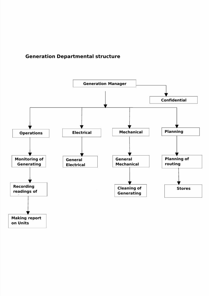
Generation Departmental structure
Generation Manager
Operations
Confidential
Electrical Mechanical
Monitoring of
Generating
Recording
readings of Stores
Planning
General
Electrical
General
Mechanical
Cleaning of
Generating
Planning of
routing
Making report
on Units
8/3/2019 Electrical Engineer Pupilage Training
http://slidepdf.com/reader/full/electrical-engineer-pupilage-training 4/26
1st -30th September
ELECTRICAL MAINTENANCE
Electrical maintenance section has the responsibility to ensure that all electrical and
electronics control and protective devices within the operations of generating
electrical energy up to the point of transmission are operative and functional.
These equipments and devices must operate to make or break contacts as and
when the situation desires for the proper operation, protection and control of the
system.
Periodic tests are carried out on instruments. E.g. protective and control devices
and also other equipments to ascertain their integrity. Some of these devices are
housed on the main control panel. Examples are;
Instantaneous earth fault relays
Instantaneous over current protection relays
Distance protection relays
Negative sequence protection relays
Directional relays
Differential relays
Over/under voltage protection relays
Neutral Displacement protection relays
Rotor earth fault
Field failure/negative phase sequence
8/3/2019 Electrical Engineer Pupilage Training
http://slidepdf.com/reader/full/electrical-engineer-pupilage-training 5/26
This section is also responsible for all electrical installations and maintenance in the
Power Station. It carries out maintenance practices based on the following
demands.
• Schedule maintenance
• Corrective maintenance
• Routine maintenance
The overall objective is to maintain satisfactory performance of all electrical
components and systems of the engines.
Some of the activities of this section include:
• Install, test and commission all electrical control panels, switchgears and
other auxiliaries using the manufacturers’ diagrams
• Inspect/check panels for cable defects, burnt contactors, blown fuses and
repair/replace the affected accessory/equipment
• Install/inspect auxiliary pumps/motors, repair burnt motor windings and
address damage to pumps
• Check the automatic voltage regulator performance
• Inspect the alternator periodically with a view to carry out maintenance if the
engine had been out of operation for a long period
• Inspect/check exciter against voltage effect, resistance/temperature, test
alternator rotor/stator windings of the engine
• Carry out fault diagnosis and resolve those related faults using diagrams
• Check/service government functionaries standby generators
• Regular inspections/servicing of the system high tension panel andswitchgears and other electrically driven equipments (cranes)
• Carry out maintenance on the lighting/power system within the PowerStation
and staff quarters
• Any other electrical work that may be assigned to the section by the
Generation Manager
8/3/2019 Electrical Engineer Pupilage Training
http://slidepdf.com/reader/full/electrical-engineer-pupilage-training 6/26
SWITCH GEAR ROOM
At the switch gear room the brand and type of switches are mainly the Yorkshire –
F6 switch gear. Their current rating is 630A and 1250A for feeder and generator
breaker and 2500A Bus-Bar rating. The other type found in the switch gear room is
the Merlin Gerlin type of fuses also rated at 630A.They are gas operated switch
gears and can be charged automatically or manually .Some are remotely operated
from the control room whilst others are manually operated down in the switch gear
room.
Though electrical power generation is now from different generating sources like
the GTG, Bumbuna and Niigata most the generated electrical power has to gothrough the 11 KV bus bar systems at the Kingtom power station. This is achieved
by means of synchronizations. I.e. voltage, Phase angle and frequency must match.
Also there are other supply points from the Bumbuna which does not pass through
the 11KV system arrangement at the kingtom power station. One such supply goes
straight from the 161KV transformer sited at the Bumbuna Freetown Site at
Kingtom to Congo Cross 2 through the JICA newly constructed overhead lines and
the other feed is known as Mandalay2
Though the following machines were not operational,
Sulzer 4&5;
Mirless 1 & 2;
Mitsubishi and
Caterpillars
Their alternator systems and the method of excitation is hereby explained below
ALTERNATOR SYSTEM
SULZER MACHINES:
Excitation by commutation- brush type alternator (magnetized by
flashing).
1. After rated speed (synchronous) is achieved, the field switch in the control
room is closed thereby closing the field breaker.
8/3/2019 Electrical Engineer Pupilage Training
http://slidepdf.com/reader/full/electrical-engineer-pupilage-training 7/26
2. The field flashing unit (time lag delay off operation) that is incorporated in the
field breaker closes to energize the excitation stator windings (creating field)
3. The excitation rotor winding produces voltage that is sent through the
commutator (Pulsating switch) that rectifies the AC voltage to pulsation DC
voltage
4. The pulsating voltage then supply the main rotor coil through the field
breaker and slip rings (+ve & -ve)
5. The energized rotating rotor (current carrying conductor) develops fluxes that
cut into the main stator winding. A voltage is produced in the main stator
winding (11kV), since the flash circuit initiate the process, when about 40% of
output voltage is produced, the flash field circuit disengage through time lag
relay and then the AVR unit comes into operation to supply the excitation
voltage (receiving supply through the AVR transformer, 11Kv/50V)
6. Part of the 11kV is passed through a step down transformer (excitation
transformer) to produce 50V A.C (maximum output) that is now sent to the
AVR while the bulk of the power is sent to the main bus bar via 1250 Amps
circuit breaker
7. The supplied AC power to the exciter stator winding is now rectified as it
induces power into the exciter rotor winding through a commutator (pulse
switch that produces a pulsating voltage (+ve and –ve). In this way a DC
power is produced and sent into field breaker and the process continues on
and on. The AVR unit continues to monitor and stabilize the output voltage.
CATERPILLAR, MIRRLEES AND MITSUBISHI:
A self-excitation, brushless with permanent magnet alternator
1. As the rotor of the alternator starts rotating with synchronous speed the PMG
automatically energize the AVR to initiate the magnetizing process
2. The breaker of the AVR then make available the correct AC voltage for
excitation process
3. An auxiliary contact of the field breaker (interlock contactor system) is
closed; further energizing the exciter main stator coils by manually closing
the field switch on the control room panel
4. The exciter rotor then produces a three phase AC voltage that goes through
six diodes for rectification (three +ve and three –ve)
8/3/2019 Electrical Engineer Pupilage Training
http://slidepdf.com/reader/full/electrical-engineer-pupilage-training 8/26
5. This rotating diode then rectifies the AC voltage into DC voltage that is
conducted into the main rotor field coils along a common shaft
6. The energized rotating rotor (current carrying conductor) develops fluxes that
cut into the main stator winding
7. A voltage (about 11kV) is produced in the main stator winding
8. Part of the 11kV is passed through a step down transformer (excitation
transformer) to produce 50V ac (maximum output) that is sent to the AVR
while the bulk of the power is sent to the main bus bar. The AVR isolate the
PMG from the system when about 40% of the output voltage is produced
The supplied AC power to the AVR then continues the excitation process
endlessly. Since Mirrlees 2 output voltage is 6.6kV, an inter bus transformer
(6.6kV/11kV) is installed between the AC output and the 11kV switchgear
room
EXCITATION SYSTEM
The exciter rotor is a three-phase AC with six leads (three to a +ve plate and three
to a –ve plate) for diode connection. The diodes are connected to form a full wavebridge rectifier. These rotating diodes are mounted on an alluminium heat sink.
A varistor (non-linear resistor) is connected across to DC terminals from the rectifier
to prevent surges generated in the main field coil (winding) from damaging the
diodes. The principle is also applicable to the Caterpillar, Mirrlees 2 (brushless
alternator) and Mitsubishi engines respectively. The Sulzer engine has a
commutator (instead of rotating diode) slip ring, variable resistor (instead of
varistor)
EXPERIENCE GAINED:
During the training I participated in the following electrical maintenance work.
• installation of a new YSF6 Cubicle switch gear

8/3/2019 Electrical Engineer Pupilage Training
http://slidepdf.com/reader/full/electrical-engineer-pupilage-training 9/26
• repair work on the overhead crane in the power house
• the drain pit pump motor control system
• installation of an AVR on a 60KVA Gen. set
• refurbishment of one YSF6 cubicle switch gear
• Work and function test on the automatic transfer switch at President Lodge
after Lighting strike
1st-22nd October
MECHANICAL MAINTENANCE:
This section is responsible to work on all breakdown of machinery that is
mechanical. They either fabricate these parts by the use of the lathe machines
where necessary or put in requisition for the supply of the worn out parts to stores.
Where these parts are not available in the stores, then an order is placed with the
full knowledge of the Management of the generation department to the
Management of the authority
This section is now a shadow of it former status as the only machines which are now
operational are the Niigata machines which are very new ones and far fromdeveloping major mechanical problem as they are seldom used. Even if mechanical
faults may occurs these machines are still under the warranty period.
Maintenance methods and practices is the key to the proper functioning of this
section.
In the event of a less strategic maintenance work, skilled personnel undertake such
maintenance while highly strategic jobs require the services of expatriates or
consultants even though the bulk of the work is being carried out by local
personnel.
Basically, corrective and preventive maintenances were carried out at the Kingtom
Power Station.
Corrective maintenance
This is an unplanned maintenance as it is carried out on an emergency basis.
Corrective maintenance is subdivided into:
8/3/2019 Electrical Engineer Pupilage Training
http://slidepdf.com/reader/full/electrical-engineer-pupilage-training 10/26
• Breakdown maintenance and
• Plant defect corrective maintenance
Preventive maintenance
This is a scheduled and planned maintenance.
Preventive maintenance is also subdivided into:
• Planned maintenance
• Routine maintenance
Breakdown maintenance is carried out without proper planning and hence a
predetermined downtime of the plant could not be determined. The unavailability of
readily needed spare parts to bring the plant into operation at the shortest possible
time could be a major constraint.
Plant defect corrective maintenance is carried out on the plant to arrest defects that
might not sometimes necessarily lead to the shutting down of the plant as it does
not have any performance reduction effect on it and pose no threat to its smooth
running. The execution of such maintenance job can be deferred to coincide with
the plant shutdown to reduce engine down time. If however the defect threatens
the smooth running of the engine, it is shut down to arrest the problem
immediately.
Planned maintenance jobs (major overhauls) are executed following a long term
planning of activities to be undertaken without the plant necessarily breaking down.
Such maintenance is guided by the recommendations of the manufacturer that
would include the necessary spares, maintenance activities, and duration for the
successful completion of the job. When necessary, the services of expatriates are
sought for which detailed report is submitted by the consulting firm at the end of
the job.
Routine maintenance practices rely on recommended set of job activities that
should be executed within a stipulated time frame set by the manufacturer. The
operational performance, the working environment and the hours run of the plantare taken into consideration and the time interval adjusted to suit the prevailing
circumstance. Samples of maintenance work order are also submitted to give a clue
on few of the maintenance activities carried out under this type of maintenance.
With this type of maintenance practice in place, breakdowns are minimized, engine
lifespan prolonged and operations cost reduced.
8/3/2019 Electrical Engineer Pupilage Training
http://slidepdf.com/reader/full/electrical-engineer-pupilage-training 11/26
The Central workshop
The central workshop is an auxiliary arm of the Mechanical Maintenance section and
is headed by a Workshop Superintendent taking directives from the Senior
Maintenance Engineer.
Some of the activities carried out by the Mechanical Maintenance section include:
•• Inspecting and servicing of turbochargers, cylinder heads, injectors, pistons
•• Major overhauling of engines
•• Inspecting of water and fuel supply lines for leakages and carry out the
necessary repairs
•• Checking the status of the various pumps and motors
••
Inspecting and servicing of oil coolers
•• Replacing of defective fuel valves, relief valves and filters etc. etc.
During the period of my training there was not much going on at the kingtom power
station in terms of mechanical maintenance work as the station is on standby and
hence the mechanical maintenance section is therefore engaged in servicing out of
station machines sited at the following places:
• State Lodge
• Parliament
• VP lodge
• VP Office
• State House
This has now lead to massive transfer of staff from this section to other area within
the Authority
This section mostly works in conjunction with the electrical maintenance section for
all provincial stations that have Generators run by NPA.
EXPERIENCE GAINED:
8/3/2019 Electrical Engineer Pupilage Training
http://slidepdf.com/reader/full/electrical-engineer-pupilage-training 12/26
As the maintenance work within the power station was low key we used the
opportunity to visit all out stations to ensure that the machines were properly cared
for by the Engine attendants and electricians deployed at the site
Checks carried out before these generators at the various stations were started
include:
• Coolant level
• Lubricating Oil Level
• Radiator and Alternator fan Guards properly secured
• Fan belts tension
• Look for other leakages
Other than going out of the kingtom power station my training with the Mechanical
maintenance also included taking me on a conducted tour of the setup of the fuel
pipe lines from the fuel storage tanks for MFO (marine fuel oil) unto the service tank
for all the Generators installed in the power station including the two Sulzers and
the Mirless machines. During this tour I was shown the following equipments and
items listed below and their functions
Transfer pumps, Regulating tank, Boiler, Purifiers,
Electric Heaters, Boaster pumps, Filters,
Service tanks, Compressor, Air bottle
ENGINES CHARACTERISTICS
SULZER ENGINE
•• Two-stroke
•• In-line block (8 cylinder)
•• Low speed (150 rpm )
•• Air and water cooled: water to a greater extent and air to a lesser extent
•• Air intake by scavenging
•• Has only intake and exhaust ports
8/3/2019 Electrical Engineer Pupilage Training
http://slidepdf.com/reader/full/electrical-engineer-pupilage-training 13/26
•• Air starting
•• Designed to consume both heavy and light fuel
MITSUBISHI AND MIRRLEES ENGINES
•• Four-stroke
•• V-block (16 cylinders for Mitsubishi and 12 cylinders for Mirrlees )
•• Medium speed (750 rpm for Mitsubishi and 600 rpm for Mirrlees )
•• Only intake and exhaust valves present
•• Both air and water cooled: water to a greater extent and air to a lesser
extent. The air cooling is an added benefit from the scavenged air.
••
Air starting
•• Designed to consume both heavy and light fuel
CATERPILLAR ENGINE
•• Four-stroke
•• V-block with 16 cylinders
•• High speed (1500 rpm )
•• Electric starting ( with batteries )
•• Consume light fuel only
Working cycles
The working cycle of an engine may be four-stroke or two-stroke; and the enginemay be single-acting or double-acting. These cycles are mechanical sequences of
events for the functioning of the machine. The working cycle (induction,
compression, expansion, and exhaust) is basically the same on both two-stroke and
four-stroke engines but the individual phases take place at different times and at
different points on the engine.
Operating principle of the two stroke engine
8/3/2019 Electrical Engineer Pupilage Training
http://slidepdf.com/reader/full/electrical-engineer-pupilage-training 14/26
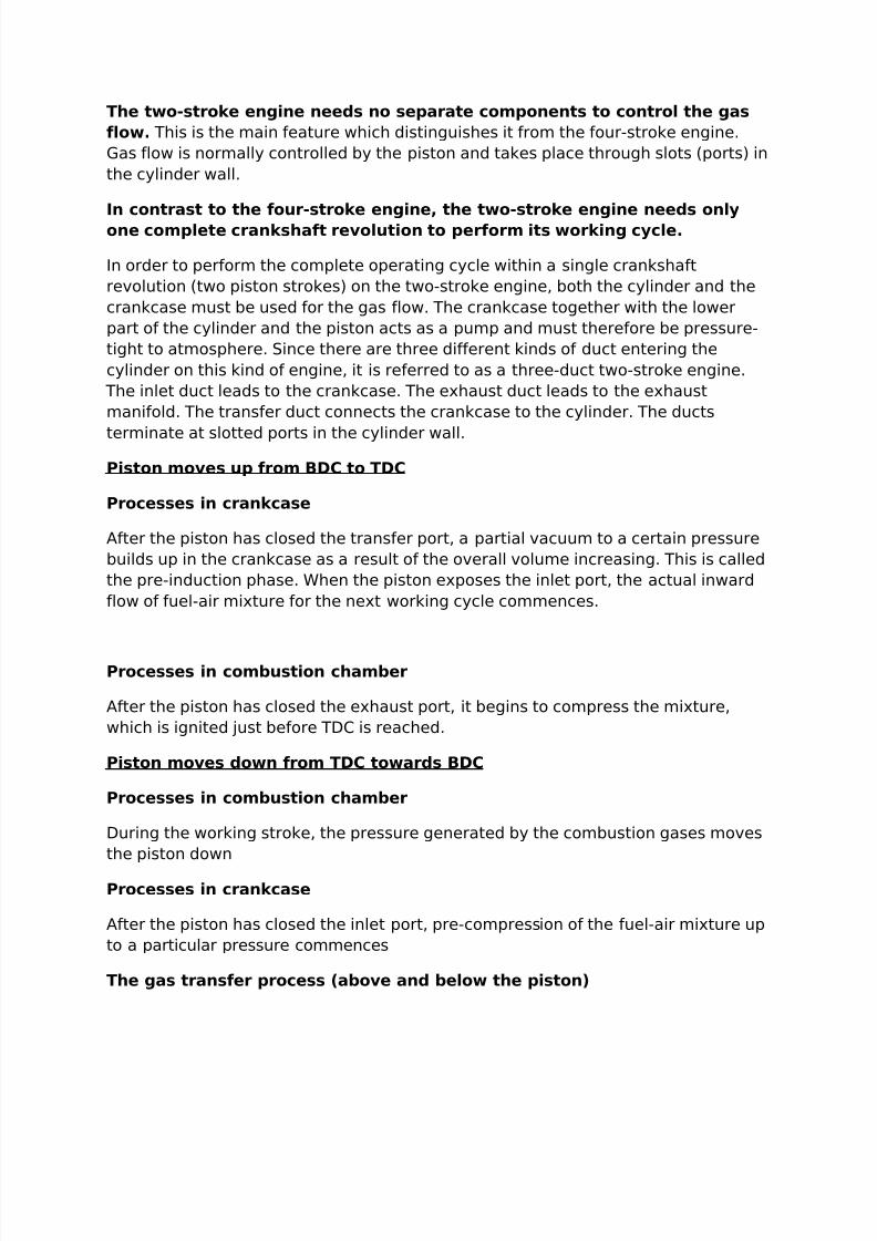
The two-stroke engine needs no separate components to control the gas
flow. This is the main feature which distinguishes it from the four-stroke engine.
Gas flow is normally controlled by the piston and takes place through slots (ports) in
the cylinder wall.
In contrast to the four-stroke engine, the two-stroke engine needs onlyone complete crankshaft revolution to perform its working cycle.
In order to perform the complete operating cycle within a single crankshaft
revolution (two piston strokes) on the two-stroke engine, both the cylinder and the
crankcase must be used for the gas flow. The crankcase together with the lower
part of the cylinder and the piston acts as a pump and must therefore be pressure-
tight to atmosphere. Since there are three different kinds of duct entering the
cylinder on this kind of engine, it is referred to as a three-duct two-stroke engine.
The inlet duct leads to the crankcase. The exhaust duct leads to the exhaust
manifold. The transfer duct connects the crankcase to the cylinder. The ducts
terminate at slotted ports in the cylinder wall.
Piston moves up from BDC to TDC
Processes in crankcase
After the piston has closed the transfer port, a partial vacuum to a certain pressure
builds up in the crankcase as a result of the overall volume increasing. This is called
the pre-induction phase. When the piston exposes the inlet port, the actual inward
flow of fuel-air mixture for the next working cycle commences.
Processes in combustion chamber
After the piston has closed the exhaust port, it begins to compress the mixture,
which is ignited just before TDC is reached.
Piston moves down from TDC towards BDC
Processes in combustion chamber
During the working stroke, the pressure generated by the combustion gases moves
the piston down
Processes in crankcase
After the piston has closed the inlet port, pre-compression of the fuel-air mixture up
to a particular pressure commences
The gas transfer process (above and below the piston)
8/3/2019 Electrical Engineer Pupilage Training
http://slidepdf.com/reader/full/electrical-engineer-pupilage-training 15/26
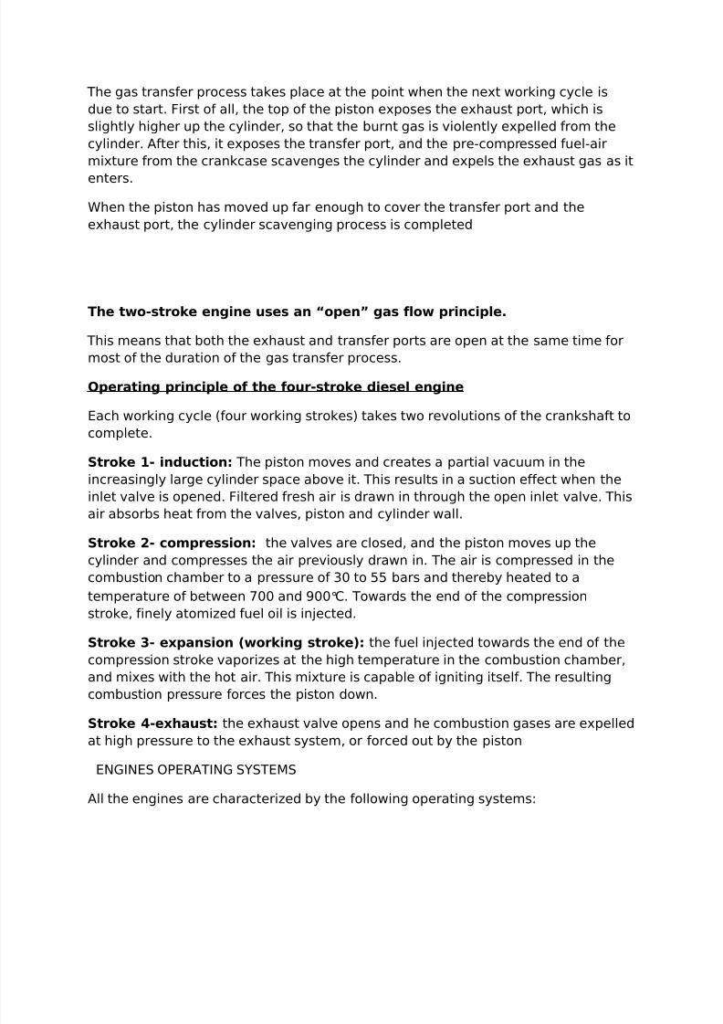
The gas transfer process takes place at the point when the next working cycle is
due to start. First of all, the top of the piston exposes the exhaust port, which is
slightly higher up the cylinder, so that the burnt gas is violently expelled from the
cylinder. After this, it exposes the transfer port, and the pre-compressed fuel-air
mixture from the crankcase scavenges the cylinder and expels the exhaust gas as it
enters.
When the piston has moved up far enough to cover the transfer port and the
exhaust port, the cylinder scavenging process is completed
The two-stroke engine uses an “open” gas flow principle.
This means that both the exhaust and transfer ports are open at the same time for
most of the duration of the gas transfer process.
Operating principle of the four-stroke diesel engine
Each working cycle (four working strokes) takes two revolutions of the crankshaft to
complete.
Stroke 1- induction: The piston moves and creates a partial vacuum in the
increasingly large cylinder space above it. This results in a suction effect when the
inlet valve is opened. Filtered fresh air is drawn in through the open inlet valve. This
air absorbs heat from the valves, piston and cylinder wall.
Stroke 2- compression: the valves are closed, and the piston moves up the
cylinder and compresses the air previously drawn in. The air is compressed in the
combustion chamber to a pressure of 30 to 55 bars and thereby heated to a
temperature of between 700 and 900°C. Towards the end of the compression
stroke, finely atomized fuel oil is injected.
Stroke 3- expansion (working stroke): the fuel injected towards the end of the
compression stroke vaporizes at the high temperature in the combustion chamber,
and mixes with the hot air. This mixture is capable of igniting itself. The resulting
combustion pressure forces the piston down.
Stroke 4-exhaust: the exhaust valve opens and he combustion gases are expelled
at high pressure to the exhaust system, or forced out by the piston
ENGINES OPERATING SYSTEMS
All the engines are characterized by the following operating systems:
8/3/2019 Electrical Engineer Pupilage Training
http://slidepdf.com/reader/full/electrical-engineer-pupilage-training 16/26
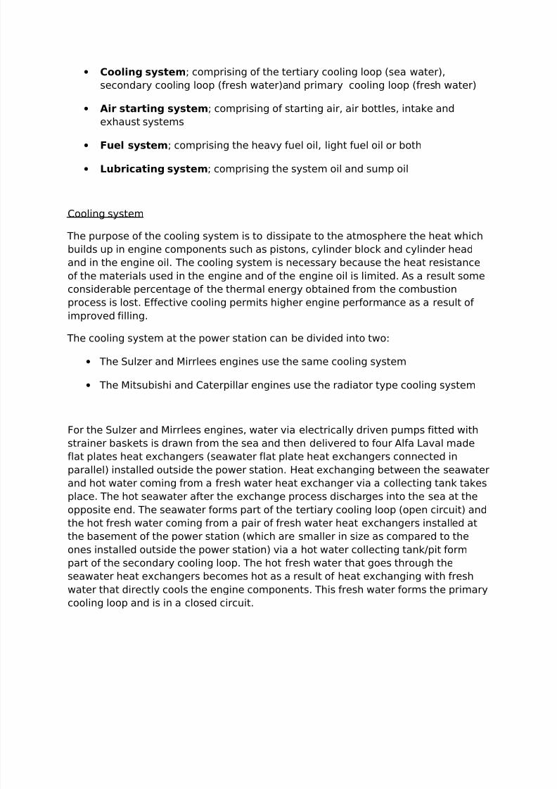
• Cooling system; comprising of the tertiary cooling loop (sea water),
secondary cooling loop (fresh water)and primary cooling loop (fresh water)
• Air starting system; comprising of starting air, air bottles, intake and
exhaust systems
• Fuel system; comprising the heavy fuel oil, light fuel oil or both
• Lubricating system; comprising the system oil and sump oil
Cooling system
The purpose of the cooling system is to dissipate to the atmosphere the heat which
builds up in engine components such as pistons, cylinder block and cylinder head
and in the engine oil. The cooling system is necessary because the heat resistance
of the materials used in the engine and of the engine oil is limited. As a result someconsiderable percentage of the thermal energy obtained from the combustion
process is lost. Effective cooling permits higher engine performance as a result of
improved filling.
The cooling system at the power station can be divided into two:
• The Sulzer and Mirrlees engines use the same cooling system
• The Mitsubishi and Caterpillar engines use the radiator type cooling system
For the Sulzer and Mirrlees engines, water via electrically driven pumps fitted with
strainer baskets is drawn from the sea and then delivered to four Alfa Laval made
flat plates heat exchangers (seawater flat plate heat exchangers connected in
parallel) installed outside the power station. Heat exchanging between the seawater
and hot water coming from a fresh water heat exchanger via a collecting tank takes
place. The hot seawater after the exchange process discharges into the sea at the
opposite end. The seawater forms part of the tertiary cooling loop (open circuit) and
the hot fresh water coming from a pair of fresh water heat exchangers installed at
the basement of the power station (which are smaller in size as compared to the
ones installed outside the power station) via a hot water collecting tank/pit formpart of the secondary cooling loop. The hot fresh water that goes through the
seawater heat exchangers becomes hot as a result of heat exchanging with fresh
water that directly cools the engine components. This fresh water forms the primary
cooling loop and is in a closed circuit.
8/3/2019 Electrical Engineer Pupilage Training
http://slidepdf.com/reader/full/electrical-engineer-pupilage-training 17/26
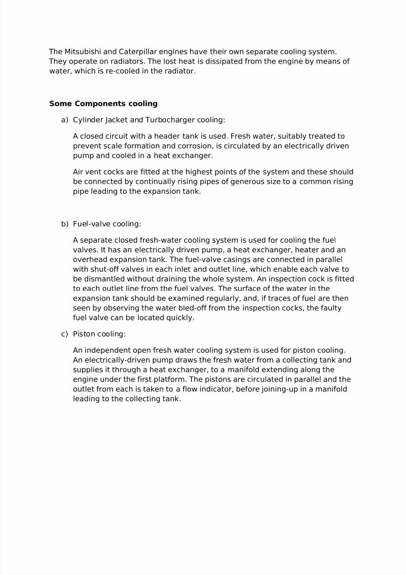
The Mitsubishi and Caterpillar engines have their own separate cooling system.
They operate on radiators. The lost heat is dissipated from the engine by means of
water, which is re-cooled in the radiator.
Some Components cooling
a) Cylinder Jacket and Turbocharger cooling:
A closed circuit with a header tank is used. Fresh water, suitably treated to
prevent scale formation and corrosion, is circulated by an electrically driven
pump and cooled in a heat exchanger.
Air vent cocks are fitted at the highest points of the system and these should
be connected by continually rising pipes of generous size to a common rising
pipe leading to the expansion tank.
b) Fuel-valve cooling:
A separate closed fresh-water cooling system is used for cooling the fuel
valves. It has an electrically driven pump, a heat exchanger, heater and an
overhead expansion tank. The fuel-valve casings are connected in parallel
with shut-off valves in each inlet and outlet line, which enable each valve to
be dismantled without draining the whole system. An inspection cock is fitted
to each outlet line from the fuel valves. The surface of the water in the
expansion tank should be examined regularly, and, if traces of fuel are thenseen by observing the water bled-off from the inspection cocks, the faulty
fuel valve can be located quickly.
c) Piston cooling:
An independent open fresh water cooling system is used for piston cooling.
An electrically-driven pump draws the fresh water from a collecting tank and
supplies it through a heat exchanger, to a manifold extending along the
engine under the first platform. The pistons are circulated in parallel and the
outlet from each is taken to a flow indicator, before joining-up in a manifold
leading to the collecting tank.
8/3/2019 Electrical Engineer Pupilage Training
http://slidepdf.com/reader/full/electrical-engineer-pupilage-training 18/26
Air starting system
Air starting is almost universal for large engines (requiring a storage tank plus a
compressor). The compressed air is piped to the storage tank. At the power station,
all the base load engines require air for starting. The air is being produced from
electrically driven air compressors and is stored in steel air bottles fitted with airpressure gauges to indicate pressure level. The engine starting air pressure is
maintained at a minimum pressure of 20 bars. The steel air bottles are however
interlinked through pipe networks to allow for flexibility in the use of a compressor
for starting various engines. Other components include the charged air cooler,
turbocharger, etc.
Fuel system
The task of the fuel supply system is to deliver to the fuel injection system with
sufficient fuel in all operating conditions. The fuel system comprises of both light
and heavy fuel oil.
The light fuel oil (diesel) is stored in the main diesel storage tank from where it is
pumped into the day tanks of the different engines via a transfer pump. From the
day tanks, delivery into the injectors is made possible with the use of a booster unit.
This unit increases the fuel pressure delivered to the injectors and consists of
duplex fuel filters which could be switched over from one filter to the other during
running for the purposes of cleaning. A change over 3-way switch is provided to
regulate the type of fuel required.
The heavy fuel oil also has its main storage tank. It is the main fuel oil that is used
by the base load engines and it is highly viscous containing impurities like water,
metallic components etc. which need to be considerably minimized to reduce the
risk of them entering the fuel line thereby creating problems to the smooth
operation of the engine. The fuel is transferred onto the regulating tank via transfer
pumps 1 and 2. The heavy fuel oil is heated partly by steam from a heat recovery
boiler and partly by electric heaters to reduce its viscosity. It then flows into the
various separators/purifiers for the removal of impurities and metallic compounds
and then sent to the various engines daily service tanks. From the service tank, it is
transferred to the booster unit; the engines are supplied with fuel through the help
of the transfer and booster pump capable of increasing fuel pressure to anacceptable pressure and circulating enough fuel more than that consumed by the
engine. The surplus fuel flows back into the day tank. Owing to the difference in
mass density and the time taken in the day tanks, the rest of the water that
bypassed the separator settle at the bottom of the day tanks. For this, the day
tanks are provided with drain pipes to drain off the water periodically. All the
wasted fuel as a result of overflowing of the regulating tank, fuel pumps and pipe
leaks etc. is collected at the basement and then pumped to an oily water separator
8/3/2019 Electrical Engineer Pupilage Training
http://slidepdf.com/reader/full/electrical-engineer-pupilage-training 19/26
tank for recycling. The fuel flow lines are wrapped with special lagging material to
help reduce heat loss along the flow lines to the environment. A diesel fired
auxiliary boiler is provided in the system to serve as a standby in case of a failure in
the engine’s heat recovery boiler as in the case with the two Sulzer engines.
Lubricating system
The main task of the lubricating system is to prevent friction between the moving
parts of the engine. This is done by supplying them with an adequate flow of
lubricating oil. This oil has the task of cooling engine components which cannot
dissipate their heat directly to the cooling system and the outside air. In addition,
the engine oil makes a seal between sliding-contact components (for instance
piston and cylinder wall), and cleans the interior of the engine by flushing out
deposits and combustion residues. The lubricating
oil system consists of lubricating oil pumps which are normally driven by electric
motors. The oil delivered by the pumps passes through filters and coolers,
circulated with sea-water, and then branches into a low-pressure and a medium-
pressure system. The pressure in the low-pressure system is regulated by a valve
and supplies lubricating oil to the main bearings, thrust bearing, camshaft,
camshaft drive wheels, fuel pumps, chain drive and the rotating shafts in the control
stand. It also provides oil for cooling the crosshead guides.
The medium-pressure system lubricates the crossheads, lower connecting-rod
bearings, and the slippers. It also provides oil for the control-oil system and for the
turbocharger lubrication, if main engine oil is used for this purpose.
The cylinder lubricating is independent of the rest of the lubricating system. Theamount of cylinder oil necessary for the engine depends mainly upon the type of oil
used, the quality of the fuel and the loading of the engine.
8/3/2019 Electrical Engineer Pupilage Training
http://slidepdf.com/reader/full/electrical-engineer-pupilage-training 20/26
23rd -29th October
STORES
Every section within the generation department is important .The stores sectionperforms the function of receiving and issuing goods. Simple as it appears but it
entails much more. At the generation department stores operations are divided
amongst the various sections as follows:
Receiving and issuing of all Fuel oil and Lubricating oil store
Machine spare part store
Electrical components store
All other stores materials other than those mentioned above are requested from the
main stores at head office or the other stores at Blackhall Road and Falconbridge.
8/3/2019 Electrical Engineer Pupilage Training
http://slidepdf.com/reader/full/electrical-engineer-pupilage-training 21/26
30th October -19th November
OPERATIONS SECTION:
This section is responsible for the day to day running of the engines in the
generating of electric power. The section consists of an Operation Manager, Shift
Charge officers, engine attendants, Switch Board attendants, Electricians/Fitters and
labourers. With the exception of the operations Manager the rest of the staff in the
operations section are placed into shifts. These shifts are classified as follows, early,
Late, Night and off shifts. The smooth running of the generating sets rests squarelyon the shoulders of this section.
During normal operations, the Shift Charge Engineer is the head of this unit and is
responsible for the operations of the PowerStation and all other relevant activities.
Each shift consists of the following personnel:
• Shift Charge Engineer
• Engine Attendants
• Switchboard Attendants
• Auxiliary plant Attendant
• Electrician
• Fitter
With the above setup the operations and minor maintenance on both electrical and
mechanical equipment are taken care of to maintain an acceptable level of power
supply reliability.
The Shift Charge Engineer
• Supervises the shift staff and ensures that all operational procedures are
closely adhered to
• Prepares and log in the shift logbook reports on consumption of fuel and
lubricants and the operations of the engines
8/3/2019 Electrical Engineer Pupilage Training
http://slidepdf.com/reader/full/electrical-engineer-pupilage-training 22/26
The Engine Attendant
• Monitors the cooling water system (piston and cylinder water tanks)
• Monitors the fuel system (fuel valves, heavy fuel oil and diesel tanks) and the
heavy fuel oil and lubricating oil separators
• Ensures that all the developments that occur during the engine operation are
accurately logged on progress sheets
• Attends to all queries that might arise in the form of alarms during operation
especially when the system is automated.
The Switchboard Attendant
• Synchronizes the engines to the common bus bar and requests for the
engines to be loaded
• Monitor loading during engine operations
• Take readings on an hourly basis on active power (MW), reactive power
(Mvar), temperature (windings), frequency (Hz), power factor (cos φ ), voltage(kV) and current (Amps)
The Auxiliary Plant Attendant
• Monitors the main boiler, the exhaust boilers of all the engines and all other
steam related components
• Monitors the heavy fuel oil separator and the day tank
• Draining of the water from day tank by opening the valves
• Monitoring of the basement to avoid water flooding it
• Other duties as assigned to him by the Shift Charge Engineer
The Electrician/Fitter
• Handles reported minor defects without delay
8/3/2019 Electrical Engineer Pupilage Training
http://slidepdf.com/reader/full/electrical-engineer-pupilage-training 23/26
OPERATIONAL PROCEDURES
The operational procedures of the engines include:
• Starting
• Synchronizing
What is Synchronization?
The process where one or more engines run on a common bus bar with a reference
engine under the same conditions of system voltage, frequency and phase angle or
rotation is known as synchronization.
Procedure for starting and synchronizing
The engine must not be started without first ensuring that the adjustment of the
fuel pumps, the Woodward governor, and the entire regulating linkage is in order.
Check the shut-off valves.
All tools used for the adjustment of the control system must be removed. Check the
regulating link for free and easy motion before starting the engine.
1. Check that the starting-air supply to the engine is opened, the turning gear is
disengaged and secured, the automatic starting-air stop valve is at position
AUTOMATIC and the speed adjusting lever is positioned so that a chargesufficient for starting is released.
2. Pull the starting lever to position STARTING and release it again as soon as
the cylinders fire correctly. The starting lever is pulled back to its resting
position by the return spring and the starting control elements are vented of
air.
3. The engine is now running on fuel. As soon as the engine is turning over
correctly, check the pressure on the pressure gauges and adjust the
pressures to the proper values, if necessary. Check the turbocharger speed.
4. Make a tour of inspection all over and all around the engine.
5. Observe temperatures; listen carefully for unwanted running sounds.
After service speed has been ordered:
1. Close the automatic starting air stop valve by hand. Open the vent cock
on the starting air distribution pipe.
8/3/2019 Electrical Engineer Pupilage Training
http://slidepdf.com/reader/full/electrical-engineer-pupilage-training 24/26
2. Raise the engine speed slowly, particularly if the engine has been cold,
until the service speed is reached. The load indicator position for full load
must not be exceeded.
3. Adjust the temperatures.
4. Close field breaker (an excitation to the armature is created and thereby
creating an electric field) and check voltage and frequency and adjust to
meet reference values.
5. Switch the synchronizing mode switch either auto or manual.
6. Push the initialize button.
7. Adjust the selector to the engine needed to be synchronized.
8. Observe the synchronizing pointer as it moves anti-clockwise. When the
condition of synchronization is achieved, the synchronization permitindicator comes on and the generator breaker is closed (manual or auto).
The controlling officer is then requested to load the engine
9. Turn off the synchronization mode switch after synchronization.
In order to avoid losing the engine on reverse power:
1. Ensure that the loads are switch on quickly (base loads)
2. Ensure that the interconnector breakers in the switching rooms are
charged
3. Avoid switching on heavy and unshed interconnectors/feeders
4. Keep adjusting the governor and auto voltage switch until the voltage
and frequency are stable
Once all of the above have been achieved, then generation of electrical
energy in to the grid which was the main aim of the Generation Department
within the organization is thus achieved. The transmission and Distribution
of the generated electrical energy becomes the responsibility of another
very important department within the operations of the organization
8/3/2019 Electrical Engineer Pupilage Training
http://slidepdf.com/reader/full/electrical-engineer-pupilage-training 25/26
Aux. Engine

8/3/2019 Electrical Engineer Pupilage Training
http://slidepdf.com/reader/full/electrical-engineer-pupilage-training 26/26


![[Ici&itd] electrical engineer](https://img.pdfslide.us/doc/110x75/55d381fabb61eb3f048b46d3/iciitd-electrical-engineer.jpg)