Embed Size (px)
Citation preview

Electrical ENgg. Department
Simulation of elevator using Simulink
Any drive system consists of:
- Power Source - Electronic Converter - Motor - Mechanical Load - Controller - Feedback loops
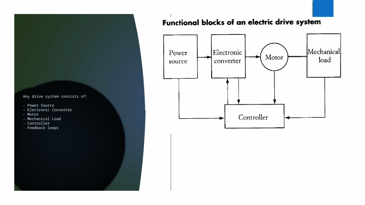
The scheme of elevator structure is shown in Fig. A drive belt is looped over a drive pulley with the ends anchored to the top of the elevator shaft. The electric drive is rigidly attached to the drive pulley with the use of gearing. The car and counterweight, which ride on pulleys, provide belt tension ensuring the toothed belt and drive pulley do not slip. The elevator car and counter-weight are of different weight .
GOAL: IS TO HAVE CONSTANT SPEED AND RESPONSE TIME REGARDLESS OF THE LOAD TORQUE
Mathematical Model of Elevator Electric Drive .
equations that control operation of the elevator can be divided two systems :
- Mechanical system .
- Electrical System .
Mathematical Model of Mechanical System’s
The motion equation of the entire system from the motor’s perspective is:
(1.1)
where:
is the motor’s moment of inertia
is the angular speed of the rotor
B is the friction coefficient of the motor
is the load torque placed on the motor’s shaft

The load torque that is placed on the drive pulley which is mounted on the motor’s shaft is expressed in equ 1.2
(1.2)
is the angular speed of the pulley
is the pulley’s moment of inertia
is the radius of the drive pulleyis the force exerted on the drive pulley
If the elevator car is moving upwards the load force is defined by equ 1.3
(1.3)
where:
is the gravitational constant
is the mass of the car
is the mass of the counter-weight
is the linear speed of the car
The car speed expressed in terms of motor speed is expressed as: (1.4) In Equ. 1.3 the force is affected by the gravitational force and the
inertia of the elevator car , both of which are expressed as: (1.5) (1.6)
The car speed expressed in terms of motor speed is expressed as: (1.4)
Equ. 1.2 The load torque is now expressed as:
(1.7)
Substituting the load torque equation for when the elevator car is moving upwards (Eqn. 1.7) into the motor’s motion equation (Eqn. 1.1), the motion equation of the entire system is obtained as:
(1.8)
and the load torque due to gravity is:
where the equivalent moment of inertia is:
Using gear ratio a (1.11)
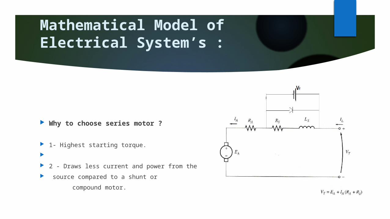
Mathematical Model of Electrical System’s :
Why to choose series motor ?
1- Highest starting torque.
2 - Draws less current and power from the
source compared to a shunt or
compound motor.

In general case we can derive an expression for the motor which is
(2.1)
is Terminal voltage of DC motor
is armature resistance is back e.m.f Voltage Filed inductance
is armature inductance is Filed resistance Filed current
And (2.2)
K is constant is magnetic field is output motor speed [rad/s]
Let (2.3)
From 2.1,2.2 and 2.3 we can get (2.4)
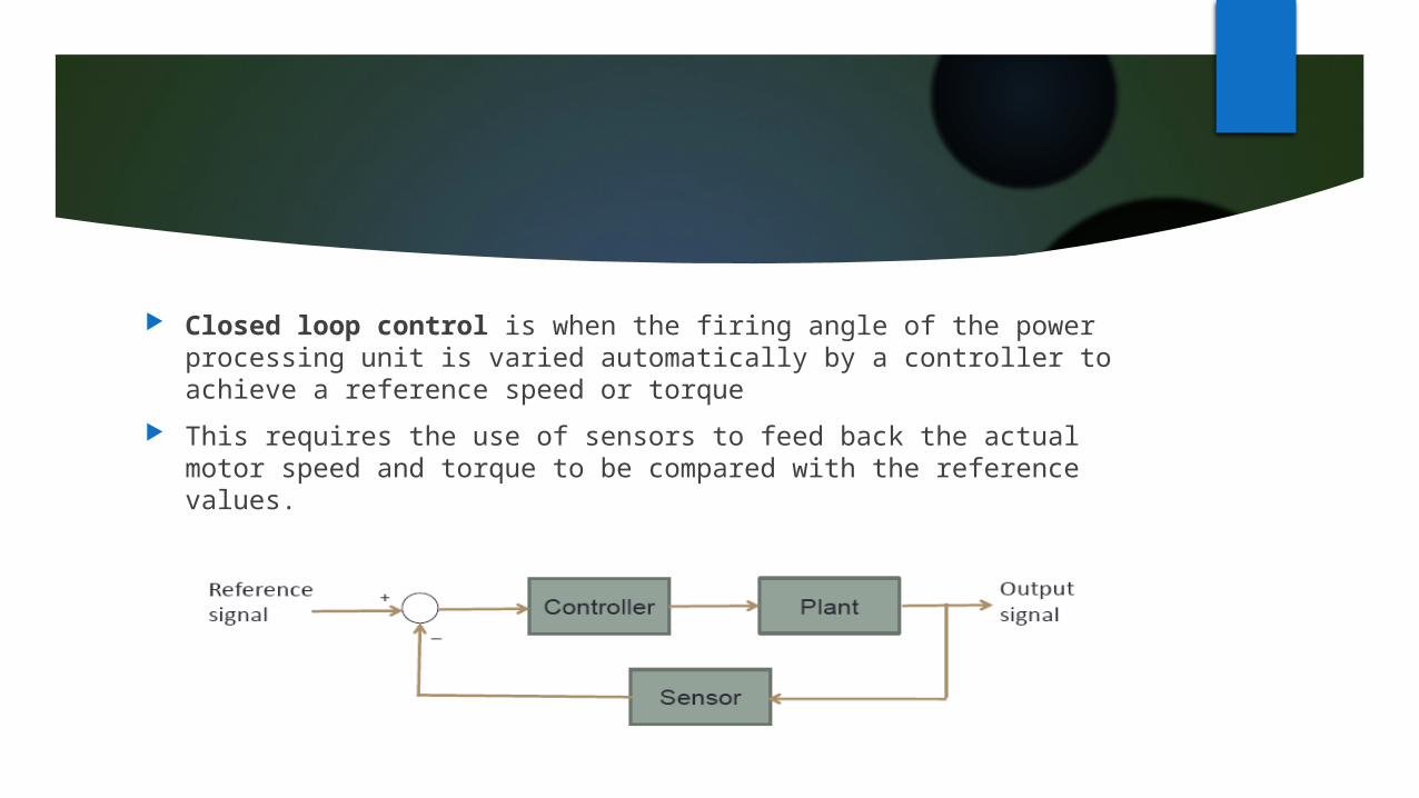
Closed loop control is when the firing angle of the power processing unit is varied automatically by a controller to achieve a reference speed or torque
This requires the use of sensors to feed back the actual motor speed and torque to be compared with the reference values.

•Actual motor speed measured using the tachogenerator (Tach) is filtered to produce feedback signal
•The reference speed is compared to motor obtain a speed error signal
•The speed (PI) controller processes the speed error and produces the torque command Te
•Ia is compared to actual current Ia to obtain a current error signal
•The current (PI) controller processes the error to alter the control signal vc
• vc modifies the firing angle to be sent to the converter to obtained the motor armature voltage for the desired motor operation speed
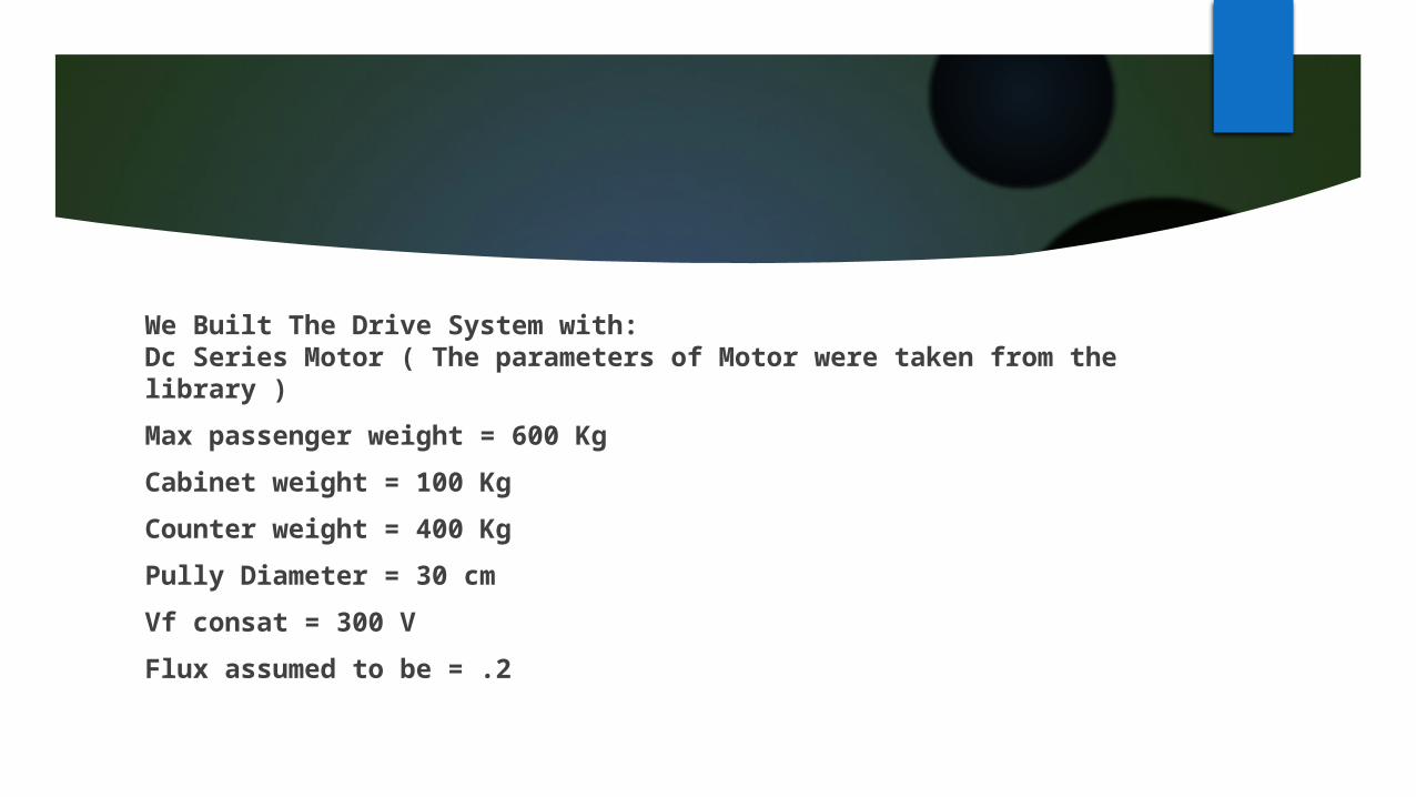
We Built The Drive System with: Dc Series Motor ( The parameters of Motor were taken from the library )
Max passenger weight = 600 Kg
Cabinet weight = 100 Kg
Counter weight = 400 Kg
Pully Diameter = 30 cm
Vf consat = 300 V
Flux assumed to be = .2
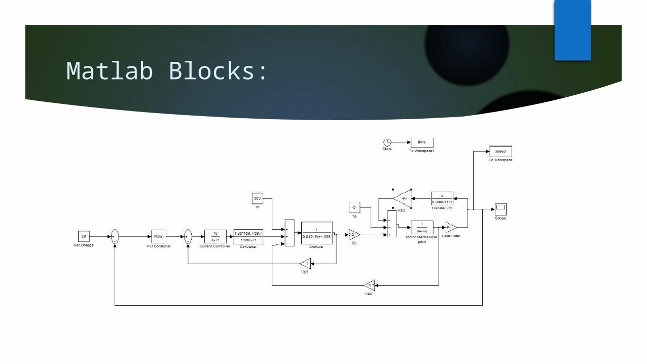
Matlab Blocks:

UpWard
Case 1 : Max : 600 Kg passenger weight ( Total Of 700 Kg with Cabinet )
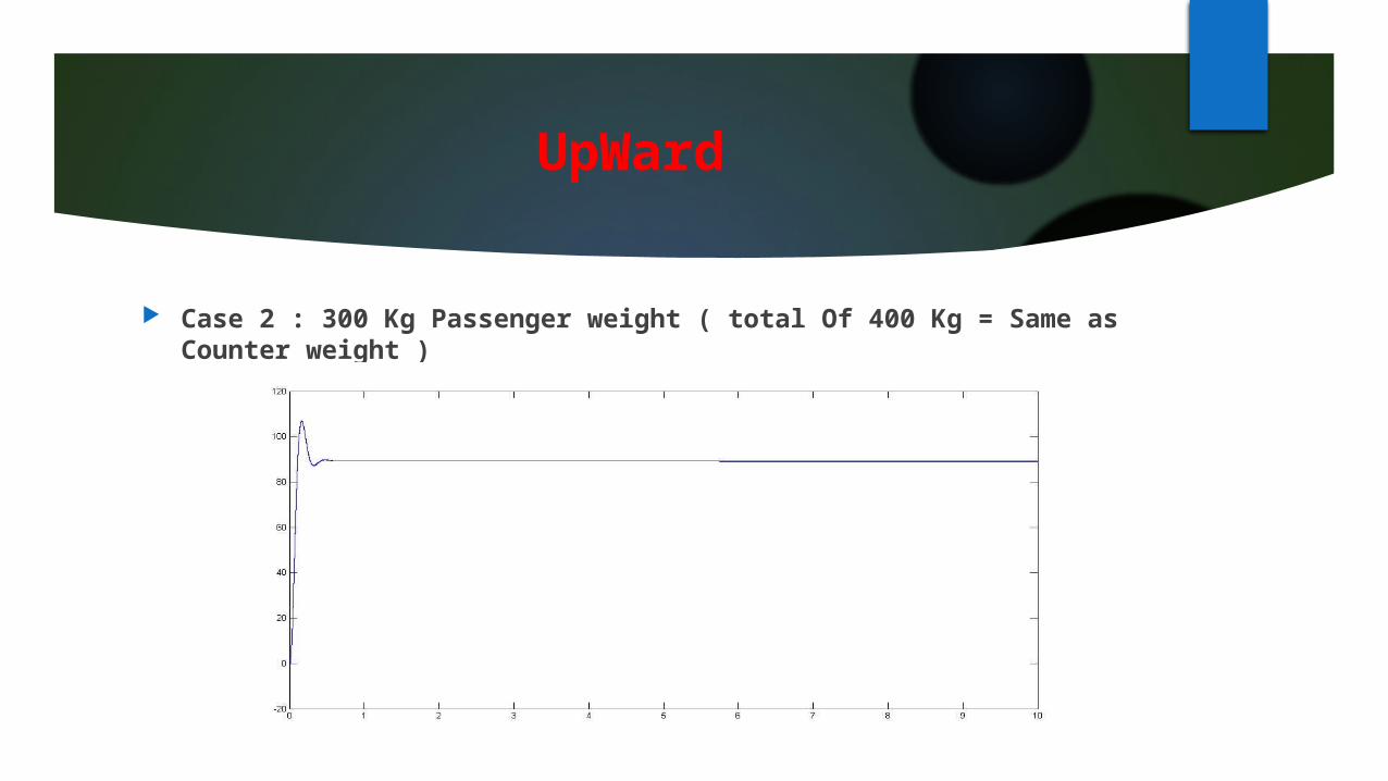
UpWard
Case 2 : 300 Kg Passenger weight ( total Of 400 Kg = Same as Counter weight )
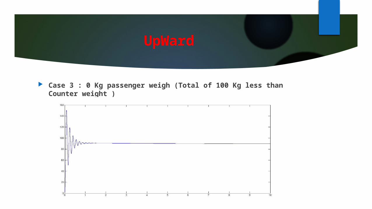
UpWard
Case 3 : 0 Kg passenger weigh (Total of 100 Kg less than Counter weight )
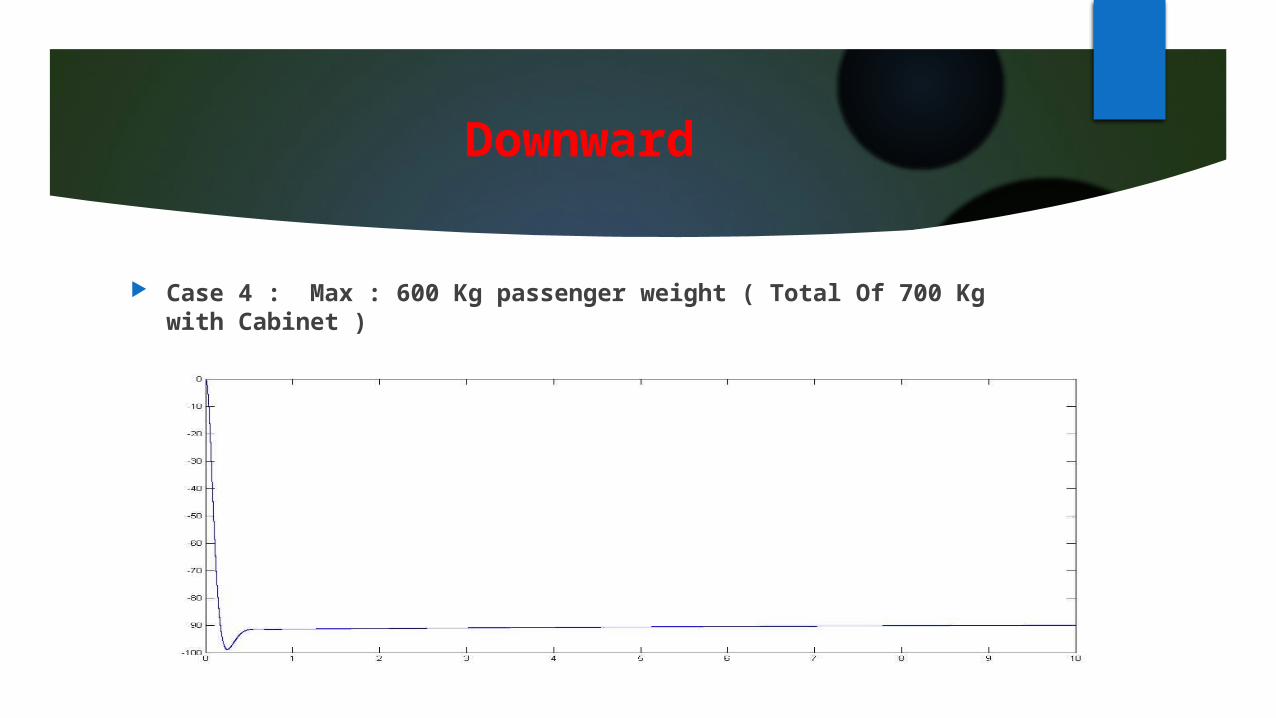
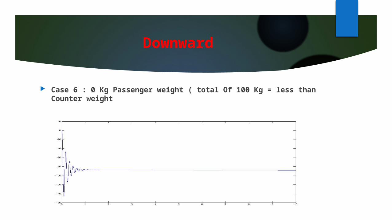
Downward
Case 4 : Max : 600 Kg passenger weight ( Total Of 700 Kg with Cabinet )

Downward
Case 5 : 300 Kg Passenger weight ( total Of 400 Kg = Same as Counter weigh )
Downward
Case 6 : 0 Kg Passenger weight ( total Of 100 Kg = less than Counter weight