Embed Size (px)
Citation preview
Main features: 3-phase energy meter, 3 × 230 / 400 VAC 50 Hz
Direct measurement up to 65 A
Display of active power, voltage and current for every phase
Display of active power for all phases
S0 output
7-digits display for 1 or 2 tariffs
Lead seal possible with cap as accessory
Accuracy class B according to EN50470-3, accuracy class 1 according to IEC62053-21
Electrical energy meter with LCD display and integrated S0 interface. The S0 interface (pronounced S-O-interface) is a hardware interface for the transmission of measured values in building automation.
Electrical Energy Meter with integrated S0-interfaceEEM400-D-P
Order NumberStandard Version: EEM400-D-P MID Version: EEM400-D-P-MIDSealing caps: EEM400-SEALCAP (Bulk with 20 units)
Technical dataPrecision class B according to EN50470-3,
1 according to IEC62053-21Operating voltage 3 × 230 / 400 VAC, 50 Hz
Tolerance -20%/+15%Reference/ measurement current
Iref = 10 A, Imax = 65 A
Starting/ minimum current
Ist = 40 mA, Imin = 0.5 A
Power consumption Active 0.4 W per phaseCounting range 00˙000.00…99˙999.99
100˙000.0…999˙999.9Display LCD backlit, digits 6 mm highDisplay without mains power
Capacitor based LCD, max. 2 times over 10 days
S0 output (interface) Optocoupler max. 30 V / 20 mA and at least 5 V, impedance 100 Ω, pulse width 30 ms
Transmission distance, S0 output
Max. 1000 m (at 30 V /20 mA)
Pulses per kWh LED: 100 pulses/kWh S0 output: 1000 pulses/kWh
MountingMounting On 35 mm rail, according to
EN60715TH35Terminal connections main circuit
Conductor cross-section 1.5…16 mm2, screwdriver Pozidrive no. 1, slot no.2, torque 1.5…2 Nm
Terminal connections control circuit
Conductor cross-section max. 2.5 mm2, screwdriver Pozidrive no. 0, slot no.2, torque 0.8 Nm
Insulation characteristics
4 kV / 50 Hz test according to VDE04356 kV 1.2 / 50 µs surge voltage according to IEC255-4Device protection class II
Ambient temperature –25°…+55 °CStorage temperature –30°…+85 °CRelative humidity 95% at 25°…+40 °C, without
condensation EMC/interference immunity
Surge voltage according to IEC61000-4-5 at main circuit, 4 kV
Burst voltage according to IEC61000-4-4, 4 kVESD according to IEC61000-4-2, contact 8 kV, air 15 kV
2 |
82
27
62
4,5
6
70
65 x 11,7 = (58,5)
768
4,5930,5 9
11
57,7
22,7
35
69,5
3162
70
9
57.7
30.5
22.7
4.5
1135
5 x 11.7 = [58.5] 6
4.5
27
31
4582
69.5
768
6
9
Data sheet – Three-phase Electrical Energy Meter with S0-interface
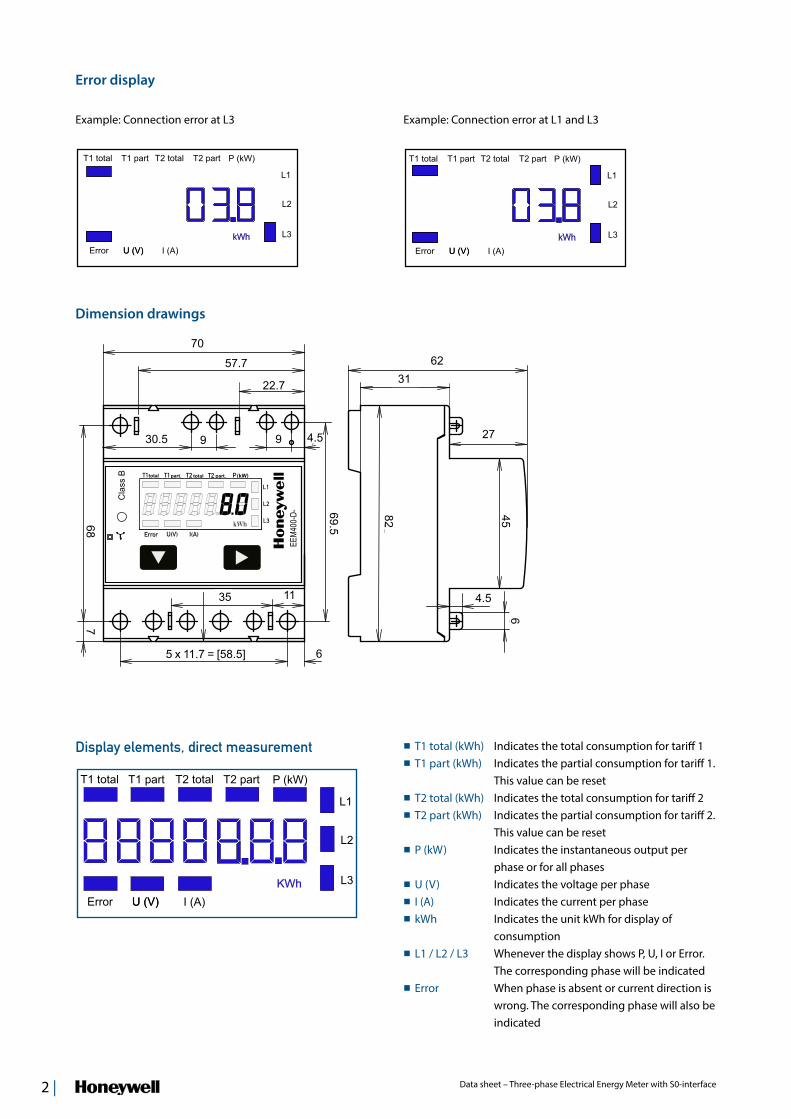
Dimension drawings
Display elements, direct measurement T1 total (kWh) Indicates the total consumption for tariff 1 T1 part (kWh) Indicates the partial consumption for tariff 1.
This value can be reset T2 total (kWh) Indicates the total consumption for tariff 2 T2 part (kWh) Indicates the partial consumption for tariff 2.
This value can be reset P (kW) Indicates the instantaneous output per
phase or for all phases U (V) Indicates the voltage per phase I (A) Indicates the current per phase kWh Indicates the unit kWh for display of
consumption L1 / L2 / L3 Whenever the display shows P, U, I or Error.
The corresponding phase will be indicated Error When phase is absent or current direction is
wrong. The corresponding phase will also be indicated
Error display
Example: Connection error at L1 and L3Example: Connection error at L3
> 3 s
> 3 s
| 3Data sheet – Three-phase Electrical Energy Meter with S0-interface
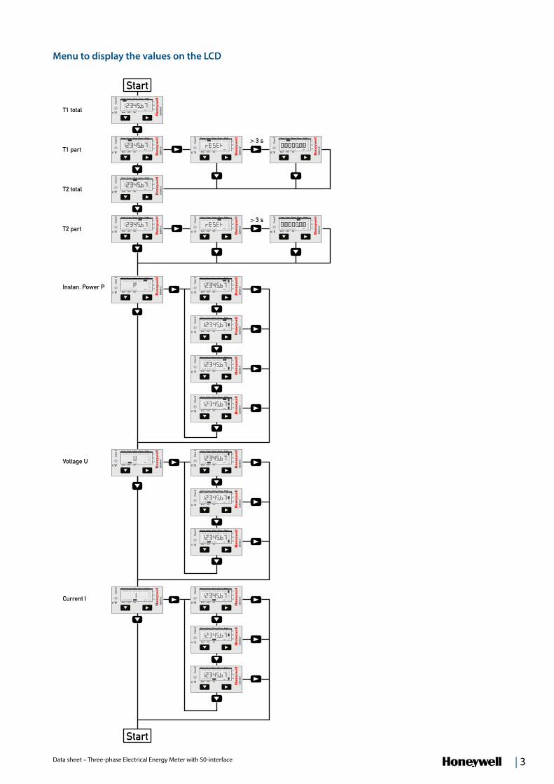
Start
T1 total
T1 part
T2 total
T2 part
Instan. Power P
Menu to display the values on the LCD
Voltage U
Current I
Start
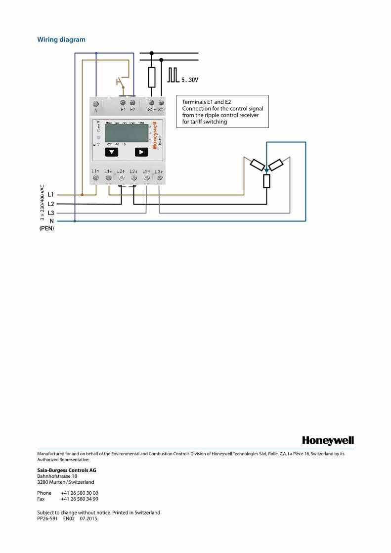
L1
L2L3N
(PEN)
5...30V
3 ×
230/
400
VAC
Manufactured for and on behalf of the Environmental and Combustion Controls Division of Honeywell Technologies Sàrl, Rolle, Z.A. La Pièce 16, Switzerland by its Authorized Representative:
Saia-Burgess Controls AG Bahnhofstrasse 18 3280 Murten / Switzerland
Phone +41 26 580 30 00 Fax +41 26 580 34 99
Subject to change without notice. Printed in Switzerland PP26-591 EN02 07.2015
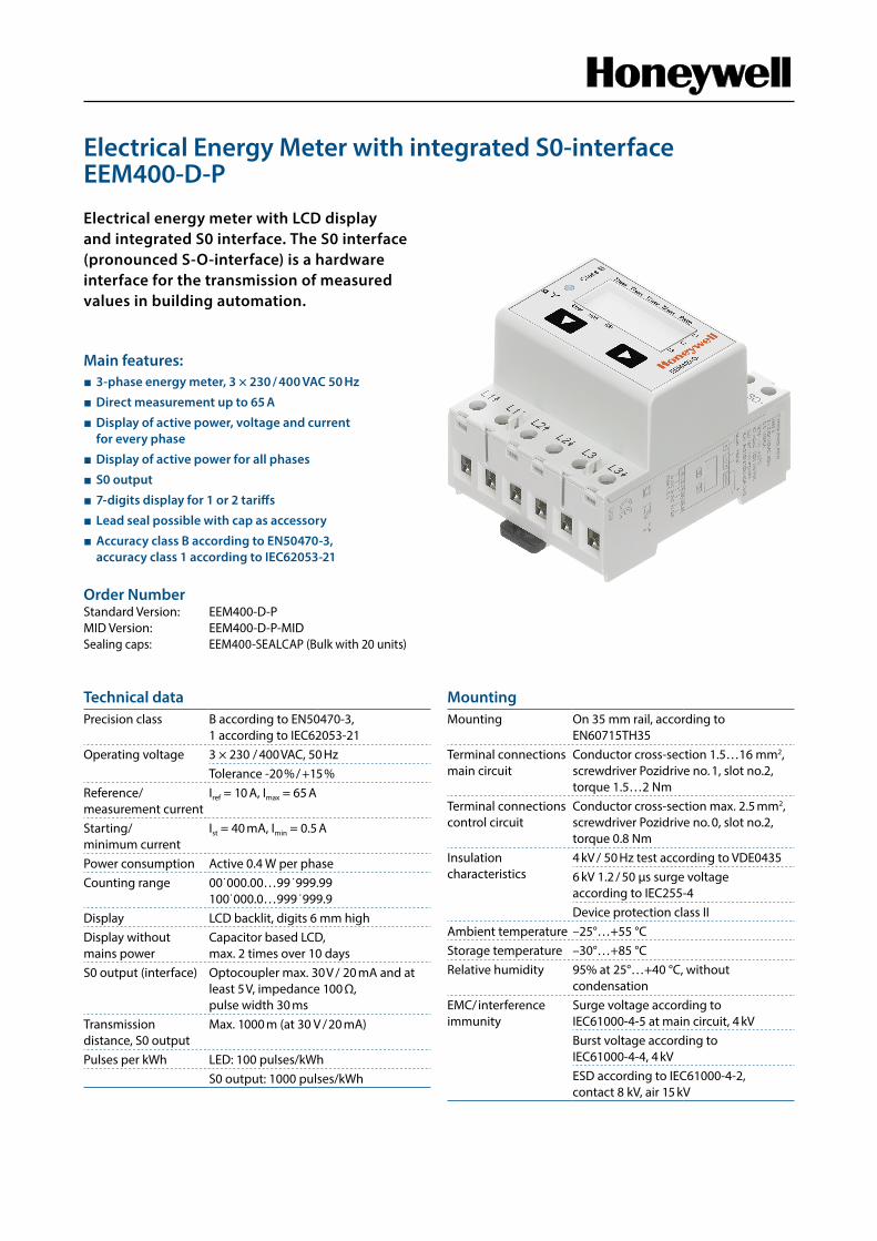
Wiring diagram
Terminals E1 and E2 Connection for the control signal from the ripple control receiver for tariff switching