Embed Size (px)
Citation preview
16Electrical Energy and Capacitance
Clicker Questions
Question L3.01
Description: Relating electrostatic potential to work.
Question
The electric potential at two points in space is: V1 � 200 volts and V
2 � 300 volts. Which of the following
statements is true for moving a point charge q from point 1 to 2?
A. The work done by an external agent to move q from point 1 to 2 is positive.
B. We can’t determine the work done because we don’t know the direction of V at the two points.
C. The work done by the electric force exerted on q in moving it from point 1 to 2 is W � �q(100 V).
1. A 2. B 3. C 4. A and B 5. A and C 6. B and C 7. A, B, and C 8. None of the above
Commentary
Purpose: To link the concepts of electrostatic potential and work.
Discussion: The work done by an electric fi eld on a moving charge is equal to the negative of the charge times the change in electric potential between the two points: W q V V= − =∆ ∆. V100 , so statement C is correct.
Statement A is true only for positive charges, and we aren’t told whether q is positive or negative. In par-ticular, the work done on q by an external agent is q V∆ , whether the charge is positive or negative. Also, the total work done on the charge is zero, so the work done by the electric force is −q V∆ .
Statement B is nonsense: the electrostatic potential V doesn’t have a direction. It’s a scalar fi eld. (The electric fi eld E is a vector and has a direction.)
So, (3) is the best answer.
39
56157_16_ch16_p039-085.indd 3956157_16_ch16_p039-085.indd 39 3/18/08 1:22:45 PM3/18/08 1:22:45 PM
40 Chapter 16
Key Points:
• The work done by an electric fi eld on a moving charge is W q V= − ∆ .
• Whether the work done on a charge moving in an electric fi eld is positive or negative depends on the sign of the charge, and whether you’re talking about the work done by the fi eld or by an external agent moving it in the fi eld.
• Electric potential is a scalar, not a vector, fi eld.
For Instructors Only
If any students include statement B (answers 2, 4, 6, or 7), it should be thoroughly discussed as it indicates a possible confusion between electric fi elds and electric potentials.
If students have diffi culty understanding statement C, especially the presence of the minus sign, it may help to describe the situation in terms of electric fi eld lines pointing from higher to lower potential, and charges moving with or against the fi eld.
You can also invoke conservation of energy to explain the work done by the electric force. The total work done on the charge is zero, since its kinetic energy does not change. In moving a positive charge to a higher potential (think about pushing a boulder up a hill), positive work must be done by an external agent, so negative work must be done by the electric force, the only other force in the situation. In moving a negative charge to a higher potential, negative work must be done by an external agent, so positive work must be done by the electric force.
Note that, properly speaking, the charge “q” does not possess any electric potential energy. The system does.
Question L3.02
Description: Introducing the concept of “conservative force” for electrostatics.
Question
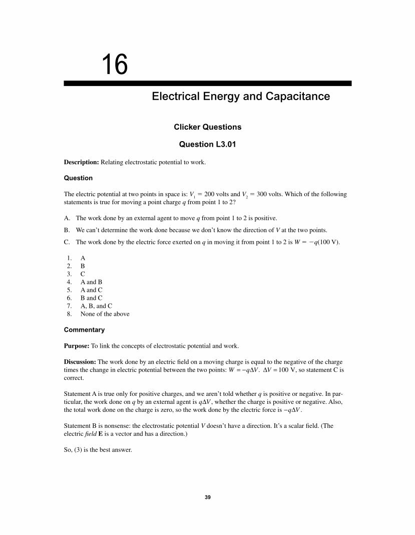
Two point charges are fi xed on the x-axis. Imagine moving a positive charge from point P to the origin along the different paths shown in the diagram. For which path would you do the most work?
P
Path B
Path B
Path D
a–aqq
Path A
Path C
Path C
Path D
56157_16_ch16_p039-085.indd 4056157_16_ch16_p039-085.indd 40 3/18/08 1:22:46 PM3/18/08 1:22:46 PM
Electrical Energy and Capacitance 41
1. Path A 2. Path B 3. Path C 4. Path D 5. Cannot be determined 6. None of the above
Commentary
Purpose: To develop your understanding of what a conservative force is.
Discussion: The electrostatic force is conservative. That means moving a charge from one point in space to another takes the same amount of work no matter what path is followed. Thus, all four paths require the same work, so the best answer is (6), none of the above.
Because the electrostatic force is conservative, it is possible to defi ne an electrostatic potential, and say that the work done on the charge is equal to the change in potential energy of the system. (In the same way, the gravitational force is conservative, so it takes the same amount of work to push an object to the top of a frictionless hill no matter what path up the hill is taken — an amount of work equal to the gravitational potential energy gained.)
Key Points:
• The electrostatic force is conservative, meaning the work required to move a charge between two points is path independent.
• We can defi ne a potential for a conservative force, so that the work done is equal to the change in potential energy of the system.
For Instructors Only
As always, ask students who pick “none of the above” what answer they would pick if it were present. In this case, their response distinguishes those who are correct from incorrect reasons for selecting (6).
Exactly how this question is handled depends on when you use it. It can be employed relatively early as a way to introduce the electrostatic potential, or later to check whether students understand the relationship between work and potential.
A good follow-up question is to ask how much work would be done if one of the fi xed charges on the x-axis were negative.
Question L3.03
Description: Introducing work in an electrostatic context.
Question
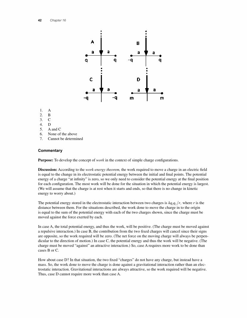
For the following situations consider moving a positive charge from very far away to the origin along the y-axis. For which situation would you do the most work?
56157_16_ch16_p039-085.indd 4156157_16_ch16_p039-085.indd 41 3/18/08 1:22:47 PM3/18/08 1:22:47 PM
42 Chapter 16
1. A 2. B 3. C 4. D 5. A and C 6. None of the above 7. Cannot be determined
Commentary
Purpose: To develop the concept of work in the context of simple charge confi gurations.
Discussion: According to the work-energy theorem, the work required to move a charge in an electric fi eld is equal to the change in its electrostatic potential energy between the initial and fi nal points. The potential energy of a charge “at infi nity” is zero, so we only need to consider the potential energy at the fi nal position for each confi guration. The most work will be done for the situation in which the potential energy is largest. (We will assume that the charge is at rest when it starts and ends, so that there is no change in kinetic energy to worry about.)
The potential energy stored in the electrostatic interaction between two charges is kq q r1 2 , where r is the distance between them. For the situations described, the work done to move the charge in to the origin is equal to the sum of the potential energy with each of the two charges shown, since the charge must be moved against the force exerted by each.
In case A, the total potential energy, and thus the work, will be positive. (The charge must be moved against a repulsive interaction.) In case B, the contribution from the two fi xed charges will cancel since their signs are opposite, so the work required will be zero. (The net force on the moving charge will always be perpen-dicular to the direction of motion.) In case C, the potential energy and thus the work will be negative. (The charge must be moved “against” an attractive interaction.) So, case A requires more work to be done than cases B or C.
How about case D? In that situation, the two fi xed “charges” do not have any charge, but instead have a mass. So, the work done to move the charge is done against a gravitational interaction rather than an elec-trostatic interaction. Gravitational interactions are always attractive, so the work required will be negative. Thus, case D cannot require more work than case A.
56157_16_ch16_p039-085.indd 4256157_16_ch16_p039-085.indd 42 3/18/08 1:22:47 PM3/18/08 1:22:47 PM
Electrical Energy and Capacitance 43
Key Points:
• The work required to change the position of a charge in an electrostatic fi eld is equal to the change in electrostatic potential energy that occurs, assuming kinetic energy does not change (the work-energy theorem).
• The electrostatic potential energy of a point charge q1 interacting with another point charge q
2 a
distance r away is given by kq q r1 2 .
• The electrostatic potential energy of a point charge interacting with a set of point charges is the sum of its potential energy due to each of those charges alone (superposition).
• Electrostatic potential energy can be positive or negative.
For Instructors Only
This is a useful question for beginning a discussion about electrostatic work, leading towards the introduc-tion of the electric potential.
Some students who may select answer (7) on the grounds that they are not explicitly told the charges of the masses in case D are not incorrect, though they are not using all the information inherent in the question and its context to infer the intent of the question.
Students choosing answer (5) probably don’t appreciate that electrostatic potential energy can be positive or negative, or are considering only the magnitude of the work.
Question L3.04
Description: Integrating energy conservation ideas with electrostatics.
Question
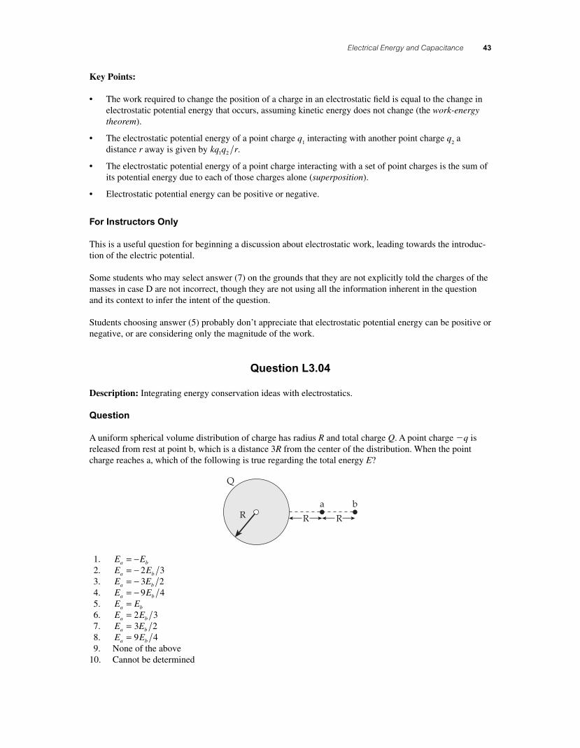
A uniform spherical volume distribution of charge has radius R and total charge Q. A point charge �q is released from rest at point b, which is a distance 3R from the center of the distribution. When the point charge reaches a, which of the following is true regarding the total energy E?
Q
Ra b
R R
1. E Ea b= − 2. E Ea b= − 2 3 3. E Ea b= − 3 2 4. E Ea b= − 9 4 5. E Ea b= 6. E Ea b= 2 3 7. E Ea b= 3 2 8. E Ea b= 9 4 9. None of the above 10. Cannot be determined
56157_16_ch16_p039-085.indd 4356157_16_ch16_p039-085.indd 43 3/18/08 1:22:55 PM3/18/08 1:22:55 PM
44 Chapter 16
Commentary
Purpose: To revisit energy conservation in the context of an electricity problem.
Discussion: Note that the question asks about the total energy of the system, not the potential energy. No non-conservative forces act on the system, so total energy must be conserved. Thus, the correct answer is (5).
When the point charge moves inward, the potential energy decreases (becomes more negative), offsetting the increase in kinetic energy as the point charge speeds up.
Key Points:
• Be careful not to confuse kinetic, potential, and total energy.
• Ideas you learned in mechanics, such as the work-energy theorem and conservation of energy principle, apply to electromagnetic systems as well.
For Instructors Only
Students often “pigeonhole” their learning, and don’t think to apply ideas they learned in one course or topic area to later topics. Cross-topic questions like this one help to overcome that. Students answering (7) are likely providing the right answer to the wrong question, and answering for the potential rather than the total energy. Students selecting many of the other choices may be doing the same thing, but incorrectly.
Question L3.05
Description: Relating and distinguishing electric fi eld and electric potential.
Question
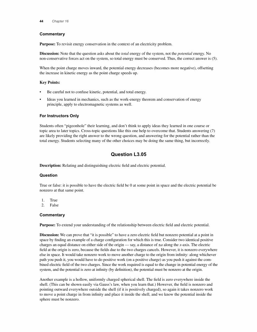
True or false: it is possible to have the electric fi eld be 0 at some point in space and the electric potential be nonzero at that same point.
1. True 2. False
Commentary
Purpose: To extend your understanding of the relationship between electric fi eld and electric potential.
Discussion: We can prove that “it is possible” to have a zero electric fi eld but nonzero potential at a point in space by fi nding an example of a charge confi guration for which this is true. Consider two identical positive charges an equal distance on either side of the origin — say, a distance of ±a along the x-axis. The electric fi eld at the origin is zero, because the fi elds due to the two charges cancels. However, it is nonzero everywhere else in space. It would take nonzero work to move another charge to the origin from infi nity: along whichever path you push it, you would have to do positive work (on a positive charge) as you push it against the com-bined electric fi eld of the two charges. Since the work required is equal to the change in potential energy of the system, and the potential is zero at infi nity (by defi nition), the potential must be nonzero at the origin.
Another example is a hollow, uniformly charged spherical shell. The fi eld is zero everywhere inside the shell. (This can be shown easily via Gauss’s law, when you learn that.) However, the fi eld is nonzero and pointing outward everywhere outside the shell (if it is positively charged), so again it takes nonzero work to move a point charge in from infi nity and place it inside the shell, and we know the potential inside the sphere must be nonzero.
56157_16_ch16_p039-085.indd 4456157_16_ch16_p039-085.indd 44 3/18/08 1:23:01 PM3/18/08 1:23:01 PM
Electrical Energy and Capacitance 45
Key Points:
• To fi gure out if a statement is true or false, it sometimes helps to fi nd an example.
• The electrostatic potential is not necessarily zero where the electric fi eld is (and vice-versa).
• The electrostatic potential at a point in space is equal to the work required to move a charged point there from infi nity (by any path), divided by the point’s charge.
For Instructors Only
Before revealing which answer is correct, ask students choosing answer (1) to draw or describe a charge confi guration satisfying the statement. (This is often suffi cient to make them change their mind.) Ask stu-dents choosing (2) to prove it.
Question L3.06a
Description: Distinguishing the electric potential created by a charge distribution from the electric poten-tial energy of the distribution.
Question
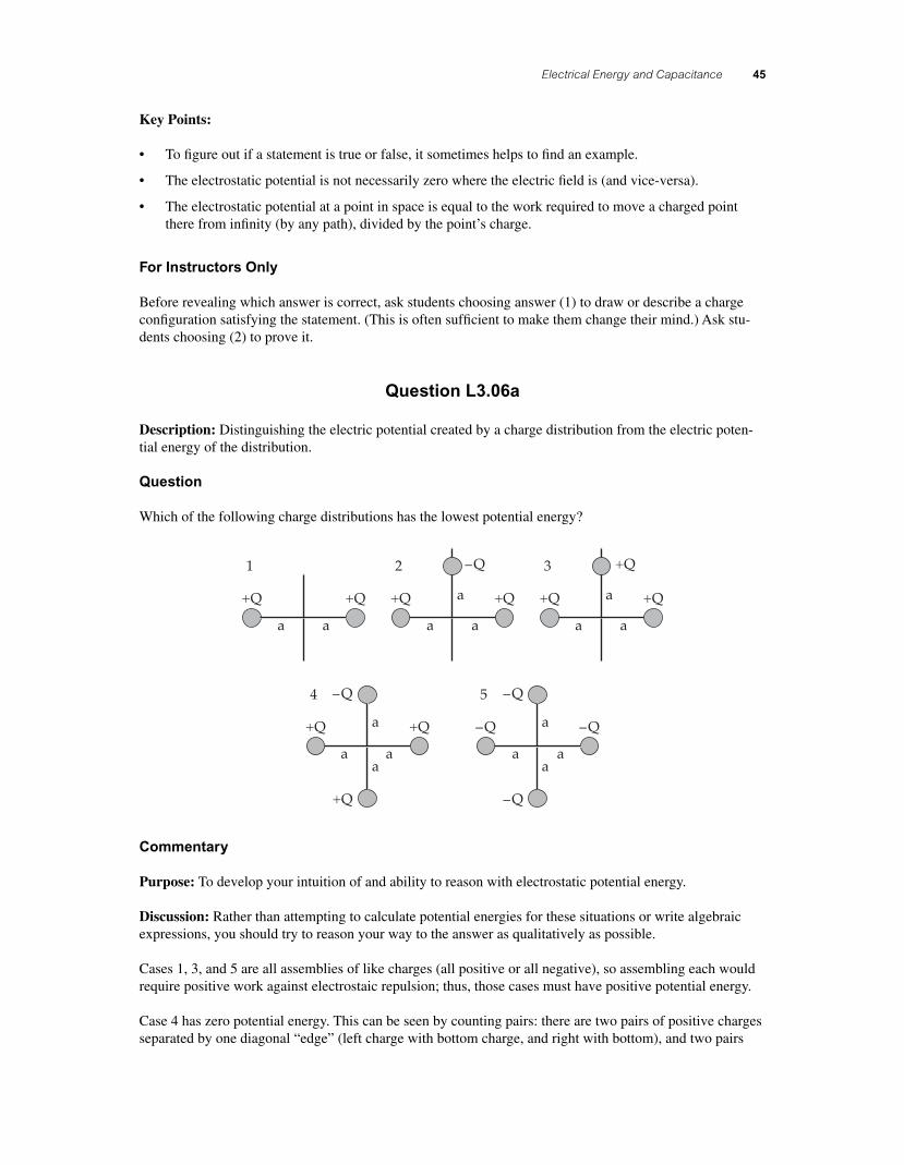
Which of the following charge distributions has the lowest potential energy?
+Q +Q +Q +Q +Q +Q
–Q
–Q +Q
–Q
–Q
+Q
–Q
–Q+Q +Q
1 2
a a a a a a
a aa aa
a
a
a
a a
3
4 5
Commentary
Purpose: To develop your intuition of and ability to reason with electrostatic potential energy.
Discussion: Rather than attempting to calculate potential energies for these situations or write algebraic expressions, you should try to reason your way to the answer as qualitatively as possible.
Cases 1, 3, and 5 are all assemblies of like charges (all positive or all negative), so assembling each would require positive work against electrostaic repulsion; thus, those cases must have positive potential energy.
Case 4 has zero potential energy. This can be seen by counting pairs: there are two pairs of positive charges separated by one diagonal “edge” (left charge with bottom charge, and right with bottom), and two pairs
56157_16_ch16_p039-085.indd 4556157_16_ch16_p039-085.indd 45 3/18/08 1:23:01 PM3/18/08 1:23:01 PM
46 Chapter 16
of opposite charges separated by that same distance (top with left, top with right). These four pairs will all have the same magnitude of potential energy, but the like-charge pairs will have positive energy and the opposite-charge pairs will have negative, so the total potential energy from these four parings will be zero. Likewise, there is one pair of like charges a distance 2a apart, and one pair of opposite charges the same distance apart, so the potential energy from these two pairs will cancel. Thus, the total potential energy of the confi guration must be zero.
Another way to fi gure this out for Case 4 is to imagine constructing a pair of positive charges separated by 2a. This will require some positive amount of work. Then, infi nitely far from the fi rst pair, assemble a positive-and-negative pair also separated by 2a. This will require the same magnitude of work, but negative since the charges attract. Place the opposite-charge pair in the position shown along the y-axis; this requires no work. Now, move the positive pair into place, sliding it along the x-axis from infi nity. This also requires no work, since every point along that axis is equidistant from the positive and negative charges of the fi rst pair. Result: zero net work to construct the charge arrangement.
Case 2 must have negative potential energy, since it has two opposite-charge pairs with a relatively short separation (negative potential due to attractive interaction) and one like-charge pair with a larger separation (positive potential). So, Case 2 must have the least potential energy of all the confi gurations.
Key Points:
• Whenever possible, attempt to answer questions via qualitative reasoning rather than algebraic manipulations. You’ll learn more, and be less likely to commit a math slip.
• The potential energy of a complex charge confi guration can be thought of as the sum of potential energies of each pair of charges.
• The potential energy stored in the interaction between two like charges is positive; that stored between two opposite charges is negative.
For Instructors Only
Depending on their comfort level with potential energy and work, students may struggle with the qualita-tive arguments used here. We recommend spending the time necessary for them to fully grasp them (especially for Case 4); it will pay dividends later.
A good follow-up question is to ask students to order the cases according to increasing potential energy.
Question L3.06b
Description: Distinguishing the electric potential created by a charge distribution from the electric potential energy of the distribution.
Question
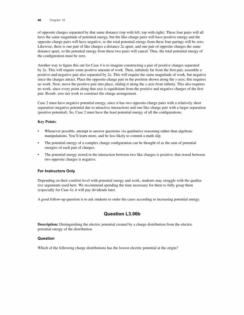
Which of the following charge distributions has the lowest electric potential at the origin?
56157_16_ch16_p039-085.indd 4656157_16_ch16_p039-085.indd 46 3/18/08 1:23:02 PM3/18/08 1:23:02 PM
Electrical Energy and Capacitance 47
+Q +Q +Q +Q +Q +Q
–Q
–Q +Q
–Q
–Q
+Q
–Q
–Q+Q +Q
1 2
a a a a a a
a aa aa
a
a
a
a a
3
4 5
Commentary
Purpose: To develop your ability to reason with electrostatic potential energy, and distinguish the potential energy of a charge confi guration from the potential it creates in space around it.
Discussion: The electrostatic potential at some point due to an assembly of charges is the sum of the potentials due to each individual charge (“superposition”). Let’s say the potential due to a positive charge �Q a distance a away is U. The potential due to a negative charge the same distance away must be −U . So, distribution (1) has potential 2U at the origin, (2) has U, (3) has 3U, (4) has 2U, and (5) has − 4U . Thus, distribution (5) creates the lowest electrostatic potential at the origin.
Key Points:
• The electric potential of a distribution of charges is the sum of the potentials due to each individual charge (“superposition”).
• Potential is a scalar. It can be positive or negative, but has no direction.
• The potential created by a charge distribution is not the same as the potential energy stored in the distribution (i.e., the energy required to assemble it).
For Instructors Only
Juxtaposed with the previous question, this serves to highlight the difference between the potential energy stored in a distribution from the potential created by the distribution at some point.
You may wish to stress that when potentials due to point charges are determined, a reference point at infi n-ity is assumed.
56157_16_ch16_p039-085.indd 4756157_16_ch16_p039-085.indd 47 3/18/08 1:23:02 PM3/18/08 1:23:02 PM
48 Chapter 16
Question N3.01
Description: Developing understanding of capacitors as circuit elements: series.
Question
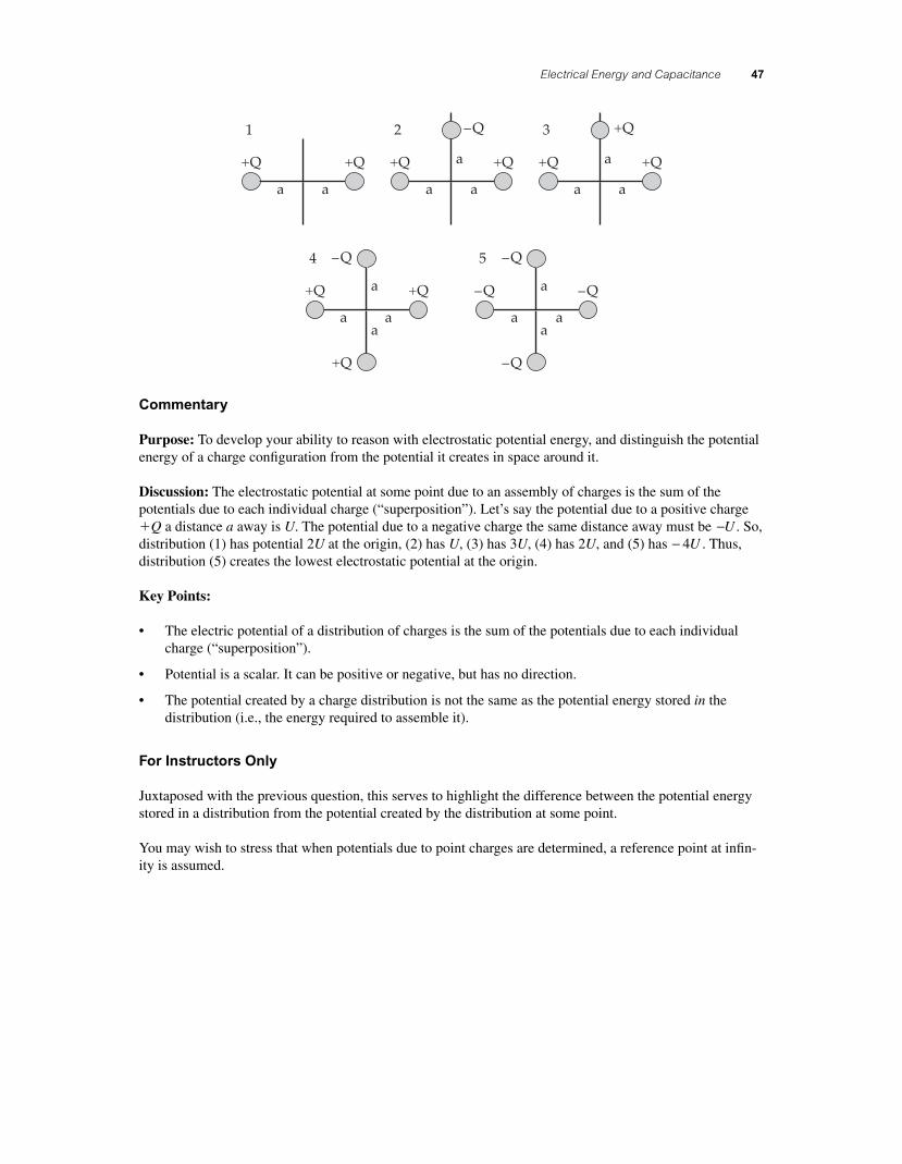
A capacitor, C1, is connected to a battery until charged, and then disconnected from the battery. A second
capacitor, C2, is connected in series to the fi rst capacitor. What changes occur in capacitor C
1 after C
2 is
connected as shown?
VV C1
C1
C1
C2Q
–Q
Q
–Q
1. ∆V same, Q increases, U increases 2. ∆V same, Q decreases, U same 3. ∆V increases, Q decreases, U increases 4. ∆V decreases, Q same, U decreases 5. ∆V decreases, Q decreases, U decreases 6. None of the above 7. Cannot be determined
Commentary
Purpose: To improve your understanding of capacitors by reasoning about their behavior.
Discussion: Once the battery is disconnected, the charge on the capacitor’s plates cannot change. When the second capacitor is connected in series to one of C
1’s ends, the charge on C
1 still can’t change. The charge
on the lower plate can’t go anywhere, and although some of the opposite charge on the upper plate could conceivably move to the connected plate of C
2, it won’t because it is attracted to the charge on the lower
plate. The charge on one plate of a capacitor will always be equal in magnitude and opposite in sign to the charge on the other. (All the electric fi eld lines from one plate travel across the gap and terminate on the other, so the amount of charge must be the same.) So, Q remains the same.
Since the physical dimensions of C1 don’t change and no material enters or leaves its gap, its capacitance
doesn’t change. According to C Q V= ∆ , if the capacitance and the charge are both constant, the potential difference ∆V must also be. The energy stored in a capacitor is U C V= ( )1
22∆ , so the stored energy remains
the same as well.
All quantities remain the same, so the best answer is (6), “None of the above.”
Key Points:
• The charge on one plate of a parallel-plate capacitor will always be equal in magnitude and opposite in sign to the charge on the other plate.
• The charge must stay the same on a disconnected capacitor: it has nowhere to go.
• A capacitor’s capacitance depends on its physical construction (dimensions and materials), not on conditions such as the charge on its plates or the potential difference across its ends.
56157_16_ch16_p039-085.indd 4856157_16_ch16_p039-085.indd 48 3/18/08 1:23:02 PM3/18/08 1:23:02 PM
Electrical Energy and Capacitance 49
For Instructors Only
Despite the fi gure, students sometimes think the second capacitor is connected in parallel to the fi rst rather than in series. This may be indicated by their choice of answer (5), though that is not the only possible reason for such a choice.
The issue most likely to need discussion is whether the charge on the upper plate of C1 stays put, or distrib-
utes itself across the two now-connected plates of C1 and C
2. The argument against the latter is outlined in
the discussion, but may require elaboration, the drawing of fi eld line diagrams, and the like.
Depending upon the course it may be profi table to digress into a discussion of an ideal versus a non-ideal capacitor that can leak its charge.
Question N3.02
Description: Developing understanding of capacitors as circuit elements: parallel.
Question
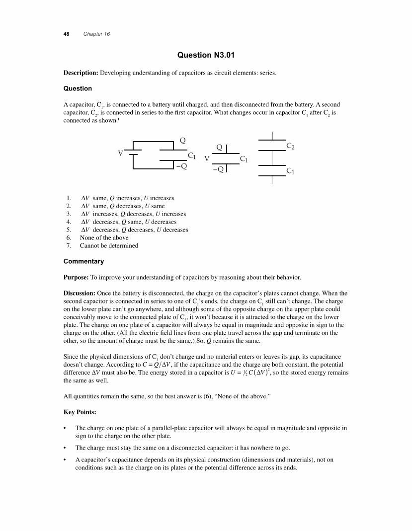
A capacitor, C1, is connected to a battery until charged, then disconnected from the battery. A second
capacitor, C2, is connected in parallel to the fi rst capacitor. Which statements below are true?
V V
C1
C1
C1 C2Q
–Q
Q
–Q
1. Charge on C1 decreases.
2. Total charge on C1 and C
2 is the same as the original Q.
3. The total energy stored in both capacitors is the same as the original U stored in C1.
4. The potential difference (voltage) across C1 decreases.
5. All of the above 6. Only 1, 2, and 3 are true. 7. Only 1, 2, and 4 are true. 8. None of the above
Commentary
Purpose: To improve your understanding of capacitors by reasoning about their behavior.
Discussion: When capacitor C1 is removed from the battery, it has a charge �Q on one plate and −Q on
the other. When the second capacitor is connected in parallel, some of that charge will fl ow to the plates of the other capacitor. C
1 will now have a charge of Q
1 on it (�Q
1 on one plate and −Q1 on the other), and C
2
will have a charge of Q2, where Q
1 � Q
2 � Q. Thus, the charge on C
1 decreases (statements 1 and 2).
Since the physical construction of C1 doesn’t change, neither does its capacitance. Therefore, since
C Q V= Δ , the potential difference ΔV across C1 must decrease (statement 4).
The energy stored on a capacitor is U C V Q C= ( ) = ( )12
2 2 2Δ . To make the analysis easier, let’s assume C
1 = C
2. In that case, Q Q Q1 2
12= = . The original energy stored on C
1 was U Q Ci = ( )2
12 , and the fi nal energy stored on both capacitors is U Q C Q C Q Cf = ( ) + ( ) = ( )1
21 2
22
212 2 4 , so U Uf i= 1
2 . The total stored energy decreases. If the capacitances are not equal, the factor will not be 1
2 , but the energy will still decrease.
Thus, the best answer is (7).
56157_16_ch16_p039-085.indd 4956157_16_ch16_p039-085.indd 49 3/18/08 10:25:01 PM3/18/08 10:25:01 PM
50 Chapter 16
(If you’re wondering where the lost energy went, it was dissipated as heat by the wires as charge fl owed between the capacitors. Wires are never perfectly conducting, and this is a case where even the very small resistance of “ideal” wires matters.)
Key Points:
• When dealing with capacitors, fi gure out what stays constant. When capacitors are isolated, charge remains constant. When capacitors are connected, charge can be shared. When a battery is connected, voltage remains constant.
• Event though total charge may stay the same, if it moves around, total stored energy can decrease.
• When charge spontaneously redistributes itself by fl owing along a conductor, it decreases the total potential energy of the system.
For Instructors Only
Statement (3) is the most diffi cult for students to reason about. We simplifi ed the discussion by assuming equal capacitances, but the general case can be proven (with additional algebra).
Question N3.01 serves as good preparation for this question. This question makes a good lead-in for intro-ducing the equivalent capacitance of capacitors in parallel.
Some students may be ready for a discussion of how the energy was lost. Having them insert a resistance and determine the dissipated energy is instructive.
Question N3.03
Description: Understanding the mechanism of capacitance.
Question
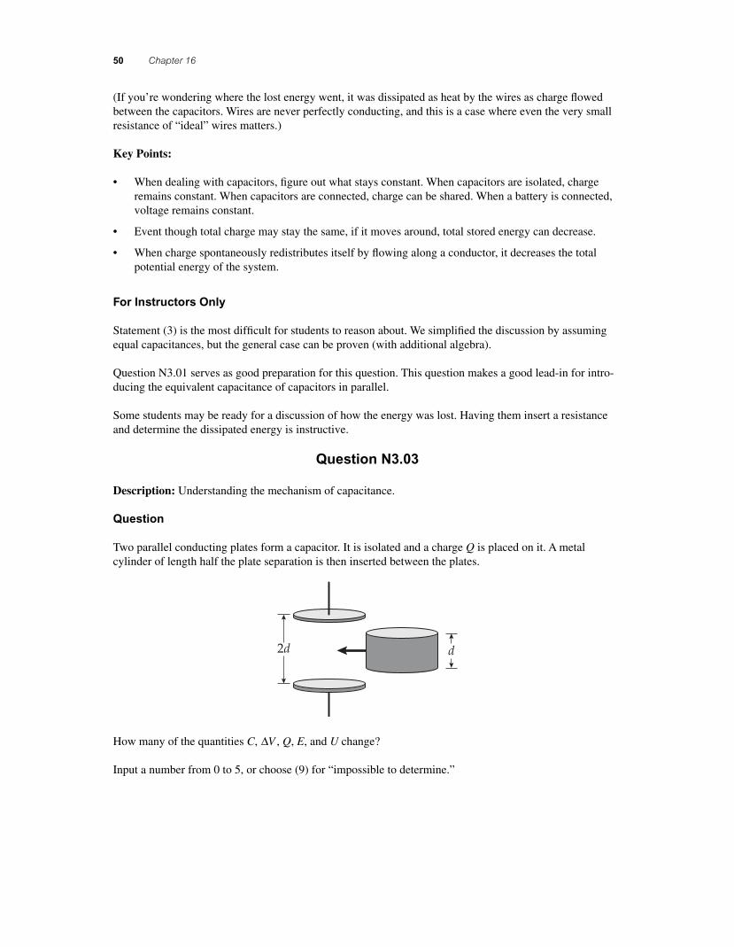
Two parallel conducting plates form a capacitor. It is isolated and a charge Q is placed on it. A metal cylinder of length half the plate separation is then inserted between the plates.
2d d
How many of the quantities C, ∆V , Q, E, and U change?
Input a number from 0 to 5, or choose (9) for “impossible to determine.”
56157_16_ch16_p039-085.indd 5056157_16_ch16_p039-085.indd 50 3/18/08 1:23:10 PM3/18/08 1:23:10 PM
Electrical Energy and Capacitance 51
Commentary
Purpose: To hone your understanding of capacitors and develop your analysis skills.
Discussion: The order in which we consider the quantities C, ΔV , Q, E, and U is critical to fi guring out which change and which do not. It also helps to have a fl exible view of what a “capacitor” is.
The arrangement is “isolated,” which means it is not connected to anything (such as a battery or other power source, or another capacitor). This is useful, because it means that the charge on the outer plates cannot change. In other words, even though a cylinder has been inserted into the gap between the plates, no charge can fl ow onto or off the plates, because there are no conducting paths. This means that Q cannot change.
There can be no electric fi eld inside a conductor. When a conductor is placed inside a region of space with an electric fi eld, charge will fl ow within it such that positive and negative charge are induced on opposite faces of the cylinder, until the net electric fi eld inside the conductor is zero. If we assume that �Q is origi-nally located on the upper plate of the capacitor and �Q on the lower one, then �Q will be induced on the upper surface of the cylinder and �Q on its lower surface. Note that the “charge on the capacitor” still has not changed: it is still Q. Note also that this new arrangement is like having two capacitors in series, with the cylinder itself serving as the wire connecting the two capacitors.
The electric fi eld E between the plates of a capacitor is uniform and depends only on the charge density on each plate. Thus, since the area and charge has not changed, the electric fi eld E has not changed either. However, if we look at the entire gap, the electric fi eld within the cylinder is now zero, where it was nonzero in that region before. In other words, in the gap but outside the cylinder the electric fi eld has not changed; the electric fi eld has changed only in the region now occupied by the cylinder.
The potential difference ΔV depends on two factors, the strength of the electric fi eld E and the size of the gap between two plates. Since the electric fi eld is constant, the original potential difference is ΔV E d Ed= ( )( ) =2 2 . The effective gap size changes from 2d to d when the cylinder is inserted, so ΔV will change as well.
Since the charge Q has not changed, but the potential difference ΔV has changed, the capacitance C has changed C Q V=( )Δ .
Since C has changed, but Q has not changed, the potential energy U stored in the capacitor has changed U Q C=( )1
22 . Note that using the alternative form for the potential energy, U C V= ( )1
22Δ , we cannot tell
immediately if U has changed, since C has increased and ΔV has decreased. The other form is more useful, because only one of the quantities has changed (C ).
Thus, only Q remains the same. The rest of the quantities change.
Key Points:
• When analyzing situations where something changes, start by identifying what quantities are held constant.
• The capacitance of a capacitor depends on what materials fi ll the gap between its plates.
• In a static (steady-state) situation, the electric fi eld within a conducting material must be zero. If a conducting object is placed in an electric fi eld, charge will rearrange itself on the object's surface so that the fi eld becomes zero inside.
• The capacitance of a capacitor relates the charge on its plates to the potential difference across it via C Q V= Δ .
• The energy stored in a charged capacitor is given by U C V= ( )12
2Δ .
56157_16_ch16_p039-085.indd 5156157_16_ch16_p039-085.indd 51 3/18/08 11:28:02 PM3/18/08 11:28:02 PM
52 Chapter 16
For Instructors Only
This is the fi rst of two related questions. They are identical, except that in this question the capacitor is isolated, and in the next it is connected to a battery. (In the second, the cylinder is removed rather than being inserted.) By using both questions back-to-back, students will see how crucial the question of “what remains constant?” is.
The best answer is (4), since C, ∆V , E, and U all change. Only Q remains the same.
Note that many students could answer (4) without having the correct set of changing quantities. Thus, it is critical to focus less on the “correct” answer among the choices given and immediately look at each quan-tity individually. The answer histogram for this question does not tell you who understands it; it serves as a platform for discussion.
Some students might validly answer (3), if they say that E does not change because it does not change out-side the cylinder (and they recognize that it becomes zero inside the cylinder). Others who answer (3) might not realize that the electric fi eld must be zero inside the (conducting) cylinder.
It turns out that the potential energy goes down, which means negative work must be done to insert the cylinder. That is, once the cylinder is close to the capacitor, there will be a force on it pulling it into the gap. The person inserting it will need to exert a force opposite its displacement to complete the process slowly.
Students should be asked to indicate whether quantities go up or down. They might be surprised to learn, for instance, that the capacitance goes up and that the potential energy goes down.
Additional Questions:
1. For the quantities that change, indicate whether each increases or decreases. Explain. 2. With the cylinder in place, the system is equivalent to two identical capacitors arranged in series,
with the cylinder serving as a wire connecting the two capacitors. (a) What is the capacitance of each of the new capacitors, in terms of the original capacitance C ? (b) What is the effective capacitance of two such capacitors arranged in series? (c) Does your answer to (b) make sense in terms of other details of this situation? Explain.
3. For the quantities that change, indicate the factor by which each changes. Explain. 4. What if the cylinder were made of a dielectric material instead? 5. Now that the cylinder is in place, what would happen if it is moved up or down within the gap?
(Which quantities would change now? That is, do not compare this to the original, but compare this to the situation with the cylinder exactly in the middle of the gap.) Does it matter whether the cylinder is in contact with one of the plates?
6. The cylinder is moved so that it touches the upper plate. Then it is removed again and returned to the middle of the gap. What are the new values of C and ∆V as compared to the original values? (HINT: This is tricky, so don’t rush to an answer.)
Question N3.04
Description: Understanding the mechanism of capacitance.
Question
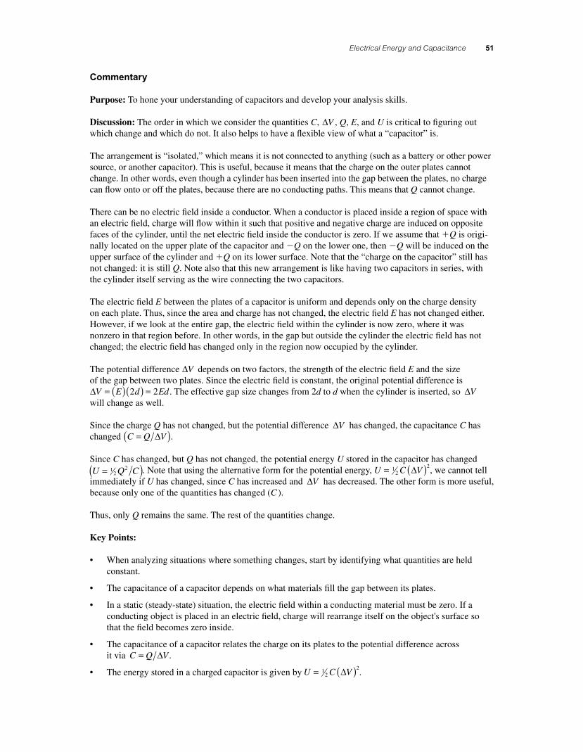
Two parallel conducting plates form a capacitor. With a metal cylinder of length half the plate separation inserted between the plates, it is connected to a battery with potential ∆V . The cylinder is now removed.
56157_16_ch16_p039-085.indd 5256157_16_ch16_p039-085.indd 52 3/18/08 1:23:26 PM3/18/08 1:23:26 PM
Electrical Energy and Capacitance 53
2d∆V
d
How many of the quantities C, ∆V , Q, E, and U change?
Input a number from 0 to 5, or choose (9) for “impossible to determine.”
Commentary
Purpose: To hone your understanding of capacitors and develop your analysis skills.
Discussion: The order in which we consider the various quantities C, ∆V , Q, E, and U matters; it’s easier to determine whether some change after others have been fi gured out.
If the battery remains connected, it will maintain a constant potential difference ∆V across the capacitor. (That’s what batteries do.) It will allow charge to fl ow to or from the plates as necessary, so Q is not necessarily constant.
What is the effect of the metal cylinder? It can have no electric fi eld within it, so positive charge will build up on one end and negative charge on the other. Effectively, this will be like having a capacitor whose separation distance is d (or, equivalently, two capacitors in series whose separation distances add up to d ). If the effective separation changes when the cylinder is removed, the capacitance C must change. (For a parallel-plate capacitor, C A d= ∈0 .) And if ∆V is constant but C changes, then Q must change according to C Q V= ∆ .
The electric fi eld within a capacitor is proportional to the charge density on the plates, so if Q changes, E must also. (We already know that E changes in the space formerly fi lled by the cylinder; now we know it changes in the rest of the capacitor, too.)
How about the stored energy U? Since U C V= ( )12
2∆ , that must change as well. So, C, Q, E, and U change, but ∆V does not. The best answer is therefore (4).
Key Points:
• When analyzing situations where something changes, start by identifying what quantities are held constant.
• The capacitance of a capacitor depends on what materials fi ll the gap between its plates.
• The capacitance of a capacitor relates the charge on its plates to the potential difference across it via C Q V= ∆ .
• The energy stored in a charged capacitor is given by U C V= ( )12
2∆ .
• The capacitance of a parallel plate capacitor with an empty gap is C A d= ∈0 .
56157_16_ch16_p039-085.indd 5356157_16_ch16_p039-085.indd 53 3/18/08 1:23:27 PM3/18/08 1:23:27 PM
54 Chapter 16
For Instructors Only
Because there are so many combinations in which 4 quantities change, students might select the right answer for the wrong reasons. Therefore, you should focus less on the “correctness” of the answer and more on exactly which quantities change.
Rather than discussing the correctness of the answers, use the distribution of student responses as a spring-board to launch a discussion of the various quantities and how one can reason whether each changes. In addition to having students explain why they believe some quantity changes, you can ask them whether their reasoning suggests the quantity will increase or decrease.
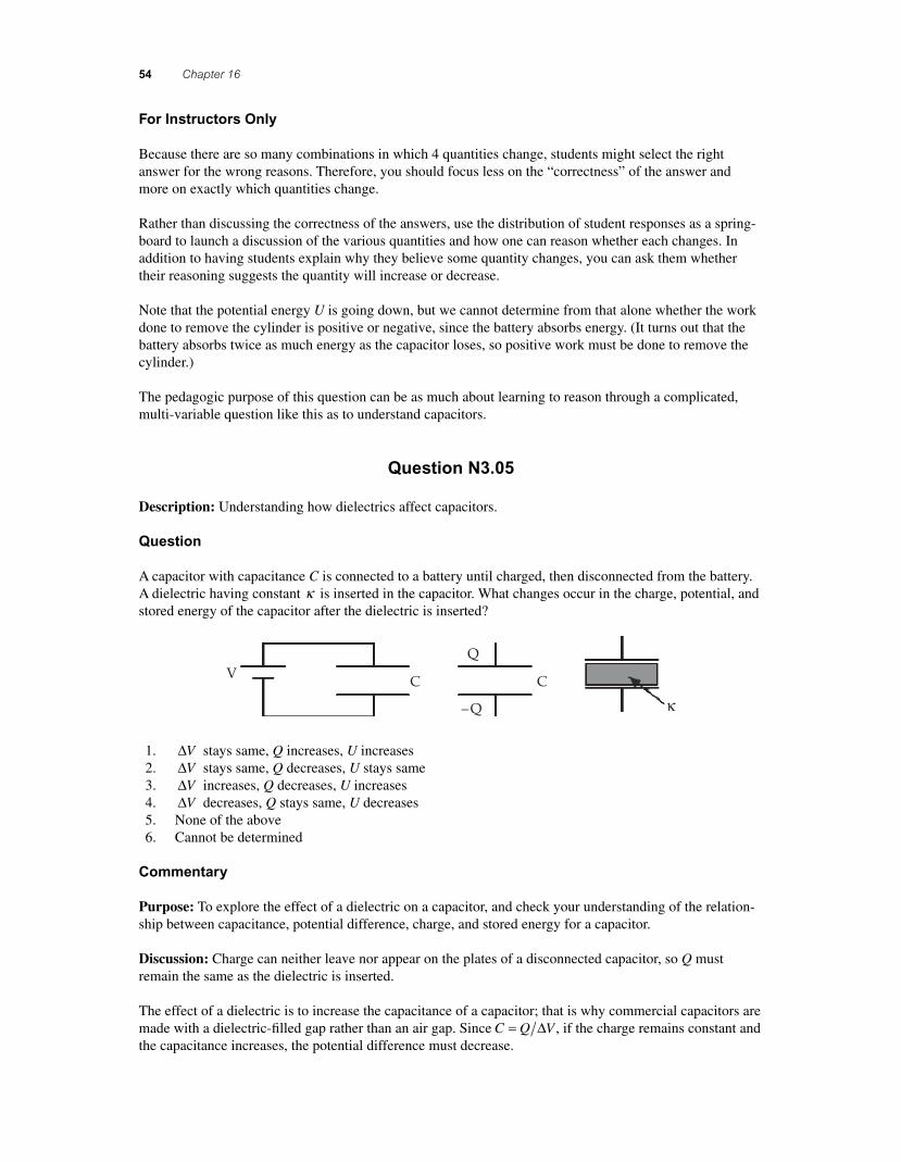
Note that the potential energy U is going down, but we cannot determine from that alone whether the work done to remove the cylinder is positive or negative, since the battery absorbs energy. (It turns out that the battery absorbs twice as much energy as the capacitor loses, so positive work must be done to remove the cylinder.)
The pedagogic purpose of this question can be as much about learning to reason through a complicated, multi-variable question like this as to understand capacitors.
Question N3.05
Description: Understanding how dielectrics affect capacitors.
Question
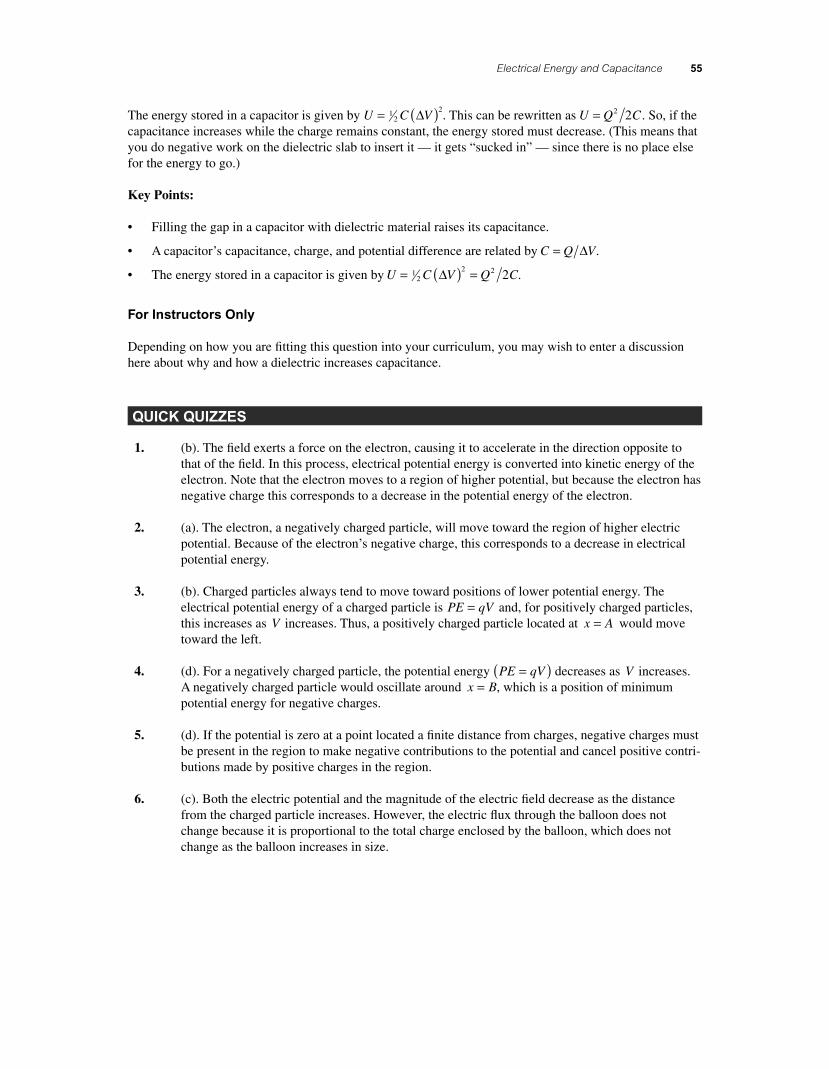
A capacitor with capacitance C is connected to a battery until charged, then disconnected from the battery. A dielectric having constant κ is inserted in the capacitor. What changes occur in the charge, potential, and stored energy of the capacitor after the dielectric is inserted?
V C C
Q
–Q κ
1. ∆V stays same, Q increases, U increases 2. ∆V stays same, Q decreases, U stays same 3. ∆V increases, Q decreases, U increases 4. ∆V decreases, Q stays same, U decreases 5. None of the above 6. Cannot be determined
Commentary
Purpose: To explore the effect of a dielectric on a capacitor, and check your understanding of the relation-ship between capacitance, potential difference, charge, and stored energy for a capacitor.
Discussion: Charge can neither leave nor appear on the plates of a disconnected capacitor, so Q must remain the same as the dielectric is inserted.
The effect of a dielectric is to increase the capacitance of a capacitor; that is why commercial capacitors are made with a dielectric-fi lled gap rather than an air gap. Since C Q V= ∆ , if the charge remains constant and the capacitance increases, the potential difference must decrease.
56157_16_ch16_p039-085.indd 5456157_16_ch16_p039-085.indd 54 3/18/08 1:23:28 PM3/18/08 1:23:28 PM
Electrical Energy and Capacitance 55
The energy stored in a capacitor is given by U C V= ( )12
2∆ . This can be rewritten as U Q C= 2 2 . So, if the capacitance increases while the charge remains constant, the energy stored must decrease. (This means that you do negative work on the dielectric slab to insert it — it gets “sucked in” — since there is no place else for the energy to go.)
Key Points:
• Filling the gap in a capacitor with dielectric material raises its capacitance.
• A capacitor’s capacitance, charge, and potential difference are related by C Q V= ∆ .
• The energy stored in a capacitor is given by U C V Q C= ( ) =12
2 2 2∆ .
For Instructors Only
Depending on how you are fi tting this question into your curriculum, you may wish to enter a discussion here about why and how a dielectric increases capacitance.
QUICK QUIZZES
1. (b). The fi eld exerts a force on the electron, causing it to accelerate in the direction opposite to that of the fi eld. In this process, electrical potential energy is converted into kinetic energy of the electron. Note that the electron moves to a region of higher potential, but because the electron has negative charge this corresponds to a decrease in the potential energy of the electron.
2. (a). The electron, a negatively charged particle, will move toward the region of higher electric potential. Because of the electron’s negative charge, this corresponds to a decrease in electrical potential energy.
3. (b). Charged particles always tend to move toward positions of lower potential energy. The electrical potential energy of a charged particle is PE qV= and, for positively charged particles, this increases as V increases. Thus, a positively charged particle located at x A= would move toward the left.
4. (d). For a negatively charged particle, the potential energy PE qV=( ) decreases as V increases. A negatively charged particle would oscillate around x B= , which is a position of minimum potential energy for negative charges.
5. (d). If the potential is zero at a point located a fi nite distance from charges, negative charges must be present in the region to make negative contributions to the potential and cancel positive contri-butions made by positive charges in the region.
6. (c). Both the electric potential and the magnitude of the electric fi eld decrease as the distance from the charged particle increases. However, the electric fl ux through the balloon does not change because it is proportional to the total charge enclosed by the balloon, which does not change as the balloon increases in size.
56157_16_ch16_p039-085.indd 5556157_16_ch16_p039-085.indd 55 3/18/08 1:23:28 PM3/18/08 1:23:28 PM
56 Chapter 16
7. (a). From the conservation of energy, the fi nal kinetic energy of either particle will be given by
KE KE PE PE qV qV q V V q Vf i i f i f f i= + −( ) = + − = − −( ) = − (0 ∆ ))
For the electron, q e V= − = + and V∆ 1 , giving KE ef = − −( ) +( ) = +1 1 V eV.
For the proton, q e V= + = − and V∆ 1 , so KE ef = − ( ) −( ) = +1 1 V eV, the same as that of the electron.
8. (c). The battery moves negative charge from one plate and puts it on the other. The fi rst plate is left with excess positive charge whose magnitude equals that of the negative charge moved to the other plate.
9. (a) C decreases. (b) Q stays the same. (c) E stays the same.
(d) ∆V increases. (e) The energy stored increases.
Because the capacitor is removed from the battery, charges on the plates have nowhere to go. Thus, the charge on the capacitor plates remains the same as the plates are pulled apart. Because
EQ A=
∈=
∈σ
0 0
, the electric fi eld is constant as the plates are separated. Because ∆V = Ed and E
does not change, ∆V increases as d increases. Because the same charge is stored at a higher poten-tial difference, the capacitance has decreased. Because Energy stored = Q C2 2 and Q stays the same while C decreases, the energy stored increases. The extra energy must have been transferred from somewhere, so work was done. This is consistent with the fact that the plates attract one another, and work must be done to pull them apart.
10. (a) C increases. (b) Q increases. (c) E stays the same.
(d) ∆V remains the same. (e) The energy stored increases.
The presence of a dielectric between the plates increases the capacitance by a factor equal to the dielectric constant. Since the battery holds the potential difference constant while the capaci-tance increases, the charge stored Q C V=( )∆ will increase. Because the potential difference and the distance between the plates are both constant, the electric fi eld E V d=( )∆ will stay the same. The battery maintains a constant potential difference. With ∆V constant while capacitance increases, the stored energy Energy stored = ( )( )1
22
C V∆ will increase.
11. (a). Increased random motions associated with an increase in temperature make it more diffi cult to maintain a high degree of polarization of the dielectric material. This has the effect of decreas-ing the dielectric constant of the material, and in turn, decreasing the capacitance of the capacitor.
ANSWERS TO MULTIPLE CHOICE QUESTIONS
1. The change in the potential energy of the proton is equal to the negative of the work done on it by the electric fi eld. Thus,
∆ ∆PE W qE xx= − = − ( ) = − + ×( )( )−1 6 10 850 2 519. . C N C mm J−( ) = − × −0 3 4 10 16.
and (b) is the correct choice for this question.
56157_16_ch16_p039-085.indd 5656157_16_ch16_p039-085.indd 56 3/18/08 1:23:29 PM3/18/08 1:23:29 PM
Electrical Energy and Capacitance 57
2. Because electric forces are conservative, the kinetic energy gained is equal to the decrease in electrical potential energy, or
KE PE q V= − = − ( ) = − −( ) + ×( ) = + ×Δ 1 1 0 10 1 0 104 4 e V . . eeV
so the correct choice is (a).
3. From conservation of energy, KE PE KE PEf f i i+ = + , or 12
2 12
2m m qV qVf i i fv v= + −
or
m s
v vf ii fq V V
m= +
−
= ×( ) +
2
5 2
2
6 20 102 2 1
( )
..660 10 1 50 4 00 10
6 63 10
19 3
2
×( ) −( ) ×⎡⎣ ⎤⎦×
−
−
C V. .
. 7753 78 10
kgm s= ×.
Thus, the correct answer is choice (b).
4. In a uniform electric fi eld, the change in electric potential is Δ ΔV E xx= − ( ), giving
EV
x
V V
x xx
f i
f i
= − = −−( )−( ) = −
−( )ΔΔ
190 120
5 0
V V
. mm mV m N C
−( ) = − = −3 0
35 35.
and it is seen that the correct choice is (d).
5. With the given specifi cations, the capacitance of this parallel plate capacitor will be
CA
d= ∈ =
×( ) × ⋅( )−κ 0
2 121 00 10 8 85 10 1 0. . . C N m cm2 2 22 2
2 m
m
cm
( )×
⎛⎝⎜
⎞⎠⎟
= ×
−
−
1 0 10
1
10
8 85 10
3 4
11
.
. FF F pF= × =−88 5 10 88 512. .
and the correct choice is (a).
6. The total potential at a point due to a set of point charges qi is V kq ri ii
= ∑ , where ri is the
distance from the point of interest to the location of the charge qi . Note that in this case, the point at the center of the circle is equidistant from the 4 point charges located on the rim of the circle. Note also that q q q2 3 4 1 5 1 0 0 5 0+ + = + − −( ) =. . . Cμ , so we have
Vk q
r
k q
r
k q
r
k q
r
k
rq q qe e e e e
center = + + + = + +1 2 3 41 2 3 ++( ) = +( ) = = = ×q
k
rq
k q
rVe e
4 11
140 4 5 10. V
or the total potential at the center of the circle is just that due to the fi rst charge alone, and the cor-rect answer is choice (b).
7. In a series combination of capacitors, the equivalent capacitance is always less than any individual capacitance in the combination, meaning that choice (a) is false. Also, for a series combination of capacitors, the magnitude of the charge is the same on all plates of capacitors in the combina-tion, making both choices (d) and (e) false. The potential difference across the capacitance Ci is ΔV Q Ci i= , where Q is the common charge on each capacitor in the combination. Thus, the larg-est potential difference (voltage) appears across the capacitor with the least capacitance, making choice (b) the correct answer.
8. Keeping the capacitor connected to the battery means that the potential difference between the plates is kept at a constant value equal to the voltage of the battery. Since the capacitance of a parallel plate capacitor is C A d= ∈κ 0 , doubling the plate separation d, while holding other characteristics of the capacitor constant, means the capacitance will be decreased by a factor of 2.
56157_16_ch16_p039-085.indd 5756157_16_ch16_p039-085.indd 57 3/18/08 11:28:10 PM3/18/08 11:28:10 PM
58 Chapter 16
The energy stored in a capacitor may be expressed as U C V= ( )12
2Δ , so when the potential dif-ference ΔV is held constant while the capacitance is decreased by a factor of 2, the stored energy decreases by a factor of 2, making (c) the correct choice for this question.
9. When the battery is disconnected, there is no longer a path for charges to use in moving onto or off of the plates of the capacitor. This means that the charge Q is constant. The capacitance of a parallel plate capacitor is C A d= ∈κ 0 and the dielectric constant is κ ≈ 1 when the capacitor is air fi lled. When a dielectric with dielectric constant κ = 2 is inserted between the plates, the capacitance is doubled C Cf i=( )2 . Thus, with Q constant, the potential difference between the plates, ΔV Q C= , is decreased by a factor of 2, meaning that choice (a) is a true statement. The electric fi eld between the plates of a parallel plate capacitor is E V d= Δ and decreases when ΔV decreases, making choice (e) false and leaving (a) as the only correct choice for this question.
10. Once the capacitor is disconnected from the battery, there is no path for charges to move onto or off of the plates, so the charges on the plates are constant, and choice (e) can be eliminated. The capacitance of a parallel plate capacitor is C A d= ∈κ 0 , so the capacitance decreases when the plate separation d is increased. With Q constant and C decreasing, the energy stored in the capaci-tor, U Q C= 2 2 increases, making choice (a) false and choice (b) true. The potential difference between the plates, ΔV Q C Q d A= = ⋅ ∈κ 0 , increases and the electric fi eld between the plates, E V d Q A= = ∈Δ κ 0 , is constant. This means that both choices (c) and (d) are false and leaves choice (b) as the only correct response.
11. Capacitances connected in parallel all have the same potential difference across them and the equivalent capacitance, C C C Ceq = + + +1 2 3 L, is larger than the capacitance of any one of the capacitors in the combination. Thus, choice (c) is a true statement. The charge on a capacitor is Q C V= ( )Δ , so with ΔV constant, but the capacitances different, the capacitors all store different charges that are proportional to the capacitances, making choices (a), (b), (d), and (e) all false. Therefore, (c) is the only correct answer.
12. For a series combination of capacitors, the magnitude of the charge is the same on all plates of capacitors in the combination. Also, the equivalent capacitance is always less than any individual capacitance in the combination. Therefore, choice (a) is true while choices (b) and (c) are both false. The potential difference across a capacitor is ΔV Q C= , so with Q constant, capacitors having different capacitances will have different potential differences across them, with the largest potential difference being across the capacitor with the smallest capacitance. This means that choice (d) is false and choice (e) is true. Thus, both choices (a) and (e) are true statements.
ANSWERS TO EVEN NUMBERED CONCEPTUAL QUESTIONS
2. Changing the area will change the capacitance and maximum charge but not the maximum volt-age. The question does not allow you to increase the plate separation. You can increase the maxi-mum operating voltage by inserting a material with higher dielectric strength between the plates.
4. Electric potential V is a measure of the potential energy per unit charge. Electrical potential energy, PE � QV, gives the energy of the total charge Q.
6. A sharp point on a charged conductor would produce a large electric fi eld in the region near the point. An electric discharge could most easily take place at the point.
56157_16_ch16_p039-085.indd 5856157_16_ch16_p039-085.indd 58 3/18/08 10:30:50 PM3/18/08 10:30:50 PM
Electrical Energy and Capacitance 59
8. There are eight different combinations that use all three capacitors in the circuit. These combina-tions and their equivalent capacitances are:
All three capacitors in series - CC C Ceq = + +
⎛⎝⎜
⎞⎠⎟
−1 1 1
1 2 3
1
All three capacitors in parallel - C C C Ceq = + +1 2 3
One capacitor in series with a parallel combination of the other two:
CC C Ceq =
++
⎛⎝⎜
⎞⎠⎟
−1 1
1 2 3
1
, CC C Ceq =
++
⎛⎝⎜
⎞⎠⎟
−1 1
3 1 2
1
, CC C Ceq =
++
⎛⎝⎜
⎞⎠⎟
−1 1
2 3 1
1
One capacitor in parallel with a series combination of the other two:
CC C
C CCeq =
+⎛⎝⎜
⎞⎠⎟
+1 2
1 23,
CC C
C CCeq =
+⎛⎝⎜
⎞⎠⎟
+3 1
3 12,
CC C
C CCeq =
+⎛⎝⎜
⎞⎠⎟
+2 3
2 31
10. Nothing happens to the charge if the wires are disconnected. If the wires are connected to each other, the charge rapidly recombines, leaving the capacitor uncharged.
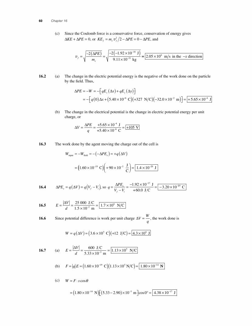
12. All connections of capacitors are not simple combinations of series and parallel circuits. As an example of such a complex circuit, consider the network of fi ve capacitors C
1, C
2, C
3, C
4, and C
5
shown below.
This combination cannot be reduced to a simple equivalent by the techniques of combining series and parallel capacitors.
14. The material of the dielectric may be able to withstand a larger electric fi eld than air can withstand before breaking down to pass a spark between the capacitor plates.
PROBLEM SOLUTIONS
16.1 (a) Because the electron has a negative charge, it experiences a force in the direction opposite to the fi eld and, when released from rest, will move in the negative x direction. The work done on the electron by the fi eld is
W F x qE xx x= ( ) = ( ) = − ×( )( ) −−Δ Δ 1 60 10 375 319. . C N C 220 10 1 92 102 18×( ) = ×− − m J.
(b) The change in the electric potential energy is the negative of the work done on the particle by the fi eld. Thus,
ΔPE W= − = − × −1 92 10 18. J
continued on next page
56157_16_ch16_p039-085.indd 5956157_16_ch16_p039-085.indd 59 3/18/08 10:31:59 PM3/18/08 10:31:59 PM
60 Chapter 16
(c) Since the Coulomb force is a conservative force, conservation of energy gives
∆ ∆KE PE+ = 0, or KE m PE PEf e f= − = −v2 2 0∆ ∆ , and
v f
e
PE
m=
− ( ) =− − ×( )
×
−
−
2 2 1 92 10
9 11 10
18
31
∆ .
.
J
kg== × −2 05 106. m s in the directionx
16.2 (a) The change in the electric potential energy is the negative of the work done on the particle by the fi eld. Thus,
∆ ∆ ∆
∆
PE W qE x qE y
q x
x y= − = − ( ) + ( )⎡⎣ ⎤⎦
= − ( ) + ×0 5 40 10. −− −( ) +( ) − ×( )⎡⎣ ⎤⎦ = + ×6 2327 32 0 10 5 65 10 C N C m. . −−4 J
(b) The change in the electrical potential is the change in electric potential energy per unit charge, or
∆ ∆
VPE
q= = + ×
×= +
−
−
5 65 10
10105
4. J
+5.40 C V6
16.3 The work done by the agent moving the charge out of the cell is
W W PE q Veinput field
C
= − = − −( ) = + ( )
= × −
∆ ∆
1 60 10 19.(( ) + ×⎛⎝⎜
⎞⎠⎟ = ×− −90 10 1 4 103 20
J
C J.
16.4 ∆ ∆PE q V q V Ve f i= ( ) = −( ), so qPE
V Ve
f i
=−
= − × = − ×−
−∆ 1 92 103 20 10
17..
J
+60.0 J C119 C
16.5 EV
d= =
×= ×−
∆ 25 000
1 5 101 7 102
6 J C
m N C
..
16.6 Since potential difference is work per unit charge ∆VW
q= , the work done is
W q V= ( ) = ×( ) +( ) = ×∆ 3 6 10 12 4 3 105 6. . C J C J
16.7 (a) EV
d= =
×= ×−
∆ 600
5 33 101 13 103
5 J C
m N C
..
(b) F q E= = ×( ) ×( ) = ×− −1 60 10 1 13 10 1 80 1019 5 14. . . C N C NN
(c) W F s= ⋅
= ×( ) −( ) ×⎡− −
cos
. . .
θ
1 80 10 5 33 2 90 1014 3 N m⎣⎣ ⎤⎦ = × −cos .0 4 38 10 17° J
56157_16_ch16_p039-085.indd 6056157_16_ch16_p039-085.indd 60 3/18/08 1:23:33 PM3/18/08 1:23:33 PM
Electrical Energy and Capacitance 61
16.8 (a) Using conservation of energy, Δ ΔKE PE+ = 0, with KE f = 0 since the particle is “stopped,” we have
Δ ΔPE KE m i= − = − −⎛⎝⎜
⎞⎠⎟ = + ×( −0
1
2
1
29 11 102 31
e kgv . )) ×( ) = + × −2 85 10 3 70 107 2 16. .m s J
The required stopping potential is then
Δ ΔV
PE
q= = + ×
− ×= − ×
−
−
3 70 10
1 60 102 31 10
16
19
.
..
J
C33 2 31 V kV= − .
(b) Being more massive than electrons, protons traveling at the same initial speed will have
more initial kinetic energy and require a greater magnitude stopping potentiial .
(c) Since Δ Δ ΔV
PE
q
KE
q
m
qstopping = = − = − v2 2, the ratio of the stopping potential for a proton to
that for an electron having the same initial speed is
ΔΔ
V
V
m e
m em mi
i
p
e
p
ep e=
− +− −
= −v
v
2
2
2
2
( )
( )
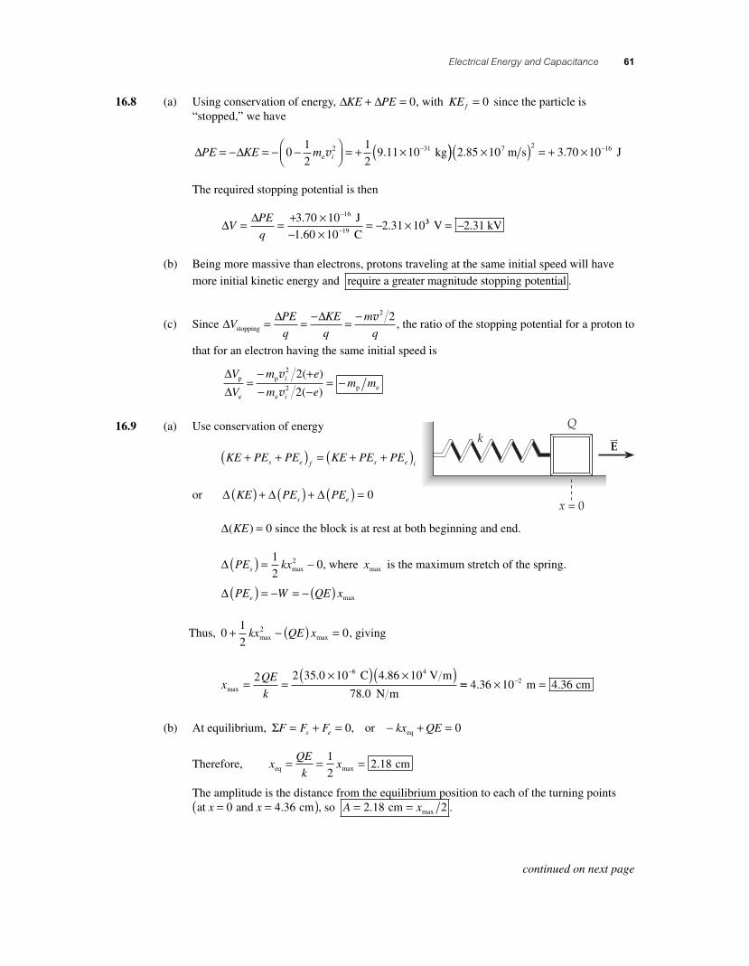
16.9 (a) Use conservation of energy
KE PE PE KE PE PEs e f s e i+ +( ) = + +( )
or Δ Δ ΔKE PE PEs e( ) + ( ) + ( ) = 0
Δ( )KE = 0 since the block is at rest at both beginning and end.
Δ PE kxs( ) = −1
202
max , where xmax is the maximum stretch of the spring.
Δ PE W QE xe( ) = − = − ( ) max
Thus, 01
202+ − ( ) =kx QE xmax max , giving
x
QE
kmax
C V m
78.0 N m= =
×( ) ×( )−2 2 35 0 10 4 86 106 4. .
== × =−4 36 10 4 362. .m cm
(b) At equilibrium, ΣF F F kx QEs e= + = − + =0 0, or eq
Therefore, xQE
kxeq cm= = =1
22 18max .
The amplitude is the distance from the equilibrium position to each of the turning pointsat and cmx x= =( )0 4 36. , so A x= =2 18 2. max cm .
continued on next page
56157_16_ch16_p039-085.indd 6156157_16_ch16_p039-085.indd 61 3/19/08 1:54:16 AM3/19/08 1:54:16 AM
62 Chapter 16
(c) From conservation of energy, Δ Δ Δ ΔKE PE PE kx Q Vs e( ) + ( ) + ( ) = + + ( ) =01
202
max . Since
x Amax = 2 , this gives
ΔVkx
Q
k A
Q= − = −
( )max2 2
2
2
2 or ΔV
kA
Q= − 2 2
16.10 Using Δy t a ty y= +v021
2 for the full fl ight gives
01
202= +v y yt a t , or a
tyy=
−2 0v
Then, using v vy y ya y202 2= + ( )Δ for the upward part of the fl ight gives
Δya t
ty
y
y
y
y( ) =−
=−
−( ) = =max
0
2 2 2 4
20 102
02
0
0v v
v
v . m s s
4 m
( )( )=
4 1020 6
..
From Newton’s second law, aF
m
mg qE
mg
qE
myy= = − − = − +⎛
⎝⎜⎞⎠⎟
Σ. Equating this to the earlier
result gives a gqE
m tyy= − +⎛
⎝⎜⎞⎠⎟ =
−2 0v, so the electric fi eld strength is
E
m
q tgy=
⎛⎝⎜
⎞⎠⎟
−⎡⎣⎢
⎤⎦⎥ =
×⎛
−
2 2 00
5 00 100
6
v .
.
kg
C⎝⎝⎜⎞⎠⎟
( )−
⎡
⎣⎢
⎤
⎦⎥ = ×
2 20 1
4 109 80 1 95
.
.. .
m s
s m s2 1103 N C
Thus, Δ ΔV y E( ) = ( ) = ( ) ×( ) = ×max max m N C20 6 1 95 10 4 023. . . 110 40 24 V kV= .
16.11 (a) Vk q
rAe
A
= =× ⋅( ) − ×( )−8 99 10 1 60 10
0
9 2 19. .
.
N m C C2
2250 105 75 10
27
×= − ×−
−
mV.
(b) Vk q
rBe
B
= =× ⋅( ) − ×( )−8 99 10 1 60 109 19. .N m C C
0.
2 2
7750 mV
2×= − ×−
−
101 92 10 7.
ΔV V VB A= − = − × − − ×( ) = + ×− −1 92 10 5 75 10 3 837 7. . .V V 110 7− V
(c) The original electron will be repelled by the negatively charged particle which suddenly appears at point A. Unless the electron is fi xed in place, it will move in the opposite direc-tion, away from points A and B, thereby lowering the potential difference between these points.
16.12 (a) At the origin, the total potential is
Vkq
r
kq
rorigin
2 2N m C
= +
= × ⋅( ) ×
1
1
2
2
98 99 104 50 1
.. 00
10
2 24 10
10
6 6−
−
−
−×+
− ×( )×
C
1.25 m
C
1.80 m2 2
.⎡⎡
⎣⎢⎢
⎤
⎦⎥⎥
= ×2 12 106. V
continued on next page
56157_16_ch16_p039-085.indd 6256157_16_ch16_p039-085.indd 62 3/19/08 2:15:55 AM3/19/08 2:15:55 AM
Electrical Energy and Capacitance 63
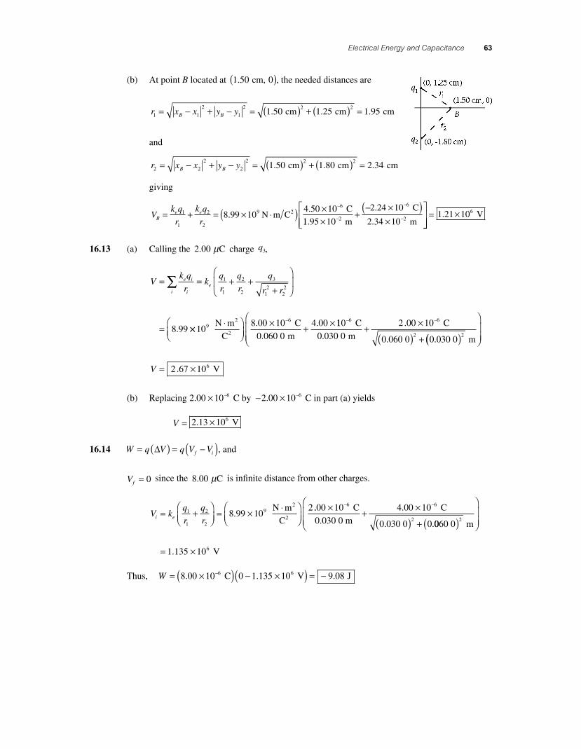
(b) At point B located at 1 50 0. cm, ( ), the needed distances are
r x x y yB B1 1
2
1
2 2 21 50 1 25 1 95= − + − = ( ) + ( ) =. . . cm cm cm
and
r x x y yB B2 2
2
2
2 2 21 50 1 80 2 34= − + − = ( ) + ( ) =. . . cm cm cm
giving
Vk q
r
k q
rBe e= + = × ⋅( ) × −
1
1
2
2
96
8 99 104 50 10
..
N m CC2
11.95 m
C
m2×+
− ×( )×
⎡
⎣⎢⎢
⎤−
−
−10
2 24 10
2 34 10
6
2
.
. ⎦⎦⎥⎥
= ×1 21 106. V
16.13 (a) Calling the 2 00. Cμ charge q3,
Vk q
rk
q
r
q
r
q
r re i
iie= = + +
+
⎛
⎝⎜
⎞
⎠⎟
=
∑ 1
1
2
2
3
12
22
8 99. ×× ⋅⎛⎝⎜
⎞⎠⎟
× + ×−
108 00 10
0 060 0
4 0096
N m
C
C
m
2
2
.
.
. 110
0 030 0
2 00 10
0 060 0 0 030 0
6 6
2
− −
+ ×
( ) +
C
m
C
.
.
. .(( )
⎛
⎝⎜⎜
⎞
⎠⎟⎟
= ×
2
62 67 10
m
VV .
(b) Replacing 2 00 10 2 00 106 6. .× − ×− − C by C in part (a) yields
V = ×2 13 106. V
16.14 W q V q V Vf i= ( ) = −( )Δ , and
Vf = 0 since the 8 00. Cμ is infi nite distance from other charges.
V kq
r
q
ri e= +⎛⎝⎜
⎞⎠⎟
= × ⋅⎛⎝⎜
⎞⎠⎟
1
1
2
2
98 99 102
. N m
C
2
2
.. .00 10 4 00 106 6
2
× + ×
( ) +
− − C
0.030 0 m
C
0.030 0 0.0060 0 m
V
( )
⎛
⎝⎜⎜
⎞
⎠⎟⎟
= ×
2
61 135 10.
Thus, W = ×( ) − ×( ) = −−8 00 10 0 1 135 10 9 086 6. . . C V J
56157_16_ch16_p039-085.indd 6356157_16_ch16_p039-085.indd 63 3/19/08 2:16:33 AM3/19/08 2:16:33 AM
64 Chapter 16
16.15 (a) Vk q
re i
ii
=
= × ⋅⎛⎝⎜
⎞⎠⎟
×
∑
−
8 99 105 00 109
9
..
N m
C
C2
2 00.175 m
C
0.175 m V− ×⎛
⎝⎜⎞⎠⎟
=−3 00 10
1039.
(b) PEk q q
re i=
= × ⋅⎛⎝⎜
⎞⎠⎟
× −
2
12
99
8 99 105 00 10
..
N m
C
2
2
C C
0.350 m J
( ) − ×( )= − ×
−−3 00 10
3 85 109
7.
.
The negative sign means that positive work must be done to separate the charges (that is,
bring them up to a state of zero potential energy).
16.16 The potential at distance r = 0 300. m from a charge Q = + × −9 00 10 9. C is
V
k Q
re= =
× ⋅( ) ×( )−8 99 10 9 00 109 9. . N m C C
0.300
2 2
mm V= +270
Thus, the work required to carry a charge q = × −3 00 10 9. C from infi nity to this location is
W qV= = ×( ) +( ) = ×− −3 00 10 270 8 09 109 7. . C V J
16.17 The Pythagorean theorem gives the distance from the midpoint of the base to the charge at the apex of the triangle as
r3
2 2 24 00 1 00 15 15 10= ( ) − ( ) = = × −. . cm cm cm m
Then, the potential at the midpoint of the base is V k q re i ii
= ∑ , or
V = × ⋅⎛⎝⎜
⎞⎠⎟
− ×( )−
8 99 107 00 10
99
..
N m
C
C
0.010 0
2
2 m
C
0.010 0 m
C+
− ×( )+
+ ×( )− −7 00 10 7 00 10
15
9 9. .
××
⎛
⎝⎜
⎞
⎠⎟
= − × = −
−10
1 10 10 11 0
2
4
m
V kV. .
56157_16_ch16_p039-085.indd 6456157_16_ch16_p039-085.indd 64 3/18/08 1:23:36 PM3/18/08 1:23:36 PM
Electrical Energy and Capacitance 65
16.18 Outside the spherical charge distribution, the potential is the same as for a point charge at the center of the sphere,
V k Q re= , where Q = × −1 00 10 9. C
Thus, ∆ ∆PE q V ek Qr re e
f i
( ) = ( ) = − −⎛
⎝⎜⎞
⎠⎟1 1
and from conservation of energy, ∆ ∆KE PEe( ) = − ( ) ,
or 1
20
1 12m ek Qr re e
f i
v − = − − −⎛
⎝⎜⎞
⎠⎟⎡
⎣⎢⎢
⎤
⎦⎥⎥. This gives v = −
⎛
⎝⎜⎞
⎠⎟2 1 1k Qe
m r re
e f i
, or
v =× ⋅⎛
⎝⎜⎞⎠⎟
×( ) ×−2 8 99 10 1 00 10 1 60 19 9. . . N m
C C
2
2 00
9 11 10
1
0 020 0
1
0 030 0
19
31
−
−
( )×
−⎛⎝
C
kg m m. . .⎜⎜⎞⎠⎟
v = ×7 25 106. m s
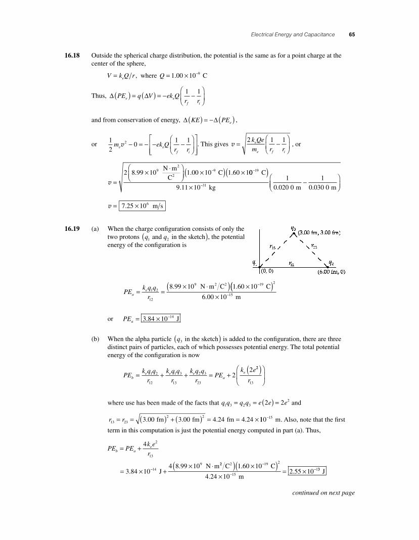
16.19 (a) When the charge confi guration consists of only the two protons q q1 2 and in the sketch( ), the potential energy of the confi guration is
PEk q q
rae= =
× ⋅( ) × −1 2
12
9 198 99 10 1 60 10. . N m C C2 2 (( )× −
2
156 00 10. m
or PEa = × −3 84 10 14. J
(b) When the alpha particle q3 in the sketch( ) is added to the confi guration, there are three distinct pairs of particles, each of which possesses potential energy. The total potential energy of the confi guration is now
PEk q q
r
k q q
r
k q q
rPE
k eb
e e ea
e= + + = +1 2
12
1 3
13
2 3
23
22 22
13
( )⎛
⎝⎜
⎞
⎠⎟r
where use has been made of the facts that q q q q e e e1 3 2 322 2= = ( ) = and
r r13 23
2 23 00 3 00 4 24 4 24= = ( ) + ( ) = = ×. . . . fm fm fm 110 15− m. Also, note that the fi rst
term in this computation is just the potential energy computed in part (a). Thus,
PE PEk e
rb ae= +
= × +× ⋅−
4
3 84 104 8 99 10
2
13
149
..
J N m22 2C C
m
( ) ×( )×
= ×−
−−1 60 10
4 24 102 55 10
19 2
151
.
.. 33 J
continued on next page
56157_16_ch16_p039-085.indd 6556157_16_ch16_p039-085.indd 65 3/18/08 1:23:37 PM3/18/08 1:23:37 PM
66 Chapter 16
(c) If we start with the three-particle system of part (b) and allow the alpha particle to escape to infi nity [thereby returning us to the two-particle system of part (a)], the change in electric potential energy will be
∆PE PE PEa b= − = × − × = −− −3 84 10 2 55 10 2 1714 13. . . J J ×× −10 13 J
(d) Conservation of energy, ∆ ∆KE PE+ = 0, gives the speed of the alpha particle at infi nity in the situation of part (c) as m PEα αv2 2 0− = −∆ , or
vα
α
=− ( ) =
− − ×( )×
−
−
2 2 2 17 10
6 64 10
13
27
∆PE
m
.
.
J
kg== ×8 08 106. m s
(e) When, starting with the three-particle system, the two protons are both allowed to escape to infi nity, there will be no remaining pairs of particles and hence no remaining potential energy. Thus, ∆PE PE PEb b= − = −0 , and conservation of energy gives the change in kinetic energy as ∆ ∆KE PE PEb= − = + . Since the protons are identical particles, this increase in kinetic energy is split equally between them giving
KE m PEp p bproton = = ( )1
2
1
22v
or vpb
p
PE
m= = ×
×= ×
−
−
2 55 10
101 24 10
137.
. J
1.67 kg27 m s
16.20 (a) If a proton and an alpha particle, initially at rest 4.00 fm apart, are released and allowed to recede to infi nity, the fi nal speeds of the two particles will differ because of the difference in the masses of the particles. Thus, attempting to solve for the fi nal speeds by use of conser-vation of energy alone leads to a situation of having one equation with two unknowns , and does not permit a solution.
(b) In the situation described in part (a) above, one can obtain a second equation with the two unknown fi nal speeds by using conservation of linear momentum . Then, one would have two equations which could be solved simultaneously both unknowns.
continued on next page
56157_16_ch16_p039-085.indd 6656157_16_ch16_p039-085.indd 66 3/18/08 1:23:39 PM3/18/08 1:23:39 PM
Electrical Energy and Capacitance 67
(c) From conservation of energy: 1
2
1
20 02 2m m
k q q
rp pe p
iα α
αv v+⎛⎝⎜
⎞⎠⎟ −⎡
⎣⎢⎤⎦⎥
+ −⎡
⎣⎢
⎤⎤
⎦⎥ = 0
or m mk q q
rp pe p
iα α
αv v2 292 2 8 99 10 3 2
+ = =× ⋅( ). . N m C2 2 00 10 1 60 10
4 00 10
19 19
15
×( ) ×( )×
− −
−
C C
m
.
.
yielding m mp pα αv v2 2 132 30 10+ = × −. J [1]
From conservation of linear momentum,
m mp pα αv v+ = 0 or v vαα
=⎛⎝⎜
⎞⎠⎟
m
mp
p [2]
Substituting Equation [2] into Equation [1] gives
mm
mmp
p p pαα
⎛⎝⎜
⎞⎠⎟
+ = × −2
2 2 132 30 10v v . J or m
mmp
p pα
+⎛⎝⎜
⎞⎠⎟
= × −1 2 30 102 13v . J
and
vp
p pm m m= ×
+( ) = ××
− −2 30 10
1
2 30 1013 13. . J J
1.67α 110 10 101 05 10− − −×( ) ×( ) = ×
27 27 276.64 +1 1.67 kg. 77 m s
Then, Equation [2] gives the fi nal speed of the alpha particle as
v vαα
=⎛⎝⎜
⎞⎠⎟
= ××
⎛ −
−
m
mp
p
1 67 10
6 64 10
27
27
.
.
kg
kg⎝⎝⎜⎞⎠⎟
×( ) = ×1 05 10 2 64 107 6. . m s m s
16.21 Vk Q
re= so
r
k Q
V Ve= =
× ⋅( ) ×( )=
−8 99 10 8 00 10 71 99 9. . . N m C C2 2
V m⋅V
For V = 100 V, 50.0 V, and 25.0 V, r = 0 719. m, 1.44 m, and 2 .88 m
The radii are inversely proportional to the potential.
16.22 By defi nition, the work required to move a charge from one point to any other point on an equi-potential surface is zero. From the defi nition of work, W F s= ( ) ⋅cosθ , the work is zero only if s = 0 or F cosθ = 0. The displacement s cannot be assumed to be zero in all cases. Thus, one must require that F cosθ = 0. The force F is given by F qE= and neither the charge q nor the fi eld strength E can be assumed to be zero in all cases. Therefore, the only way the work can be zero in all cases is if cosθ = 0. But if cosθ = 0, then θ = °90 or the force (and hence the electric fi eld) must be perpendicular to the displacement s (which is tangent to the surface). That is, the fi eld must be perpendicular to the equipotential surface at all points on that surface.
56157_16_ch16_p039-085.indd 6756157_16_ch16_p039-085.indd 67 3/18/08 1:23:39 PM3/18/08 1:23:39 PM
68 Chapter 16
16.23 From conservation of energy, KE PE KE PEe f e i+( ) = +( ) , which gives
01
202+ = +k Qq
rme
fiα v or r
k Qq
m
k e e
mfe
i
e
i
= =( )( )2 2 79 2
2 2α αv v
rf =× ⋅⎛
⎝⎜⎞⎠⎟
( ) ×( −2 8 99 10 158 1 60 109 19. . N m
C C
2
2 ))×( ) ×( )
= ×−
−
2
27 7 214
6 64 10 2 00 102 74 10
. ..
kg m s m
16.24 (a) The distance from any one of the corners of the square to the point at the center is one half the length of the diagonal of the square, or
rdiagonal a a a a= = + = =
2 2
2
2 2
2 2
Since the charges have equal magnitudes and are all the same distance from the center of the square, they make equal contributions to the total potential. Thus,
V Vk Q
r
k Q
ak
Q
ae e
etotal singlecharge
= = = =4 4 42
4 2
(b) The work required to carry charge q from infi nity to the point at the center of the square is equal to the increase in the electric potential energy of the charge, or
W PE PE qV q kQ
ake e= − = − = ⎛
⎝⎜⎞⎠⎟ =∞center total 0 4 2 4 2
qqQ
a
16.25 (a) CA
d= ∈ = ×
⋅⎛⎝⎜
⎞⎠⎟
×( )−0
126
8 85 101 0 10
..
C
N m
m
8
2
2
2
000 m F( ) = × −1 1 10 8.
(b) Q C V C E dmax max max
F
= ( ) = ( )
= ×( ) ×−
∆
1 11 10 3 0 108 6. . N C m C( )( ) =800 27
16.26 (a) CQ
V= = =
∆27 0
3 00.
. C
9.00 V F
µ µ
(b) Q C V= ( ) = ( )( ) =∆ 3 00 12 0 36 0. . . F V Cµ µ
16.27 (a) The capacitance of this air fi lled dielectric constant, κ =( )1 00. parallel plate capacitor is
Ck A
d= ∈ =
( ) × ⋅( ) ×− −0
12 41 00 8 85 10 2 30 10. . . C N m 2 2 mm
m F pF
2( )×
= × =−−
1 50 101 36 10 1 363
12
.. .
continued on next page
56157_16_ch16_p039-085.indd 6856157_16_ch16_p039-085.indd 68 3/18/08 1:23:40 PM3/18/08 1:23:40 PM
Electrical Energy and Capacitance 69
(b) Q C V= ( ) = ×( )( ) = ×− −Δ 1 36 10 12 0 1 63 1012 11. . . F V C == × =−16 3 10 16 312. . C pC
(c) EV
d= =
×= × = ×−
Δ 12 0
108 00 10 8 00 103.. .
V
1.50 m V m3
33 N C
16.28 (a) Q C V= ( ) = ×( )( ) = × =− −Δ 4 00 10 12 0 48 0 10 46 6. . . F V C 88 0. Cμ
(b) Q C V= ( ) = ×( )( ) = × =− −Δ 4 00 10 1 50 6 00 10 66 6. . . F V C ..00 Cμ
16.29 (a) EV
d= =
×= × =−
Δ 20 0
101 11 10 11 14.. .
V
1.80 mV m kV m3 directed toward the negative plate
(b) CA
d= ∈ =
× ⋅( ) ×( )− −0
12 48 85 10 7 60 10. . C N m m
1.8
2 2 2
00 10 m3× −
= × =−3 74 10 3 7412. . F pF
(c) Q C V= ( ) = ×( )( ) = ×− −Δ 3 74 10 20 0 7 47 1012 11. . . F V C == 74 7. pC on one plate and
−74 7. pC on the other plate.
16.30 CA
d= ∈0 , so
dA
C= ∈ =
× ⋅( ) ×( )− −0
12 128 85 10 21 0 10. . C N m m
60
2 2 2
..0 10 Fm15×
= ×−−3 10 10 9.
d = ×( )⎛
⎝⎜⎞⎠⎟
=−−3 10 10
131 09
1. .mÅ
10 mÅ0
16.31 (a) Assuming the capacitor is air-fi lled κ =( )1 , the capacitance is
CA
d= ∈ =
× ⋅( )( )×
−0
128 85 10 0 200
3 00 10
. .
.
C N m m2 2 2
−−−= ×3105 90 10
m F.
(b) Q C V= ( ) = ×( )( ) = ×− −Δ 5 90 10 6 00 3 54 1010 9. . . F V C
(c) EV
d= =
×= × = ×−
Δ 6 00
102 00 10 2 00 103.. .
V
3.00 m V m3
33 N C
(d) σ = = × = ×−
−Q
A
3 54 101 77 10
98.
. C
0.200 m C m2
2
(e) Increasing the distance separating the plates decreases the capacitance, the charge stored, and the electric fi eld strength between the plates. This means that all of the
previous answers will be decreased .
56157_16_ch16_p039-085.indd 6956157_16_ch16_p039-085.indd 69 3/19/08 1:56:18 AM3/19/08 1:56:18 AM
70 Chapter 16
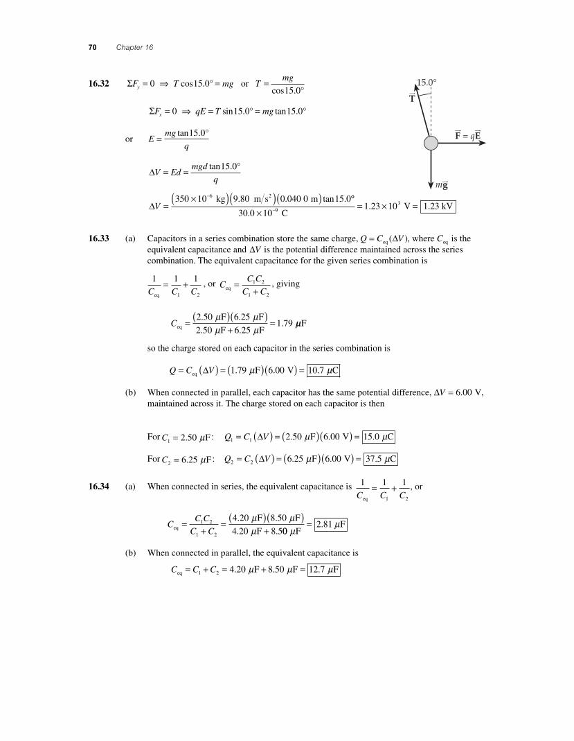
16.32 ΣF T mg Tmg
y = ⇒ = =0 15 015 0
or cos .cos .
°°
ΣF qE T mgx = ⇒ = =0 15 0 15 0 sin . tan .° °
or Emg
q= tan .15 0°
ΔV Edmgd
q= = tan .15 0°
ΔV =×( )( )( )−350 10 9 80 0 040 0 15 06 kg m s m2. . tan . °°
30 0 101 23 10 1 239
3
.. .
×= × =− C
V kV
16.33 (a) Capacitors in a series combination store the same charge, Q C V= eq ( )Δ , where Ceq is the equivalent capacitance and ΔV is the potential difference maintained across the series combination. The equivalent capacitance for the given series combination is
1 1 1
1 2C C Ceq
= + , or CC C
C Ceq =+1 2
1 2
, giving
Ceq
F F
F F = ( )( )
+=
2 50 6 25
2 50 6 251 79
. .
. ..
μ μμ μ
μμF
so the charge stored on each capacitor in the series combination is
Q C V= ( ) = ( )( ) =eq F V CΔ 1 79 6 00 10 7. . .μ μ
(b) When connected in parallel, each capacitor has the same potential difference, ΔV = 6 00. V, maintained across it. The charge stored on each capacitor is then
For C1 2 50= . Fμ : Q C V1 1 2 50 6 00 15 0= ( ) = ( )( ) =Δ . . . F V Cμ μ
For C2 6 25= . Fμ : Q C V2 2 6 25 6 00 37 5= ( ) = ( )( ) =Δ . . . F V Cμ μ
16.34 (a) When connected in series, the equivalent capacitance is 1 1 1
1 2C C Ceq
= + , or
CC C
C Ceq
F F
F=
+= ( )( )
+1 2
1 2
4 20 8 50
4 20 8 5
. .
. .
μ μμ 00
2 81 F
Fμ
μ= .
(b) When connected in parallel, the equivalent capacitance is
Ceq F F F= + = + =C C1 2 4 20 8 50 12 7. . .μ μ μ
56157_16_ch16_p039-085.indd 7056157_16_ch16_p039-085.indd 70 3/18/08 10:41:19 PM3/18/08 10:41:19 PM
Electrical Energy and Capacitance 71
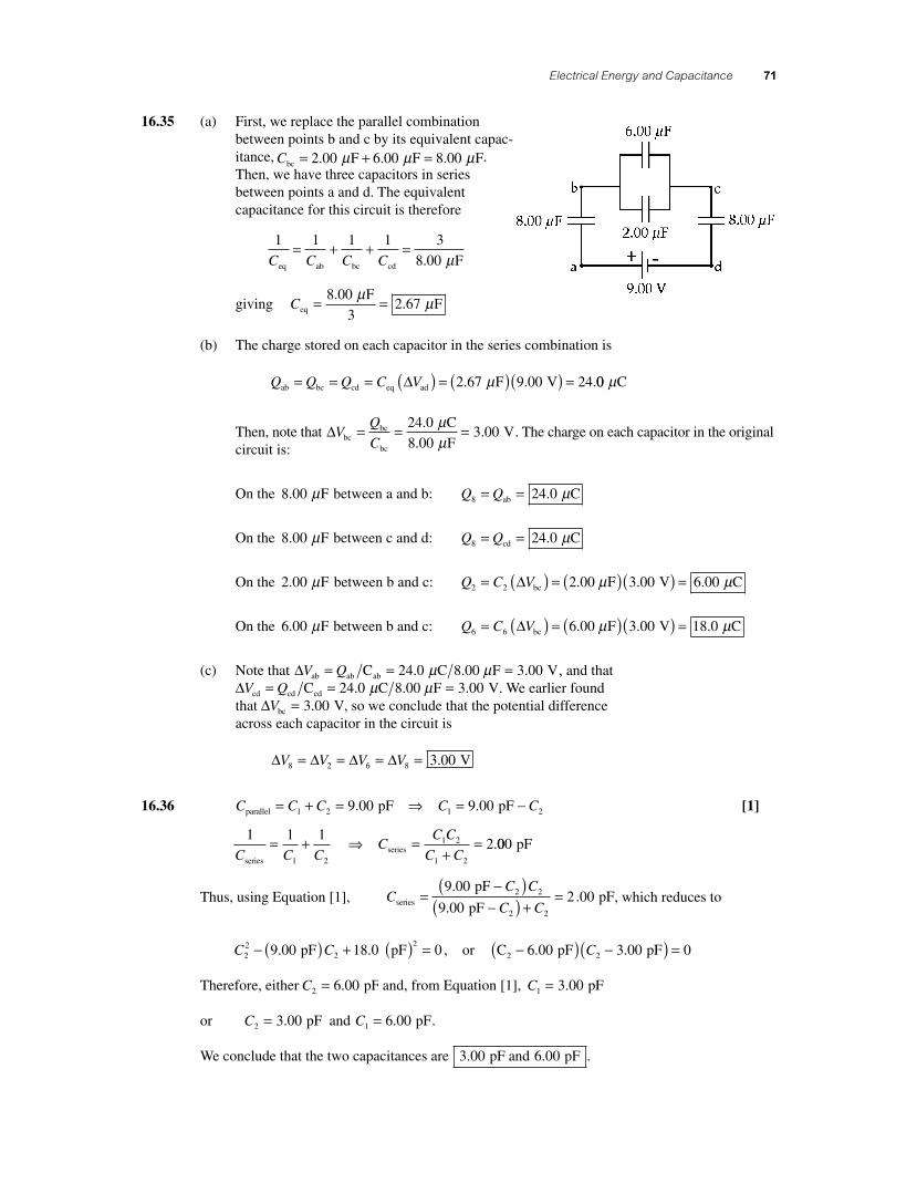
16.35 (a) First, we replace the parallel combination between points b and c by its equivalent capac-itance, Cbc = + =2 00 6 00 8 00. . . F F Fμ μ μ . Then, we have three capacitors in series between points a and d. The equivalent capacitance for this circuit is therefore
1 1 1 1 3
8 00C C C Ceq ab bc cd F= + + =
. μ
giving Ceq
F F= =8 00
32 67
..
μ μ
(b) The charge stored on each capacitor in the series combination is
Q Q Q C Vab bc cd eq ad F V= = = ( ) = ( )( ) =Δ 2 67 9 00 24. . .μ 00 Cμ
Then, note that ΔVQ
Cbcbc
bc
C
F V= = =24 0
8 003 00
.
..
μμ
. The charge on each capacitor in the original circuit is:
On the 8 00. Fμ between a and b: Q Q8 24 0= =ab C. μ
On the 8 00. Fμ between c and d: Q Q8 24 0= =cd C. μ
On the 2 00. Fμ between b and c: Q C V2 2 3 00 6 00= ( ) = ( )( ) =Δ bc 2.00 F V Cμ μ. .
On the 6 00. Fμ between b and c: Q C V6 6 3 00 18 0= ( ) = ( )( ) =Δ bc 6.00 F V Cμ μ. .
(c) Note that ΔV Qab ab abC C 8.00 F V= = =24 0 3 00. .μ μ , and that ΔV Qcd cd cdC C 8.00 F V= = =24 0 3 00. .μ μ . We earlier found that ΔVbc V= 3 00. , so we conclude that the potential difference across each capacitor in the circuit is
Δ Δ Δ ΔV V V V8 2 6 8 3 00= = = = . V
16.36 C C C C Cparallel pF pF= + = ⇒ = −1 2 1 29 00 9 00. . [1]
1 1 1
21 2
1 2
1 2C C CC
C C
C Cseriesseries = + ⇒ =
+= .000 pF
Thus, using Equation [1], pF
pFseriesCC C
C C=
−( )−( ) +
=9 00
9 002 002 2
2 2
.
.. pF, which reduces to
C C22
2
29 00 18 0 0− ( ) + ( ) =. . pF pF , or C pF pF2 −( ) −( ) =6 00 3 00 02. .C
Therefore, either C2 6 00= . pF and, from Equation [1], C1 3 00= . pF
or C2 3 00= . pF and C1 6 00= . pF.
We conclude that the two capacitances are 3 00 6 00. . pF and pF .
56157_16_ch16_p039-085.indd 7156157_16_ch16_p039-085.indd 71 3/18/08 10:45:04 PM3/18/08 10:45:04 PM
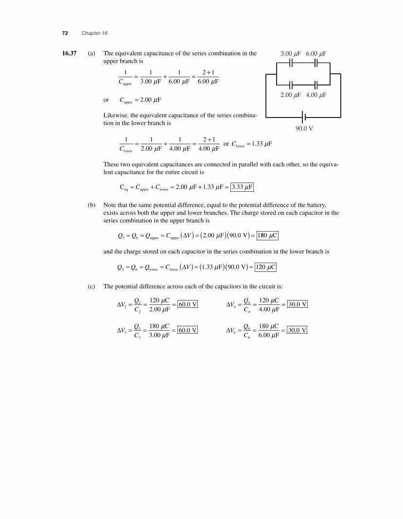
72 Chapter 16
16.37 (a) The equivalent capacitance of the series combination in the upper branch is
1 1
3 00
1
6 00
2 1
6 00Cupper F F F= + = +
. . .µ µ µ
or Cupper F= 2 00. µ
Likewise, the equivalent capacitance of the series combina-tion in the lower branch is
1 1
2 00
1
4 00
2 1
4 00Clower F F F= + = +
. . .µ µ µ or Clower F= 1 33. µ
These two equivalent capacitances are connected in parallel with each other, so the equiva-lent capacitance for the entire circuit is
C F F Feq upper lower= + = + =C C 2 00 1 33 3 33. . .µ µ µ
(b) Note that the same potential difference, equal to the potential difference of the battery, exists across both the upper and lower branches. The charge stored on each capacitor in the series combination in the upper branch is
Q Q Q C V3 6 2 00 90 0 1= = = ( ) = ( )( ) =upper upper F V∆ . .µ 880 Cµ
and the charge stored on each capacitor in the series combination in the lower branch is
Q Q Q C V3 6 1 33 90 0 1= = = ( ) = ( )( ) =lower lower F V∆ . .µ 220 Cµ
(c) The potential difference across each of the capacitors in the circuit is:
∆VQ
C22
2
12060 0= = = C
2.00 F V
µµ
. ∆VQ
C44
4
12030 0= = = C
4.00 F V
µµ
.
∆VQ
C33
3
18060 0= = = C
3.00 F V
µµ
. ∆VQ
C66
6
18030 0= = = C
6.00 F V
µµ
.
3.00 mF 6.00 mF
2.00 mF
90.0 V
4.00 mF
56157_16_ch16_p039-085.indd 7256157_16_ch16_p039-085.indd 72 3/18/08 1:23:44 PM3/18/08 1:23:44 PM
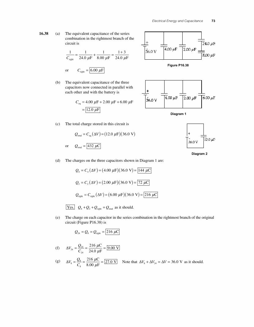
Electrical Energy and Capacitance 73
16.38 (a) The equivalent capacitance of the series combination in the rightmost branch of the circuit is
1 1
24 0
1
8 00
1 3
24 0Cright F F F= + = +
. . .μ μ μ
or Cright F= 6 00. μ
(b) The equivalent capacitance of the three capacitors now connected in parallel with each other and with the battery is
Ceq F F F
F
= + +
=
4 00 2 00 6 00
12 0
. . .
.
μ μ μ
μ
(c) The total charge stored in this circuit is
Q C Vtotal eq= ( ) = ( )( )Δ 12 0 36 0. . F Vμ
or Qtotal C= 432 μ
(d) The charges on the three capacitors shown in Diagram 1 are:
Q C V4 4 F V C= ( ) = ( )( ) =Δ 4 00 36 0 144. .μ μ
Q C V2 2 F V C= ( ) = ( )( ) =Δ 2 00 36 0 72. .μ μ
Q C Vright right F V C= ( ) = ( )( ) =Δ 6 00 36 0 216. .μ μ
Yes. as it should.Q Q Q Q4 2+ + =right total
(e) The charge on each capacitor in the series combination in the rightmost branch of the original circuit (Figure P16.38) is
Q Q Q24 8 216= = =right Cμ
(f) ΔVQ
C2424
24
216
24 09 00= = = C
F V
μμ.
.
(g) ΔVQ
C88
8
216
8 0027 0= = = C
F V
μμ.
. Note that Δ Δ ΔV V V8 24 36 0+ = = . V as it should.
Figure P16.38
Diagram 1
Diagram 2
56157_16_ch16_p039-085.indd 7356157_16_ch16_p039-085.indd 73 3/18/08 11:43:10 PM3/18/08 11:43:10 PM
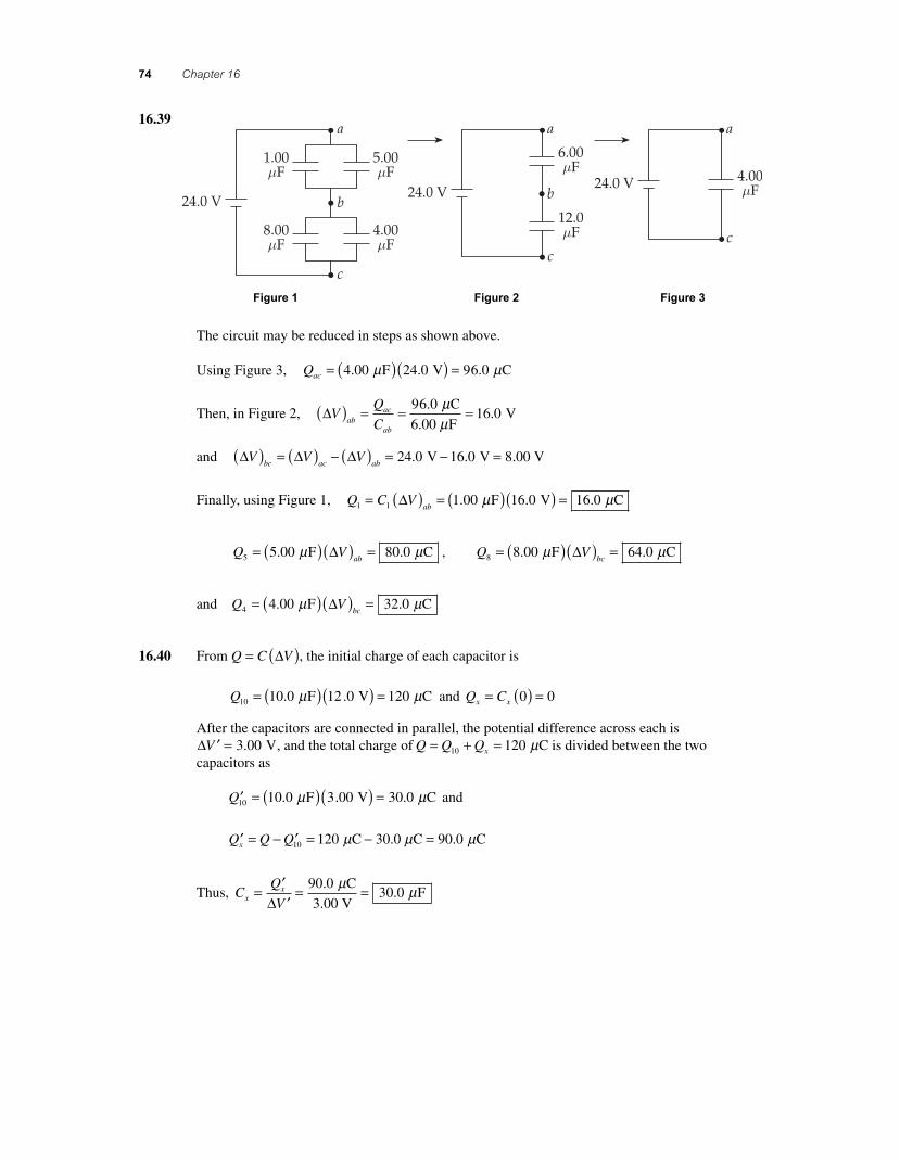
74 Chapter 16
16.39
Figure 1 Figure 2 Figure 3
The circuit may be reduced in steps as shown above.
Using Figure 3, Qac = ( )( ) =4 00 24 0 6 0. . . F V 9 Cμ μ
Then, in Figure 2, ΔVQ
Cabac
ab
( ) = = =9 C
6.00 F V
6 016 0
..
μμ
and Δ Δ ΔV V Vbc ac ab( ) = ( ) − ( ) = − =24 0 16 0. . V V 8.00 V
Finally, using Figure 1, Q C Vab1 1 1 00 16 0 16 0= ( ) = ( )( ) =Δ . . . F V Cμ μ
Q Vab5 5 00 80 0= ( )( ) =. . F Cμ μΔ , Q V
bc8 8 00 64 0= ( )( ) =. . F Cμ μΔ
and Q Vbc4 4 00 32 0= ( )( ) =. . F Cμ μΔ
16.40 From Q C V= ( )Δ , the initial charge of each capacitor is
Q10 10 0 12 0 120= ( )( ) =. . F V Cμ μ and Q Cx x= ( ) =0 0
After the capacitors are connected in parallel, the potential difference across each is Δ ′ =V 3 00. V, and the total charge of Q Q Qx= + =10 120 Cμ is divided between the two capacitors as
′ = ( )( ) =Q10 10 0 3 00 30 0. . . F V Cμ μ and
′ = − ′ = − =Q Q Qx 10 120 90 0 C 30.0 C Cμ μ μ.
Thus, CQ
Vxx= ′′
= =Δ
90 030 0
..
C
3.00 V F
μ μ
56157_16_ch16_p039-085.indd 7456157_16_ch16_p039-085.indd 74 3/19/08 2:00:04 AM3/19/08 2:00:04 AM
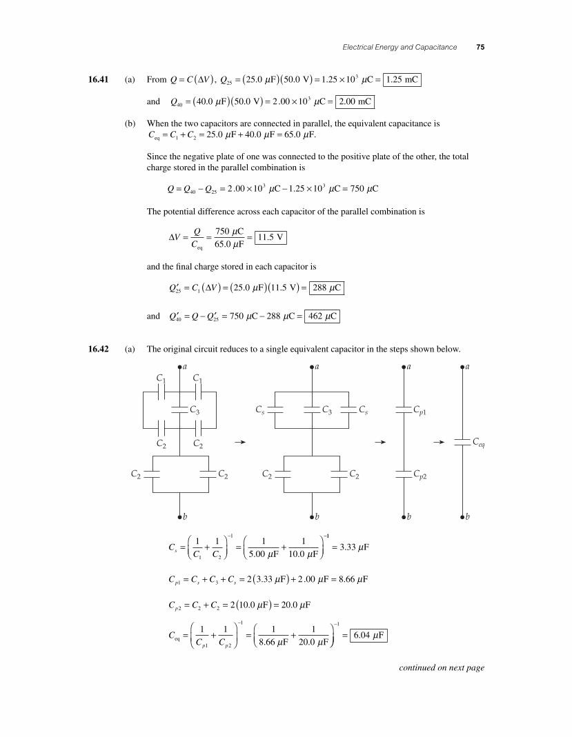
Electrical Energy and Capacitance 75
16.41 (a) From Q C V= ( )∆ , Q25325 0 50 0 1 25 10 1 25= ( )( ) = × =. . . . F V C mCµ µ
and Q40340 0 50 0 2 00 10 2 00= ( )( ) = × =. . . . F V C mCµ µ
(b) When the two capacitors are connected in parallel, the equivalent capacitance is C C Ceq F F F= + = + =1 2 25 0 40 0 65 0. . .µ µ µ .
Since the negative plate of one was connected to the positive plate of the other, the total charge stored in the parallel combination is
Q Q Q= − = × − × =40 253 32 00 10 1 25 10 750. . C C Cµ µ µ
The potential difference across each capacitor of the parallel combination is
∆VQ
C= = =
eq
C
65.0 F V
75011 5
µµ
.
and the fi nal charge stored in each capacitor is
′ = ( ) = ( )( ) =Q C V25 1 25 0 11 5 288∆ . . F V Cµ µ
and ′ = − ′ = − =Q Q Q40 25 750 288 462 C C Cµ µ µ
16.42 (a) The original circuit reduces to a single equivalent capacitor in the steps shown below.
CC Cs = +
⎛⎝⎜
⎞⎠⎟
= +⎛⎝⎜
⎞⎠⎟
− −1 1 1
5 00
1
10 01 2
1
. . F Fµ µ
11
3 33= . Fµ
C C C Cp s s1 3 2 3 33 2 00= + + = ( ) + =. . F F 8.66 Fµ µ µ
C C Cp2 2 2 2 1= + = ( ) =0.0 F 20.0 Fµ µ
CC Cp p
eq .66 F F= +
⎛
⎝⎜⎞
⎠⎟= +
⎛⎝⎜
⎞−
1 1 1
8
1
20 01 2
1
µ µ. ⎠⎠⎟=
−1
6 04. Fµ
continued on next page
56157_16_ch16_p039-085.indd 7556157_16_ch16_p039-085.indd 75 3/18/08 1:23:48 PM3/18/08 1:23:48 PM
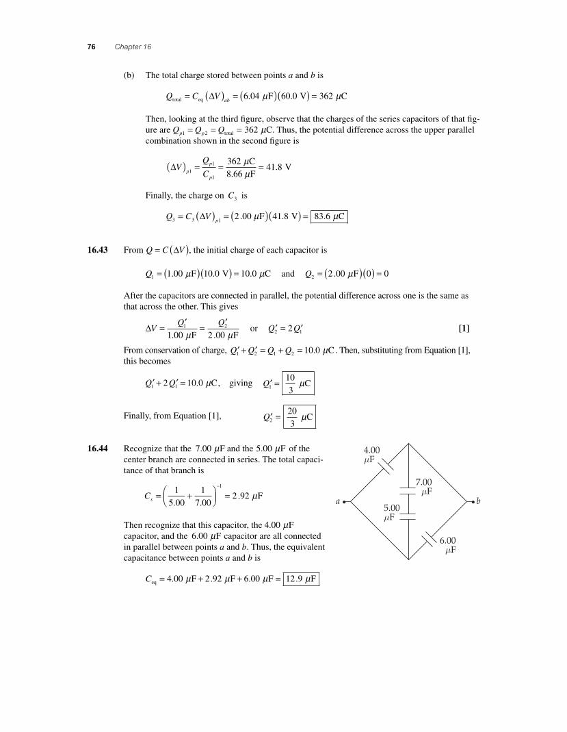
76 Chapter 16
(b) The total charge stored between points a and b is
Q C Vabtotal eq F V C= ( ) = ( )( ) =∆ 6 04 60 0 362. .µ µ
Then, looking at the third fi gure, observe that the charges of the series capacitors of that fi g-ure are Q Q Qp p1 2 362= = =total Cµ . Thus, the potential difference across the upper parallel combination shown in the second fi gure is
∆VQ
Cp
p
p
( ) = = =1
1
1
36241 8
C
8.66 F V
µµ
.
Finally, the charge on C3 is
Q C Vp3 3 1
2 41 8 83 6= ( ) = ( )( ) =∆ .00 F V Cµ µ. .
16.43 From Q C V= ( )∆ , the initial charge of each capacitor is
Q1 1 00 10 0 10 0= ( )( ) =. . . F V Cµ µ and Q2 2 00 0 0= ( )( ) =. Fµ
After the capacitors are connected in parallel, the potential difference across one is the same as that across the other. This gives
∆VQ Q= ′ = ′1 2
1 00 2 00. . F Fµ µ or ′ = ′Q Q2 12 [1]
From conservation of charge, ′ + ′ = + =Q Q Q Q1 2 1 2 10 0. Cµ . Then, substituting from Equation [1], this becomes
′ + ′ =Q Q1 12 10 0. Cµ , giving ′ =Q1 3
10 Cµ
Finally, from Equation [1], ′ =Q2 3
20 Cµ
16.44 Recognize that the 7 00 5 00. . F and the Fµ µ of the center branch are connected in series. The total capaci-tance of that branch is
Cs = +⎛⎝⎜
⎞⎠⎟ =
−1
5 00
1
7 002 92
1
. .. Fµ
Then recognize that this capacitor, the 4 00. Fµ capacitor, and the 6 00. Fµ capacitor are all connected in parallel between points a and b. Thus, the equivalent capacitance between points a and b is
Ceq F F F F= + + =4 00 2 92 6 00 12 9. . . .µ µ µ µ
56157_16_ch16_p039-085.indd 7656157_16_ch16_p039-085.indd 76 3/18/08 1:23:49 PM3/18/08 1:23:49 PM
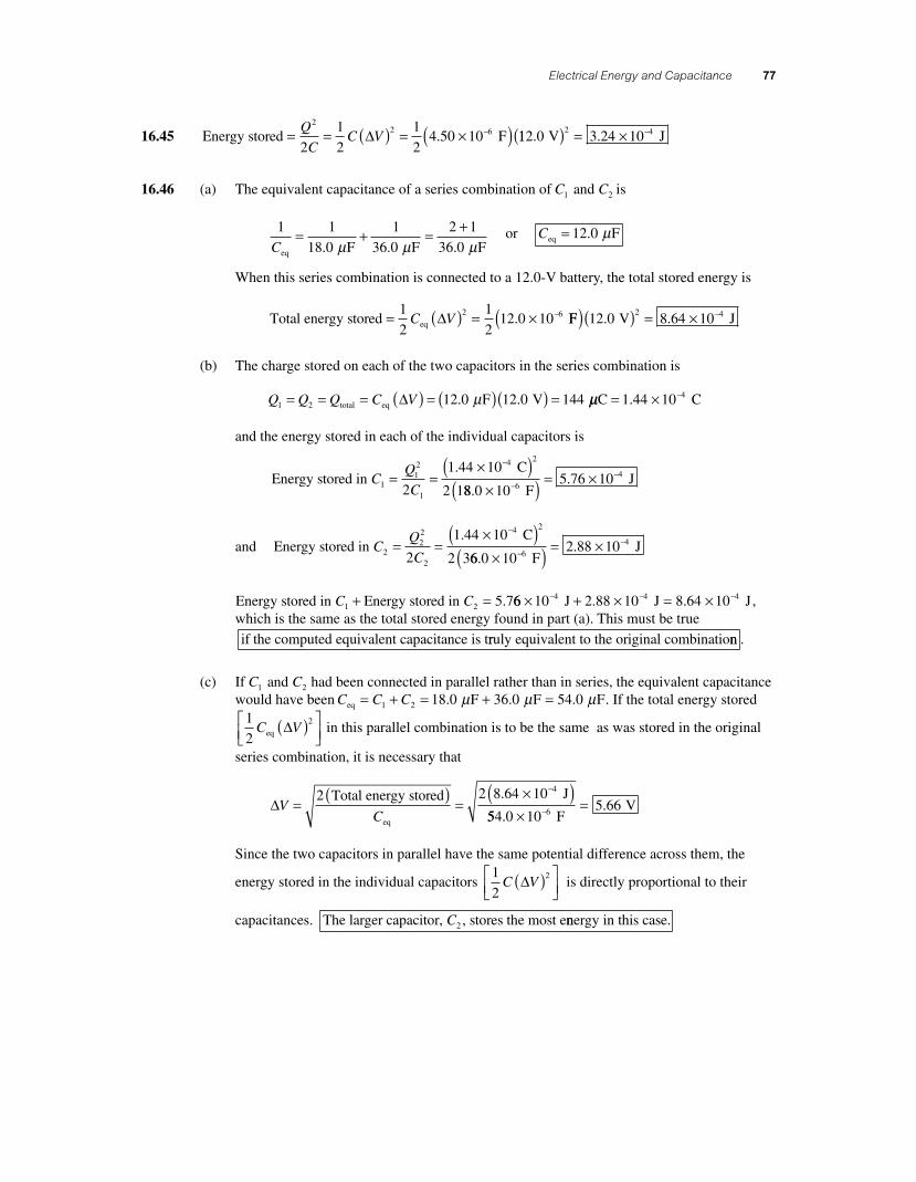
Electrical Energy and Capacitance 77
16.45 Energy stored F= = ( ) = ×( )−Q
CC V
22 6
2
1
2
1
24 50 10∆ . 112 0 3 24 10
2 4. . V J( ) = × −
16.46 (a) The equivalent capacitance of a series combination of C C1 2 and is
1 1
18 0
1
36 0
2 1
36 0Ceq F F F= + = +
. . .µ µ µ or Ceq F= 12 0. µ
When this series combination is connected to a 12.0-V battery, the total stored energy is
Total energy stored eq= ( ) = × −1
2
1
212 0 10
2 6C V∆ . FF V J( )( ) = × −12 0 8 64 102 4. .
(b) The charge stored on each of the two capacitors in the series combination is
Q Q Q C V1 2 12 0 12 0 144= = = ( ) = ( )( ) =total eq F V ∆ . .µ µµC C= × −1 44 10 4.
and the energy stored in each of the individual capacitors is
Energy stored in C
CQ
C112
1
4 2
2
1 44 10
2 1= =
×( )−.
88 0 105 76 10
64
..
×( ) = ×−−
F J
and Energy stored in C
CQ
C222
2
4 2
2
1 44 10
2 3= =
×( )−.
66 0 102 88 10
64
..
×( ) = ×−−
F J
Energy stored in Energy stored in C C1 2 5 7+ = . 66 10 2 88 10 8 64 104 4 4× + × = ×− − − J J J. . , which is the same as the total stored energy found in part (a). This must be true if the computed equivalent capacitance is trruly equivalent to the original combinationn .
(c) If C C1 2 and had been connected in parallel rather than in series, the equivalent capacitance would have been C C Ceq F F F= + = + =1 2 18 0 36 0 54 0. . .µ µ µ . If the total energy stored
1
22
C Veq ∆( )⎡⎣⎢
⎤⎦⎥
in this parallel combination is to be the same as was stored in the original
series combination, it is necessary that
∆VC
=( ) =
×( )−2 2 8 64 10 4
Total energy stored J
eq
.
554 0 105 666..
×=− F
V
Since the two capacitors in parallel have the same potential difference across them, the
energy stored in the individual capacitors 1
22
C V∆( )⎡⎣⎢
⎤⎦⎥
is directly proportional to their
capacitances. The larger capacitor, , stores the most eC2 nnergy in this case.
56157_16_ch16_p039-085.indd 7756157_16_ch16_p039-085.indd 77 3/18/08 1:23:50 PM3/18/08 1:23:50 PM
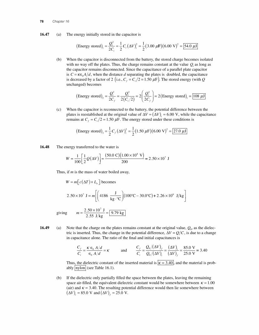
78 Chapter 16
16.47 (a) The energy initially stored in the capacitor is
Energy stored ( ) = = ( ) =1
22
2
1
2
1
23 00
Q
CC Vi
ii i
∆ . µFF V J( )( ) =6 00 54 02
. . µ
(b) When the capacitor is disconnected from the battery, the stored charge becomes isolated with no way off the plates. Thus, the charge remains constant at the value Qi as long as the capacitor remains disconnected. Since the capacitance of a parallel plate capacitor is C = ∈κ 0 A d , when the distance d separating the plates is doubled, the capacitance is decreased by a factor of 2 i.e., C Cf i= =( )2 1 50. Fµ . The stored energy (with Q unchanged) becomes
Energy stored( ) = = ( ) =⎛
⎝2
2 2 2
2 2 22
2
Q
C
Q
C
Q
Ci
f
i
i
i
f⎜⎜
⎞
⎠⎟= ( ) =2 108
1Energy stored Jµ
(c) When the capacitor is reconnected to the battery, the potential difference between the plates is reestablished at the original value of ∆ ∆V V
i= ( ) = 6 00. V, while the capacitance
remains at C Cf i= =2 1 50. Fµ . The energy stored under these conditions is
Energy stored F( ) = ( ) = ( )3
21
2
1
21 50 6 00C Vf i
∆ . .µ V J( ) =227 0. µ
16.48 The energy transferred to the water is
W Q V= ( )⎡⎣⎢
⎤⎦⎥
=( ) ×( )1
100
1
2
50 0 1 00 108
∆. . C V
200== ×2 50 107. J
Thus, if m is the mass of water boiled away,
W m c T L= ( ) +⎡⎣ ⎤⎦∆ v becomes
2 50 10 4186 100 30 07. .× =⋅
⎛⎝⎜
⎞⎠⎟
−( ) J J
kg CC Cm
°° ° ++ ×
⎡
⎣⎢
⎤
⎦⎥2 26 106. J kg
giving m = × =2 50 109 79
7..
J
2 .55 J kg kg
16.49 (a) Note that the charge on the plates remains constant at the original value, Q0, as the dielec-tric is inserted. Thus, the change in the potential difference, ∆V Q C= , is due to a change in capacitance alone. The ratio of the fi nal and initial capacitances is
C
C
A d
A df
i
= ∈∈
=κ κ0
0
and C
C
Q V
Q V
V
Vf
i
f
i
i
f
=( )( ) =
( )( ) =0
0
85 0
25 0
∆∆
∆∆
.
.
V
V== 3 40.
Thus, the dielectric constant of the inserted material is κ = 3 40. , and the material is prob-ably nylon (see Table 16.1).
(b) If the dielectric only partially fi lled the space between the plates, leaving the remaining space air-fi lled, the equivalent dielectric constant would be somewhere between κ = 1 00. (air) and κ = 3 40. . The resulting potential difference would then lie somewhere between ∆V
i( ) = 85 0. V and ∆Vf( ) = 25 0. V.
56157_16_ch16_p039-085.indd 7856157_16_ch16_p039-085.indd 78 3/18/08 1:23:51 PM3/18/08 1:23:51 PM
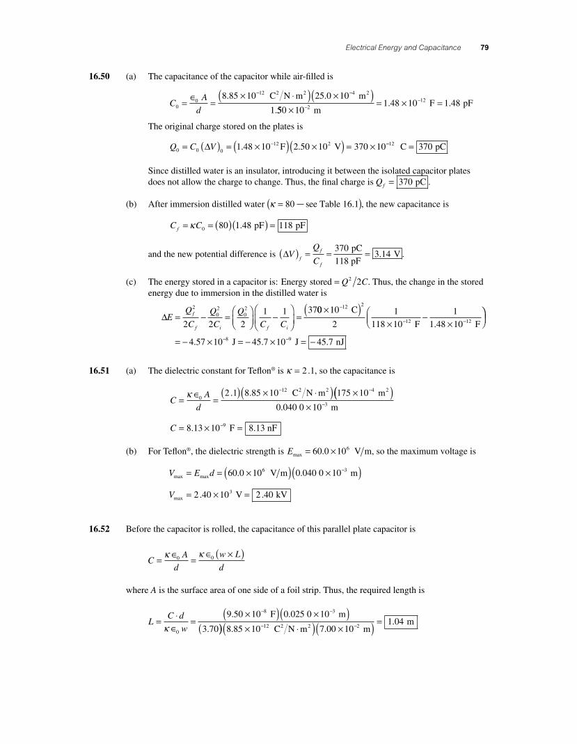
Electrical Energy and Capacitance 79
16.50 (a) The capacitance of the capacitor while air-fi lled is
CA
d00
12 48 85 10 25 0 10
1= ∈ =
× ⋅( ) ×( )− −. .
.
C N m m2 2 2
550 101 48 10 1 482
12
×= × =−
−
m F pF. .
The original charge stored on the plates is
Q C V0 0 021 48 10 2 50 10 370 10= ( ) = ×( ) ×( ) = ×−∆ . .12 F V −− =12 370 C pC
Since distilled water is an insulator, introducing it between the isolated capacitor plates does not allow the charge to change. Thus, the fi nal charge is Qf = 370 pC .
(b) After immersion distilled water κ =( )80 see Table 16.1 , the new capacitance is
C Cf = = ( )( ) =κ 0 80 1 48 118. pF pF
and the new potential difference is ∆VQ
Cf
f
f
( ) = = =3703 14
pC
118 pF V. .
(c) The energy stored in a capacitor is: Energy stored = Q C2 2 . Thus, the change in the stored energy due to immersion in the distilled water is
∆E = − =⎛⎝⎜
⎞⎠⎟
−⎛
⎝⎜⎞
⎠⎟=
Q
C
Q
C
Q
C Cf
f i f i
2
02
02
2 2 2
1 1 3700 10
2
1
118 10
1
1 48 10
12 2
12 12
×( )×
−×
⎛⎝⎜
−
− −
C
F F.⎞⎞⎠⎟
= − × = − × = −− −4 57 10 45 7 10 45 78 9. . . J J nJ
16.51 (a) The dielectric constant for Tefl on® is κ = 2 1. , so the capacitance is
CA
d= ∈ =
( ) × ⋅( ) ×− −κ 0
12 42 1 8 85 10 175 10. . C N m m2 2 2(( )× −0 10 m3.040 0
C = × =−8 13 10 8 139. . F nF
(b) For Tefl on®, the dielectric strength is Emax = ×60 0 10. 6 V m, so the maximum voltage is
V E dmax max6 3 V m m= = ×( ) ×( )−60 0 10 0 040 0 10. .
Vmax V kV= × =2 40 10 2 403. .
16.52 Before the capacitor is rolled, the capacitance of this parallel plate capacitor is
CA
d
w L
d= ∈ =
∈ ×( )κ κ0 0
where A is the surface area of one side of a foil strip. Thus, the required length is
LC d
w= ⋅
∈=
×( ) ×( )(
− −
κ 0
8 39 50 10 0 025 0 10. . F m
3.70)) × ⋅( ) ×( ) =− −8 85 10 7 00 101 04
12 2. ..
C N m m m
2 2
56157_16_ch16_p039-085.indd 7956157_16_ch16_p039-085.indd 79 3/18/08 1:23:52 PM3/18/08 1:23:52 PM
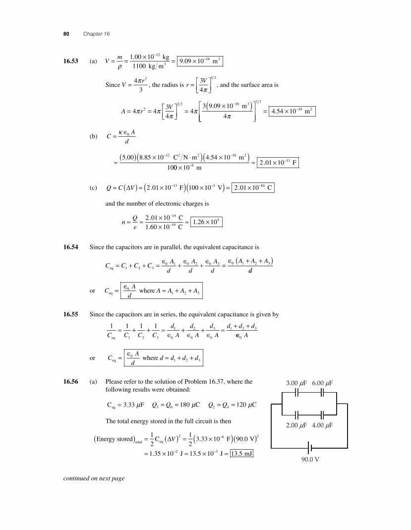
80 Chapter 16
16.53 (a) Vm= = × = ×
−−
ρ1 00 10
9 09 1012
16..
kg
1100 kg m m3
3
Since Vr= 4
3
3π, the radius is r
V= ⎡⎣⎢
⎤⎦⎥
3
4
1 3
π, and the surface area is
A rV= = ⎡
⎣⎢⎤⎦⎥
=×( )⎡ −
4 43
44
3 9 09 10
42
2 3 16
π ππ
ππ
. m3
⎣⎣⎢⎢
⎤
⎦⎥⎥
= × −
2 3
104 54 10. m2
(b) CA
d= ∈κ 0
=( ) × ⋅( ) ×( )− −5 00 8 85 10 4 54 10
10
12 10. . . C N m m2 2 2
00 102 01 109
13
×= ×−
−
m F.
(c) Q C V= ( ) = ×( ) ×( ) = ×− − −∆ 2 01 10 1 2 01 1013. . F 00 10 V3 114 C
and the number of electronic charges is
nQ
e= = ×
×= ×
−
−
2 01 101 26 10
145.
. C
1.60 10 C19
16.54 Since the capacitors are in parallel, the equivalent capacitance is
C C C CA
d
A
d
A
d
A A Aeq = + + = ∈ + ∈ + ∈ =
∈ + +( )1 2 3
0 1 0 2 0 3 0 1 2 3
dd
or CA
dA A A Aeq where = ∈ = + +0
1 2 3
16.55 Since the capacitors are in series, the equivalent capacitance is given by
1 1 1 1
1 2 3
1
0
2
0
3
0
1 2 3
C C C C
d
A
d
A
d
A
d d d
eq
= + + =∈
+∈
+∈
= + +∈∈0 A
or CA
dd d d deq where = ∈ = + +0
1 2 3
16.56 (a) Please refer to the solution of Problem 16.37, where the following results were obtained:
C Feq = 3 33. µ Q Q3 6 180= = Cµ Q Q2 4 120= = Cµ
The total energy stored in the full circuit is then
Energy stored C
total eq( ) = ( ) = × −1
2
1
23 33 10
2 6∆V . F V
J J
( )( )
= × = × =− −
90 0
1 35 10 13 5 10 13 5
2
2 3
.
. . . mJ
3.00 mF 6.00 mF
2.00 mF
90.0 V
4.00 mF
continued on next page
56157_16_ch16_p039-085.indd 8056157_16_ch16_p039-085.indd 80 3/18/08 1:23:52 PM3/18/08 1:23:52 PM
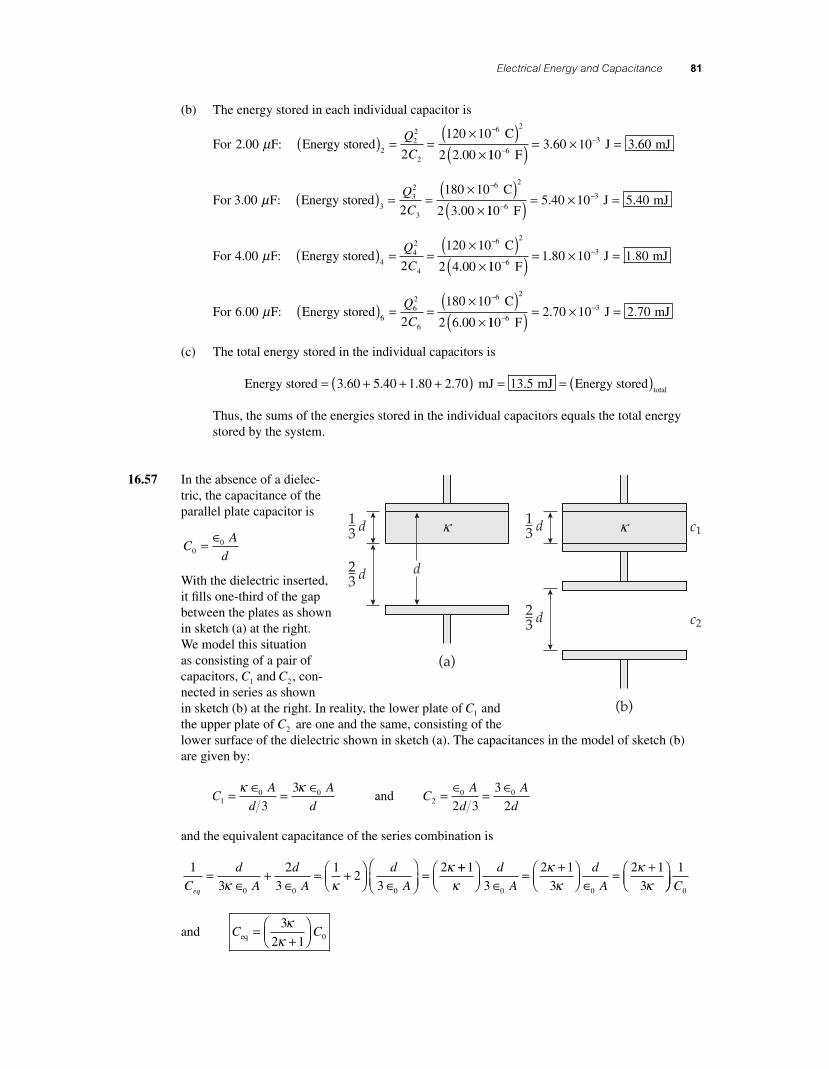
Electrical Energy and Capacitance 81
(b) The energy stored in each individual capacitor is
For 2 00. Fµ : Energy stored C( ) = =
×( )×
−
222
2
6 2
2
120 10
2 2 00
Q
C . 1103 60 10 3 60
63
−−
( ) = × = F
J mJ. .
For 3 00. Fµ : Energy stored C( ) = =
×( )×
−
332
3
6 2
2
180 10
2 3 00
Q
C . 1105 40 10 5 40
63
−−
( ) = × = F
J mJ. .
For 4 00. Fµ : Energy stored C( ) = =
×( )×
−
442
4
6 2
2
120 10
2 4 00
Q
C . 1101 80 10 1 80
63
−−
( ) = × = F
J mJ. .
For 6 00. Fµ : Energy stored C( ) = =
×( )×
−
662
6
6 2
2
180 10
2 6 00
Q
C . 1102 70 10 2 70
63
−−
( ) = × = F
J mJ. .
(c) The total energy stored in the individual capacitors is
Energy stored 3.60 mJ= + + +( ) =5 40 1 80 2 70 13 5. . . . mJ Energy storedtotal
= ( )
Thus, the sums of the energies stored in the individual capacitors equals the total energy stored by the system.
16.57 In the absence of a dielec-tric, the capacitance of the parallel plate capacitor is
CA
d00= ∈
With the dielectric inserted, it fi lls one-third of the gap between the plates as shown in sketch (a) at the right. We model this situation as consisting of a pair of capacitors, C1 and C2 , con-nected in series as shown in sketch (b) at the right. In reality, the lower plate of C1 and the upper plate of C2 are one and the same, consisting of the lower surface of the dielectric shown in sketch (a). The capacitances in the model of sketch (b) are given by:
CA
d
A
d10 0
3
3= ∈ = ∈κ κ and C
A
d
A
d20 0
2 3
3
2= ∈ = ∈
and the equivalent capacitance of the series combination is
1
3
2
3
12
3
2
0 0 0C
d
A
d
A
d
Aeq
=∈
+∈
= +⎛⎝⎜
⎞⎠⎟ ∈
⎛⎝⎜
⎞⎠⎟
=κ κ
κ ++⎛⎝⎜
⎞⎠⎟ ∈
= +⎛⎝⎜
⎞⎠⎟ ∈
= +⎛⎝⎜
⎞1
3
2 1
3
2 1
30 0κκ
κκ
κd
A
d
A ⎠⎠⎟1
0C
and C Ceq =+
⎛⎝⎜
⎞⎠⎟
3
2 1 0
κκ
13 d
23 d
d
(a)
k c1
c2
(b)
13 d k
23 d
56157_16_ch16_p039-085.indd 8156157_16_ch16_p039-085.indd 81 3/18/08 1:23:53 PM3/18/08 1:23:53 PM
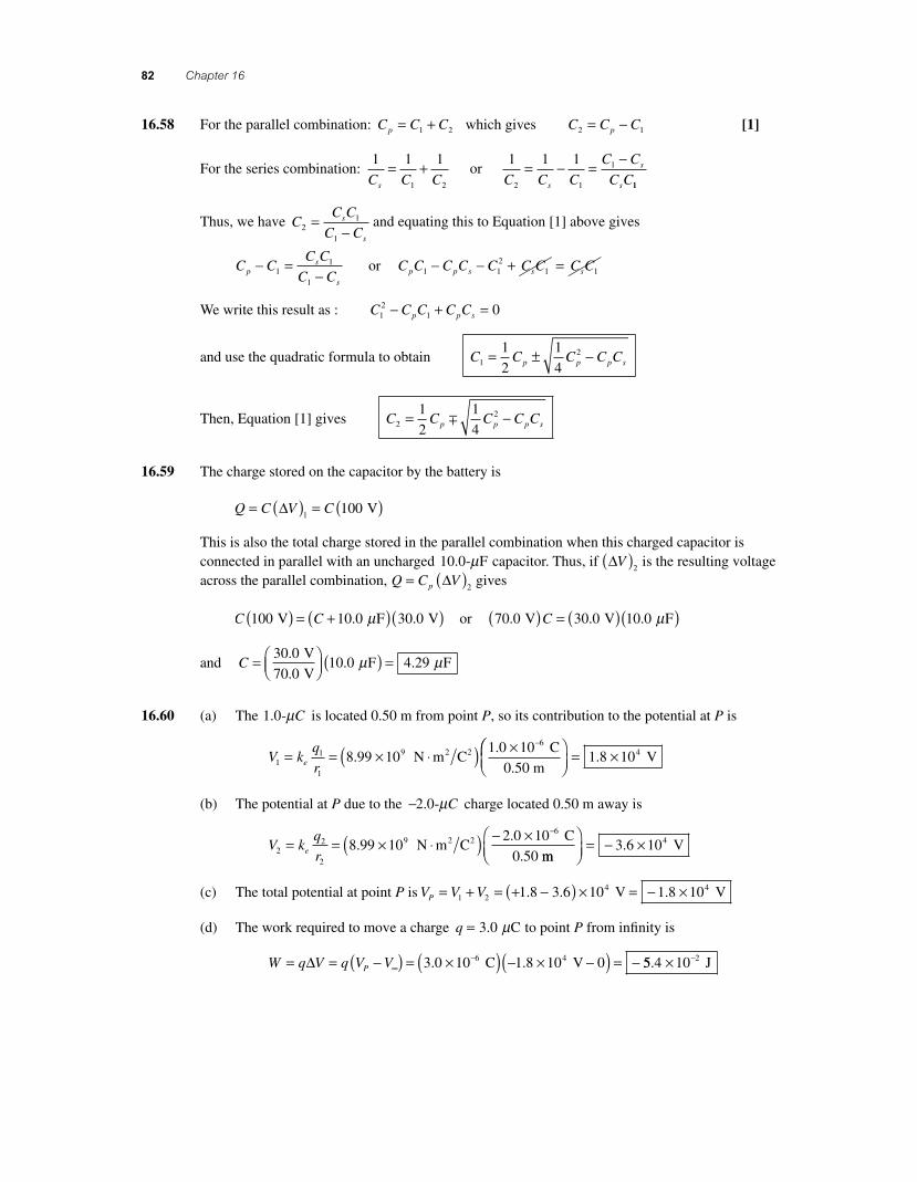
82 Chapter 16
16.58 For the parallel combination: C C Cp = +1 2 which gives C C Cp2 1= − [1]
For the series combination: 1 1 1 1 1 1
1 2 2 1
1
C C C C C C
C C
C Cs s
s
s
= + = − = − or
11
Thus, we have CC C
C Cs
s2
1
1
=−
and equating this to Equation [1] above gives
C CC C
C Cps
s
− =−1
1
1
or C C C C C C C C Cp p s s s1 12
1 1− − + =
We write this result as : C C C C Cp p s12
1 0− + =
and use the quadratic formula to obtain C C C C Cp p p s121
2
1
4= ± −
Then, Equation [1] gives C C C C Cp p p s221
2
1
4= −∓
16.59 The charge stored on the capacitor by the battery is
Q C V C= ( ) = ( )∆
1100 V
This is also the total charge stored in the parallel combination when this charged capacitor is connected in parallel with an uncharged 10 0. - Fµ capacitor. Thus, if ∆V( )2
is the resulting voltage across the parallel combination, Q C Vp= ( )∆
2 gives
C C100 10 0 30 0 V F V( ) = +( )( ). .µ or 70 0 30 0 10 0. . . V V F( ) = ( )( )C µ
and C = ⎛⎝⎜
⎞⎠⎟ ( ) =30 0
70 010 0 4 29
.
.. .
V
V F Fµ µ
16.60 (a) The 1 0. -µC is located 0.50 m from point P, so its contribution to the potential at P is
V kq
re11
1
96
8 99 101 0 10= = × ⋅( ) × −
..
N m C C
0.50 m2 2 ⎛⎛
⎝⎜⎞⎠⎟
= ×1 8 104. V
(b) The potential at P due to the −2 0. -µC charge located 0.50 m away is
V kq
re22
2
96
8 99 102 0 10= = × ⋅( ) − × −
..
N m C C
0.50 2 2
mm V
⎛⎝⎜
⎞⎠⎟
= − ×3 6 104.
(c) The total potential at point P is V V VP = + = + −( ) × = − ×1 24 41 8 3 6 10 1 8 10. . . V V
(d) The work required to move a charge q = 3 0. Cµ to point P from infi nity is
W q V q V VP= = −( ) = ×( ) − × −( ) = −∞
−∆ 3 0 10 1 8 10 06 4. . C V 55 4 10 2. × − J
56157_16_ch16_p039-085.indd 8256157_16_ch16_p039-085.indd 82 3/18/08 1:23:54 PM3/18/08 1:23:54 PM
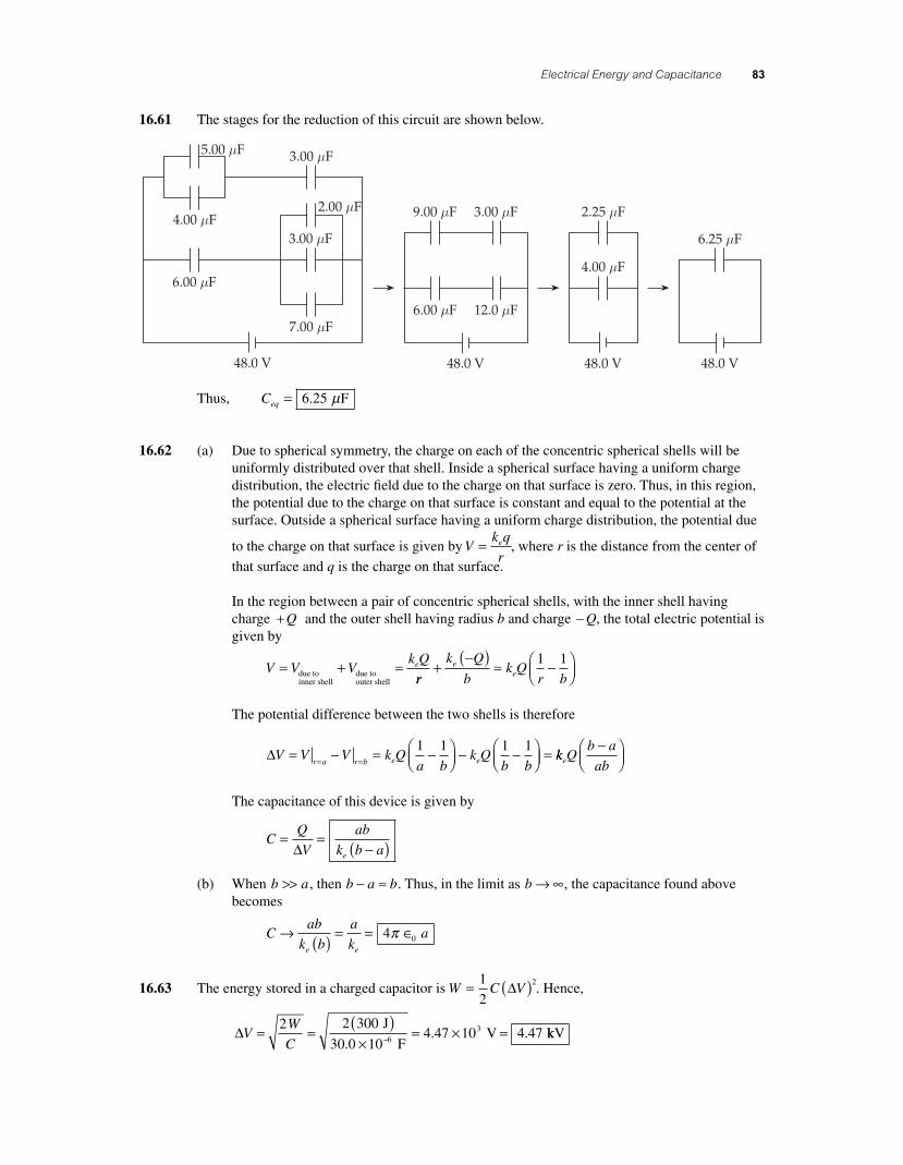
Electrical Energy and Capacitance 83
16.61 The stages for the reduction of this circuit are shown below.
Thus, Ceq = 6 25. Fµ
16.62 (a) Due to spherical symmetry, the charge on each of the concentric spherical shells will be uniformly distributed over that shell. Inside a spherical surface having a uniform charge distribution, the electric fi eld due to the charge on that surface is zero. Thus, in this region, the potential due to the charge on that surface is constant and equal to the potential at the surface. Outside a spherical surface having a uniform charge distribution, the potential due
to the charge on that surface is given by Vk q
re= , where r is the distance from the center of
that surface and q is the charge on that surface.
In the region between a pair of concentric spherical shells, with the inner shell having charge + Q and the outer shell having radius b and charge − Q, the total electric potential is given by
V V Vk Qe= + =due to
inner shelldue toouter shell rr
k Q
bk Q
r be
e+−( ) = −⎛
⎝⎜⎞⎠⎟
1 1
The potential difference between the two shells is therefore
∆V V V k Qa b
k Qb br a r b e e= − = −⎛
⎝⎜⎞⎠⎟ − −⎛
⎝⎜⎞⎠⎟ == =
1 1 1 1kk Q
b a
abe
−⎛⎝⎜
⎞⎠⎟
The capacitance of this device is given by
CQ
V
ab
k b ae
= =−( )∆
(b) When b a>> , then b a b− ≈ . Thus, in the limit as b → ∞, the capacitance found above becomes
Cab
k b
a
ka
e e
→ ( ) = = ∈4 0π
16.63 The energy stored in a charged capacitor is W C V= ( )1
22∆ . Hence,
∆VW
C= =
( )×
= × =−
2 2 3004 47 10 4 473 J
30.0 10 F V 6 . . kkV
56157_16_ch16_p039-085.indd 8356157_16_ch16_p039-085.indd 83 3/18/08 1:23:56 PM3/18/08 1:23:56 PM
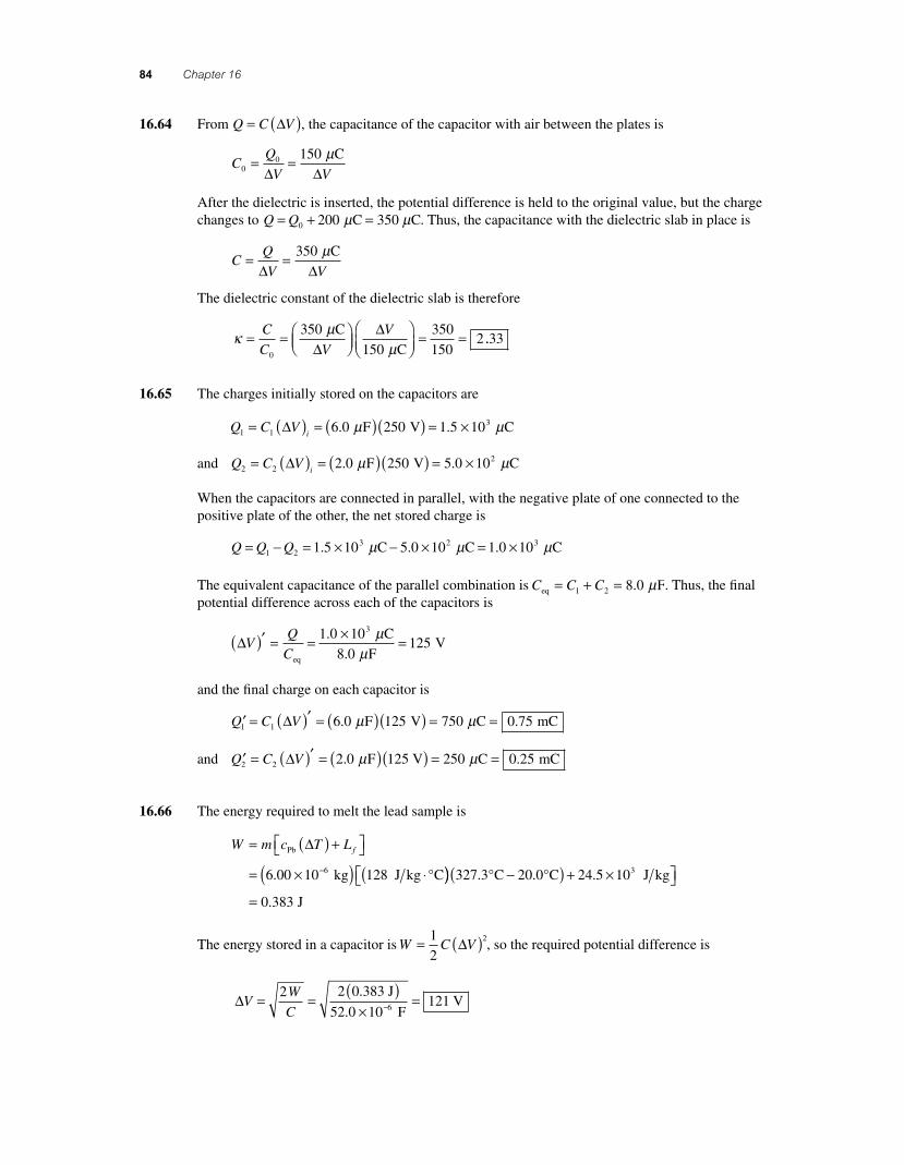
84 Chapter 16
16.64 From Q C V= ( )∆ , the capacitance of the capacitor with air between the plates is
CQ
V V00 150= =
∆ ∆ Cµ
After the dielectric is inserted, the potential difference is held to the original value, but the charge changes to Q Q= + =0 200 C 350 Cµ µ . Thus, the capacitance with the dielectric slab in place is
CQ
V V= =
∆ ∆350 Cµ
The dielectric constant of the dielectric slab is therefore
κ µµ
= = ⎛⎝⎜
⎞⎠⎟
⎛⎝⎜
⎞⎠⎟
= =C
C V
V
0
350
150
350
1502
C
C∆∆
..33
16.65 The charges initially stored on the capacitors are
Q C Vi1 1
36 0 250 1 5 10= ( ) = ( )( ) = ×∆ . . F V Cµ µ
and Q C Vi2 2
22 0 250 5 0 10= ( ) = ( )( ) = ×∆ . . F V Cµ µ
When the capacitors are connected in parallel, with the negative plate of one connected to the positive plate of the other, the net stored charge is
Q Q Q= − = × − × = ×1 23 2 31 5 10 5 0 10 1 0 10. . . C C Cµ µ µ
The equivalent capacitance of the parallel combination is C C Ceq F= + =1 2 8 0. µ . Thus, the fi nal potential difference across each of the capacitors is
∆VQ
C( )′ = = × =
eq
C
F V
1 0 10
8 0125
3.
.
µµ
and the fi nal charge on each capacitor is
′ = ( )′ = ( )( ) = =Q C V1 1 6 0 125 750 0 75∆ . . F V C mCµ µ
and ′ = ( )′ = ( )( ) = =Q C V2 2 2 0 1 250 0 25∆ . . F 25 V C mCµ µ
16.66 The energy required to melt the lead sample is
W m c T Lf= ( ) +⎡⎣ ⎤⎦
= ×( ) ⋅(−
Pb
kg J kg C
∆
6 00 10 1286. ° )) −( ) + ×⎡⎣ ⎤⎦=
327 3 20 0 24 5 10
0 383
3. . .
.
° °C C J kg
J
The energy stored in a capacitor is W C V= ( )1
22∆ , so the required potential difference is
∆VW
C= =
( )×
=−
2 2 0 383121
. J
52.0 10 F V6
56157_16_ch16_p039-085.indd 8456157_16_ch16_p039-085.indd 84 3/18/08 1:23:56 PM3/18/08 1:23:56 PM
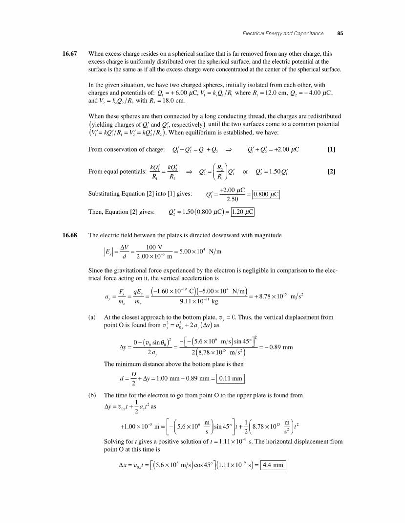
Electrical Energy and Capacitance 85
16.67 When excess charge resides on a spherical surface that is far removed from any other charge, this excess charge is uniformly distributed over the spherical surface, and the electric potential at the surface is the same as if all the excess charge were concentrated at the center of the spherical surface.
In the given situation, we have two charged spheres, initially isolated from each other, with charges and potentials of: Q1 6 00= + . Cµ , V k Q Re1 1 1= where R1 12 0= . cm, Q2 4 00= − . Cµ , and V k Q Re2 2 2= with R2 18 0= . cm.
When these spheres are then connected by a long conducting thread, the charges are redistributed yielding charges of and , respective′ ′Q Q1 2 lly( ) until the two surfaces come to a common potential
′= ′ = ′ = ′( )V kQ R V kQ R1 1 1 2 2 2 . When equilibrium is established, we have:
From conservation of charge: ′ + ′ = + ⇒Q Q Q Q1 2 1 2 ′ + ′ = +Q Q1 2 2 00. Cµ [1]
From equal potentials: kQ
R
kQ
RQ
R
RQ
′ = ′ ⇒ ′ =⎛⎝⎜
⎞⎠⎟
′1
1
2
22
2
11 or ′ = ′Q Q2 11 50. [2]
Substituting Equation [2] into [1] gives: ′ = + =Q1
2 00
2 500 800
.
..
C C
µ µ
Then, Equation [2] gives: ′ = ( ) =Q2 1 50 0 800 1 20. . . C Cµ µ
16.68 The electric fi eld between the plates is directed downward with magnitude
EV
dy = =×
= ×−
∆ 1005 00 104 V
2.00 10 m N m3 .
Since the gravitational force experienced by the electron is negligible in comparison to the elec-trical force acting on it, the vertical acceleration is
aF
m
qE
myy
e
y
e
= = =− ×( ) − ×( )−1 60 10 5 00 1019 4. . C N m
99 11 108 78 1031
15
..
×= + ×− kg
m s2
(a) At the closest approach to the bottom plate, vy = 0. Thus, the vertical displacement from point O is found from v vy y ya y2
02 2= + ( )∆ as
∆yay
=− ( )
=− − ×( )⎡⎣ ⎤⎦0
2
5 6 10 450 0
2 6v sin . sinθ m s °
22
152 8 78 100 89
..
×( ) = − m s
mm2
The minimum distance above the bottom plate is then
dD
y= + = − =2
1 00 0 89 0 11∆ . . . mm mm mm
(b) The time for the electron to go from point O to the upper plate is found from
∆y t a ty y= +v021
2 as
+ × = − ×⎛⎝⎜
⎞⎠⎟
⎡⎣⎢
⎤⎦⎥
−1 00 10 5 6 10 453 6. . sin m m
s° t ++ ×⎛
⎝⎜⎞⎠⎟
1
28 78 1015 2.
m
s2 t
Solving for t gives a positive solution of t = × −1 11 10 9. s. The horizontal displacement from point O at this time is
∆x tx= = ×( )⎡⎣ ⎤⎦ ×( ) =−v06 95 6 10 45 1 11 10. cos .m s s° 44 4. mm
56157_16_ch16_p039-085.indd 8556157_16_ch16_p039-085.indd 85 3/18/08 1:23:57 PM3/18/08 1:23:57 PM