Embed Size (px)
Citation preview
University Of Technology
Electrical and Electronics Department
المكائن الكهربائية
Electrical Drive 4th Class
Dr. Nowfal Mohammed Taher Al Kayat
Electrical Drive 4th Class Dr. Nowfal M.T. Al Kayat المكائن الكهربائية
1
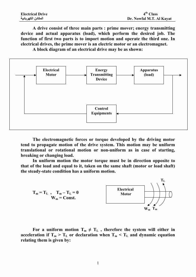
A drive consist of three main parts : prime mover; energy transmitting device and actual apparatus (load), which perform the desired job. The function of first two parts is to import motion and operate the third one. In electrical drives, the prime mover is an electric motor or an electromagnet.
A block diagram of an electrical drive may be as shown:
The electromagnetic forces or torque developed by the driving motor tend to propagate motion of the drive system. This motion may be uniform translational or rotational motion or non-uniform as in case of starting, breaking or changing load.
In uniform motion the motor torque must be in direction opposite to that of the load and equal to it, taken on the same shaft (motor or load shaft) the steady-state condition has a uniform motion.
Tm = TL , Tm – TL = 0 Wm = Const. For a uniform motion Tm ≠ TL , therefore the system will either in
acceleration if Tm > TL or declaration when Tm < TL and dynamic equation relating them is given by:
Electrical Motor
Energy Transmitting
Device
Apparatus (load)
Control Equipments
Electrical Motor
Wm Tm
TL
Electrical Drive 4th Class Dr. Nowfal M.T. Al Kayat المكائن الكهربائية
2
dtdw
Lm JTT =− , where J = moment of inertia of all rotating part transformed to the motor shaft. Types of the load: there are two main loads type:
Active load: which provides active torque (gravitational), deformation in elastic bodies, springs forces, compressed air, …) these load may cause motion of the system.
Passive loads : are that loads which have a torque all the times opposing the motion such as Frictional load and Shearing loads.
Also, loads may be subdivided into: Constant loads which are unchanged with time or with variation of speed. Linear varying loads TL = a + bw where a, b are constant. Second varying load (order) TL = a + bw + cw2 where a, b, c are constant and w is the speed. The frictional load may be considered constant, which pump load consider linear and compressor loads may consider second order. Electrical drive may operate in one of three main modes op operation:
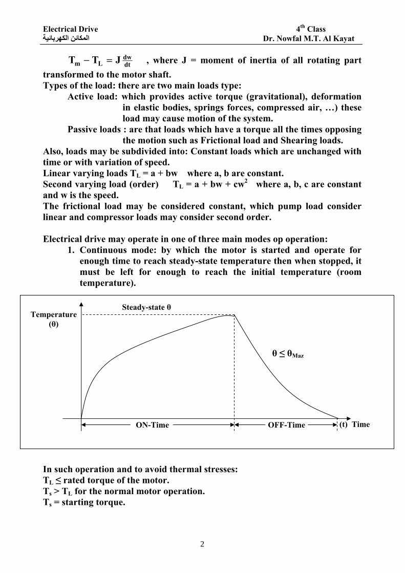
1. Continuous mode: by which the motor is started and operate for enough time to reach steady-state temperature then when stopped, it must be left for enough to reach the initial temperature (room temperature).
In such operation and to avoid thermal stresses: TL ≤ rated torque of the motor. Ts > TL for the normal motor operation. Ts = starting torque.
ON-Time OFF-Time (t) Time
Temperature (θ)
Steady-state θ
θ ≤ θMaz
Electrical Drive 4th Class Dr. Nowfal M.T. Al Kayat المكائن الكهربائية
3
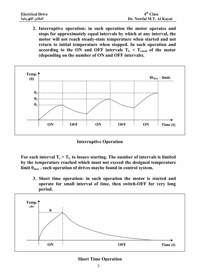
2. Interruptive operation: in such operation the motor operates and stops for approximately equal intervals by which at any interval, the motor will not reach steady-state temperature when started and not return to initial temperature when stopped. In such operation and according to the ON and OFF intervals TL < Trated of the motor (depending on the number of ON and OFF intervals).
For each interval Ts > TL to insure starting. The number of intervals is limited by the temperature reached which must not exceed the designed temperature limit θmax . such operation of drives maybe found in control system.
3. Short time operation: in such operation the motor is started and operate for small interval of time, then switch-OFF for very long period.
ON OFF OFF ON ON
Temp. (θ)
θ1
θ2
θ3
Time (t)
ΘMax – limit.
Interruptive Operation
ON OFF
Temp. (θ)
θ
Time (t)
Short Time Operation
Electrical Drive 4th Class Dr. Nowfal M.T. Al Kayat المكائن الكهربائية
4
θ may reach θMax but the long OFF time will be sufficient to return the temperature to its initial value.
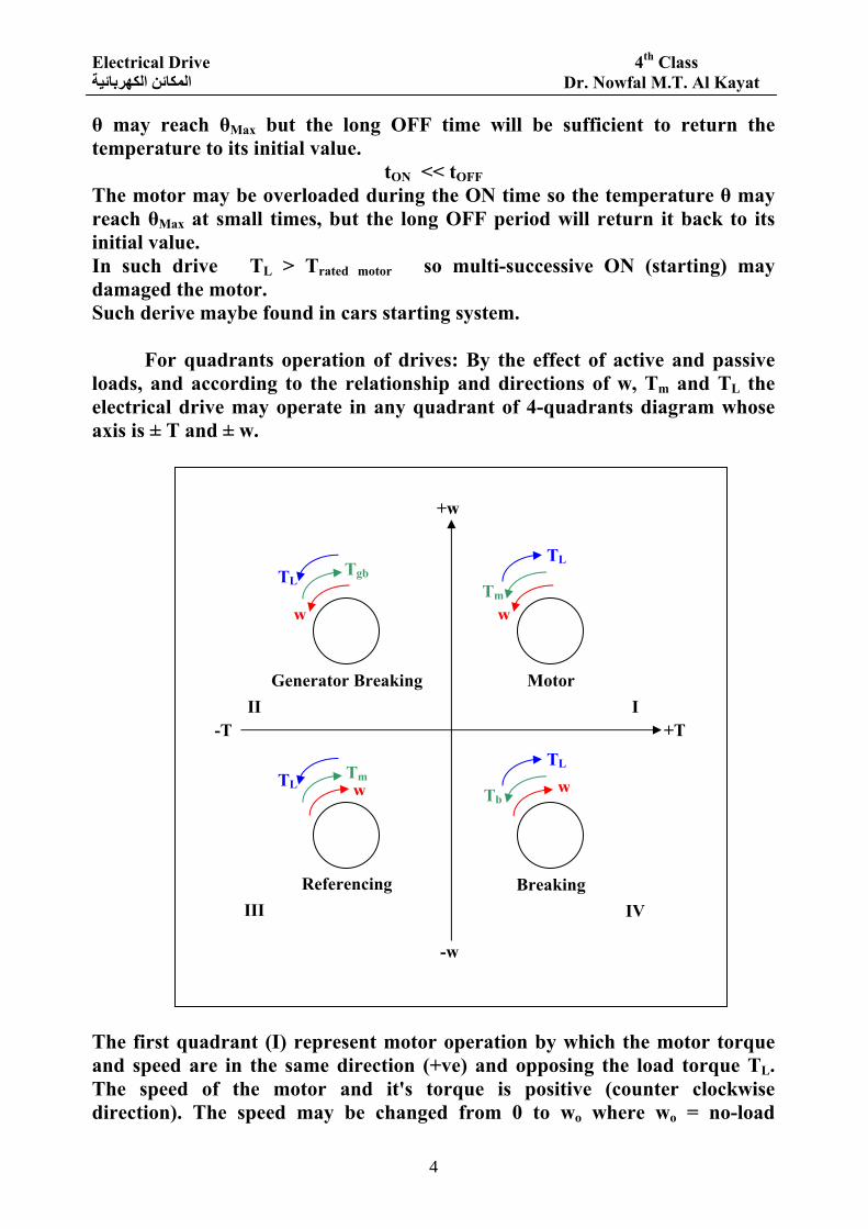
tON << tOFF The motor may be overloaded during the ON time so the temperature θ may reach θMax at small times, but the long OFF period will return it back to its initial value. In such drive TL > Trated motor so multi-successive ON (starting) may damaged the motor. Such derive maybe found in cars starting system. For quadrants operation of drives: By the effect of active and passive loads, and according to the relationship and directions of w, Tm and TL the electrical drive may operate in any quadrant of 4-quadrants diagram whose axis is ± T and ± w. The first quadrant (I) represent motor operation by which the motor torque and speed are in the same direction (+ve) and opposing the load torque TL. The speed of the motor and it's torque is positive (counter clockwise direction). The speed may be changed from 0 to wo where wo = no-load
wTm
TL
Motor
+w
-w
-T +T I
w
TL
Generator Breaking II
Tgb
wTL
Referencing III
Tm wTb
TL
Breaking IV
Electrical Drive 4th Class Dr. Nowfal M.T. Al Kayat المكائن الكهربائية
5
angular speed and the motor torque change from 0 at no-load to Ts at w=0 (starting torque). For normal motor operation the following relation must be satisfied:
0TT Lr ≥≥ For normal thermal operating condition.
oL ww0 ≤< According to the selective method of speed variation.
Ls TT > For all motor operation to insure starting. Tr = rated torque of the motor (N.M). TL = load torque of the motor shaft (N.M). Ts = starting torque of the motor (N.M). The normal steady-state operation is when Tm = TL which make the dynamic
torque (Tm-TL)=0 which means 0dtdw
= or w = constant = operating speed
⎟⎠⎞
⎜⎝⎛ =−
dtdwJTT Lm .
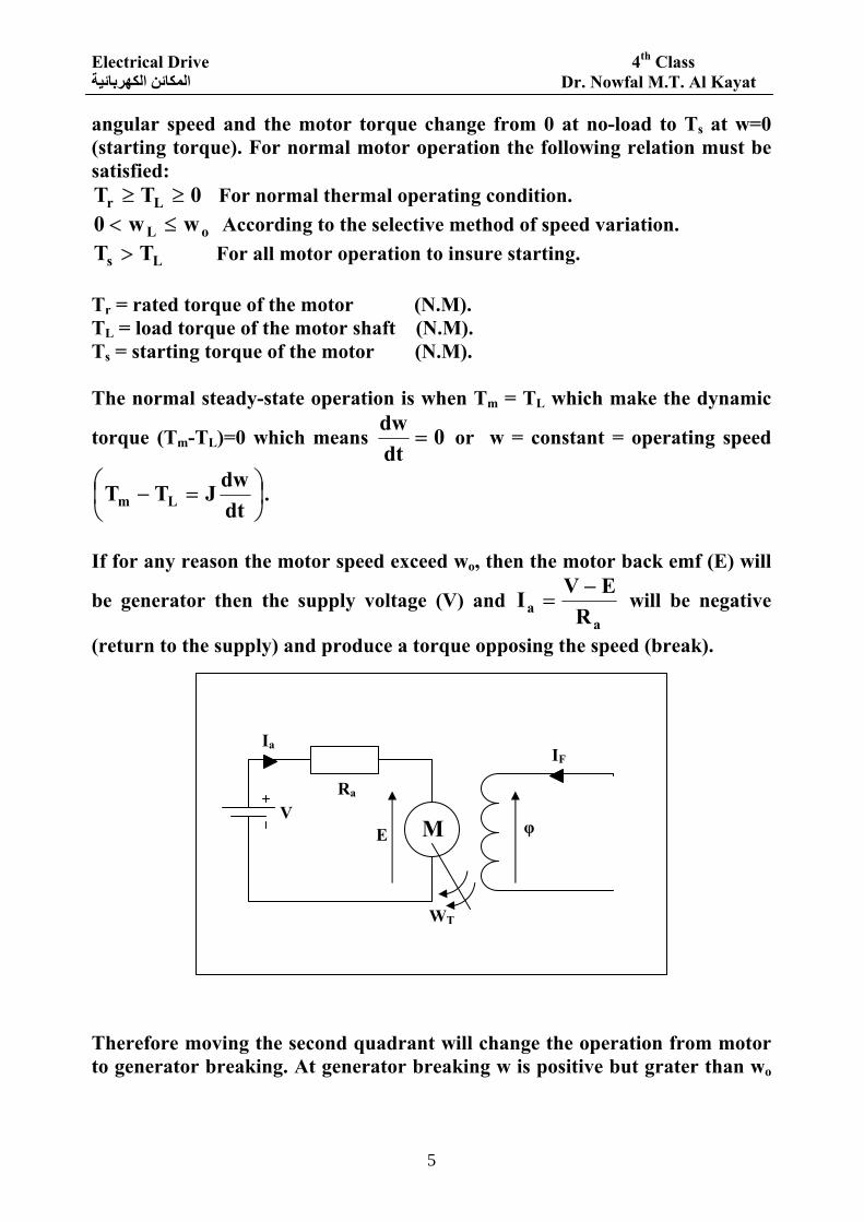
If for any reason the motor speed exceed wo, then the motor back emf (E) will
be generator then the supply voltage (V) and a
a REVI −
= will be negative
(return to the supply) and produce a torque opposing the speed (break). Therefore moving the second quadrant will change the operation from motor to generator breaking. At generator breaking w is positive but grater than wo
φ
Ia
Ra
E V
WT
IF
M
Electrical Drive 4th Class Dr. Nowfal M.T. Al Kayat المكائن الكهربائية
6
and the motor torque oppose the motion (the load torque in the same direction as the motion). At no-load speed wo, E=V, Ia = 0, Tm = 0 (Y-axis) the 3rd quadrant represent also motor operation but in the reverse direction with respect to that in the first-quadrant (i.e. rotation in the clockwise direction and Tm also in the clockwise direction and opposing TL). The 4th quadrant represent break operation by which the motor still taken current from the supply and producing torque (+ve) but opposing the motion. The motion is started by the effect of the load which is grater than Ts (active) and hence the motor move opposite to it's electrical direction causing E to change it's direction.
aa
aa R
EVIR
EVI +=→
−=∴ since E = -ve.
And hence Tm increase as w increase until at certain w: Tm = TL and the load will break at speed = w 0wwo >> .
Torque-speed characteristics (mechanical characteristics) and speed
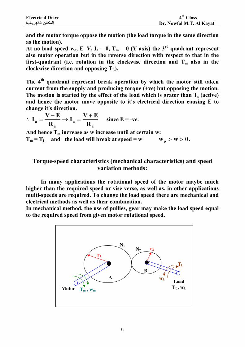
variation methods: In many applications the rotational speed of the motor maybe much higher than the required speed or vise verse, as well as, in other applications multi-speeds are required. To change the load speed there are mechanical and electrical methods as well as their combination. In mechanical method, the use of pullies, gear may make the load speed equal to the required speed from given motor rotational speed.
Tm , wm
r1 r2
N1 N2
A B
Motor Load
TL, wL
TL
wL

Electrical Drive 4th Class Dr. Nowfal M.T. Al Kayat المكائن الكهربائية
7
A simple two gears may have radius r1 and r2 and number of tooth N1 and N2 correspondingly may give the following relationship: Since teeth pitch is the same for both gears: ∴when gear A moves one revolution, (2πr1), gear B must move the same length (2πr1) according to the radius.
i.e. )r2(ir21 21 π=π× where m
L
ww
speed motorspeed loadi == .
2
1
2
1
NN
rr
i ==∴ , mL w iw =
i > 1 if r1 > r2 or N1 > N2. If the gears have the efficiency of 100%: ∴Pin = Pout or Tmwm = TLwL.
iT
ww
TT m
L
mmL ==∴ .
And if the efficiency ≠100% (losses) 1 > ι > 0:
ι=∴ out
inP
P or ι
= LLmm
TwTw
iT
i1T
ww
TT mm
L
mmL
ι=××ι=××ι=∴
If there are multi-stages of gears with Gear ratio = i1, i2, i3, … ( ) m321L w ...iiiw ×××=∴
And ...iii
TT
321
mL ×××= for ideal case.
And ( )
...iiiT...
T321
m321L ×××
×ι×ι×ι= for actual case when nι represent the
efficiency of stage n. When the load is transferred to the motor shaft, and hence it's speed will be wm ∴ the load torque at the motor shaft will be:
LmLLL TwTwP ×=×=
LLm
LL T iT
ww
T ==∴ for ideal case.
ι
= LT i for actual case.
The equivalent system will be as shown:
Motor T\
Tm wm
Electrical Drive 4th Class Dr. Nowfal M.T. Al Kayat المكائن الكهربائية
8
∴steady-state operation when:
ι== L
LmT i
TT .
Electrical Methods: there are many electrical methods which are used to make the load operate at the required speed by changing wm. To select any method the following points are taken into consideration: 1. The direction of speed variation: UP; DOWN; UP and DOWN with respect
to operating speed at natural characteristics. 2. The dynamic range of speed variation, i.e. the possible ratio of maximum to
minimum speed achieved
D = dynamic range of speed = min
m
ww
.
wmin is taken to be at least 10% of rated speed. 3. The stiffness coefficient of mechanical characteristics (β ) which is equal to:
dwdt
−=β . This factor represents the sensitivity of the motor to the load
variation. Ideal motor must keep constant speed when it's load changes, i.e. ∞=β and as this factor decrease it means the motor will be much
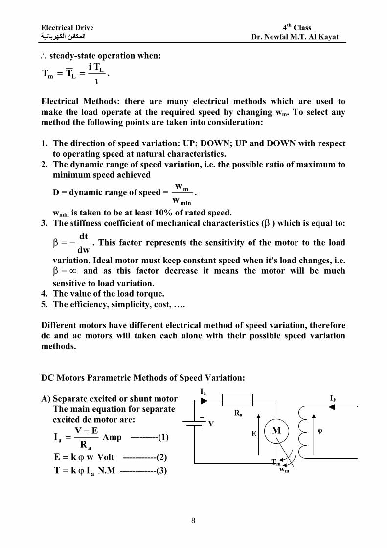
sensitive to load variation. 4. The value of the load torque. 5. The efficiency, simplicity, cost, …. Different motors have different electrical method of speed variation, therefore dc and ac motors will taken each alone with their possible speed variation methods. DC Motors Parametric Methods of Speed Variation: A) Separate excited or shunt motor
The main equation for separate excited dc motor are:
aa R
EVI −= Amp ---------(1)
w kE ϕ= Volt -----------(2)
aI kT ϕ= N.M ------------(3)
φ
Ia
Ra
E V
Tm
IF
wm
M
Electrical Drive 4th Class Dr. Nowfal M.T. Al Kayat المكائن الكهربائية
9
a2ZP.constkπ
==
Where: Z = Conductors / Armature. P = No. of poles. a = No of parallel paths. a = 2 for wave and a = P for lap. The mechanical characteristics (w=f(t)) can be found from equations 1,2 and 3 as:
( )T
kR
kVW 2
a
ϕ−
ϕ= -------------(4)
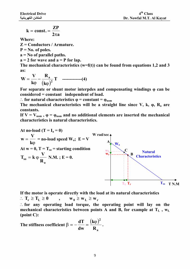
For separate or shunt motor interpdes and compensating windings φ can be considered = constant independent of load. ∴for natural characteristics φ = constant = φnom The mechanical characteristics will be a straight line since V, k, φ, Ra are constants. If V = Vnom , φ = φnom and no additional elements are inserted the mechanical characteristics is natural characteristics. At no-load (T = Ia = 0)
ϕ=
kVw = no-load speed Wo; E = V
At w = 0, T = Tso = starting condition
aso R
V kT ϕ= N.M. ; E = 0.
If the motor is operate directly with the load at its natural characteristics rL0Lr www , 0TT ≥≥≥≥∴
∴for any operating load torque, the operating point will lay on the mechanical characteristics between points A and B, for example at TL , wL (point C):
The stiffness coefficient ( )
a
2
Rk
dwdT ϕ
=−=β .
. .
.
C
Wo A
B
Tr TL Tso T N.M
Natural Characteristics
W rad/sec
wL wr
Electrical Drive 4th Class Dr. Nowfal M.T. Al Kayat المكائن الكهربائية
10
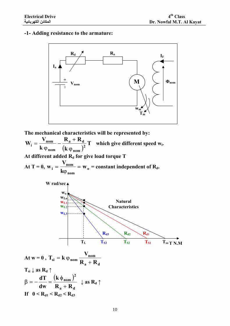
-1- Adding resistance to the armature: The mechanical characteristics will be represented by:
( )T
kRR
kV
W 2nom
da
nom
nomi
ϕ
+−
ϕ= which give different speed wi.
At different added Rd for give load torque T
At T = 0, onom
nomi w
kV
w =ϕ
= = constant independent of Rd.
At w = 0 , da
nomnomsi RR
V kT
+ϕ=
Tsi ↓ as Rd ↑ ( )
da
2nom
RR k
dwdT
+φ
=−=β ↓ as Rd ↑
If 0 < Rd1 < Rd2 < Rd3
Ia
Rd Ra IF
Φnom
Tm wm
Vnom
T N.M
Natural Characteristics
W rad/sec
. . .
.
Tso TS1 TS2 TS3 TL
wo .
Rd1 Rd2 Rd3
wL3
wL2 wL1
wLo
M
Electrical Drive 4th Class Dr. Nowfal M.T. Al Kayat المكائن الكهربائية
11
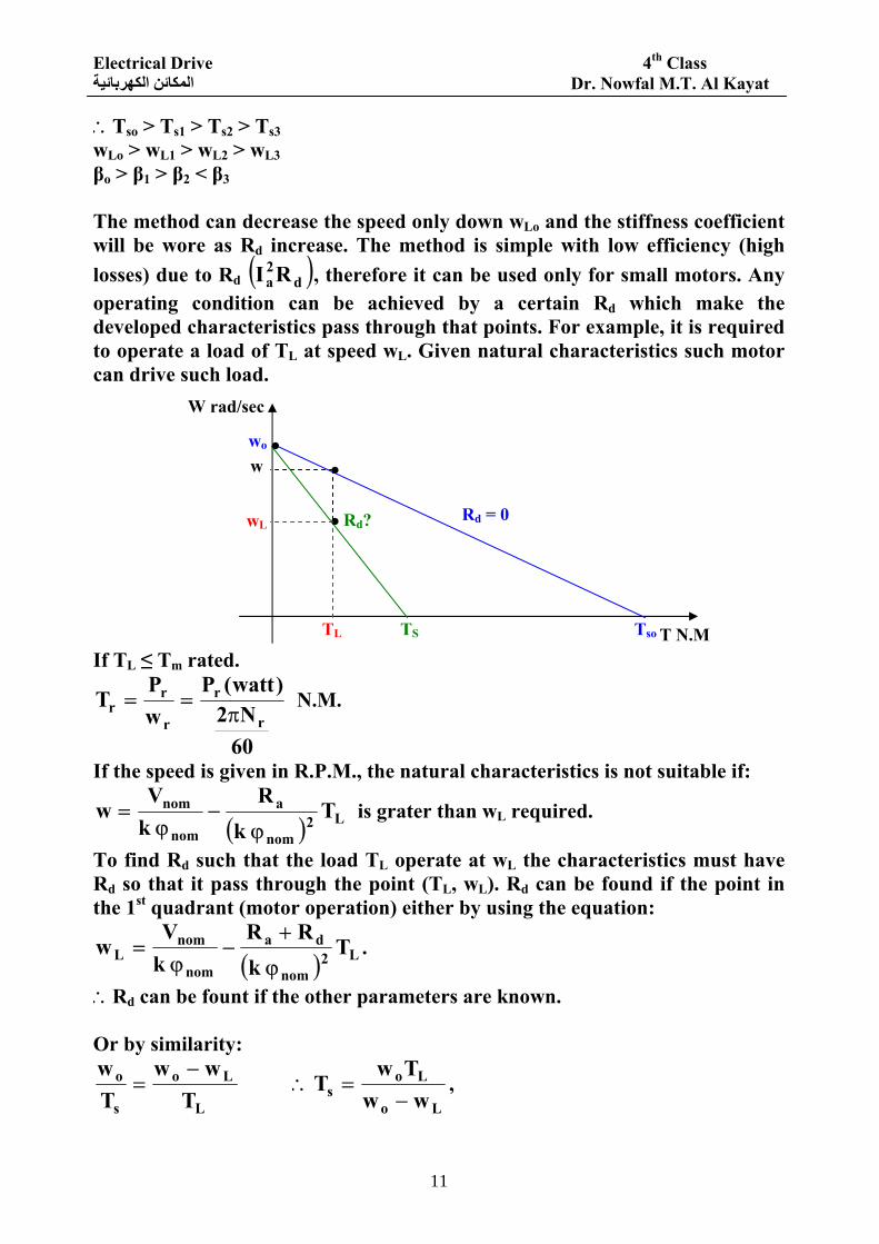
∴Tso > Ts1 > Ts2 > Ts3 wLo > wL1 > wL2 > wL3 βo > β1 > β2 < β3 The method can decrease the speed only down wLo and the stiffness coefficient will be wore as Rd increase. The method is simple with low efficiency (high losses) due to Rd ( )d
2aRI , therefore it can be used only for small motors. Any
operating condition can be achieved by a certain Rd which make the developed characteristics pass through that points. For example, it is required to operate a load of TL at speed wL. Given natural characteristics such motor can drive such load. If TL ≤ Tm rated.
60N2
)watt(PwP
Tr
r
r
rr π
== N.M.
If the speed is given in R.P.M., the natural characteristics is not suitable if:
( ) L2nom
a
nom
nom T k
R kV
wϕ
−ϕ
= is grater than wL required.
To find Rd such that the load TL operate at wL the characteristics must have Rd so that it pass through the point (TL, wL). Rd can be found if the point in the 1st quadrant (motor operation) either by using the equation:
( ) L2nom
da
nom
nomL T
kRR
kV
wϕ
+−
ϕ= .
∴Rd can be fount if the other parameters are known. Or by similarity:
L
Lo
s
o
Tww
Tw −
= Lo
Los ww
TwT
−=∴ ,
T N.M
Rd = 0
W rad/sec
.
.
Tso TS TL
wo .
Rd? wL
w
Electrical Drive 4th Class Dr. Nowfal M.T. Al Kayat المكائن الكهربائية
12
da
nomnoms RR
V kT
+ϕ=Q ∴ Rd is found.
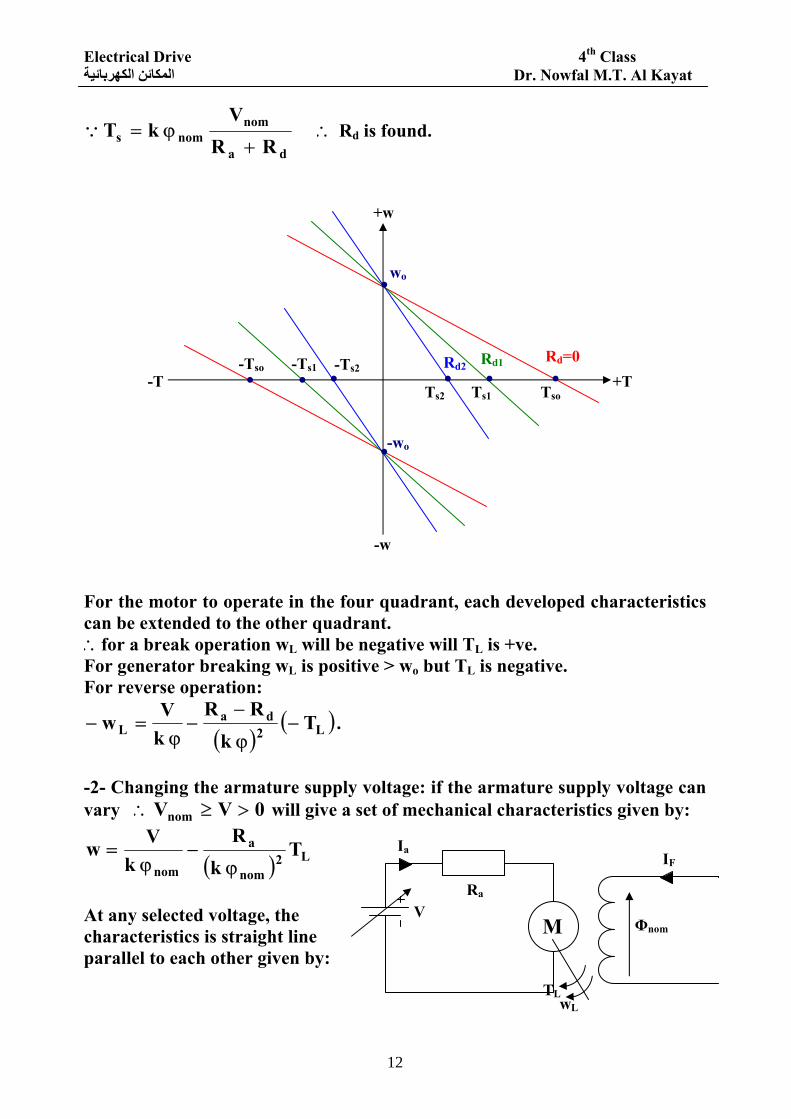
For the motor to operate in the four quadrant, each developed characteristics can be extended to the other quadrant. ∴for a break operation wL will be negative will TL is +ve. For generator breaking wL is positive > wo but TL is negative. For reverse operation:
( )( )L2
daL T
kRR
kVw −
ϕ
−−
ϕ=− .
-2- Changing the armature supply voltage: if the armature supply voltage can vary 0VVnom >≥∴ will give a set of mechanical characteristics given by:
( ) L2nom
a
nomT
kR
kVw
ϕ−
ϕ=
At any selected voltage, the characteristics is straight line parallel to each other given by:
wo
+w
-w
+T -T
-wo
.
.
.
. . Rd2 Rd=0 Rd1 . . . Ts2
-Tso -Ts1 -Ts2
Ts1 Tso
Φnom
Ia
Ra V
TL
IF
wL
M
Electrical Drive 4th Class Dr. Nowfal M.T. Al Kayat المكائن الكهربائية
13
nom
ioi k
Vw
ϕ= , nom
a
isi k
RV
T ϕ=
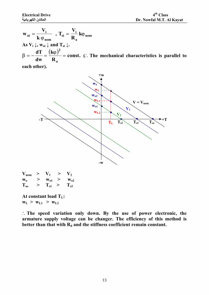
As Vi ↓, woi ↓ and Tsi ↓. ( )
.constRk
dwdT
a
2
=ϕ
=−=β (∴The mechanical characteristics is parallel to
each other). Vnom > V1 > V2 wo > wo1 > wo2 Tso > Ts1 > Ts2 At constant load TL: wL > wL1 > wL2 ∴The speed variation only down. By the use of power electronic, the armature supply voltage can be changer. The efficiency of this method is better than that with Rd and the stiffness coefficient remain constant.
wo
+w
-w
+T -T
..
. . . wo1 .wo2 .
.
.wL
wL1
wL2
TL Ts2 Ts1 Tso
V1 V = Vnom
V2
Electrical Drive 4th Class Dr. Nowfal M.T. Al Kayat المكائن الكهربائية
14
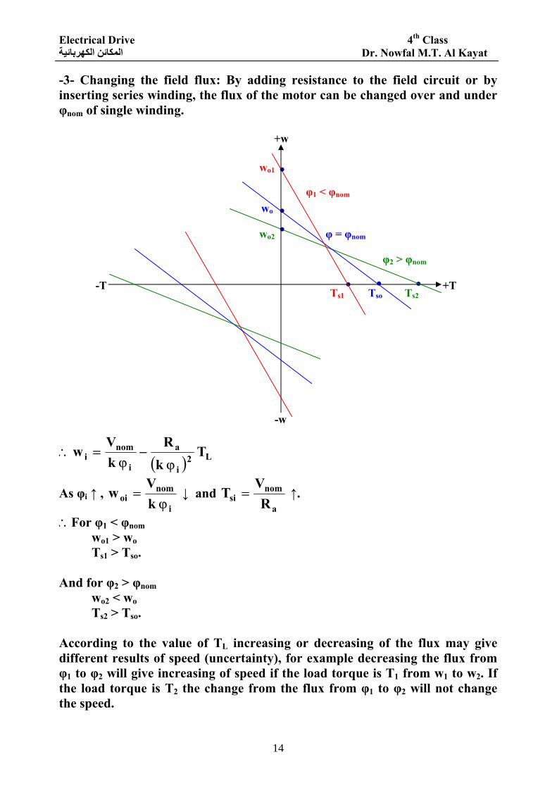
-3- Changing the field flux: By adding resistance to the field circuit or by inserting series winding, the flux of the motor can be changed over and under φnom of single winding.
( ) L2i
a
i
nomi T
kR
kV
wϕ
−ϕ
=∴
As φi ↑ , i
nomoi k
Vw
ϕ= ↓ and
a
nomsi R
VT = ↑.
∴For φ1 < φnom wo1 > wo Ts1 > Tso. And for φ2 > φnom wo2 < wo Ts2 > Tso. According to the value of TL increasing or decreasing of the flux may give different results of speed (uncertainty), for example decreasing the flux from φ1 to φ2 will give increasing of speed if the load torque is T1 from w1 to w2. If the load torque is T2 the change from the flux from φ1 to φ2 will not change the speed.
Ts1
+w
-w
+T -T . . .
.
.
.
wo1
wo
wo2
Tso Ts2
φ1 < φnom
φ = φnom
φ2 > φnom

Electrical Drive 4th Class Dr. Nowfal M.T. Al Kayat المكائن الكهربائية
15
At load torque T3 the changing from the flux from φ1 to φ2 will decrease the speed from w3 to w4 as shown in the diagram.
The method affect the stiffness coefficient ( )
a
2i
R k ϕ
=β ↓ as φi ↓ but the
method is more efficient than that with Rd in armature. Example: A separate excited, 3KW, 150 Volt, 1600 R.P.M, dc motor has an armature resistance = 1 Ω is to be used in drive through a reducer of
10NN
L
m = . If the load torque is 150 N.M find the required Rd added to the
armature to operate the load at 1 rad/sec? What voltage reduction is used for such operation if no Rd is added? Solution:
55.1676016002
60n 2
w rr =
×π=
π= rad/sec.
1510
150T\L == N.M.
10101w \L =×= rad/sec.
9.1755.167
103wP
T3
r
rmr =
×== N.M (such motor can drive the load 15 N.M)
w
T
φ2
φ1
T1 T2 T3
w2
w1
w3
w4
Electrical Drive 4th Class Dr. Nowfal M.T. Al Kayat المكائن الكهربائية
16
For natural characteristics:
( ) r2a
r T kR
kVw
ϕ−
ϕ=
( )9.17
k1
k15055.167 2 ×ϕ
−ϕ
=∴
( ) ( ) 09.17k150k55.167 2 =+ϕ−ϕ∴
55.16724.102150
55.16729.1755.1674150150k
2
×±
=×
××−±=ϕ
∴Either 753.055.1672
102.4150k =×+
=ϕ or 142.055.1672
4.102150k =×−
=ϕ
ϕ=∴
kVwo , either 2.199
753.0150wo == rad/sec or
1056142.0
150wo == rad/sec.
By neglect very far from wr. 753.0k =ϕ∴ .
To find Rd required
( )15
753.0R1
2.19910 2d ×
+−=∴
( ) 2.189102.19945.26 R1 d =−=+
Ω=∴==+∴ 153.6R 153.745.262.189R1 dd .
For Rd = 0 → ( )
15753.01
753.0V10 2 ×−=
45.3645.2610V33.1 =+=
4.2733.145.36V ==∴ Volt.
∴The reduction of supply voltage = 150 – 27.4 = 122.6 Volt.
Electrical Drive 4th Class Dr. Nowfal M.T. Al Kayat المكائن الكهربائية
17
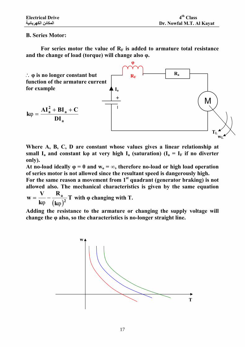
B. Series Motor: For series motor the value of RF is added to armature total resistance and the change of load (torque) will change also φ. ∴φ is no longer constant but function of the armature current for example
a
a2a
DICBIAI
k++
=ϕ
Where A, B, C, D are constant whose values gives a linear relationship at small Ia and constant kφ at very high Ia (saturation) (Ia = IF if no diverter only). At no-load ideally φ = 0 and wo = ∞, therefore no-load or high load operation of series motor is not allowed since the resultant speed is dangerously high. For the same reason a movement from 1st quadrant (generator braking) is not allowed also. The mechanical characteristics is given by the same equation
( )T
kR
kVw 2
a
ϕ−
ϕ= with φ changing with T.
Adding the resistance to the armature or changing the supply voltage will change the φ also, so the characteristics is no-longer straight line.
φ
Ia
RF Ra
TL wL
w
T
Electrical Drive 4th Class Dr. Nowfal M.T. Al Kayat المكائن الكهربائية
18
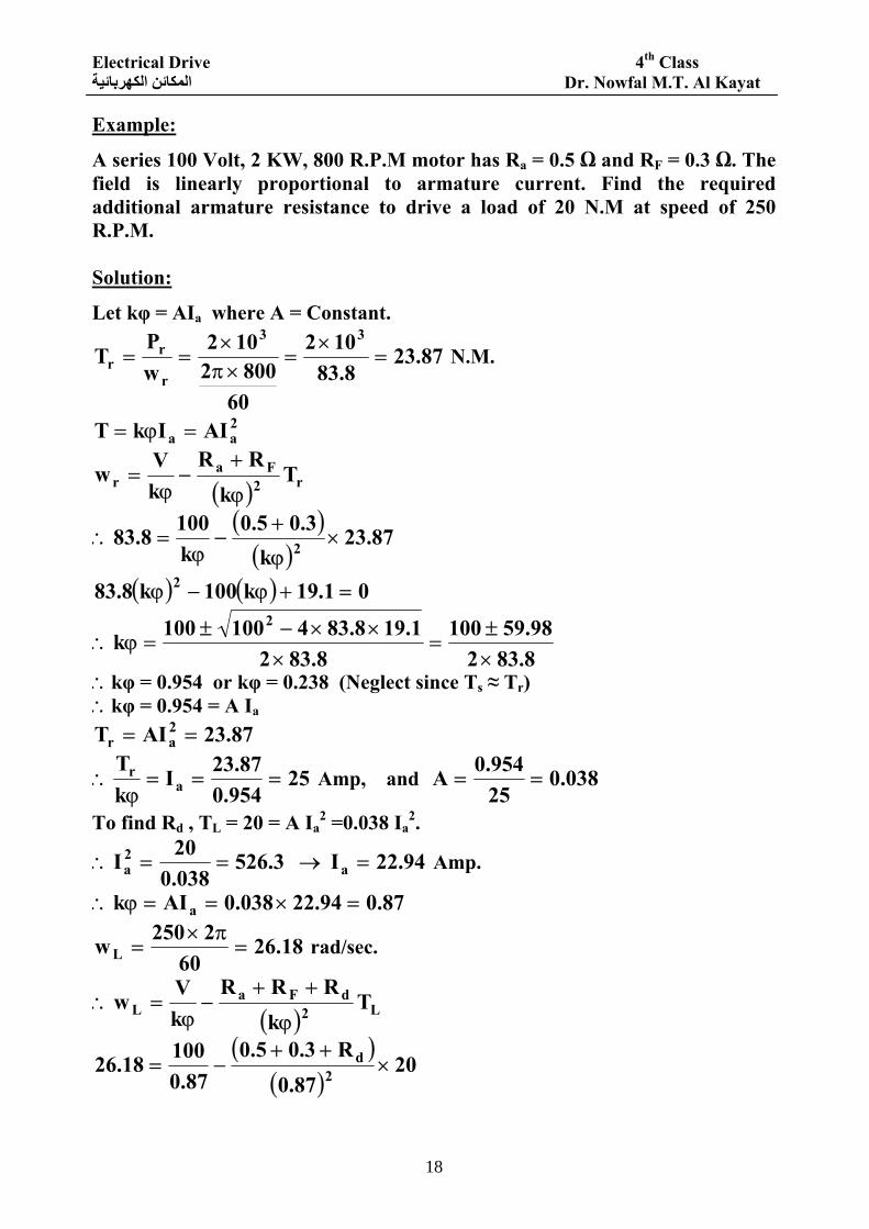
Example:
A series 100 Volt, 2 KW, 800 R.P.M motor has Ra = 0.5 Ω and RF = 0.3 Ω. The field is linearly proportional to armature current. Find the required additional armature resistance to drive a load of 20 N.M at speed of 250 R.P.M. Solution:
Let kφ = AIa where A = Constant.
87.238.83
102
608002
102wP
T33
r
rr =
×=
×π×
== N.M.
2aa AIIkT =ϕ=
( ) r2Fa
r Tk
RRkVw
ϕ
+−
ϕ=
( )( )
87.23k
3.05.0k1008.83 2 ×
ϕ
+−
ϕ=∴
( ) ( ) 01.19k100k8.83 2 =+ϕ−ϕ
8.83298.59100
8.8321.198.834100100k
2
×±
=×
××−±=ϕ∴
∴kφ = 0.954 or kφ = 0.238 (Neglect since Ts ≈ Tr) ∴kφ = 0.954 = A Ia
87.23AIT 2ar ==
25954.087.23I
kT
ar ===ϕ
∴ Amp, and 038.025954.0A ==
To find Rd , TL = 20 = A Ia2 =0.038 Ia
2.
94.22I 3.526038.020I a
2a =→==∴ Amp.
87.094.22038.0AIk a =×==ϕ∴
18.2660
2250wL =π×
= rad/sec.
( ) L2dFa
L Tk
RRRkVw
ϕ
++−
ϕ=∴
( )( )
2087.0
R3.05.087.0
10018.26 2d ×
++−=
Electrical Drive 4th Class Dr. Nowfal M.T. Al Kayat المكائن الكهربائية
19
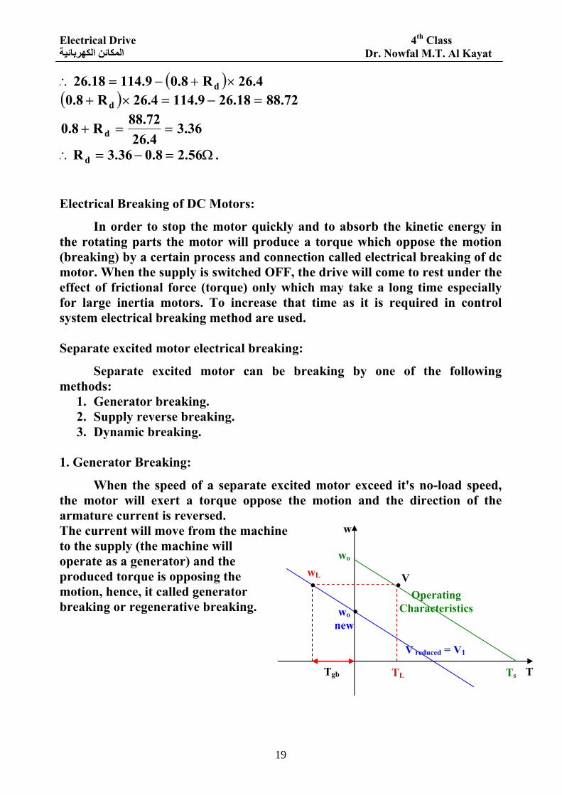
( ) 4.26R8.09.11418.26 d ×+−=∴ ( ) 72.8818.269.1144.26R8.0 d =−=×+
36.34.26
72.88R8.0 d ==+
Ω=−=∴ 56.28.036.3R d . Electrical Breaking of DC Motors:
In order to stop the motor quickly and to absorb the kinetic energy in the rotating parts the motor will produce a torque which oppose the motion (breaking) by a certain process and connection called electrical breaking of dc motor. When the supply is switched OFF, the drive will come to rest under the effect of frictional force (torque) only which may take a long time especially for large inertia motors. To increase that time as it is required in control system electrical breaking method are used. Separate excited motor electrical breaking:
Separate excited motor can be breaking by one of the following methods:
1. Generator breaking. 2. Supply reverse breaking. 3. Dynamic breaking.
1. Generator Breaking:
When the speed of a separate excited motor exceed it's no-load speed, the motor will exert a torque oppose the motion and the direction of the armature current is reversed. The current will move from the machine to the supply (the machine will operate as a generator) and the produced torque is opposing the motion, hence, it called generator breaking or regenerative breaking.
. . wo
V
TL Tgb
. wo new
Ts T
w
wL
Operating Characteristics
V reduced = V1
Electrical Drive 4th Class Dr. Nowfal M.T. Al Kayat المكائن الكهربائية
20
Suppose a motor drive a load TL at speed wL according to the mechanical characteristics as shown in the figure. If the voltage is reduced or φ is increase such that the new mechanical characteristics has wo < wL as shown. Then at t = 0 when V is changed the motor will produced a torque = Tgb opposing the motion. As w reduced from wL to (wo new ) this torque will change from Tgb to zero. For the operating characteristics wo > wL and the machine operate as motor with E = (kφwL) is less than V, the armature current is
aaa r
wkvR
EVI ϕ−=
−= from the supply to the motor producing a torque =
kφIa = ⎟⎟⎠
⎞⎜⎜⎝
⎛ ϕ−ϕ
aRwkV k in the same direction as that of the speed (motor
operation).
When the voltage V is changed to V1 , V1 < V such that L1
newo wkV
w <ϕ
= .
a
L1
a
1newa R
wkVR
EVI
ϕ−=
−=∴ = -ve since kφwo new = V1.
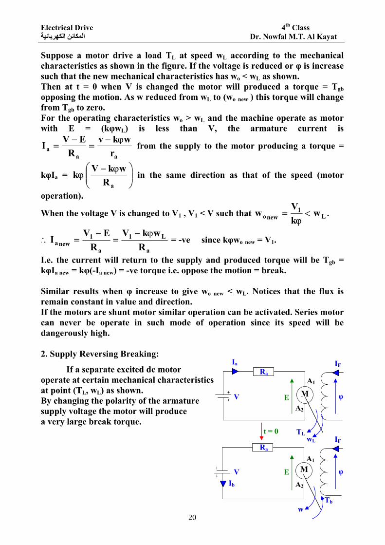
I.e. the current will return to the supply and produced torque will be Tgb = kφIa new = kφ(-Ia new) = -ve torque i.e. oppose the motion = break. Similar results when φ increase to give wo new < wL. Notices that the flux is remain constant in value and direction. If the motors are shunt motor similar operation can be activated. Series motor can never be operate in such mode of operation since its speed will be dangerously high. 2. Supply Reversing Breaking:
If a separate excited dc motor operate at certain mechanical characteristics at point (TL, wL) as shown. By changing the polarity of the armature supply voltage the motor will produce a very large break torque.
V
V
Ia
Ib
E
E
Ra
Ra
φ
φ
IF
IF t = 0 TL
wL
w Tb
A1
A2
A2
A1
M
M
Electrical Drive 4th Class Dr. Nowfal M.T. Al Kayat المكائن الكهربائية
21
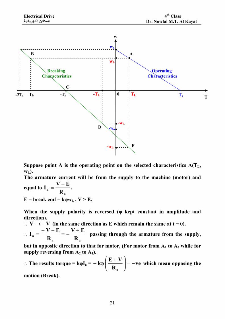
Suppose point A is the operating point on the selected characteristics A(TL, wL). The armature current will be from the supply to the machine (motor) and
equal to a
a REVI −
= .
E = break emf = kφwL , V > E. When the supply polarity is reversed (φ kept constant in amplitude and direction).
VV −→∴ (in the same direction as E which remain the same at t = 0).
aaa R
EVR
EVI +−=
−−=∴ passing through the armature from the supply,
but in opposite direction to that for motor, (For motor from A1 to A2 while for supply reversing from A2 to A1).
∴The results torque = kφIa = veR
VE ka
−=⎟⎟⎠
⎞⎜⎜⎝
⎛ +ϕ− which mean opposing the
motion (Break).
.
w
T
wo
wL
Ts TL
D
.
.
. A .
-wL . -wo
. -wL F
. . C
B
0 -TL -Ts Tb -2Ts
Operating Characteristics
Breaking Characteristics
Electrical Drive 4th Class Dr. Nowfal M.T. Al Kayat المكائن الكهربائية
22
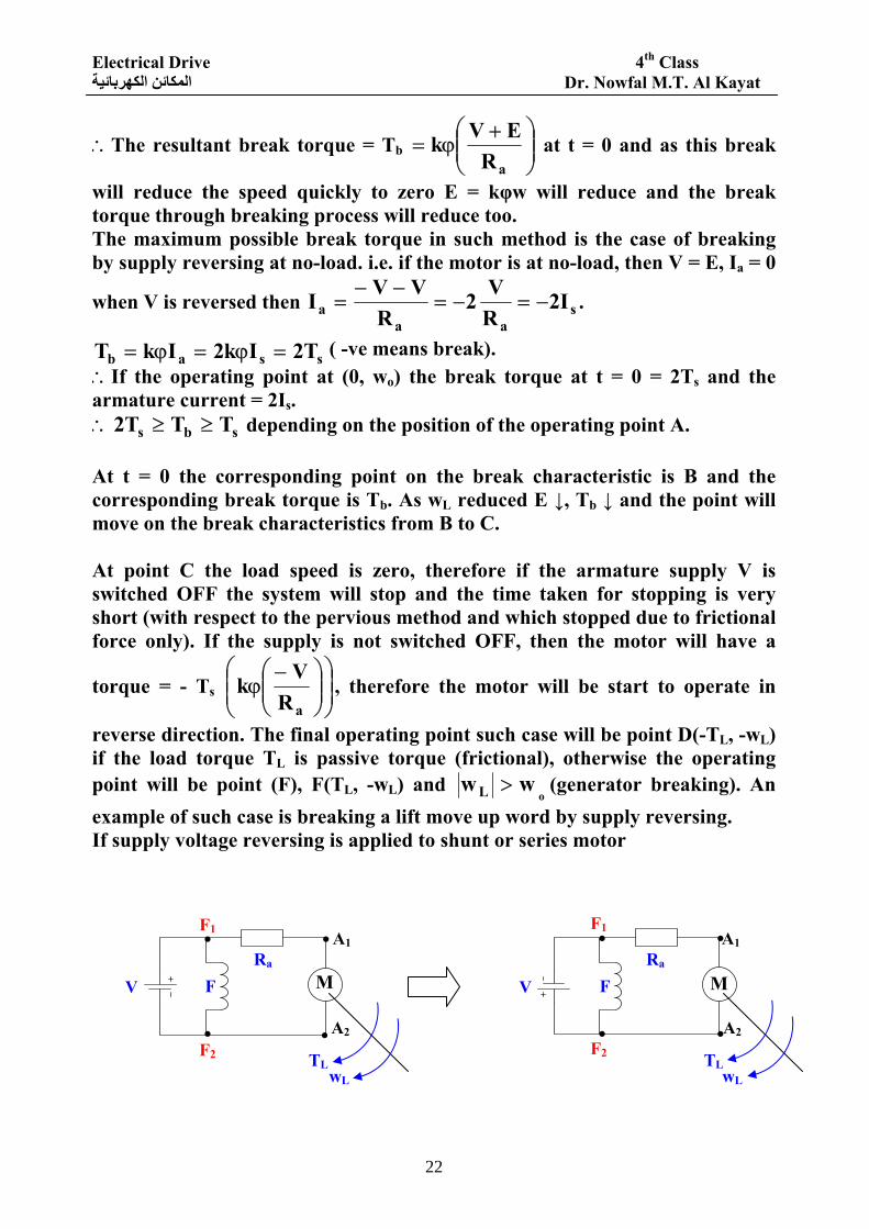
∴The resultant break torque = Tb ⎟⎟⎠
⎞⎜⎜⎝
⎛ +ϕ=
aREVk at t = 0 and as this break
will reduce the speed quickly to zero E = kφw will reduce and the break torque through breaking process will reduce too. The maximum possible break torque in such method is the case of breaking by supply reversing at no-load. i.e. if the motor is at no-load, then V = E, Ia = 0
when V is reversed then saa
a I2RV 2
RVVI −=−=
−−= .
ssab T2Ik2IkT =ϕ=ϕ= ( -ve means break). ∴If the operating point at (0, wo) the break torque at t = 0 = 2Ts and the armature current = 2Is.
sbs TTT2 ≥≥∴ depending on the position of the operating point A. At t = 0 the corresponding point on the break characteristic is B and the corresponding break torque is Tb. As wL reduced E ↓, Tb ↓ and the point will move on the break characteristics from B to C. At point C the load speed is zero, therefore if the armature supply V is switched OFF the system will stop and the time taken for stopping is very short (with respect to the pervious method and which stopped due to frictional force only). If the supply is not switched OFF, then the motor will have a
torque = - Ts ⎟⎟⎠
⎞⎜⎜⎝
⎛⎟⎟⎠
⎞⎜⎜⎝
⎛ −ϕ
aRVk , therefore the motor will be start to operate in
reverse direction. The final operating point such case will be point D(-TL, -wL) if the load torque TL is passive torque (frictional), otherwise the operating point will be point (F), F(TL, -wL) and
owwL > (generator breaking). An
example of such case is breaking a lift move up word by supply reversing. If supply voltage reversing is applied to shunt or series motor
.
.
.
.
.
. .
.
TL TL wL wL
V V
F1 F1
F2 F2
Ra Ra F F
A1
A2 A2
A1
M M
Electrical Drive 4th Class Dr. Nowfal M.T. Al Kayat المكائن الكهربائية
23
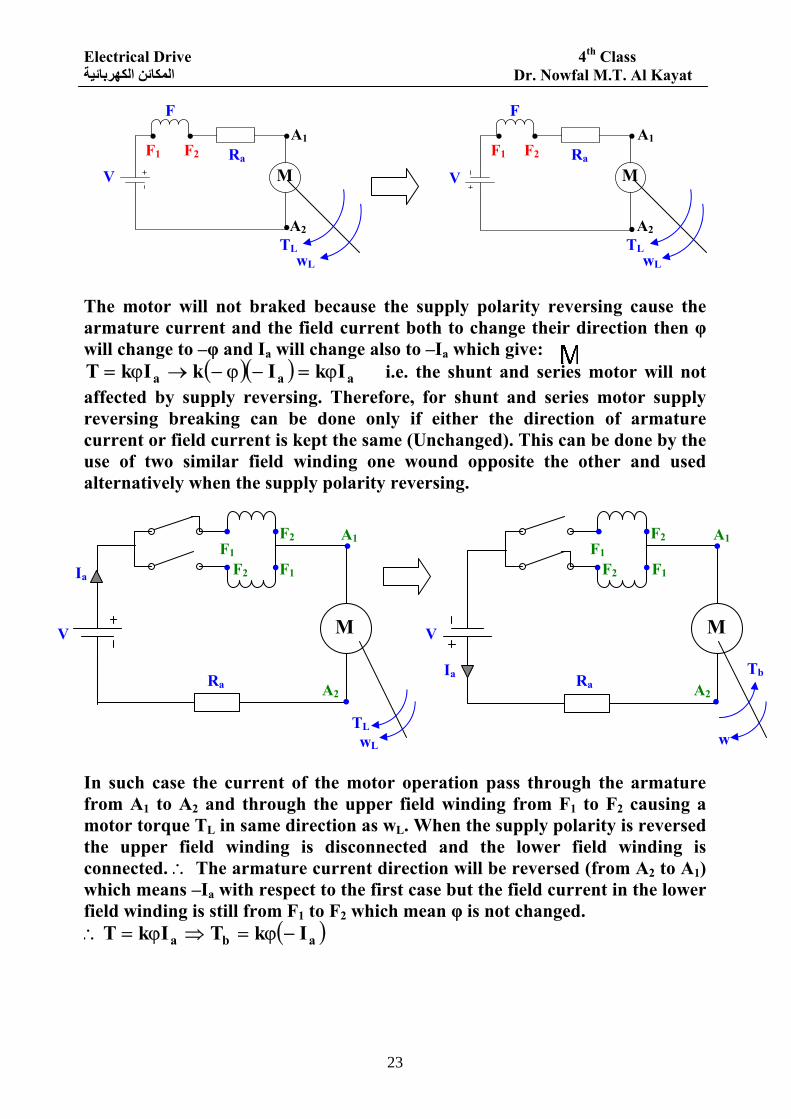
The motor will not braked because the supply polarity reversing cause the armature current and the field current both to change their direction then φ will change to –φ and Ia will change also to –Ia which give:
( )( ) aaa IkIkIkT ϕ=−ϕ−→ϕ= i.e. the shunt and series motor will not affected by supply reversing. Therefore, for shunt and series motor supply reversing breaking can be done only if either the direction of armature current or field current is kept the same (Unchanged). This can be done by the use of two similar field winding one wound opposite the other and used alternatively when the supply polarity reversing. In such case the current of the motor operation pass through the armature from A1 to A2 and through the upper field winding from F1 to F2 causing a motor torque TL in same direction as wL. When the supply polarity is reversed the upper field winding is disconnected and the lower field winding is connected. ∴ The armature current direction will be reversed (from A2 to A1) which means –Ia with respect to the first case but the field current in the lower field winding is still from F1 to F2 which mean φ is not changed.
( )aba IkTIkT −ϕ=⇒ϕ=∴
.
.
.
.
. . . .
TL TL wL wL
V V
F1 F1 F2 F2 Ra Ra
F F A1
A2 A2
A1
V
Ia
Ia
V
Ra Ra
TL wL w
Tb
. . . .
. . . . . .
. .
F1 F1 F2
F1 F1
F2
F2 F2
A1 A1
A2 A2
M M
M M
Electrical Drive 4th Class Dr. Nowfal M.T. Al Kayat المكائن الكهربائية
24
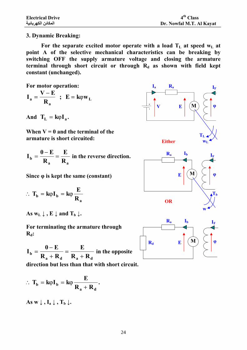
3. Dynamic Breaking:
For the separate excited motor operate with a load TL at speed wL at point A of the selective mechanical characteristics can be breaking by switching OFF the supply armature voltage and closing the armature terminal through short circuit or through Rd as shown with field kept constant (unchanged). For motor operation:
La
a wkE ; R
EVI ϕ=−
=
And aL IkT ϕ= . When V = 0 and the terminal of the armature is short circuited:
aab R
ER
E0I =−
= in the reverse direction.
Since φ is kept the same (constant)
abb R
EkIkT ϕ=ϕ=∴
As wL ↓ , E ↓ and Tb ↓. For terminating the armature through Rd:
dadab RR
ERRE0I
+=
+−
= in the opposite
direction but less than that with short circuit.
dabb RR
EkIkT+
ϕ=ϕ=∴ .
As w ↓ , Ia ↓ , Tb ↓.
Either
OR
Rd E
E
E V
Ia Ra
Ra
Ra
Ib
Ib IF
IF
IF
φ
φ
φ
Tb
TL wL
w
M
M
M
Electrical Drive 4th Class Dr. Nowfal M.T. Al Kayat المكائن الكهربائية
25
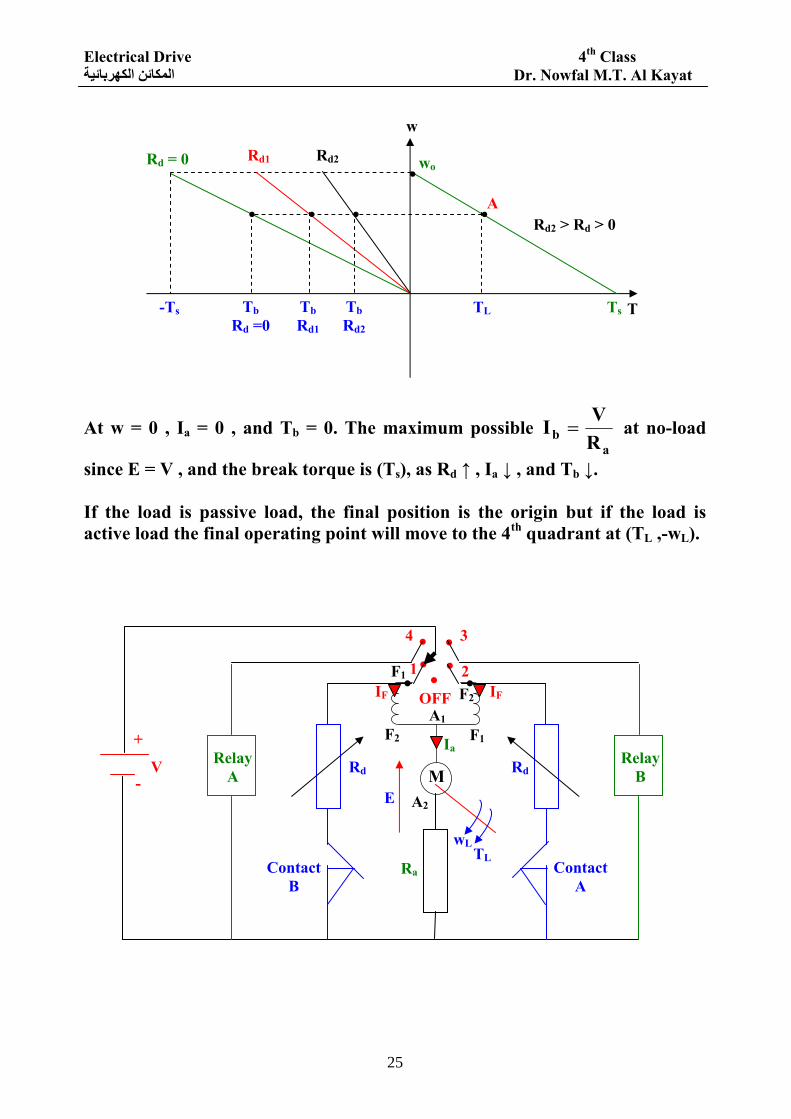
At w = 0 , Ia = 0 , and Tb = 0. The maximum possible a
b RVI = at no-load
since E = V , and the break torque is (Ts), as Rd ↑ , Ia ↓ , and Tb ↓. If the load is passive load, the final position is the origin but if the load is active load the final operating point will move to the 4th quadrant at (TL ,-wL).
A
w
T
. . . .
Ts TL Tb Rd2
Tb Rd1
Tb Rd =0
-Ts
wo . Rd2 Rd1 Rd = 0
Rd2 > Rd > 0
. . . . . . . +
V -
Relay A
Relay B Rd Rd
Contact A
Contact B
IF IF
1
OFF
2
3 4
F2 F1
F1 F2 Ia
A1
A2
Ra
wL TL
E
M
Electrical Drive 4th Class Dr. Nowfal M.T. Al Kayat المكائن الكهربائية
26
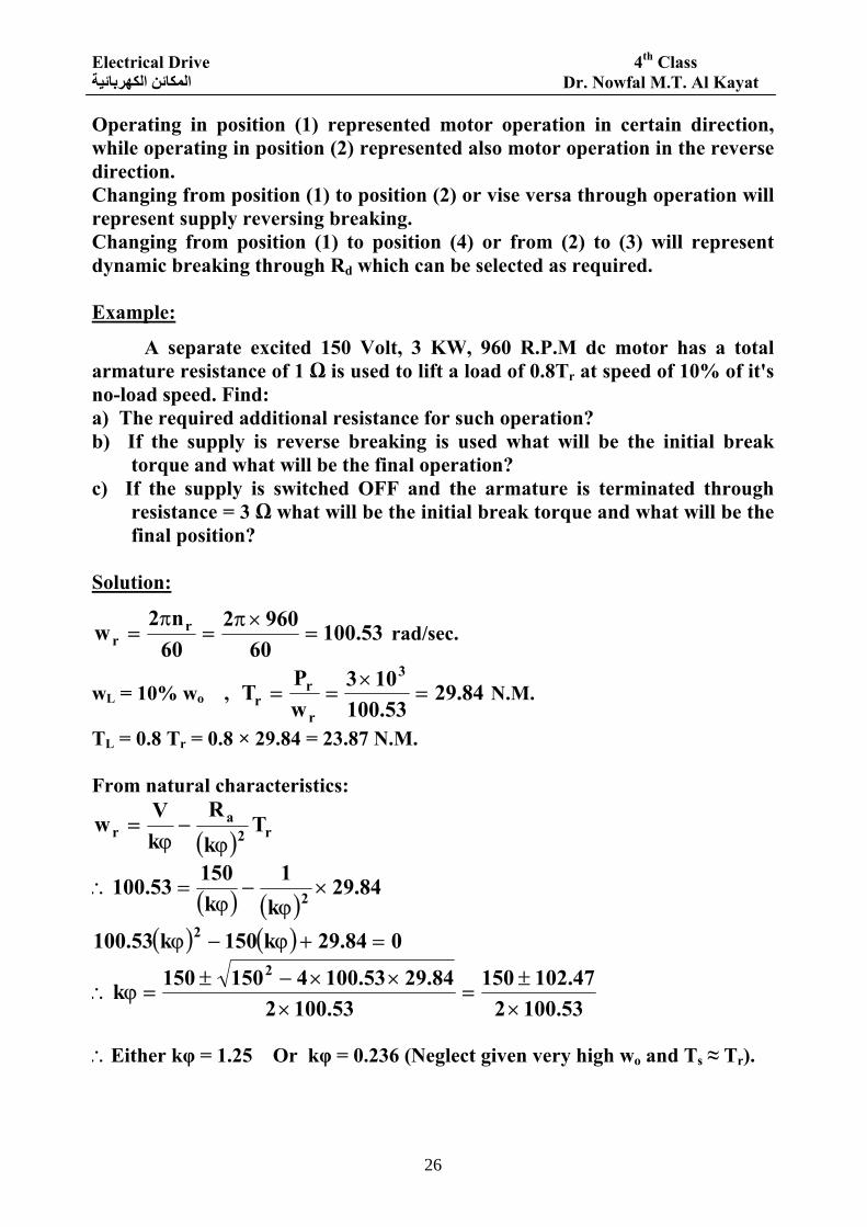
Operating in position (1) represented motor operation in certain direction, while operating in position (2) represented also motor operation in the reverse direction. Changing from position (1) to position (2) or vise versa through operation will represent supply reversing breaking. Changing from position (1) to position (4) or from (2) to (3) will represent dynamic breaking through Rd which can be selected as required. Example:
A separate excited 150 Volt, 3 KW, 960 R.P.M dc motor has a total armature resistance of 1 Ω is used to lift a load of 0.8Tr at speed of 10% of it's no-load speed. Find: a) The required additional resistance for such operation? b) If the supply is reverse breaking is used what will be the initial break
torque and what will be the final operation? c) If the supply is switched OFF and the armature is terminated through
resistance = 3 Ω what will be the initial break torque and what will be the final position?
Solution:
53.10060
960260n2
w rr =
×π=
π= rad/sec.
wL = 10% wo , 84.2953.100
103wP
T3
r
rr =
×== N.M.
TL = 0.8 Tr = 0.8 × 29.84 = 23.87 N.M. From natural characteristics:
( ) r2a
r TkR
kVw
ϕ−
ϕ=
( ) ( )84.29
k1
k15053.100 2 ×ϕ
−ϕ
=∴
( ) ( ) 084.29k150k53.100 2 =+ϕ−ϕ
53.100247.102150
53.100284.2953.1004150150k
2
×±
=×
××−±=ϕ∴
∴Either kφ = 1.25 Or kφ = 0.236 (Neglect given very high wo and Ts ≈ Tr).
Electrical Drive 4th Class Dr. Nowfal M.T. Al Kayat المكائن الكهربائية
27
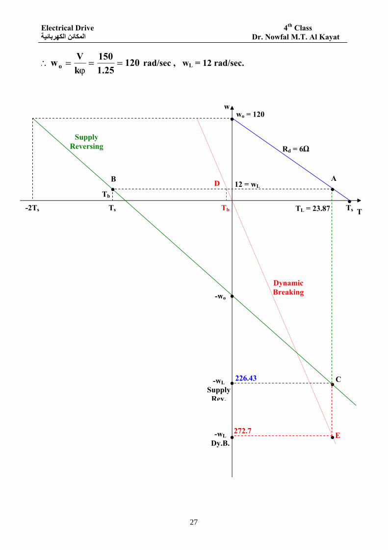
12025.1
150kVwo ==ϕ
=∴ rad/sec , wL = 12 rad/sec.
.
.
wo = 120 .
Tb
w
T
12 = wL A . . B D
Ts -2Ts
Tb
Rd = 6Ω
. Ts TL = 23.87
C
-wL Dy.B.
.
.
E 272.7
226.43 -wL Supply
Rev.
-wo . Dynamic Breaking
Supply Reversing
Electrical Drive 4th Class Dr. Nowfal M.T. Al Kayat المكائن الكهربائية
28
To find Rd:
( ) L2da
L Tk
RRkVw
ϕ
+−
ϕ=
( )87.23
25.1R1
25.115012 2
d ×+
−=∴
( ) 27.15R112120 d ×+=−
Ω==+ 727.15
108R1 d
Ω=−=∴ 617Rd For supply reversing the initial breaking is represented by point B (Tb)
57.237
1225.1150tREVI
ab =
×−−=
−−= (In opposite direction to that for
motor operation). M.N46.2957.2325.1IkT bb =×=ϕ=∴
Since the load is the potential load, therefore, final operating position will represented by point C (General breaking for reverse operation).
( ) ( )93.22687.23
25.17120T
ktR
kVw 2L2
aL =×+=
ϕ+
ϕ=−∴ rad/sec.
For dynamic breaking through 3 Ω:
.Amp 5.137
1225.13tR
E0Ia
b =+×−
=+
−= in the opposite direction to motor
operation.
N.M. 875.15.125.1IlT bb =×=ϕ=∴ (Point D). The final operating position will also be generator breaking (pot. load).
( ) ( )7.27287.23
25.110120T
k3tR
kVw 2L2
aL =×+=
ϕ
++
ϕ=−∴ rad/sec Pint (E).


![Tampa, Florida January 12, 2012 Faculty Advisor: Dr. Ali ... · [THESIS PROPOSAL 1ST REVIEW RAFFI KAYAT|STRUCTURAL] January 12, 2012 January 12, 2012 J.. yrd Alzheimer’s enter &](https://img.pdfslide.us/doc/110x75/5b030a857f8b9a4e538bbc06/tampa-florida-january-12-2012-faculty-advisor-dr-ali-thesis-proposal-1st.jpg)


![Computer Programming [Lab Sheet] - الجامعة التكنولوجية · 2018-01-19 · University of Technology Department of Production Engineering and Metallurgy 2010 Computer](https://img.pdfslide.us/doc/110x75/5e7f3ed7ccb982202c2a10c6/computer-programming-lab-sheet-f-2018-01-19.jpg)

![Technical report 1 Raffi Kayat|Structural · 2011-09-23 · [TECHNICAL REPORT 1 RAFFI KAYAT|STRUCTURAL] September 23, 2011 Semptember, 23rd 2011 J.. yrd Alzheimer’s enter & Research](https://img.pdfslide.us/doc/110x75/5e6f53bc3b16a5086937661a/technical-report-1-raffi-kayat-2011-09-23-technical-report-1-raffi-kayatstructural.jpg)