Embed Size (px)
Citation preview
7
Electrical Disturbances from High Speed Railway Environment to Existing Services
Juan de Dios Sanz-Bobi, Jorge Garzón-Núñez, Roberto Loiero and Jesús Félez
Research Centre on Railway Technologies – CITEF, Universidad Politécnica de Madrid
Spain
1. Introduction
New high speed lines are becoming more and more frequent. These new lines due to their
power needs are constructed with a new electric system in order to be able to meet the
power demands of the rolling stock and to lessen the electrical losses of the system. There
are special cases like the Spanish one where new lines are built in parallel with the existing
ones due to lack of space when entering populated zones. This line deployment is more
usual in the access to the railway stations in big cities. In this case both lines interfere with
each other for several kilometres. The Spanish case is especially interesting because both
railway systems work together and there are also points of rolling stock transference
between both lines due to the gauge changing facilities and train units that allow trains to
operate in both systems.
The main cause of electrical disturbances for the already existing services is the
electrification system of the new high speed lines. These lines are electrified with 1x25 kV or
2x25 kV 50 Hz systems. These systems, since they use AC, provoke electromagnetic
disturbances in the nearby environment.
The most prone-to-be-affected systems among the existing lines are the track circuits that
use 50 Hz for train detection and the wired signalling and telecommunications systems that
run in parallel to the railway line.
Track circuits are the most used elements in order to detect train presence in a track section
of the line. There are other systems like axle counters that are also used to detect train
presence in a section. Most of the deployed track circuits use a 50Hz signal in order to
detect the train. Modern track circuits use audiofrequency signals for this purpose and
this kind of elements are used in the new built lines, but since is a very reliable safety item
there’s no need to replace them unless new disturbances can affect this safety related
equipment.
The effects of these electrical disturbances can be also affect people. Induced voltages or
currents can exceed the limits of the standards or laws. For example EN 50122: Railway
applications. Fixed installations. Protective provisions relating to electrical safety and
earthing defines the limits for AC and DC transients and continuous voltage in the railway
environment.
www.intechopen.com
Electrical Generation and Distribution Systems and Power Quality Disturbances
162
The presence of these high speed lines have two main ways of electrical interfering with the
so called ‘conventional lines’. These interferences can be split into two main blocks:
• Disturbances in the existing lines due to ‘direct contact’ between both systems. This
occurs when a train transits between both systems. This usually takes place in the gauge
changing environment.
• Disturbances in the existing lines due to the presence nearby of a high speed line. This
electrical disturbance is related to magnetic induction and electrostatic electric fields.
The Centro de Investigación en Tecnologías Ferroviarias, CITEF (Research Centre on
Railway Technologies) that belongs to Universidad Politécnica de Madrid has a long dated
expertise dealing with this disturbance matters that affect existing railway lines in the
Spanish case. CITEF expertise is required in order to analyse and calculate the determined
probable disturbed sections so preventive actions can be carried on well ahead before
disturbance can affect those facilities. Once the new railway lines are totally functional and
before open them to commercial services, CITEF engineer are required to perform electrical
in-field measurements in the disturbance-susceptible sections in order to validate that the
disturbance levels can’t act against the safety of the railway line. There are singularly
important measurement points that are those that confirm the border between the protected
railway line zone and the unprotected against these electrical disturbances zone.
This chapter is structured following a usual approach. First of all there is a description of the
disturbance problem, why it is important to detect and apply measures in order to mitigate
or eliminate those effects. After that there is a section where there is a description of the
physical principles that intervene originating the disturbances and those physical principles
that can help to solve them. This section is the most academic part of the chapter with the
use of formulations and equations. The next section gives a guideline referring what to do in
order to lessen the effects of the disturbances.
The following section shows the methodology used in order to measure the effect of the
disturbances in the ‘conventional’ facilities and equipments. Some results of these
measurements are showed in the next section of the chapter, precisely called ‘results’. To
finalise the chapter there is one section to cope with the conclusions that summarises the
chapter most important aspects and the final section that shows a list of references in this
field.
2. Description of the problem
Disturbances in electric and electronic circuits are problems that appear while designing and
implementing a system. Bearing in mind the presence of electrical disturbances (radiated or
driven) systems are design in order to avoid or lessen the effects of these phenomena.
In the case of existing railway services there are not effective preventive measures since the
electrical 50 Hz disturbance problem was not present while designing those equipments and
facilities for the railway line. So preventive measures have to be developed and
implemented long after the line is in service. The main measures that are carried out in
order to lessen or avoid these problems are:
• Exchange the old equipment that can be affected by new equipment immune against disturbances.
• Provide ways of protecting the existing services changing only parts of it (usually wires) immunizing the system against disturbances.
www.intechopen.com
Electrical Disturbances from High Speed Railway Environment to Existing Services
163
There are different effects of the disturbances that affect different victims. Victim is the usual
term while talking about electrical disturbances for the affected element. Disturbances can
be grouped into two main groups:
• Radiated disturbances: these disturbances appear when there’s a source of disturbance emits a electromagnetic wave that can be coupled by the victim with the air acting as means of transportation. This is usually called radiated noise in EMC terminology.
• Conducted disturbances: these disturbances occur when there’s a direct electric contact between the source of disturbance and the victim. This is usually called conducted noise in EMC terminology.
The term noise is used when the effects of the disturbance can cause malfunction of the
equipments. When the disturbance can affect human health or can provoke a fail against
safety, the usual term is safety hazard. The victims of these disturbances are also different
ones:
• Communications and signalling equipment: these are mainly affected by sections of parallelism and voltage inductions in the wires.
• Detection equipments: these equipments are basically track circuits and these can be affected both by radiated and conducted disturbances.
• Rail workers and passengers: people in general can be affected if induced or conducted voltages in the metallic elements that can be accessible are above the limits established by norms.
Usually radiated disturbances are related to quite high frequencies in usual EMC treatises
but in this case and due to the high power consumption – up to 8MVA for each high speed
train – and the antenna like structure of the railway line that make it possible to emit 50 Hz
electromagnetic disturbances and to be affected by them in the case of the conventional lines
fed in DC.
Crossings between high speed lines and conventional lines are another special disturbance
point. The angle of the crossing have a special relevance since the small this angle is, the
more effect will have in disturbing the already existing systems, while if the cross is right
angled the effects of the disturbances will be almost negligible.
Since a way to lessen current return by earth in DC configurations is to isolate the rail from
earth, high voltages can appear between the rail and earth. This problem can also appear if
railway lines are fenced. If the fence is not properly earthed, high induced voltages can
appear between fence and earth. In DC lines shielded cables are used, but they are often
earthed in just one edge in order to avoid DC return through them finding a less impedance
way back to the feeder station. This way of earthing wires is effective against electrostatic
disturbances (capacitive coupling). Electrostatic field does not disturb the wires inside the
shielding, but this way of shielding does not protect against induced electromagnetic fields
(inductive coupling). This problem has to be carefully identified because a compromise
between inductive coupling and DC current return by the shielding earthed in both
extremes of the wire.
Another problem in order to determine the effects of the disturbances is to identify the currents that can flow through the high speed line overhead wire system. This is not an easy task since signalling and electrification branches in major railway infrastructure management companies or administrations are not related and obtaining information from the electrification branch from the signalling part can be difficult. So trying to obtain shortcut currents or fault duration is not an easy task for signalling engineers. Determine
www.intechopen.com
Electrical Generation and Distribution Systems and Power Quality Disturbances
164
these currents will affect – as can be easily seen – to the determination of the boundaries between affected and not affected equipments, facilities or systems. This status quo is changing in the last years, at least in Spain, so current limits are defined taking into account electrification systems information. Conducted disturbances have a major impact in two aspects: the rise of the voltage between the rail and earth and the disturbances that may cause to the 50 Hz track circuits that might be present in the line. The effects on the track circuit are highly affected by the impedance balance of the two rails. If the impedances of both rails are unbalanced a 50 Hz voltage will appear between the rails and depending on the relative phase between the 50Hz signal of the track circuit and the conducted one the operation of the line (if a false track circuit occupation occurs) or even a failure against safety if a shunted track circuit (occupied) due to the disturbance signal will give a false unoccupied information. CITEF, ADIF and the major Spanish 50Hz track circuits suppliers have carried out test to determine these effects and both of the above related cases can occur depending on the rail impedance unbalance and the relative phase of the signals. The location of feeder stations has also an impact in the distribution of currents along the rail and also affects the propagation of the effects. These conducted disturbances might appear when a train unit is contacting both lines while crossing through a gauge change facility or a transition zone from AC to DC fed lines or electrified to non electrified lines. The train unit might be fed by AC through the pantograph and some of the returning current might, depending on the train configuration, end returning through the DC rails. In order to avoid this undesired current return isolation rail joints and impedances are used. There are other signalling systems – like for example electronic block – that might be disturbed by harmonics originated by traction units. Electronic block depending on the used technology can be established between stations using a modulated signal of few kilohertz. Rolling stock modern composition for high speed lines do usually use asynchronous electric engines controlled with frequency shifters in order to enhance the performance and lessen the losses. Asynchronous engines are more efficient for the same weight than other electric engines and very easy to maintain so they are thoroughly used in train units using electronic controllers. These units can emit a series of harmonics that can interfere with such systems as electronic block.
3. A few physical notations
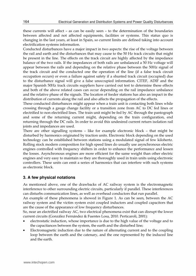
As mentioned above, one of the drawbacks of AC railway system is the electromagnetic interference to other surrounding electric circuits, particularly if parallel. These interferences can disturbs communication lines, as well as overhead conductors that run parallel. An example of these phenomena is showed in Figure 1. As can be seen, between the AC railway system and the victim system exist coupled inductors and coupled capacitors that are the cause of the appearance of low frequency disturbances. So, near an electrified railway AC, two electrical phenomena exist that can disrupt the lower current circuits (González Fernández & Fuentes Losa, 2010. Perticaroli, 2001):
• electrostatic induction, whose importance is due to the high value of the voltage and to the capacitances between the system, the earth and the disturbed line;
• Electromagnetic induction due to the nature of alternating current and to the coupling loop between the earth and the catenary, and the one represented by the induced line and the earth.
www.intechopen.com
Electrical Disturbances from High Speed Railway Environment to Existing Services
165
The resulting induced voltages in the victim system, in absence of protection, can cause hazards to personnel, material deterioration, problems in the proper functioning as unexpected operation of railway signaling installations.
Fig. 1. Coupled inductors and coupled capacitors between the disturbing line and the disturbed line
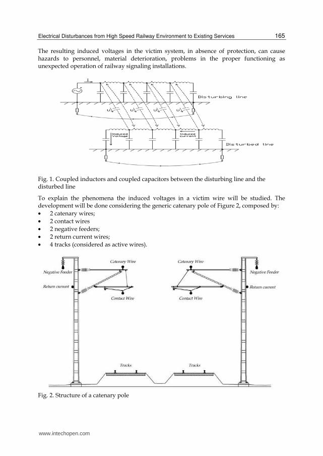
To explain the phenomena the induced voltages in a victim wire will be studied. The development will be done considering the generic catenary pole of Figure 2, composed by:
• 2 catenary wires;
• 2 contact wires
• 2 negative feeders;
• 2 return current wires;
• 4 tracks (considered as active wires).
Fig. 2. Structure of a catenary pole
www.intechopen.com
Electrical Generation and Distribution Systems and Power Quality Disturbances
166
3.1 Electrostatic induction The electric field consists of open field lines starting from the charge generating the field to other charges where field lines end. Considering a wire, the linear charge is calculated using the Gauss Law, stating that the electrical flux coming out of a closed surface is equal to the electrical charge contained in the surface (Arturi, 2008):
intQψ = (1)
Where the electrical flux in equal to the integral of the electrical flux density in a surface:
S
d D dS D dSρψΨ = = ⋅ = (2)
Considering a cylindrical conductor of radius ρ and length l the electrical flux is:
2D lρψ πρ= ⋅ (3)
The electrical charge is the integral of the linear charge in a line:
int l l
l
Q dl lλ λ= = ⋅ (4)
Where lλ is the linear charge density of the wire. Comparing the equation (3) and (4) the electrical flux is:
2 2 2
l lQ lD
l lρ
λ λ
πρ πρ πρ
⋅= = =
⋅ ⋅ (5)
And the electrical flux vector is:
2
lD D a aρ ρ ρ
λ
πρ= = (6)
The electrical field is proportional to the electrical flux vector through the permittivity of the material:
0D Eε= (7)
Where 120 8.85 10
F
mε −= ⋅ is the permittivity of vacuum.
Consequently the electrical field is:
0
DE
ε= (8)
0 0 02 2
lD l QE a a
l lρ ρ
λ
ε πρε πρε
⋅= = =
⋅ ⋅ (9)
Through the image theorem and considering the position of the catenary pole conductors, the electric field intensity inducted in a generic point (x,y) is due to the following relation expressing the influence of all the wires and its images to the point:
www.intechopen.com
Electrical Disturbances from High Speed Railway Environment to Existing Services
167
2 2
0
1( , )
2 ( ) ( )i
i i i
QE x y u
l x x y yπε= ⋅
− + − (10)
Where ix and iy are the coordinates of each wire. Using the electrical field is possible to calculate the potential induced on a wire through the definition of electrical potential:
'
r
r
V E dl= − ⋅ (11)
Where r is the generic point where the potential has to be calculated and r’ is the reference of the potential. From (9) and (11) we obtain:
0 0'
1ln
2 2 '
r
r
Q Q rV d
l l rρ
πε ρ πε= − ⋅ ⋅ = − ⋅ (12)
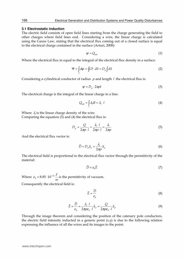
To calculate the influence of all the wires of the catenary pole the image theorem must be applied. In Figure 3 are showed the principal conductor and the respective image conductors in a standard High Speed Line catenary Pole. Wires 1-14 are the main wires and wires 1’-14’ are the images of the main wires. Wire 15 and 15’ are the victim wire and its image. a2,13 distance between wires 2-13. b2,8 distance between wires 2 to image of wire 8. h2 is the height of wire 2. The wire 15 is the hypothetical conductor exposed to the electrical field produced by all the catenary pole wires and by theirs images. The tracks are considered active wires.
Fig. 3. Application of the image method to High Speed Lines
www.intechopen.com
Electrical Generation and Distribution Systems and Power Quality Disturbances
168
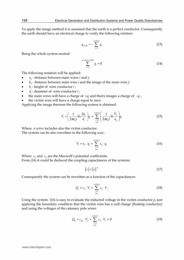
To apply the image method it is assumed that the earth is a perfect conductor. Consequently the earth should have an electrical charge to verify the following relation:
1
n wires
earth ii
q q=
= − (13)
Being the whole system neutral:
1
0n wires earth
ii
q+
=
= (14)
The following notation will be applied:
• ija : distance between main wires i and j;
• ijb : distance between main wire i and the image of the main wire j;
• ih : height of wire conductor i ;
• id : diameter of wire conductor i ;
• the main wires will have a charge of iq+ and theirs images a charge of iq− ;
• the victim wire will have a charge equal to zero. Applying the image theorem the following system is obtained:
10 0
1 2 1ln ln
2 2
n wiresiji
i i jji ijj i
bhV q q
l d l aπε πε=≠
= + (15)
Where n wires includes also the victim conductor. The system can be also rewritten in the following way:
1
n wires
i ii i ij jjj i
V s q s q=≠
= ⋅ + ⋅ (16)
Where iis and ijs are the Maxwell’s potential coefficients. From (16) it could be deduced the coupling capacitances of the systems:
[ ] [ ]1
c s−
= (17)
Consequently the system can be rewritten as a function of the capacitances:
1
n wires
i ii i ij jjj i
Q c V c V=≠
= ⋅ + ⋅ (18)
Using the system (16) is easy to evaluate the inducted voltage in the victim conductor p, just applying the boundary condition that the victim wire has a null charge (floating conductor) and using the voltages of the catenary pole wires:
1
0n wires
p pp p ij jjj i
Q c V c V=≠
= ⋅ + ⋅ = (19)
www.intechopen.com
Electrical Disturbances from High Speed Railway Environment to Existing Services
169
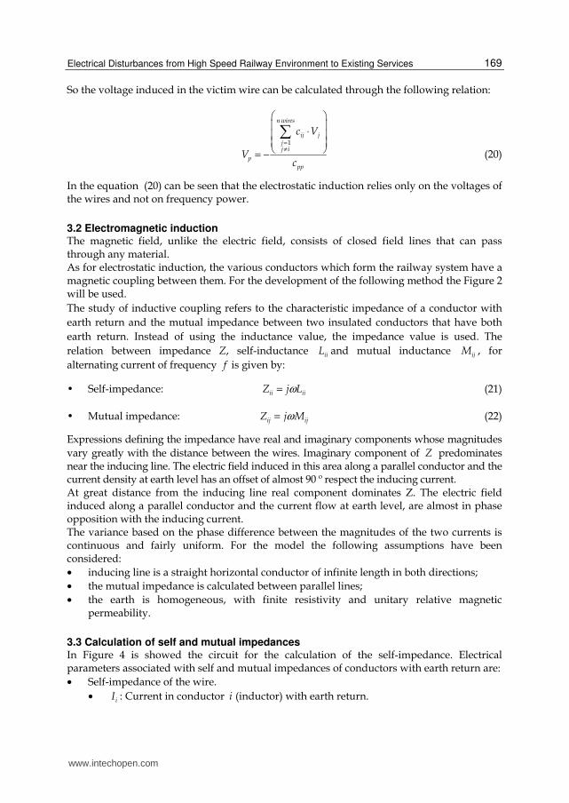
So the voltage induced in the victim wire can be calculated through the following relation:
1
n wires
ij jjj i
p
pp
c V
Vc
=≠
⋅ = −
(20)
In the equation (20) can be seen that the electrostatic induction relies only on the voltages of the wires and not on frequency power.
3.2 Electromagnetic induction The magnetic field, unlike the electric field, consists of closed field lines that can pass through any material. As for electrostatic induction, the various conductors which form the railway system have a magnetic coupling between them. For the development of the following method the Figure 2 will be used.
The study of inductive coupling refers to the characteristic impedance of a conductor with
earth return and the mutual impedance between two insulated conductors that have both
earth return. Instead of using the inductance value, the impedance value is used. The
relation between impedance Z, self-inductance iiL and mutual inductance ijM , for
alternating current of frequency f is given by:
Self-impedance: ii iiZ j Lω= (21)
Mutual impedance: ij ijZ j Mω= (22)
Expressions defining the impedance have real and imaginary components whose magnitudes
vary greatly with the distance between the wires. Imaginary component of Z predominates near the inducing line. The electric field induced in this area along a parallel conductor and the current density at earth level has an offset of almost 90 º respect the inducing current. At great distance from the inducing line real component dominates Z. The electric field induced along a parallel conductor and the current flow at earth level, are almost in phase opposition with the inducing current. The variance based on the phase difference between the magnitudes of the two currents is continuous and fairly uniform. For the model the following assumptions have been considered:
• inducing line is a straight horizontal conductor of infinite length in both directions;
• the mutual impedance is calculated between parallel lines;
• the earth is homogeneous, with finite resistivity and unitary relative magnetic permeability.
3.3 Calculation of self and mutual impedances In Figure 4 is showed the circuit for the calculation of the self-impedance. Electrical parameters associated with self and mutual impedances of conductors with earth return are:
• Self-impedance of the wire.
• iI : Current in conductor i (inductor) with earth return.
www.intechopen.com

Electrical Generation and Distribution Systems and Power Quality Disturbances
170
• 0iU : Voltage in the outer surface of conductor i caused by the current i.
• eiU : External voltage in the circuit formed by the conductor i and earth, caused by
the current i. The self-impedance can be defined as the sum of the following impedances:
0sii i eiZ Z Z= + (23)
Where the meaning of the terms is:
ssii
i
UZ
I l=
⋅ (24)
00
ii
i
UZ
I l=
⋅ (25)
eiei
i
UZ
I l=
⋅ (26)
Fig. 4. Calculation of the self-impedance
• Mutual impedance between two wires.
In Figure 5 is showed the circuit for the calculation of the mutual impedance. iI is the
current for the conductor I and ijU in the voltage in conductor j due to the current for the
current iI .
Fig. 5. Mutual impedance calculation
www.intechopen.com
Electrical Disturbances from High Speed Railway Environment to Existing Services
171
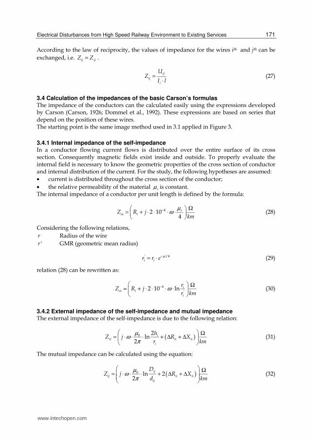
According to the law of reciprocity, the values of impedance for the wires ith and jth can be
exchanged, i.e. ij jiZ Z= .
ij
ij
i
UZ
I l=
⋅ (27)
3.4 Calculation of the impedances of the basic Carson’s formulas The impedance of the conductors can the calculated easily using the expressions developed by Carson (Carson, 1926; Dommel et al., 1992). These expressions are based on series that depend on the position of these wires. The starting point is the same image method used in 3.1 applied in Figure 3.
3.4.1 Internal impedance of the self-impedance In a conductor flowing current flows is distributed over the entire surface of its cross section. Consequently magnetic fields exist inside and outside. To properly evaluate the internal field is necessary to know the geometric properties of the cross section of conductor and internal distribution of the current. For the study, the following hypotheses are assumed:
• current is distributed throughout the cross section of the conductor;
• the relative permeability of the material rµ is constant. The internal impedance of a conductor per unit length is defined by the formula:
42 104
roi iZ R j
km
µω− Ω
= + ⋅ ⋅ ⋅ ⋅ (28)
Considering the following relations,
r Radius of the wire
'r GMR (geometric mean radius)
' /4i ir r e µ−= ⋅ (29)
relation (28) can be rewritten as:
4
'2 10 ln i
oi i
i
rZ R j
r kmω− Ω
= + ⋅ ⋅ ⋅ ⋅ (30)
3.4.2 External impedance of the self-impedance and mutual impedance The external impedance of the self-impedance is due to the following relation:
( )0 2ln
2i
ei ii ii
i
hZ j R X
r km
µω
π
Ω= ⋅ ⋅ ⋅ + Δ + Δ (31)
The mutual impedance can be calculated using the equation:
( )0 ln 22
ij
ij ii ii
ij
DZ j R X
d km
µω
π
Ω= ⋅ ⋅ ⋅ + Δ + Δ (32)
www.intechopen.com
Electrical Generation and Distribution Systems and Power Quality Disturbances
172
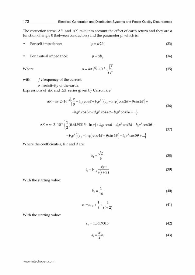
The correction terms RΔ and XΔ take into account the effect of earth return and they are a function of angle θ (between conductors) and the parameter p, which is:
For self-impedance: 2p hα= (33)
For mutual impedance: ijp bα= (34)
Where 44 5 10f
α πρ
−= ⋅ ⋅ (35)
with :f frequency of the current.
ρ : resistivity of the earth.
Expressions of RΔ and XΔ series given by Carson are:
( )
4 21 2 2
3 4 53 4 5
2 10 cos ln cos2 sin 28
cos3 cos 4 cos5 ...
R b p b p c p
b p d p b p
πω θ θ θ θ
θ θ θ
− Δ = ⋅ ⋅ − + − + + + − − +
(36)
( )
( )
4 2 31 2 3
4 54 4 5
12 10 0.6159315 ln cos cos2 cos3
2
ln cos 4 sin 4 cos5 ...
X p b p d p b p
b p c p b p
ω θ θ θ
θ θ θ θ
− Δ = ⋅ ⋅ − + − + −
− − + − + (37)
Where the coefficients a, b, c and d are:
1
2
6b = (38)
( )2
2i i
signb b
i i−=
+ (39)
With the starting value:
2
1
16b = (40)
2
1 1
( 2)i ic c
i i−= + +
+ (41)
With the starting value:
2 1.3659315c = (42)
4
i id bπ
= (43)
www.intechopen.com
Electrical Disturbances from High Speed Railway Environment to Existing Services
173
3.5 Voltage calculation
Once the matrix [ ]Z containing the self-impedances and the mutual impedances has been
calculated, the inducted voltage in the victim wire can be evaluated using the following
relation:
[ ] [ ] [ ]V Z IΔ = ⋅ (44)
1 1,1 1,13 1
13,1 14,13 1313
V Z Z I
Z Z IV
Δ = Δ
(45)
Voltage 13VΔ can be evaluated considering the border condition that 13 0i = :
12
13 13,1
i ii
V Z I=
Δ = ⋅ (46)
4. Field reduction
It is possible to prevent the problems caused by the electrostatic and electromagnetic coupling using some criteria that will be explained in next sections.
4.1 Electrostatic reduction As seen in section 3.1, the electric field produced by the conductors of the railway system induces a voltage in an eventual wire or in any conductive part not directly connected to the earth. Furthermore, the possible presence of electric field, due to atmospheric electrical charge present in that region of space, must be also the cause of the appearance of induced voltage in the victim conductor. For safety reasons any mass, in principle, is directly connected to the earth, to prevent a potential that can be dangerous for people, animals and things. Generally to allow the proper operation of the signaling systems the wires connecting the different elements are wires having a protective shield. This shield must be connected to earth in order to fix the potential to earth. If the shield is earthed, voltage Ushield = 0. For electrostatic reduction is enough to connect just an extreme of the shield to earth. In this case of connection, to guarantee the condition Ushield = 0, the shield must be earthed in more points along the line, as close as possible. In this way in the extreme not connected to earth, the voltage to earth will be low and it can be assumed Ushield ≈ 0. If the section is too long there will be fewer guarantees to maintain Uscreen = 0. Considering equation (15), (16) and (17) it can be seen that capacitances depend on the length of the shielding: decreasing the length decreases the capacitance, and consequently the electrostatic effect is reduced. The shield could also be earthed in both ends. In this case it is very important to earth the shield along the line often, to reduce the magnetic coupling. Closing the shield it forms a spire and consequently it can be victim of electromagnetic coupling.
4.2 Electromagnetic reduction Protection against electromagnetic induction is hard to achieve. As explained in section 3.2, the magnetic coupling between the railway system and the victim conductor produces
www.intechopen.com
Electrical Generation and Distribution Systems and Power Quality Disturbances
174
induced voltages depending on the position of the different conductors. In the case of high-speed lines, the inducing circuit is composed by the loop power substation-overhead wire-train-rails. The current that is circulating varies in time with a given frequency and produces a magnetic field of the same frequency. This magnetic field induces an electromotive force in the circuit composed by the victim conductor and the earth, and consequently an induced current in the victim circuit will be generated. To protect the signaling system from voltages induced by electromagnetic coupling in general in railways are used cables with a factor reduction. Besides of the electrostatic shields, these kinds of cables have another shield against the electromagnetic effects. Using these kind of shields it is possible to reduce the magnetic field and consequently to reduce the induced voltages and currents. The reduction factor or factor shielding as the mitigation of electromagnetic fields produced by a power line by the presence of shields or other metal objects:
1
2
VK
V= (47)
Where 1V is the voltage induced in presence of these shields and 2V is the voltage that
would be induced in their absence. Thus the reduction factor will always be less than the
unit. In general there are 2 families of magnetic screen:
• Magnetic screen with magnetic material;
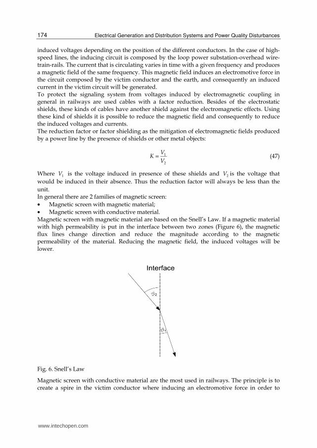
• Magnetic screen with conductive material. Magnetic screen with magnetic material are based on the Snell’s Law. If a magnetic material with high permeability is put in the interface between two zones (Figure 6), the magnetic flux lines change direction and reduce the magnitude according to the magnetic permeability of the material. Reducing the magnetic field, the induced voltages will be lower.
Fig. 6. Snell’s Law
Magnetic screen with conductive material are the most used in railways. The principle is to create a spire in the victim conductor where inducing an electromotive force in order to
www.intechopen.com
Electrical Disturbances from High Speed Railway Environment to Existing Services
175
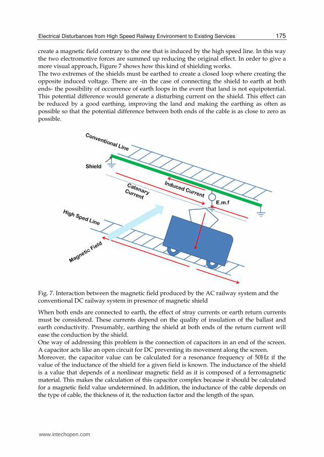
create a magnetic field contrary to the one that is induced by the high speed line. In this way the two electromotive forces are summed up reducing the original effect. In order to give a more visual approach, Figure 7 shows how this kind of shielding works. The two extremes of the shields must be earthed to create a closed loop where creating the opposite induced voltage. There are -in the case of connecting the shield to earth at both ends- the possibility of occurrence of earth loops in the event that land is not equipotential. This potential difference would generate a disturbing current on the shield. This effect can be reduced by a good earthing, improving the land and making the earthing as often as possible so that the potential difference between both ends of the cable is as close to zero as possible.
Fig. 7. Interaction between the magnetic field produced by the AC railway system and the conventional DC railway system in presence of magnetic shield
When both ends are connected to earth, the effect of stray currents or earth return currents must be considered. These currents depend on the quality of insulation of the ballast and earth conductivity. Presumably, earthing the shield at both ends of the return current will ease the conduction by the shield. One way of addressing this problem is the connection of capacitors in an end of the screen. A capacitor acts like an open circuit for DC preventing its movement along the screen. Moreover, the capacitor value can be calculated for a resonance frequency of 50Hz if the value of the inductance of the shield for a given field is known. The inductance of the shield is a value that depends of a nonlinear magnetic field as it is composed of a ferromagnetic material. This makes the calculation of this capacitor complex because it should be calculated for a magnetic field value undetermined. In addition, the inductance of the cable depends on the type of cable, the thickness of it, the reduction factor and the length of the span.
www.intechopen.com
Electrical Generation and Distribution Systems and Power Quality Disturbances
176
5. How to protect systems and equipment from electrical disturbations
Once that the problems have been described and the physical phenomena were formulated in the above sections this section will describe how electrical disturbances in already existing railway lines can be lessen or eliminated. In the next subsections a compendium of solutions is exposed.
5.1 Track circuits Track circuits, as has been shown in this chapter, are safety elements that can be affected by disturbances. Since it has been demonstrated that this kind of devices can be altered by disturbances, the recommendation is to change them for audiofrequency track circuits in order to avoid malfunctioning. In order to determine which track circuits should be replaced simulations are performed in order to determine the induced voltage level between both rails. When this simulated voltage level is above a determined disturbance level, a decision to change them is carried out. The induced level of voltage is function of the current circulating through the overhead wire system in the high speed line, the distance between both lines, the angle between them, the distance between the rails (UIC gauge, Spanish gauge…), and the length of the track circuit section. When direct contact disturbances might occur, usually nearby a gauge changing facility or a electrification changing section isolation rail joints might be used. In order to avoid that train units could shortcut both electrical zones two isolation joints can be placed with a separation bigger than the length of the largest train that will pass by that lines. When isolation joints cannot be deployed due to traction return problems, impedances can be used. In the Spanish example impedances are installed in order to offer a high impedance at 50 Hz and low impedance at zero frequency. This ‘high impedance’ circuit for 50 Hz and higher frequency is built as a low pass filter to offer maximum impedance at 50 Hz. Thus the 50 Hz current that would flow through the DC rails is dramatically reduced. According to the measures made in some gauge changing facilities the reduction of the flowing current through conventional rails can be reduced from 1/4 to 1/2 of the current that would be present if no impedance was present. These impedances are useless in transitions between electrified and non electrified lines since only isolation joints are needed to avoid the presence of 50 Hz current through the rails. The electrified rail cannot have isolation joints in order to allow the traction current to return to the feeder station. Since these impedances have a direct effect in the safety of the line they should be monitored in order to detect malfunctions. If they are not monitored, no assumption can be made regarding the reduction of the section of the line where 50 Hz track circuits should be replaced by audiofrequency ones. The way to calculate the boundary between affected and not affected zones is to determine the distance where there’s a current through the rails equivalent to that of the normal operation of the track circuits. This distance can be as long as 18 km depending on the technology.
5.2 Signalling and communications wires Wires are used in railway signalling in order to connect the interlocking with the field elements. These wires are spread in parallel along the track and some of them can have a length of several kilometres. The input signals to the interlocking are basically the state of the track circuits (occupied/unoccupied), the position of the points and the current state of the light signals, and the outputs are the orders to the points and the orders to the signals.
www.intechopen.com
Electrical Disturbances from High Speed Railway Environment to Existing Services
177
These orders are usually 50 Hz signals. They can be of a different range of voltages that can vary between 50 to 220 volts. So there is a chance that induced voltages can either turn off one aspect of the signal, which would only affect operation of the line, or can turn it on what can affect safety. Communication wires are laid along the line from one station to their collaterals. Voice services are transmitted via these wires and also data. 50 Hz disturbances in these wires can affect communications, but are not likely to have an influence in safety issues. Block wires connect collateral stations. This is a coded signal that is not likely to be affected by 50 Hz disturbances, but can be affected by harmonic disturbances caused by the rolling stock. In order to protect these services from disturbances several actions can be carried out:
• Wires can be substituted by fiber optic that is immune to electrical disturbances. This is a good solution, especially for communications and services between stations.
• Wires can be shielded. This shield has to be earthed on both ends in order to provide effective shielding against both inductive coupling and capacitive coupling. This way of shielding is very effective against disturbances, but gives a good return for DC circulating through earth back to the feeder station.
• Wires can be shielded with both ends earthed, but in one side earthing is made through a capacitor (Koopal & Evertz, 2008). Thus no DC would return using the shield. This is an expensive way because each capacitor has to be calculated depending on the length of wire and the resistivity of the earth in order to obtain a minimum impedance at 50 Hz frequency so shielding against 50 Hz electrical disturbances is effective.
5.3 Level crossings Railway level crossings are particular signalling systems that can be or not be connected to
other signalling systems such as interlocking. These systems are in charge of protecting cars
and citizens from railways. Level crossings electronic systems can be triggered by the
interlocking or by track pedal that gives a train announcement to the system. These facilities
have also wires that can have a length of more than two kilometres. The solutions to immunize these systems from disturbances are the same one that those stated above for signalling and communication wires.
5.4 Accessible metallic elements According to EN 50122-1 we can define the following terms:
• Rail potential (EN 50122-1): The voltage occurring under operating conditions when the running rails are utilised for carrying the traction return current or under fault conditions between running rails and earth.
• Accessible voltage (EN 50122-1):That part of the rail potential under operating conditions which can be bridged by persons, the conductive path being conventionally from hand to both feet through the body or from hand to hand.
• Touch voltage (EN 50122-1): Voltage under fault conditions between parts when touched simultaneously.
As was described above, usually DC rails used in traction lines are isolated from earth in
order to prevent stray currents. This measure can raise rail potential. This can happen even
without tractor trains in the line if there’s a parallel high speed line nearby. Passenger might
want to cross from one platform to other crossing the rails even if it’s forbidden. This is
more common in small stations with low traffic density.
www.intechopen.com

Electrical Generation and Distribution Systems and Power Quality Disturbances
178
There are other elements that have similar problems like the wire fences used to prevent intrusions in high speed lines. Also metal structures in big stations like metallic shelters that are not adequately earthed can have accessible voltages that have to be measured in order to check that there are not over the limits established by the standards. In order to keep the accessible voltage or the touch voltage below the established limits, and as is reflected in the standard EN 50122-1, voltage limiting devices (VLD) can be connected between earth and rail, fence or structure. These devices keep both parts isolated from each other until the voltage between them exceeds a certain defined value, then it connects both parts so there is an electrical circulation between both systems and after that the VDL opens the circuit and checks the voltage between both parts. Another solution that cannot be used for rails is to have a good earthing circuit. Metallic shelters or metallic fences should be adequately connected to earth in order to prevent accidents or electrocutions.
6. Measurements methodology
CITEF has performed several measurements campaigns in order to determine whether the systems and facilities used in conventional lines described above are well protected against disturbances or not. A measurement methodology was used and will be presented here. This methodology has been enhanced with the experience acquired and the analysis of the results. Measurements were carried out in the following elements:
• 50 Hz track circuits placed in the boundary section between 50 Hz track circuits unmodified and audiofrequency track circuits.
• Communication wires between stations. They are measured at each end of the electrical pairs or quads and loaded with the characteristic impedance of the line.
• Signal aspects. In this position, a lit aspect and a switched off aspect are measured in order to determine whether or not are affected by disturbances.
• Touch voltage in the metallic elements like fences, signal posts, point engines, lampposts, etc. surrounding the measurement position and of the rails according to EN 50122-1 Annex E: Measurement methods for touch voltage.
In order to obtain good accurate results a pole is disposed in a determined position of the high speed line to shortcut the electrical overhead wire system and the rail. Calculations are made in order to determine that point considering the position of the feeder stations, the impedance of the rail and the impedance of the overhead wires. 1x25 kV scheme is adopted even if electric trackside facilities are 2x25 kV. This is made so because this electrification scheme is more disturbing and return impedance is higher. This is done this way in order to obtain a steady state current as close as possible as 1200 A. This current is determined by the estimated amount of energy needed when two double train compositions accelerate at full throttle simultaneously in the same electrical section. This is an ADIF (Spanish Railway Infrastructure Manager) requirement. Sometimes because of the topology of the line, the situation of the feeder stations and the electric network, that current level cannot be obtained. In that case, lower currents are considered and measured. In order to determine the position of the short-circuit pole, calculations are performed using a CITEF self developed application that implements these electrical calculations, but this calculations can be estimated easily knowing the impedance of the elements (rail and overhead contact line), the voltage level in the feeder station and the position of the feeder stations in the line.
www.intechopen.com
Electrical Disturbances from High Speed Railway Environment to Existing Services
179
The use of this shortcut steady state current is of great value in order to assure the
repetitiveness of the measures. A real traction unit won’t allow a steady state current to be
maintained in order to measure the effects in the determined elements.
To measure touch voltage the EN 50122-1 Annex E methodology is used. The methodology
described in the standard can be summarized in the following aspects:
• The voltage shall be measured with a voltimeter that has an internal resistance of 1 kΩ.
• Each measuring electrode, in order to simulate one feet, shall have a total area of 400
cm2 and shall be pressed on the earth with a minimum force of 500 N. Alternatively, a
sensor driven 20 cm into the earth may be used instead of the measuring electrode.
• To measure the touch voltages/accessible voltage in concrete surfaces or dry up soils, a
wet cloth or a water film shall be placed between the foot electrodes and the earth. The
foot electrodes shall be positioned at a distance not less than 1 meter from the accessible
conductive part.
• A measuring electrode, usually a tip electrode, shall be used in order to simulate a
hand. In this case paint coatings (but not insulations) shall be pierced.
• One clamp of the voltimeter shall be connected to the so called hand electrode and the
other clamp shall be connected to the so called foot electrode.
• It is enough to carry out such measurements by random checks of an installation.
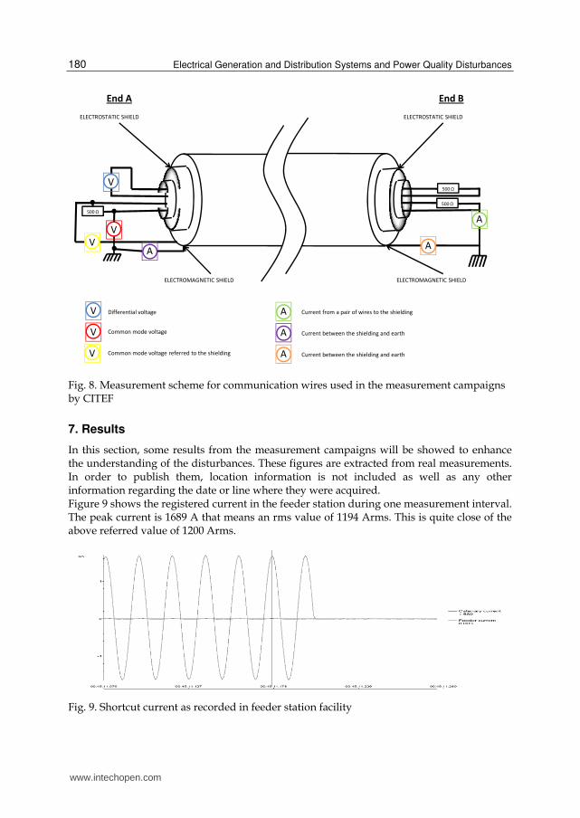
In Figure 8 it is shown the connection scheme to measure the communication wires.
In order to perform the measures a quad is used. This quad is loaded in the determined
ends with the characteristic impedance of the wire that is usually a value between 500 to 600
Ω depending on the wire. These measures are carried out with the shielding of both ended
connected and with one of the ends unconnected in order to determine the disturbance
induced when the shielding in not properly connected.
These measures are usually done by two measurement teams each one of them placed at
each one of the ends usually in a station communication facility. In order to comply with the
measurement procedure a continuity of the shielding from one end to the other of the wire
needs to be achieved. This was not always possible because DC stray currents could be a
more important problem than preventing AC disturbances. In these cases, only prevention
against electrostatic field was achieved since only one end of the shield was correctly
earthed while the other end was unconnected.
The differentiation between electromagnetic shield and electrostatic shield needs to be
clarified. In order to prevent electromagnetic disturbances both shields must be connected
between them and connected to earth according to the standard ITU K14 Provision of a
metallic screen in plastic-sheathed cables. The electrostatic shield is just a copper
conductor. It is enough to earth just one end of the shield to prevent electrostatic
disturbances.
When measures were carried out in a 50 Hz track circuit the measured values were:
• The track voltage in the receiver.
• The transformed track voltage (if transformers were used) in the relay.
• The state of the track circuit (occupied/unoccupied)
These measures should be carried out shunting the emitter and without shunting it in order
to determine the disturbance in both situations. As said before, one of them –occupancy of
an unoccupied track circuit- has operational implications and the other one –liberation of an
occupied track circuit- has safety implications.
www.intechopen.com
Electrical Generation and Distribution Systems and Power Quality Disturbances
180
V
ELECTROSTATIC SHIELD
ELECTROMAGNETIC SHIELD
ELECTROSTATIC SHIELD
ELECTROMAGNETIC SHIELD
500 Ω
V
V
500 Ω
500 Ω
A
AA
V
V
V
A
A
A
Differential voltage
Common mode voltage
Common mode voltage referred to the shielding
Current from a pair of wires to the shielding
Current between the shielding and earth
Current between the shielding and earth
End BEnd A
Fig. 8. Measurement scheme for communication wires used in the measurement campaigns by CITEF
7. Results
In this section, some results from the measurement campaigns will be showed to enhance the understanding of the disturbances. These figures are extracted from real measurements. In order to publish them, location information is not included as well as any other information regarding the date or line where they were acquired. Figure 9 shows the registered current in the feeder station during one measurement interval. The peak current is 1689 A that means an rms value of 1194 Arms. This is quite close of the above referred value of 1200 Arms.
Fig. 9. Shortcut current as recorded in feeder station facility
www.intechopen.com
Electrical Disturbances from High Speed Railway Environment to Existing Services
181
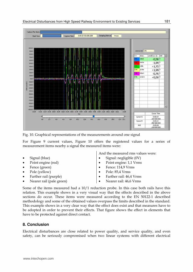
Fig. 10. Graphical representations of the measurements around one signal
For Figure 9 current values, Figure 10 offers the registered values for a series of measurement items nearby a signal the measured items were:
• Signal (blue)
• Point engine (red)
• Fence (green)
• Pole (yellow)
• Farther rail (purple)
• Nearer rail (pale green)
And the measured rms values were:
• Signal: negligible (0V)
• Point engine: 1,1 Vrms
• Fence: 114,9 Vrms
• Pole: 85,4 Vrms
• Farther rail: 46,4 Vrms
• Nearer rail: 46,6 Vrms
Some of the items measured had a 10/1 reduction probe. In this case both rails have this relation. This example shows in a very visual way that the effects described in the above sections do occur. These items were measured according to the EN 50122-1 described methodology and some of the obtained values overpass the limits described in the standard. This example shows in a very clear way that the effect does exist and that measures have to be adopted in order to prevent their effects. That figure shows the effect in elements that have to be protected against direct contact.
8. Conclusion
Electrical disturbances are close related to power quality, and service quality, and even safety, can be seriously compromised when two linear systems with different electrical
www.intechopen.com
Electrical Generation and Distribution Systems and Power Quality Disturbances
182
feeder schemes are deployed one next to other and have even direct electrical contact between them. Electrical systems in DC and AC railway systems are designed separately, especially considering earthing, and this leads to new problems that weren’t faced when old DC lines were design, deployed and operated. Disturbances are a common issue that an engineer has to face while designing a new facility or system. Disturbances can also appear when the system is already in operation. These systems need to be protected from the effects of the disturbances in the most effective ways. These ways are usually the replacement of equipments (or at least part of them) and the shielding against those electrical disturbances. In the above sections it has been explained the effects that disturbances from high speed lines can cause on conventional DC lines. A measurement methodology has been proposed. This methodology was used in on site measuring campaigns and their results have been used as a validation of the protecting works carried out before the high speed line comes into operation. The determination of the boundaries between what needs to be changed and what does not need to be changed is a complex problem that must be solved in a cost effective way, but without reducing safety issues. The different ways of disturbance have been presented and explained so a global vision of the problem can be easily achieved.
9. References
Arturi, C. M. (2008). Campi elettrici, magnetici e di conduzione – introduzione ai metodi computazionali, Maggioli Editore, ISBN: 978-88387-4248-4. Milano, Italy.
Carson, J. R. (1926). Wave propagation in overhead wires with earth return, Bell systems technical journal, Vol. 5, No. 4, (Oct. 1926), pp 539 – 554.
Dommel, H. W. et al (1992). Electro – Magnetic Transient Program (EMTP). Theory Book. González Fernández, F. J. & Fuentes Losa. (2010) (2nd edition). J. Ingeniería Ferroviaria (2nd
edition), UNED Editorial, ISBN: 978-84-362-6074-8. Madrid, Spain. Koopal, R. & Evertz, E. P. (2008). 50 Hz Track Circuits Parallel to a 25 kV 50 Hz Railway
Line, proceedings of World Congress on Railway Research, ISBN, Seoul, May 2008. Perticaroli, F. (2001). Sistemi elettrici per i transporti. Trazione Elettrica (2nd edition), Casa
Editrice Ambrosiana, ISBN: 88-408-1035-8. Milano, Italy.
www.intechopen.com
Electrical Generation and Distribution Systems and Power QualityDisturbancesEdited by Prof. Gregorio Romero
ISBN 978-953-307-329-3Hard cover, 304 pagesPublisher InTechPublished online 21, November, 2011Published in print edition November, 2011
InTech EuropeUniversity Campus STeP Ri Slavka Krautzeka 83/A 51000 Rijeka, Croatia Phone: +385 (51) 770 447 Fax: +385 (51) 686 166www.intechopen.com
InTech ChinaUnit 405, Office Block, Hotel Equatorial Shanghai No.65, Yan An Road (West), Shanghai, 200040, China
Phone: +86-21-62489820 Fax: +86-21-62489821
The utilization of renewable energy sources such as wind energy, or solar energy, among others, is currentlyof greater interest. Nevertheless, since their availability is arbitrary and unstable this can lead to frequencyvariation, to grid instability and to a total or partial loss of load power supply, being not appropriate sources tobe directly connected to the main utility grid. Additionally, the presence of a static converter as output interfaceof the generating plants introduces voltage and current harmonics into the electrical system that negativelyaffect system power quality. By integrating distributed power generation systems closed to the loads in theelectric grid, we can eliminate the need to transfer energy over long distances through the electric grid. In thisbook the reader will be introduced to different power generation and distribution systems with an analysis ofsome types of existing disturbances and a study of different industrial applications such as battery charges.
How to referenceIn order to correctly reference this scholarly work, feel free to copy and paste the following:
Juan de Dios Sanz-Bobi, Jorge Garzo n-Nu n ez, Roberto Loiero and Jesu s Fe lez (2011). ElectricalDisturbances from High Speed Railway Environment to Existing Services, Electrical Generation andDistribution Systems and Power Quality Disturbances, Prof. Gregorio Romero (Ed.), ISBN: 978-953-307-329-3,InTech, Available from: http://www.intechopen.com/books/electrical-generation-and-distribution-systems-and-power-quality-disturbances/electrical-disturbances-from-high-speed-railway-environment-to-existing-services

© 2011 The Author(s). Licensee IntechOpen. This is an open access articledistributed under the terms of the Creative Commons Attribution 3.0License, which permits unrestricted use, distribution, and reproduction inany medium, provided the original work is properly cited.