Embed Size (px)
Citation preview
Product group index
Tubular cable lugs and connectors blue connection® - Cu 24
Tubular cable lugs 26
Butt connectors 28
Tool application chart 29
Copper tubular cable lugs and connectors - Cu 30
Tubular cable lugs 32
Angle tubular cable lugs 36
Connectors 40
Insulated tubular cable lugs and connectors 44
Tubular cable lugs and connectors for fi ne stranded conductors 47
Tubular cable lugs and compression joints for solid conductors 51
Tubular cable lugs for switchgear connections 54
Tool application chart 55
Tubular cable lugs and connectors - nickel, stainless steel 62
Stainless steel tubular cable lugs and connectors 64
Tubular cable lugs and connectors - nickel 66
Tool application chart 68
Copper compression cable lugs and connectors to DIN 70
Compression cable lugs acc. to DIN 46235 72
Angle compression cable lugs 74
Compression cable lugs, special type 77
Compression joints acc. to DIN 46267, part 1 and similar versions 79
Tool application chart 84
Terminals, connectors and pin terminals to DIN - Cu 86
Solderless terminals acc. to DIN 46234 88
Insulated solderless terminals 90
Solderless terminals, fork and pin type 92
Insulated solderless terminals for meter connections 94
Solderless connectors acc. to DIN 46341 95
Tool application chart 97
Sleeves for compacted conductors and sector-shaped conductors - Cu 100
Aluminum compression cable lugs and connectors to DIN 106
Compression cable lugs acc. to DIN 46329 and similar versions - Al 108
Compression joints acc. to DIN 46267, part 2 and similar versions - Al 110
Reduction compression joints – Al 112
Compression joints, full tension – Al 115
Compression cable lugs and connectors for AI/St cables DIN EN 50182 - Al 116
Tool application chart 118
Aluminum/copper compression cable lugs and connectors 122
Compression cable lugs - AI/Cu 124
Compression joints - Al/Cu 126
Bi-metallic washer 129
Tool application chart 130
Electrical connection systems
22
Klauke Hauptkatalog EN_DIN A5.indb 22 07.10.2014 12:16:03
Product group index
Torsten Selbach,Technical Support
Build on our experience:
No matter what the application,
we guarantee safe electrical connections.“
Clamps and screw connectors 132
Punched cable lugs - Cu 134
Screw connectors with soldering hole - CuZn 135
Parallel groove clamps for tap off connections - Cu 137
C and H-shaped clamps - Cu 139
Screw connectors for street lighting - CuZn 141
Screw connectors, high resistant aluminum alloy 142
Compact tap connectors, high resistant aluminum alloy 147
Tool application chart 150
Cable end-sleeves 152
Cable end-sleeves acc. to DIN 46228, part 1 and part 2 154
Insulated cable end-sleeves acc. to DIN 46228, part 4 and similar versions 157
Insulated cable end-sleeves for short circuit resistant conductors 162
Insulated twin cable end-sleeves 162
Insulated cable end-sleeves, strips and tapes 163
Tool application chart 165
Cable connections, insulated and non insulated 172
Insulated terminals 174
Non-insulated receptacles 184
Flexible connectors 188
Tool application chart 193
Assortments 196
Assortment boxes with tubular und compression cable lugs 198
Pocket boxes with cable end-sleeves 200
Pocket boxes with insulated cable end-sleeves 201
Assortment boxes with cable end-sleeves 206
Assortment boxes with insulated cable end-sleeves 206
Assortment boxes with insulated terminals 209
Electrical connection systems
23
Klauke Hauptkatalog EN_DIN A5.indb 23 07.10.2014 12:16:06
blue connection® – because modern cables have
narrower diameters
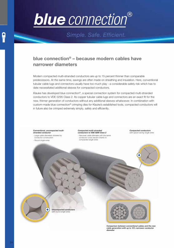
Modern compacted multi-stranded conductors are up to 15 percent thinner than comparable
predecessors. At the same time, savings are often made on sheathing and insulation. Here, conventional
tubular cable lugs and connectors usually have too much play - a considerable safety risk which has to
date necessitated additional sleeves for compacted conductors.
Klauke has developed blue connection®, a special connection system for compacted multi-stranded
conductors to VDE 0295 Class 2. Its copper tubular cable lugs and connectors are an exact fi t for the
new, thinner generation of conductors without any additional sleeves whatsoever. In combination with
custom-made blue connection® crimping dies for Klauke’s established tools, compacted conductors will
in future also be crimped extremely simply, safely and effi ciently.
Compacted conductors with space-saving single wires
Comparison between conventional cables and the new cable generation with up to 15% narrower conductor diameter
Uncompacted conductors with round single wires
Conventional, uncompacted multi-stranded conductor - Large cable diameters dictated by
conductor construction
- Round single wires
Compacted multi-stranded conductors to VDE 0295 Class 2- Narrower cable diameter with the same
conductor cross-section thanks to compacted single wires
Simple. Safe. Efficient.
24
Klauke Hauptkatalog EN_DIN A5.indb 24 07.10.2014 12:16:08

■ New designation – Safely connected.
▸ Designated by manufacturer’s designation,
nominal cross-section and hole dimension.
▸ Crimping direction and number of crimps.
▸ Compact design with form radius.
▸ Tested to IEC 61238, part 1.
Benefi ts:
▸ All information available at a glance.
▸ Bad crimps are avoided.
▸ Highly-stable and vibration-proof.
■ Effi cient: High productivity, low costs ▸ New crimp geometries reduce the number of crimps.
▸ The processing of sleeves for compacted conductors is eliminated.
▸ Up to 35% less material used thanks to the compact design.
▸ Smaller packing units.
Benefi ts:
▸ Less time and lower cost expenditure when using the new cable lug
system.
▸ Processing of sleeves for compacted conductors is eliminated.
▸ Lower material costs.
▸ Reducing storage costs through reduced material usage.
Only blue fits exactly!Only blue fits exactly!
Cable lug Crimping die Tool
osts
minated.
gn.
cable lug
ated.
■ Simply assign and crimp.
▸ Perfect fi t on compacted conductors to VDE 0295
Class 2.
▸ Simple assignment of crimping tool/crimping die
through colour-coding system.
▸ Existing tools with replaceable crimping dies can
continue to be used with blue connection® products.
Benefi ts:
▸ Crimping of compacted conductors without additional
sleeves.
▸ No investment in new tools, only the crimping dies are
replaced.
Characteristic form radius ensures stability and space for washers
New designation system
400 = nominal cross-sectionb = blue connection®
16 = connecting bolt Ør = conductor class (UL-compliant)
Manufacturer’s designationguarantees original Klauke product quality
New blue crimp info shows the number of crimps and crimping direction
Optional inspection hole in the cable lug for checking the conductor’s position
Cable lug with blue crimp info + blue crimping die + blue crimping tool = blue connection®
Simple. Safe. Efficient.
25
Klauke Hauptkatalog EN_DIN A5.indb 25 07.10.2014 12:16:09
6B5grp
Electrical connection systemsElectrical connection systems
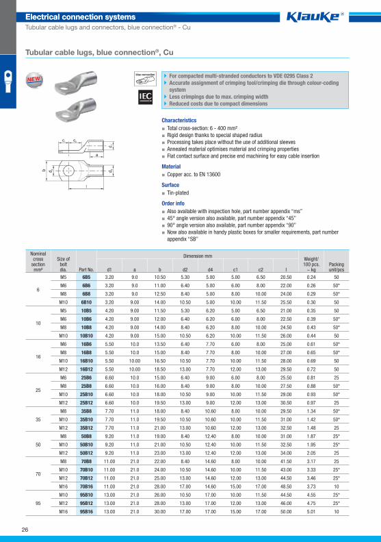
Tubular cable lugs and connectors, blue connection® - Cu
Tubular cable lugs, blue connection®, Cu
blue connection For compacted multi-stranded conductors to VDE 0295 Class 2
Accurate assignment of crimping tool/crimping die through colour-coding
system
Less crimpings due to max. crimping width
Reduced costs due to compact dimensions
Characteristics
▪ Total cross-section: 6 - 400 mm²
▪ Rigid design thanks to special shaped radius
▪ Processing takes place without the use of additional sleeves
▪ Annealed material optimises material and crimping properties
▪ Flat contact surface and precise end machining for easy cable insertion
Material
▪ Copper acc. to EN 13600
Surface
▪ Tin-plated
Order info
▪ Also available with inspection hole, part number appendix “ms”
▪ 45° angle version also available, part number appendix “45”
▪ 90° angle version also available, part number appendix “90”
▪ Now also available in handy plastic boxes for smaller requirements, part number
appendix “SB”
Nominal cross
section mm²
Size ofboltdia.
Dimension mm Weight/100 pcs.
~ kg Packing unit/pcs Part No. d1 a b d2 d4 c1 c2 l
6
M5 6B5 3.20 9.0 10.50 5.30 5.00 5.00 6.50 20.50 0.24 50
M6 6B6 3.20 9.0 11.00 6.40 5.00 6.00 8.00 22.00 0.26 50*
M8 6B8 3.20 9.0 12.50 8.40 5.00 8.00 10.00 24.00 0.29 50*
M10 6B10 3.20 9.00 14.00 10.50 5.00 10.00 11.50 25.50 0.30 50
10
M5 10B5 4.20 9.00 11.50 5.30 6.20 5.00 6.50 21.00 0.35 50
M6 10B6 4.20 9.00 12.00 6.40 6.20 6.00 8.00 22.50 0.39 50*
M8 10B8 4.20 9.00 14.00 8.40 6.20 8.00 10.00 24.50 0.43 50*
M10 10B10 4.20 9.00 15.00 10.50 6.20 10.00 11.50 26.00 0.44 50
16
M6 16B6 5.50 10.0 13.50 6.40 7.70 6.00 8.00 25.00 0.61 50*
M8 16B8 5.50 10.0 15.00 8.40 7.70 8.00 10.00 27.00 0.65 50*
M10 16B10 5.50 10.00 16.50 10.50 7.70 10.00 11.50 28.00 0.69 50
M12 16B12 5.50 10.00 18.50 13.00 7.70 12.00 13.00 29.50 0.72 50
25
M6 25B6 6.60 10.0 15.00 6.40 9.00 6.00 8.00 25.50 0.81 25
M8 25B8 6.60 10.0 16.00 8.40 9.00 8.00 10.00 27.50 0.88 50*
M10 25B10 6.60 10.0 18.00 10.50 9.00 10.00 11.50 29.00 0.93 50*
M12 25B12 6.60 10.0 19.50 13.00 9.00 12.00 13.00 30.50 0.97 25
35
M8 35B8 7.70 11.0 18.00 8.40 10.60 8.00 10.00 29.50 1.34 50*
M10 35B10 7.70 11.0 19.50 10.50 10.60 10.00 11.50 31.00 1.42 50*
M12 35B12 7.70 11.0 21.00 13.00 10.60 12.00 13.00 32.50 1.48 25
50
M8 50B8 9.20 11.0 19.00 8.40 12.40 8.00 10.00 31.00 1.87 25*
M10 50B10 9.20 11.0 21.00 10.50 12.40 10.00 11.50 32.50 1.95 25*
M12 50B12 9.20 11.0 23.00 13.00 12.40 12.00 13.00 34.00 2.05 25
70
M8 70B8 11.00 21.0 22.00 8.40 14.60 8.00 10.00 41.50 3.17 25
M10 70B10 11.00 21.0 24.00 10.50 14.60 10.00 11.50 43.00 3.33 25*
M12 70B12 11.00 21.0 25.00 13.00 14.60 12.00 13.00 44.50 3.46 25*
M16 70B16 11.00 21.0 28.00 17.00 14.60 15.00 17.00 48.50 3.73 10
95
M10 95B10 13.00 21.0 26.00 10.50 17.00 10.00 11.50 44.50 4.55 25*
M12 95B12 13.00 21.0 28.00 13.00 17.00 12.00 13.00 46.00 4.75 25*
M16 95B16 13.00 21.0 30.00 17.00 17.00 15.00 17.00 50.00 5.01 10
WW
26
Klauke_Hauptkatalog_ElektrVerbindungstechnik_01_RohrkabelschuhUndVerbinder-CU_GB.indd 26 10.10.2014 11:56:15
Electrical connection systemsElectrical connection systems
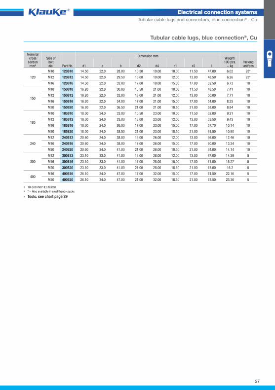
Tubular cable lugs and connectors, blue connection® - Cu
Tubular cable lugs, blue connection®, Cu
Nominal cross
section mm²
Size ofboltdia.
Dimension mm Weight/100 pcs.
~ kg Packing unit/pcs Part No. d1 a b d2 d4 c1 c2 l
120
M10 120B10 14.50 22.0 28.00 10.50 19.00 10.00 11.50 47.00 6.02 25*
M12 120B12 14.50 22.0 29.50 13.00 19.00 12.00 13.00 48.50 6.26 25*
M16 120B16 14.50 22.0 32.00 17.00 19.00 15.00 17.00 52.50 6.73 10
150
M10 150B10 16.20 22.0 30.00 10.50 21.00 10.00 11.50 48.50 7.41 10
M12 150B12 16.20 22.0 32.00 13.00 21.00 12.00 13.00 50.00 7.71 10
M16 150B16 16.20 22.0 34.00 17.00 21.00 15.00 17.00 54.00 8.25 10
M20 150B20 16.20 22.0 36.50 21.00 21.00 18.50 21.00 58.00 8.84 10
185
M10 185B10 18.00 24.0 33.00 10.50 23.00 10.00 11.50 52.00 9.21 10
M12 185B12 18.00 24.0 33.00 13.00 23.00 12.00 13.00 53.50 9.43 10
M16 185B16 18.00 24.0 36.00 17.00 23.00 15.00 17.00 57.70 10.14 10
M20 185B20 18.00 24.0 38.50 21.00 23.00 18.50 21.00 61.50 10.90 10
240
M12 240B12 20.60 24.0 38.00 13.00 26.00 12.00 13.00 56.00 12.46 10
M16 240B16 20.60 24.0 38.00 17.00 26.00 15.00 17.00 60.00 13.24 10
M20 240B20 20.60 24.0 41.00 21.00 26.00 18.50 21.00 64.00 14.14 10
300
M12 300B12 23.10 33.0 41.00 13.00 28.00 12.00 13.00 67.00 14.39 5
M16 300B16 23.10 33.0 41.00 17.00 28.00 15.00 17.00 71.00 15.27 5
M20 300B20 23.10 33.0 41.00 21.00 28.00 18.50 21.00 75.00 16.2 5
400 M16 400B16 26.10 34.0 47.00 17.00 32.00 15.00 17.00 74.50 22.16 5
M20 400B20 26.10 34.0 47.00 21.00 32.00 18.50 21.00 78.50 23.36 5
10-300 mm² IEC tested
* = Also available in small handy packs
Tools: see chart page 29
27
Klauke Hauptkatalog EN_DIN A5.indb 27 07.10.2014 12:16:11
6bgrp
Electrical connection systemsElectrical connection systems
Tubular cable lugs and connectors, blue connection® - Cu
10-300 mm² IEC tested
* = Also available in small handy packs
Tools: see chart page 29
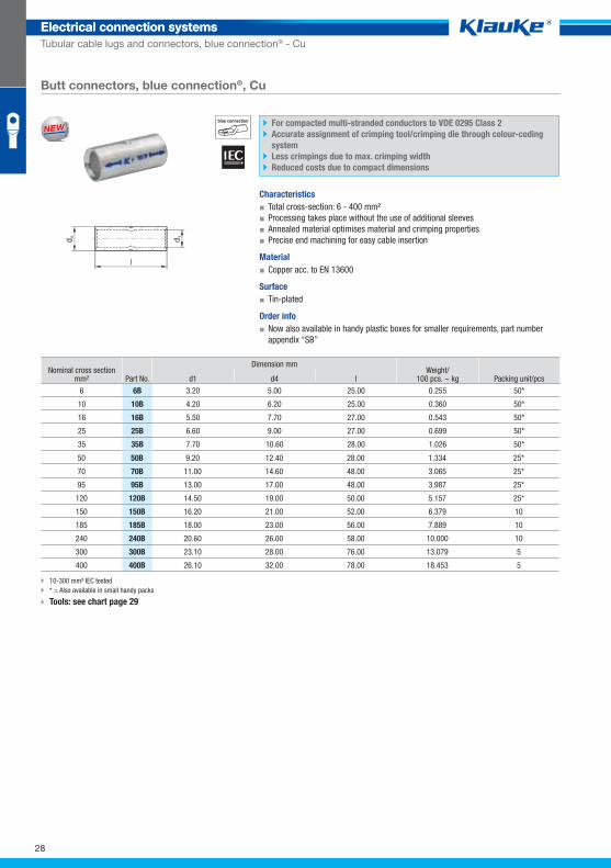
Butt connectors, blue connection®, Cu
blue connection For compacted multi-stranded conductors to VDE 0295 Class 2
Accurate assignment of crimping tool/crimping die through colour-coding
system
Less crimpings due to max. crimping width
Reduced costs due to compact dimensions
Characteristics
▪ Total cross-section: 6 - 400 mm²
▪ Processing takes place without the use of additional sleeves
▪ Annealed material optimises material and crimping properties
▪ Precise end machining for easy cable insertion
Material
▪ Copper acc. to EN 13600
Surface
▪ Tin-plated
Order info
▪ Now also available in handy plastic boxes for smaller requirements, part number
appendix “SB”
Nominal cross section mm² Part No.
Dimension mm Weight/
100 pcs. ~ kg Packing unit/pcs d1 d4 l
6 6B 3.20 5.00 25.00 0.255 50*
10 10B 4.20 6.20 25.00 0.360 50*
16 16B 5.50 7.70 27.00 0.543 50*
25 25B 6.60 9.00 27.00 0.699 50*
35 35B 7.70 10.60 28.00 1.026 50*
50 50B 9.20 12.40 28.00 1.334 25*
70 70B 11.00 14.60 48.00 3.065 25*
95 95B 13.00 17.00 48.00 3.987 25*
120 120B 14.50 19.00 50.00 5.157 25*
150 150B 16.20 21.00 52.00 6.379 10
185 185B 18.00 23.00 56.00 7.889 10
240 240B 20.60 26.00 58.00 10.000 10
300 300B 23.10 28.00 76.00 13.079 5
400 400B 26.10 32.00 78.00 18.453 5
WW
28
Klauke_Hauptkatalog_ElektrVerbindungstechnik_01_RohrkabelschuhUndVerbinder-CU_GB.indd 28 10.10.2014 11:57:36
Electrical connection systemsElectrical connection systems
Tubular cable lugs and connectors, blue connection® - Cu
^WZT_RKS_blue_connection^
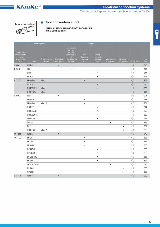
blue connection � Tool application chart
Tubular cable lugs and butt connectorsblue connection©
Crimping tools Tool type
Crimping rangecorresponds to
nominalcross-section
mm² ToolsCrimping head/
AdapterMechanical
crimping tools
mechanical,electrical,
pneumatic, crimping tools
with interchangeable
dies/heads
Handhydraulic crimping
tools
Batterypowered crimping
toolsHydraulic crim-ping systems
Hydraulic crim-ping heads Crimp profile
Page(Tool)
6-50 K05BC • 246
6-150 K354 • 260
EK354 • 314
EK354L • 316
6-240 HK60UNV +UA5 • 354
EK505L • 318
EKM60UNVL +UA5 • 356
EK60UNVL +UA5 • 357
6-300 K22 • 264
HK6022 • 288
HK60UNV +UA22 • 354
EK6022L • 324
EKM6022L • 322
EKM60UNVL • 356
EK60UNVL • 357
THK22 • 364
PK22 • 364
PK60UNV +UA22 • 355
10-120 K06BC • 249
16-400 HK12030 • 292
HK12042 • 294
HK120U • 296
EK12030L • 330
EK12042L • 332
EK120UNVL • 358
EK120UL • 334
HK122EL380 • 390
PK12042 • 368
PK120U • 370
25-150 K09BC • 250
29
Klauke Hauptkatalog EN_DIN A5.indb 29 07.10.2014 12:16:12
◾ Extensive product range for low and
medium-voltage applications.
◾ Distinct chamfer for easy entry of the
conductor, burr-free edges.
◾ Consistent precision, high safety and rating
properties thanks to high-quality pure
electrolytic copper.
◾ Klauke coding system with manufacturer’s
identifi cation, nominal cross-section and
hole size.
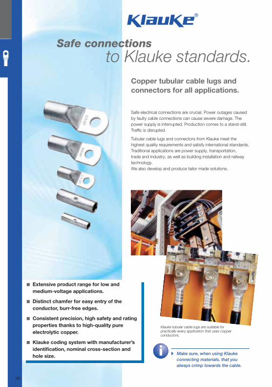
Safe connections to Klauke standards.
Copper tubular cable lugs and
connectors for all applications.
▸ Make sure, when using Klauke
connecting materials, that you
always crimp towards the cable.
Safe electrical connections are crucial. Power outages caused
by faulty cable connections can cause severe damage. The
power supply is interrupted. Production comes to a stand-still.
Traffi c is disrupted.
Tubular cable lugs and connectors from Klauke meet the
highest quality requirements and satisfy international standards.
Traditional applications are power supply, transportation,
trade and industry, as well as building installation and railway
technology.
We also develop and produce tailor made solutions.
Klauke tubular cable lugs are suitable for practically every application that uses copper conductors.
30
Klauke Hauptkatalog EN_DIN A5.indb 30 07.10.2014 12:16:12
■ Hold even under strong and severe vibrations.
▸ Consistent material thickness, precise diameters and an
accurate fi t mean optimised processing and ultimate safety.
▸ Tested to DIN EN 61373 Class 1B “Railway applications”.
Benefi ts:
▸ With professional installation of the correct types, optimised
stability even with mechanically stressed or severely vibrating
connections.
▸ Less repair and maintenance.
▸ Safe connections even under high load, e.g. in public
transport services.
■ Connections with system for every application.
▸ Products to Klauke standards in various designs and shapes.
▸ To international standards such as IEC, UL, DNV and German Lloyd.
▸ Solutions for cables with compacted round conductors, cables with
sector-shaped conductors and to suit individual requirements.
▸ Plus all corresponding manual and hydraulic crimping tools.
Benefi ts:
▸ The right products for every installation scenario.
▸ Highest fl exibility for connecting cables.
▸ Standards-compliance permits international application.
▸ A single source for everything – from cable lugs to tools.
▸ Guarantees the correct tools for professional
electrical installation. ▸ More from
Page 218.
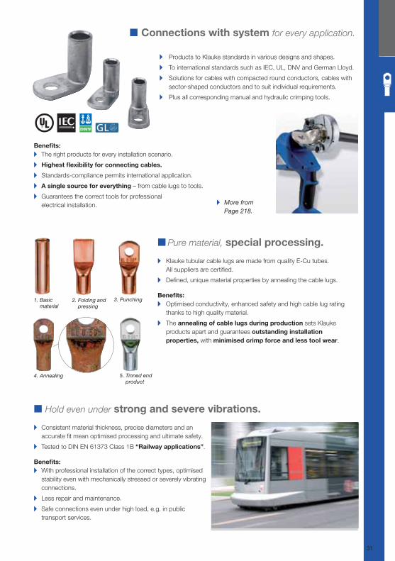
■ Pure material, special processing.
▸ Klauke tubular cable lugs are made from quality E-Cu tubes.
All suppliers are certifi ed.
▸ Defi ned, unique material properties by annealing the cable lugs.
Benefi ts:
▸ Optimised conductivity, enhanced safety and high cable lug rating
thanks to high quality material.
▸ The annealing of cable lugs during production sets Klauke
products apart and guarantees outstanding installation
properties, with minimised crimp force and less tool wear.
1. Basic material
2. Folding and pressing
3. Punching
4. Annealing 5. Tinned end product
31
Klauke Hauptkatalog EN_DIN A5.indb 31 07.10.2014 12:16:14
91r3grp
Electrical connection systemsElectrical connection systems
Copper tubular cable lugs and connectors - Cu
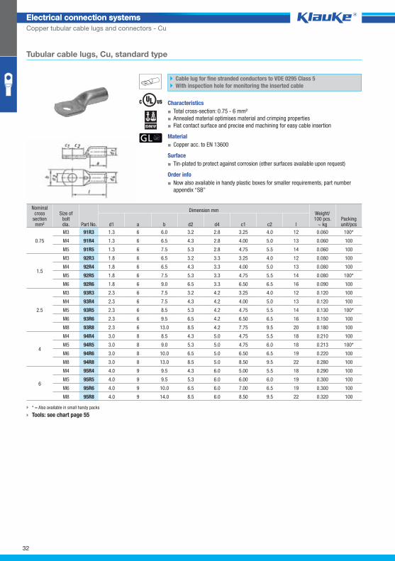
Tubular cable lugs, Cu, standard type
Cable lug for fine stranded conductors to VDE 0295 Class 5
With inspection hole for monitoring the inserted cable
Characteristics
▪ Total cross-section: 0.75 - 6 mm²
▪ Annealed material optimises material and crimping properties
▪ Flat contact surface and precise end machining for easy cable insertion
Material
▪ Copper acc. to EN 13600
Surface
▪ Tin-plated to protect against corrosion (other surfaces available upon request)
Order info
▪ Now also available in handy plastic boxes for smaller requirements, part number
appendix “SB”
Nominal cross
section mm²
Size ofboltdia.
Dimension mm Weight/100 pcs.
~ kg Packing unit/pcs Part No. d1 a b d2 d4 c1 c2 l
0.75
M3 91R3 1.3 6 6.0 3.2 2.8 3.25 4.0 12 0.060 100*
M4 91R4 1.3 6 6.5 4.3 2.8 4.00 5.0 13 0.060 100
M5 91R5 1.3 6 7.5 5.3 2.8 4.75 5.5 14 0.060 100
1.5
M3 92R3 1.8 6 6.5 3.2 3.3 3.25 4.0 12 0.080 100
M4 92R4 1.8 6 6.5 4.3 3.3 4.00 5.0 13 0.080 100
M5 92R5 1.8 6 7.5 5.3 3.3 4.75 5.5 14 0.080 100*
M6 92R6 1.8 6 9.0 6.5 3.3 6.50 6.5 16 0.090 100
2.5
M3 93R3 2.3 6 7.5 3.2 4.2 3.25 4.0 12 0.120 100
M4 93R4 2.3 6 7.5 4.3 4.2 4.00 5.0 13 0.120 100
M5 93R5 2.3 6 8.5 5.3 4.2 4.75 5.5 14 0.130 100*
M6 93R6 2.3 6 9.5 6.5 4.2 6.50 6.5 16 0.150 100
M8 93R8 2.3 6 13.0 8.5 4.2 7.75 9.5 20 0.180 100
4
M4 94R4 3.0 8 8.5 4.3 5.0 4.75 5.5 18 0.210 100
M5 94R5 3.0 8 9.0 5.3 5.0 4.75 6.0 18 0.213 100*
M6 94R6 3.0 8 10.0 6.5 5.0 6.50 6.5 19 0.220 100
M8 94R8 3.0 8 13.0 8.5 5.0 8.50 9.5 22 0.280 100
6
M4 95R4 4.0 9 9.5 4.3 6.0 5.00 5.5 18 0.290 100
M5 95R5 4.0 9 9.5 5.3 6.0 6.00 6.0 19 0.300 100
M6 95R6 4.0 9 10.0 6.5 6.0 7.00 6.5 19 0.300 100
M8 95R8 4.0 9 14.0 8.5 6.0 8.50 9.5 22 0.320 100
* = Also available in small handy packs
Tools: see chart page 55
32
Klauke Hauptkatalog EN_DIN A5.indb 32 07.10.2014 12:16:16
91c3grp
Electrical connection systemsElectrical connection systems
Copper tubular cable lugs and connectors - Cu
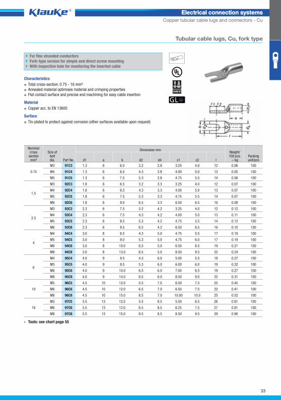
Tubular cable lugs, Cu, fork type
For fine stranded conductors
Fork-type version for simple and direct screw mounting
With inspection hole for monitoring the inserted cable
Characteristics
▪ Total cross-section: 0.75 - 16 mm²
▪ Annealed material optimises material and crimping properties
▪ Flat contact surface and precise end machining for easy cable insertion
Material
▪ Copper acc. to EN 13600
Surface
▪ Tin-plated to protect against corrosion (other surfaces available upon request)
Nominal cross
section mm²
Size ofboltdia.
Dimension mm Weight/100 pcs.
~ kg Packing unit/pcs Part No. d1 a b d2 d4 c1 c2 l
0.75
M3 91C3 1.3 6 6.0 3.2 2.8 3.25 4.0 12 0.06 100
M4 91C4 1.3 6 6.5 4.3 2.8 4.00 5.0 13 0.05 100
M5 91C5 1.3 6 7.5 5.3 2.8 4.75 5.5 14 0.06 100
1.5
M3 92C3 1.8 6 6.5 3.2 3.3 3.25 4.0 12 0.07 100
M4 92C4 1.8 6 6.5 4.3 3.3 4.00 5.0 13 0.07 100
M5 92C5 1.8 6 7.5 5.3 3.3 4.75 5.5 14 0.07 100
M6 92C6 1.8 6 9.0 6.5 3.3 6.50 6.5 16 0.08 100
2.5
M3 93C3 2.3 6 7.5 3.2 4.2 3.25 4.0 12 0.12 100
M4 93C4 2.3 6 7.5 4.3 4.2 4.00 5.0 13 0.11 100
M5 93C5 2.3 6 8.5 5.3 4.2 4.75 5.5 14 0.12 100
M6 93C6 2.3 6 9.5 6.5 4.2 6.50 6.5 16 0.10 100
4
M4 94C4 3.0 8 8.5 4.3 5.0 4.75 5.5 17 0.19 100
M5 94C5 3.0 8 9.0 5.3 5.0 4.75 6.0 17 0.19 100
M6 94C6 3.0 8 10.0 6.5 5.0 6.50 6.5 19 0.21 100
M8 94C8 3.0 8 13.0 8.5 5.0 8.50 9.5 22 0.24 100
6
M4 95C4 4.0 9 9.5 4.3 6.0 5.00 5.5 18 0.27 100
M5 95C5 4.0 9 9.5 5.3 6.0 6.00 6.0 19 0.32 100
M6 95C6 4.0 9 10.0 6.5 6.0 7.00 6.5 19 0.27 100
M8 95C8 4.0 9 14.0 8.5 6.0 8.50 9.0 22 0.31 100
10
M5 96C5 4.5 10 12.0 5.5 7.0 6.50 7.5 22 0.45 100
M6 96C6 4.5 10 12.0 6.5 7.0 6.50 7.5 22 0.41 100
M8 96C8 4.5 10 15.0 8.5 7.0 10.00 10.0 25 0.52 100
16
M5 97C5 5.5 13 12.0 5.5 8.5 5.50 6.5 26 0.81 100
M6 97C6 5.5 13 12.0 6.5 8.5 6.25 7.5 27 0.81 100
M8 97C8 5.5 13 15.0 8.5 8.5 8.50 9.5 29 0.90 100
Tools: see chart page 55
33
Klauke Hauptkatalog EN_DIN A5.indb 33 07.10.2014 12:16:16
1r5grp
Electrical connection systemsElectrical connection systems
Copper tubular cable lugs and connectors - Cu
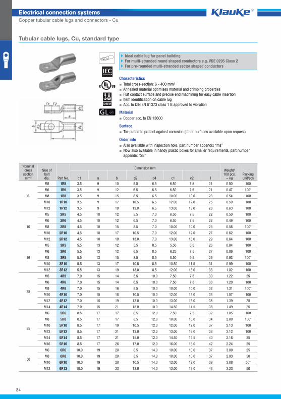
Tubular cable lugs, Cu, standard type
Ideal cable lug for panel building
For multi-stranded round shaped conductors e.g. VDE 0295 Class 2
For pre-rounded multi-stranded sector shaped conductors
Characteristics
▪ Total cross-section: 6 - 400 mm²
▪ Annealed material optimises material and crimping properties
▪ Flat contact surface and precise end machining for easy cable insertion
▪ Item identification on cable lug
▪ Acc. to DIN EN 61373 class 1 B approved to vibration
Material
▪ Copper acc. to EN 13600
Surface
▪ Tin-plated to protect against corrosion (other surfaces available upon request)
Order info
▪ Also available with inspection hole, part number appendix “ms”
▪ Now also available in handy plastic boxes for smaller requirements, part number
appendix “SB”
Nominal cross
section mm²
Size ofboltdia.
Dimension mm Weight/100 pcs.
~ kg Packing unit/pcs Part No. d1 a b d2 d4 c1 c2 l
6
M5 1R5 3.5 9 10 5.5 6.5 6.50 7.5 21 0.50 100
M6 1R6 3.5 9 12 6.5 6.5 6.50 7.5 21 0.47 100*
M8 1R8 3.5 9 15 8.5 6.5 10.00 10.0 23 0.54 100
M10 1R10 3.5 9 17 10.5 6.5 12.00 12.0 25 0.59 100
M12 1R12 3.5 9 19 13.0 6.5 13.00 13.0 28 0.63 100
10
M5 2R5 4.5 10 12 5.5 7.0 6.50 7.5 22 0.50 100
M6 2R6 4.5 10 12 6.5 7.0 6.50 7.5 22 0.49 100
M8 2R8 4.5 10 15 8.5 7.0 10.00 10.0 25 0.58 100*
M10 2R10 4.5 10 17 10.5 7.0 12.00 12.0 27 0.62 100
M12 2R12 4.5 10 19 13.0 7.0 13.00 13.0 29 0.64 100
16
M5 3R5 5.5 13 12 5.5 8.5 5.50 6.5 26 0.84 100
M6 3R6 5.5 13 12 6.5 8.5 6.25 7.5 27 0.86 100
M8 3R8 5.5 13 15 8.5 8.5 8.50 9.5 29 0.93 100*
M10 3R10 5.5 13 17 10.5 8.5 10.50 11.5 31 0.99 100
M12 3R12 5.5 13 19 13.0 8.5 12.00 13.0 33 1.02 100
25
M5 4R5 7.0 15 14 5.5 10.0 7.50 7.5 30 1.22 25
M6 4R6 7.0 15 14 6.5 10.0 7.50 7.5 30 1.20 100
M8 4R8 7.0 15 16 8.5 10.0 10.00 10.0 32 1.31 100*
M10 4R10 7.0 15 18 10.5 10.0 12.00 12.0 34 1.57 100
M12 4R12 7.0 15 19 13.0 10.0 13.00 13.0 35 1.39 25
M14 4R14 7.0 15 21 15.0 10.0 14.50 14.5 38 1.49 25
35
M6 5R6 8.5 17 17 6.5 12.0 7.50 7.5 32 1.85 100
M8 5R8 8.5 17 17 8.5 12.0 10.00 10.0 34 2.00 100*
M10 5R10 8.5 17 19 10.5 12.0 12.00 12.0 37 2.13 100
M12 5R12 8.5 17 21 13.0 12.0 13.00 13.0 38 2.12 100
M14 5R14 8.5 17 21 15.0 12.0 14.50 14.5 40 2.18 25
M16 5R16 8.5 17 26 17.0 12.0 16.00 16.0 42 2.24 25
50
M6 6R6 10.0 19 20 6.5 14.0 10.00 10.0 37 3.00 25
M8 6R8 10.0 19 20 8.5 14.0 10.00 10.0 37 2.93 50
M10 6R10 10.0 19 20 10.5 14.0 12.00 12.0 39 3.08 50*
M12 6R12 10.0 19 23 13.0 14.0 13.00 13.0 43 3.23 50
34
Klauke Hauptkatalog EN_DIN A5.indb 34 07.10.2014 12:16:17
Electrical connection systemsElectrical connection systems
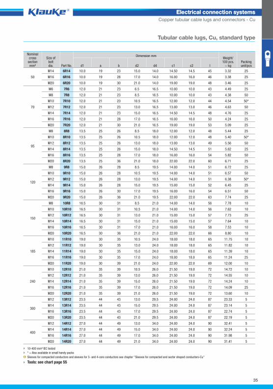
Copper tubular cable lugs and connectors - Cu
Tubular cable lugs, Cu, standard type
10-400 mm² IEC tested
* = Also available in small handy packs
Sleeves for compacted conductors and sleeves for 3- and 4-core conductors see chapter "Sleeves for compacted and sector shaped conductors-Cu"
Tools: see chart page 55
Nominal cross
section mm²
Size ofboltdia.
Dimension mm Weight/100 pcs.
~ kg Packing unit/pcs Part No. d1 a b d2 d4 c1 c2 l
50
M14 6R14 10.0 19 23 15.0 14.0 14.50 14.5 45 3.32 25
M16 6R16 10.0 19 28 17.0 14.0 16.00 16.0 46 3.38 25
M20 6R20 10.0 19 30 21.0 14.0 19.00 19.0 48 3.46 25
70
M6 7R6 12.0 21 23 6.5 16.5 10.00 10.0 43 4.49 25
M8 7R8 12.0 21 23 8.5 16.5 10.00 10.0 43 4.38 50
M10 7R10 12.0 21 23 10.5 16.5 12.00 12.0 44 4.54 50*
M12 7R12 12.0 21 23 13.0 16.5 13.00 13.0 46 4.63 50
M14 7R14 12.0 21 23 15.0 16.5 14.50 14.5 48 4.76 25
M16 7R16 12.0 21 28 17.0 16.5 16.00 16.0 50 4.24 25
M20 7R20 12.0 21 30 21.0 16.5 19.00 19.0 53 5.09 25
95
M8 8R8 13.5 25 26 8.5 18.0 12.00 12.0 48 5.44 25
M10 8R10 13.5 25 26 10.5 18.0 12.00 12.0 48 5.40 50*
M12 8R12 13.5 25 26 13.0 18.0 13.00 13.0 49 5.56 50
M14 8R14 13.5 25 26 15.0 18.0 14.50 14.5 51 5.62 25
M16 8R16 13.5 25 28 17.0 18.0 16.00 16.0 54 5.82 50
M20 8R20 13.5 25 36 21.0 18.0 22.00 22.0 60 6.71 25
120
M8 9R8 15.0 26 28 8.5 19.5 14.00 14.0 51 6.72 25
M10 9R10 15.0 26 28 10.5 19.5 14.00 14.0 51 6.57 50
M12 9R12 15.0 26 28 13.0 19.5 14.00 14.0 51 6.38 50*
M14 9R14 15.0 26 28 15.0 19.5 15.00 15.0 52 6.45 25
M16 9R16 15.0 26 30 17.0 19.5 16.00 16.0 54 6.51 50
M20 9R20 15.0 26 36 21.0 19.5 22.00 22.0 63 7.74 25
150
M8 10R8 16.5 30 31 8.5 21.0 14.00 14.0 56 7.78 10
M10 10R10 16.5 30 31 10.5 21.0 14.00 14.0 56 7.62 10
M12 10R12 16.5 30 31 13.0 21.0 15.00 15.0 57 7.73 25
M14 10R14 16.5 30 31 15.0 21.0 15.00 15.0 57 7.64 10
M16 10R16 16.5 30 31 17.0 21.0 16.00 16.0 58 7.53 10
M20 10R20 16.5 30 36 21.0 21.0 22.00 22.0 66 8.80 10
185
M10 11R10 19.0 30 35 10.5 24.0 18.00 18.0 65 11.75 10
M12 11R12 19.0 30 35 13.0 24.0 18.00 18.0 65 11.82 10
M14 11R14 19.0 30 35 15.0 24.0 18.00 18.0 65 11.39 10
M16 11R16 19.0 30 35 17.0 24.0 18.00 18.0 65 11.24 25
M20 11R20 19.0 30 39 21.0 24.0 22.00 22.0 69 12.00 10
240
M10 12R10 21.0 35 39 10.5 26.0 21.50 19.0 72 14.72 10
M12 12R12 21.0 35 39 13.0 26.0 21.50 19.0 72 14.55 10
M14 12R14 21.0 35 39 15.0 26.0 21.50 19.0 72 14.24 10
M16 12R16 21.0 35 39 17.0 26.0 21.50 19.0 72 14.09 25
M20 12R20 21.0 35 39 21.0 26.0 21.50 19.0 72 13.60 10
300
M12 13R12 23.5 44 43 13.0 29.5 24.00 24.0 87 23.33 5
M14 13R14 23.5 44 43 15.0 29.5 24.00 24.0 87 23.14 5
M16 13R16 23.5 44 43 17.0 29.5 24.00 24.0 87 22.74 5
M20 13R20 23.5 44 43 21.0 29.5 24.00 24.0 87 22.19 5
400
M12 14R12 27.0 44 49 13.0 34.0 24.00 24.0 90 32.41 5
M14 14R14 27.0 44 49 15.0 34.0 24.00 24.0 90 32.24 5
M16 14R16 27.0 44 49 17.0 34.0 24.00 24.0 90 31.98 5
M20 14R20 27.0 44 49 21.0 34.0 24.00 24.0 90 31.41 5
35
Klauke Hauptkatalog EN_DIN A5.indb 35 07.10.2014 12:16:17
41r5grp
Electrical connection systemsElectrical connection systems
Copper tubular cable lugs and connectors - Cu
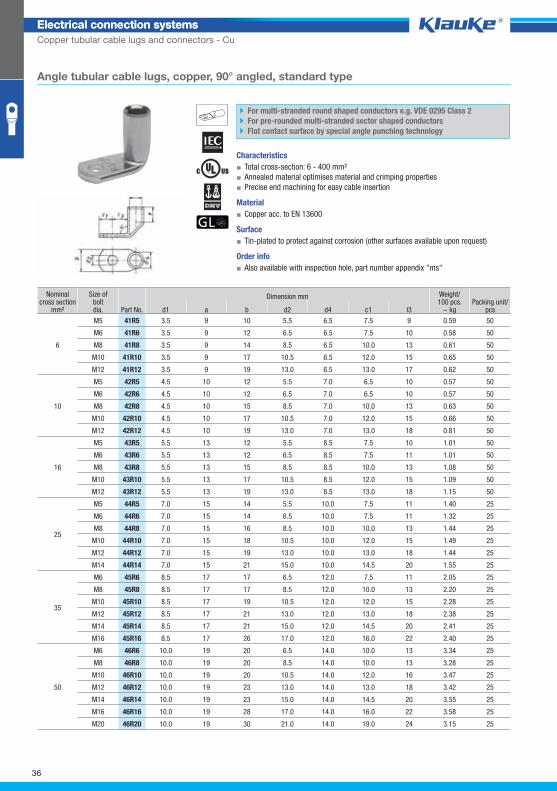
Angle tubular cable lugs, copper, 90° angled, standard type
For multi-stranded round shaped conductors e.g. VDE 0295 Class 2
For pre-rounded multi-stranded sector shaped conductors
Flat contact surface by special angle punching technology
Characteristics
▪ Total cross-section: 6 - 400 mm²
▪ Annealed material optimises material and crimping properties
▪ Precise end machining for easy cable insertion
Material
▪ Copper acc. to EN 13600
Surface
▪ Tin-plated to protect against corrosion (other surfaces available upon request)
Order info
▪ Also available with inspection hole, part number appendix "ms"
Nominal cross section
mm²
Size ofboltdia.
Dimension mm Weight/100 pcs.
~ kg Packing unit/
pcs Part No. d1 a b d2 d4 c1 l3
6
M5 41R5 3.5 9 10 5.5 6.5 7.5 9 0.59 50
M6 41R6 3.5 9 12 6.5 6.5 7.5 10 0.58 50
M8 41R8 3.5 9 14 8.5 6.5 10.0 13 0.61 50
M10 41R10 3.5 9 17 10.5 6.5 12.0 15 0.65 50
M12 41R12 3.5 9 19 13.0 6.5 13.0 17 0.62 50
10
M5 42R5 4.5 10 12 5.5 7.0 6.5 10 0.57 50
M6 42R6 4.5 10 12 6.5 7.0 6.5 10 0.57 50
M8 42R8 4.5 10 15 8.5 7.0 10.0 13 0.63 50
M10 42R10 4.5 10 17 10.5 7.0 12.0 15 0.66 50
M12 42R12 4.5 10 19 13.0 7.0 13.0 18 0.81 50
16
M5 43R5 5.5 13 12 5.5 8.5 7.5 10 1.01 50
M6 43R6 5.5 13 12 6.5 8.5 7.5 11 1.01 50
M8 43R8 5.5 13 15 8.5 8.5 10.0 13 1.08 50
M10 43R10 5.5 13 17 10.5 8.5 12.0 15 1.09 50
M12 43R12 5.5 13 19 13.0 8.5 13.0 18 1.15 50
25
M5 44R5 7.0 15 14 5.5 10.0 7.5 11 1.40 25
M6 44R6 7.0 15 14 6.5 10.0 7.5 11 1.32 25
M8 44R8 7.0 15 16 8.5 10.0 10.0 13 1.44 25
M10 44R10 7.0 15 18 10.5 10.0 12.0 15 1.49 25
M12 44R12 7.0 15 19 13.0 10.0 13.0 18 1.44 25
M14 44R14 7.0 15 21 15.0 10.0 14.5 20 1.55 25
35
M6 45R6 8.5 17 17 6.5 12.0 7.5 11 2.05 25
M8 45R8 8.5 17 17 8.5 12.0 10.0 13 2.20 25
M10 45R10 8.5 17 19 10.5 12.0 12.0 15 2.28 25
M12 45R12 8.5 17 21 13.0 12.0 13.0 18 2.38 25
M14 45R14 8.5 17 21 15.0 12.0 14.5 20 2.41 25
M16 45R16 8.5 17 26 17.0 12.0 16.0 22 2.40 25
50
M6 46R6 10.0 19 20 6.5 14.0 10.0 13 3.34 25
M8 46R8 10.0 19 20 8.5 14.0 10.0 13 3.28 25
M10 46R10 10.0 19 20 10.5 14.0 12.0 16 3.47 25
M12 46R12 10.0 19 23 13.0 14.0 13.0 18 3.42 25
M14 46R14 10.0 19 23 15.0 14.0 14.5 20 3.55 25
M16 46R16 10.0 19 28 17.0 14.0 16.0 22 3.58 25
M20 46R20 10.0 19 30 21.0 14.0 19.0 24 3.15 25
36
Klauke Hauptkatalog EN_DIN A5.indb 36 07.10.2014 12:16:18
Electrical connection systemsElectrical connection systems
Copper tubular cable lugs and connectors - Cu
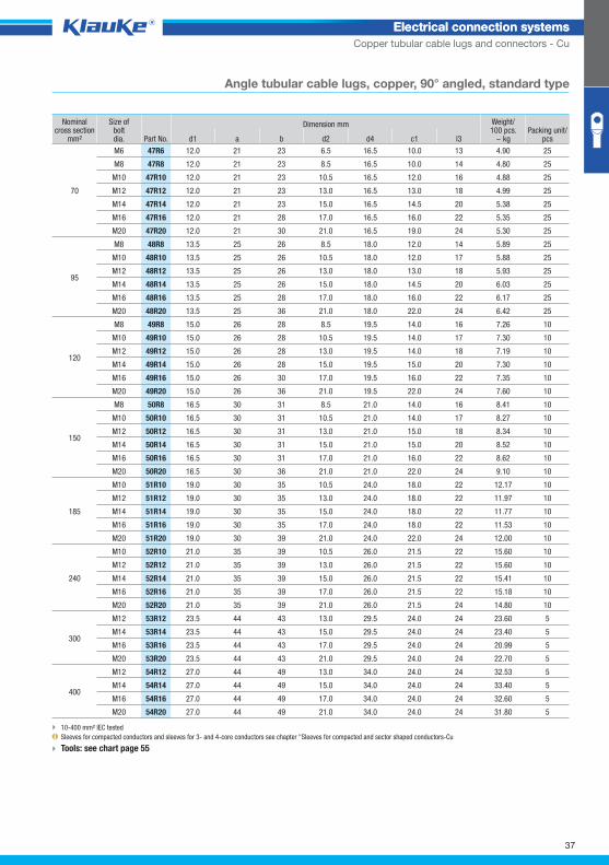
Angle tubular cable lugs, copper, 90° angled, standard type
Nominal cross section
mm²
Size ofboltdia.
Dimension mm Weight/100 pcs.
~ kg Packing unit/
pcs Part No. d1 a b d2 d4 c1 l3
70
M6 47R6 12.0 21 23 6.5 16.5 10.0 13 4.90 25
M8 47R8 12.0 21 23 8.5 16.5 10.0 14 4.80 25
M10 47R10 12.0 21 23 10.5 16.5 12.0 16 4.88 25
M12 47R12 12.0 21 23 13.0 16.5 13.0 18 4.99 25
M14 47R14 12.0 21 23 15.0 16.5 14.5 20 5.38 25
M16 47R16 12.0 21 28 17.0 16.5 16.0 22 5.35 25
M20 47R20 12.0 21 30 21.0 16.5 19.0 24 5.30 25
95
M8 48R8 13.5 25 26 8.5 18.0 12.0 14 5.89 25
M10 48R10 13.5 25 26 10.5 18.0 12.0 17 5.88 25
M12 48R12 13.5 25 26 13.0 18.0 13.0 18 5.93 25
M14 48R14 13.5 25 26 15.0 18.0 14.5 20 6.03 25
M16 48R16 13.5 25 28 17.0 18.0 16.0 22 6.17 25
M20 48R20 13.5 25 36 21.0 18.0 22.0 24 6.42 25
120
M8 49R8 15.0 26 28 8.5 19.5 14.0 16 7.26 10
M10 49R10 15.0 26 28 10.5 19.5 14.0 17 7.30 10
M12 49R12 15.0 26 28 13.0 19.5 14.0 18 7.19 10
M14 49R14 15.0 26 28 15.0 19.5 15.0 20 7.30 10
M16 49R16 15.0 26 30 17.0 19.5 16.0 22 7.35 10
M20 49R20 15.0 26 36 21.0 19.5 22.0 24 7.60 10
150
M8 50R8 16.5 30 31 8.5 21.0 14.0 16 8.41 10
M10 50R10 16.5 30 31 10.5 21.0 14.0 17 8.27 10
M12 50R12 16.5 30 31 13.0 21.0 15.0 18 8.34 10
M14 50R14 16.5 30 31 15.0 21.0 15.0 20 8.52 10
M16 50R16 16.5 30 31 17.0 21.0 16.0 22 8.62 10
M20 50R20 16.5 30 36 21.0 21.0 22.0 24 9.10 10
185
M10 51R10 19.0 30 35 10.5 24.0 18.0 22 12.17 10
M12 51R12 19.0 30 35 13.0 24.0 18.0 22 11.97 10
M14 51R14 19.0 30 35 15.0 24.0 18.0 22 11.77 10
M16 51R16 19.0 30 35 17.0 24.0 18.0 22 11.53 10
M20 51R20 19.0 30 39 21.0 24.0 22.0 24 12.00 10
240
M10 52R10 21.0 35 39 10.5 26.0 21.5 22 15.60 10
M12 52R12 21.0 35 39 13.0 26.0 21.5 22 15.60 10
M14 52R14 21.0 35 39 15.0 26.0 21.5 22 15.41 10
M16 52R16 21.0 35 39 17.0 26.0 21.5 22 15.18 10
M20 52R20 21.0 35 39 21.0 26.0 21.5 24 14.80 10
300
M12 53R12 23.5 44 43 13.0 29.5 24.0 24 23.60 5
M14 53R14 23.5 44 43 15.0 29.5 24.0 24 23.40 5
M16 53R16 23.5 44 43 17.0 29.5 24.0 24 20.99 5
M20 53R20 23.5 44 43 21.0 29.5 24.0 24 22.70 5
400
M12 54R12 27.0 44 49 13.0 34.0 24.0 24 32.53 5
M14 54R14 27.0 44 49 15.0 34.0 24.0 24 33.40 5
M16 54R16 27.0 44 49 17.0 34.0 24.0 24 32.60 5
M20 54R20 27.0 44 49 21.0 34.0 24.0 24 31.80 5
10-400 mm² IEC tested
Sleeves for compacted conductors and sleeves for 3- and 4-core conductors see chapter "Sleeves for compacted and sector shaped conductors-Cu
Tools: see chart page 55
37
Klauke Hauptkatalog EN_DIN A5.indb 37 07.10.2014 12:16:18
41r545grp
Electrical connection systemsElectrical connection systems
Copper tubular cable lugs and connectors - Cu
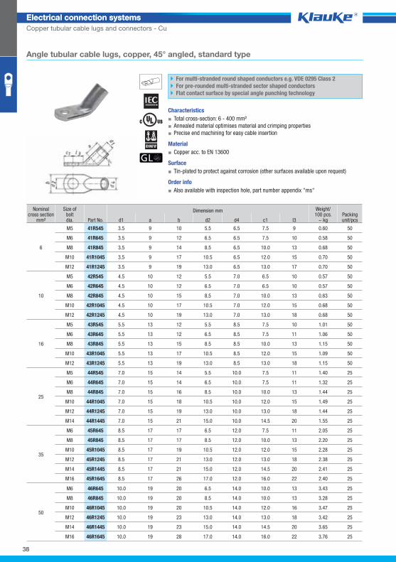
Angle tubular cable lugs, copper, 45° angled, standard type
For multi-stranded round shaped conductors e.g. VDE 0295 Class 2
For pre-rounded multi-stranded sector shaped conductors
Flat contact surface by special angle punching technology
Characteristics
▪ Total cross-section: 6 - 400 mm²
▪ Annealed material optimises material and crimping properties
▪ Precise end machining for easy cable insertion
Material
▪ Copper acc. to EN 13600
Surface
▪ Tin-plated to protect against corrosion (other surfaces available upon request)
Order info
▪ Also available with inspection hole, part number appendix "ms"
Nominal cross section
mm²
Size ofboltdia.
Dimension mm Weight/100 pcs.
~ kg Packing unit/pcs Part No. d1 a b d2 d4 c1 l3
6
M5 41R545 3.5 9 10 5.5 6.5 7.5 9 0.60 50
M6 41R645 3.5 9 12 6.5 6.5 7.5 10 0.58 50
M8 41R845 3.5 9 14 8.5 6.5 10.0 13 0.68 50
M10 41R1045 3.5 9 17 10.5 6.5 12.0 15 0.70 50
M12 41R1245 3.5 9 19 13.0 6.5 13.0 17 0.70 50
10
M5 42R545 4.5 10 12 5.5 7.0 6.5 10 0.57 50
M6 42R645 4.5 10 12 6.5 7.0 6.5 10 0.57 50
M8 42R845 4.5 10 15 8.5 7.0 10.0 13 0.63 50
M10 42R1045 4.5 10 17 10.5 7.0 12.0 15 0.68 50
M12 42R1245 4.5 10 19 13.0 7.0 13.0 18 0.68 50
16
M5 43R545 5.5 13 12 5.5 8.5 7.5 10 1.01 50
M6 43R645 5.5 13 12 6.5 8.5 7.5 11 1.06 50
M8 43R845 5.5 13 15 8.5 8.5 10.0 13 1.15 50
M10 43R1045 5.5 13 17 10.5 8.5 12.0 15 1.09 50
M12 43R1245 5.5 13 19 13.0 8.5 13.0 18 1.15 50
25
M5 44R545 7.0 15 14 5.5 10.0 7.5 11 1.40 25
M6 44R645 7.0 15 14 6.5 10.0 7.5 11 1.32 25
M8 44R845 7.0 15 16 8.5 10.0 10.0 13 1.44 25
M10 44R1045 7.0 15 18 10.5 10.0 12.0 15 1.49 25
M12 44R1245 7.0 15 19 13.0 10.0 13.0 18 1.44 25
M14 44R1445 7.0 15 21 15.0 10.0 14.5 20 1.55 25
35
M6 45R645 8.5 17 17 6.5 12.0 7.5 11 2.05 25
M8 45R845 8.5 17 17 8.5 12.0 10.0 13 2.20 25
M10 45R1045 8.5 17 19 10.5 12.0 12.0 15 2.28 25
M12 45R1245 8.5 17 21 13.0 12.0 13.0 18 2.38 25
M14 45R1445 8.5 17 21 15.0 12.0 14.5 20 2.41 25
M16 45R1645 8.5 17 26 17.0 12.0 16.0 22 2.40 25
50
M6 46R645 10.0 19 20 6.5 14.0 10.0 13 3.43 25
M8 46R845 10.0 19 20 8.5 14.0 10.0 13 3.28 25
M10 46R1045 10.0 19 20 10.5 14.0 12.0 16 3.47 25
M12 46R1245 10.0 19 23 13.0 14.0 13.0 18 3.42 25
M14 46R1445 10.0 19 23 15.0 14.0 14.5 20 3.65 25
M16 46R1645 10.0 19 28 17.0 14.0 16.0 22 3.76 25
38
Klauke Hauptkatalog EN_DIN A5.indb 38 07.10.2014 12:16:18
Electrical connection systemsElectrical connection systems
Copper tubular cable lugs and connectors - Cu
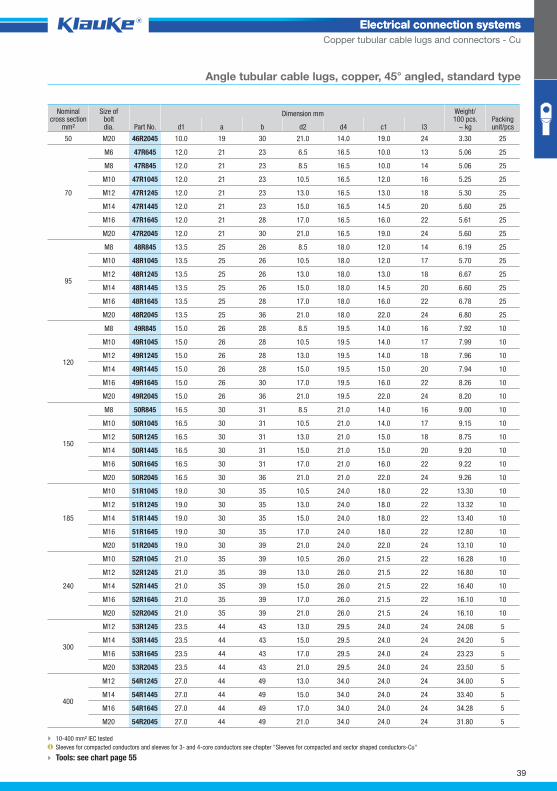
Angle tubular cable lugs, copper, 45° angled, standard type
Nominal cross section
mm²
Size ofboltdia.
Dimension mm Weight/100 pcs.
~ kg Packing unit/pcs Part No. d1 a b d2 d4 c1 l3
50 M20 46R2045 10.0 19 30 21.0 14.0 19.0 24 3.30 25
70
M6 47R645 12.0 21 23 6.5 16.5 10.0 13 5.06 25
M8 47R845 12.0 21 23 8.5 16.5 10.0 14 5.06 25
M10 47R1045 12.0 21 23 10.5 16.5 12.0 16 5.25 25
M12 47R1245 12.0 21 23 13.0 16.5 13.0 18 5.30 25
M14 47R1445 12.0 21 23 15.0 16.5 14.5 20 5.60 25
M16 47R1645 12.0 21 28 17.0 16.5 16.0 22 5.61 25
M20 47R2045 12.0 21 30 21.0 16.5 19.0 24 5.60 25
95
M8 48R845 13.5 25 26 8.5 18.0 12.0 14 6.19 25
M10 48R1045 13.5 25 26 10.5 18.0 12.0 17 5.70 25
M12 48R1245 13.5 25 26 13.0 18.0 13.0 18 6.67 25
M14 48R1445 13.5 25 26 15.0 18.0 14.5 20 6.60 25
M16 48R1645 13.5 25 28 17.0 18.0 16.0 22 6.78 25
M20 48R2045 13.5 25 36 21.0 18.0 22.0 24 6.80 25
120
M8 49R845 15.0 26 28 8.5 19.5 14.0 16 7.92 10
M10 49R1045 15.0 26 28 10.5 19.5 14.0 17 7.99 10
M12 49R1245 15.0 26 28 13.0 19.5 14.0 18 7.96 10
M14 49R1445 15.0 26 28 15.0 19.5 15.0 20 7.94 10
M16 49R1645 15.0 26 30 17.0 19.5 16.0 22 8.26 10
M20 49R2045 15.0 26 36 21.0 19.5 22.0 24 8.20 10
150
M8 50R845 16.5 30 31 8.5 21.0 14.0 16 9.00 10
M10 50R1045 16.5 30 31 10.5 21.0 14.0 17 9.15 10
M12 50R1245 16.5 30 31 13.0 21.0 15.0 18 8.75 10
M14 50R1445 16.5 30 31 15.0 21.0 15.0 20 9.20 10
M16 50R1645 16.5 30 31 17.0 21.0 16.0 22 9.22 10
M20 50R2045 16.5 30 36 21.0 21.0 22.0 24 9.26 10
185
M10 51R1045 19.0 30 35 10.5 24.0 18.0 22 13.30 10
M12 51R1245 19.0 30 35 13.0 24.0 18.0 22 13.32 10
M14 51R1445 19.0 30 35 15.0 24.0 18.0 22 13.40 10
M16 51R1645 19.0 30 35 17.0 24.0 18.0 22 12.80 10
M20 51R2045 19.0 30 39 21.0 24.0 22.0 24 13.10 10
240
M10 52R1045 21.0 35 39 10.5 26.0 21.5 22 16.28 10
M12 52R1245 21.0 35 39 13.0 26.0 21.5 22 16.80 10
M14 52R1445 21.0 35 39 15.0 26.0 21.5 22 16.40 10
M16 52R1645 21.0 35 39 17.0 26.0 21.5 22 16.10 10
M20 52R2045 21.0 35 39 21.0 26.0 21.5 24 16.10 10
300
M12 53R1245 23.5 44 43 13.0 29.5 24.0 24 24.08 5
M14 53R1445 23.5 44 43 15.0 29.5 24.0 24 24.20 5
M16 53R1645 23.5 44 43 17.0 29.5 24.0 24 23.23 5
M20 53R2045 23.5 44 43 21.0 29.5 24.0 24 23.50 5
400
M12 54R1245 27.0 44 49 13.0 34.0 24.0 24 34.00 5
M14 54R1445 27.0 44 49 15.0 34.0 24.0 24 33.40 5
M16 54R1645 27.0 44 49 17.0 34.0 24.0 24 34.28 5
M20 54R2045 27.0 44 49 21.0 34.0 24.0 24 31.80 5
10-400 mm² IEC tested
Sleeves for compacted conductors and sleeves for 3- and 4-core conductors see chapter "Sleeves for compacted and sector shaped conductors-Cu"
Tools: see chart page 55
39
Klauke Hauptkatalog EN_DIN A5.indb 39 07.10.2014 12:16:19
17rgrp
Electrical connection systemsElectrical connection systems
Copper tubular cable lugs and connectors - Cu
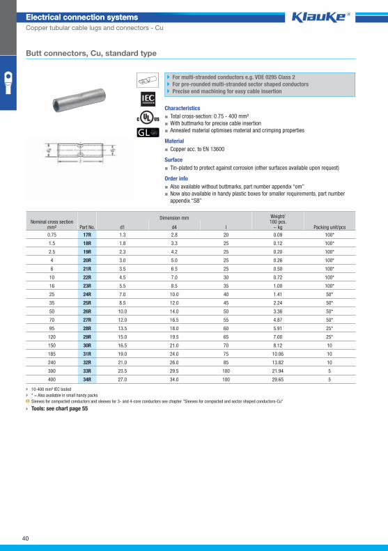
Butt connectors, Cu, standard type
For multi-stranded conductors e.g. VDE 0295 Class 2
For pre-rounded multi-stranded sector shaped conductors
Precise end machining for easy cable insertion
Characteristics
▪ Total cross-section: 0.75 - 400 mm²
▪ With buttmarks for precise cable insertion
▪ Annealed material optimises material and crimping properties
Material
▪ Copper acc. to EN 13600
Surface
▪ Tin-plated to protect against corrosion (other surfaces available upon request)
Order info
▪ Also available without buttmarks, part number appendix “om”
▪ Now also available in handy plastic boxes for smaller requirements, part number
appendix “SB”
Nominal cross section mm² Part No.
Dimension mm Weight/100 pcs.
~ kg Packing unit/pcs d1 d4 l
0.75 17R 1.3 2.8 20 0.09 100*
1.5 18R 1.8 3.3 25 0.12 100*
2.5 19R 2.3 4.2 25 0.20 100*
4 20R 3.0 5.0 25 0.26 100*
6 21R 3.5 6.5 25 0.50 100*
10 22R 4.5 7.0 30 0.72 100*
16 23R 5.5 8.5 35 1.00 100*
25 24R 7.0 10.0 40 1.41 50*
35 25R 8.5 12.0 45 2.24 50*
50 26R 10.0 14.0 50 3.36 50*
70 27R 12.0 16.5 55 4.87 50*
95 28R 13.5 18.0 60 5.91 25*
120 29R 15.0 19.5 65 7.00 25*
150 30R 16.5 21.0 70 8.12 10
185 31R 19.0 24.0 75 10.06 10
240 32R 21.0 26.0 85 13.82 10
300 33R 23.5 29.5 100 21.94 5
400 34R 27.0 34.0 100 29.65 5
10-400 mm² IEC tested
* = Also available in small handy packs
Sleeves for compacted conductors and sleeves for 3- and 4-core conductors see chapter "Sleeves for compacted and sector shaped conductors-Cu"
Tools: see chart page 55
40
Klauke Hauptkatalog EN_DIN A5.indb 40 07.10.2014 12:16:19
148rgrp
Electrical connection systemsElectrical connection systems
Copper tubular cable lugs and connectors - Cu
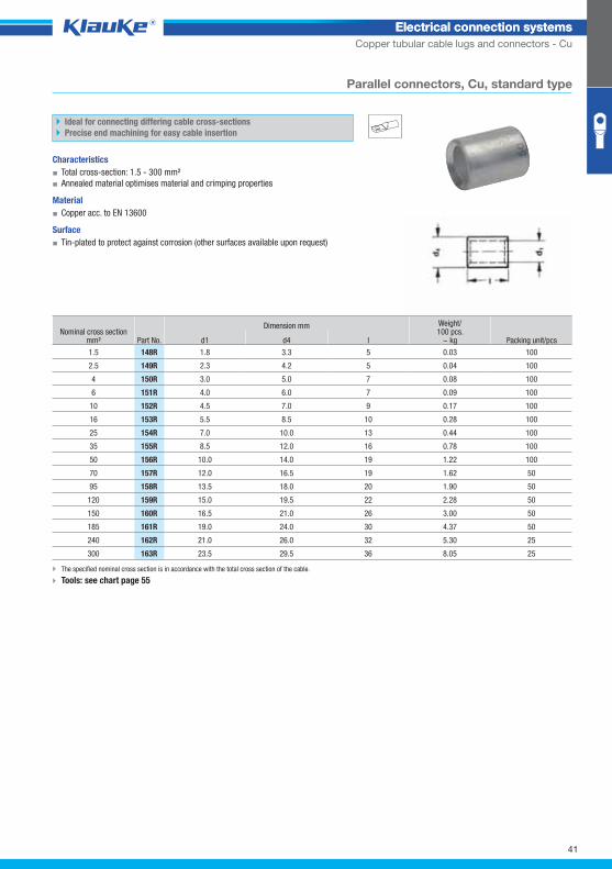
Parallel connectors, Cu, standard type
Ideal for connecting differing cable cross-sections
Precise end machining for easy cable insertion
Characteristics
▪ Total cross-section: 1.5 - 300 mm²
▪ Annealed material optimises material and crimping properties
Material
▪ Copper acc. to EN 13600
Surface
▪ Tin-plated to protect against corrosion (other surfaces available upon request)
Nominal cross section mm² Part No.
Dimension mm Weight/100 pcs.
~ kg Packing unit/pcs d1 d4 l
1.5 148R 1.8 3.3 5 0.03 100
2.5 149R 2.3 4.2 5 0.04 100
4 150R 3.0 5.0 7 0.08 100
6 151R 4.0 6.0 7 0.09 100
10 152R 4.5 7.0 9 0.17 100
16 153R 5.5 8.5 10 0.28 100
25 154R 7.0 10.0 13 0.44 100
35 155R 8.5 12.0 16 0.78 100
50 156R 10.0 14.0 19 1.22 100
70 157R 12.0 16.5 19 1.62 50
95 158R 13.5 18.0 20 1.90 50
120 159R 15.0 19.5 22 2.28 50
150 160R 16.5 21.0 26 3.00 50
185 161R 19.0 24.0 30 4.37 50
240 162R 21.0 26.0 32 5.30 25
300 163R 23.5 29.5 36 8.05 25
The specified nominal cross section is in accordance with the total cross section of the cable.
Tools: see chart page 55
41
Klauke Hauptkatalog EN_DIN A5.indb 41 07.10.2014 12:16:20
tv15grp
Electrical connection systemsElectrical connection systems
Copper tubular cable lugs and connectors - Cu
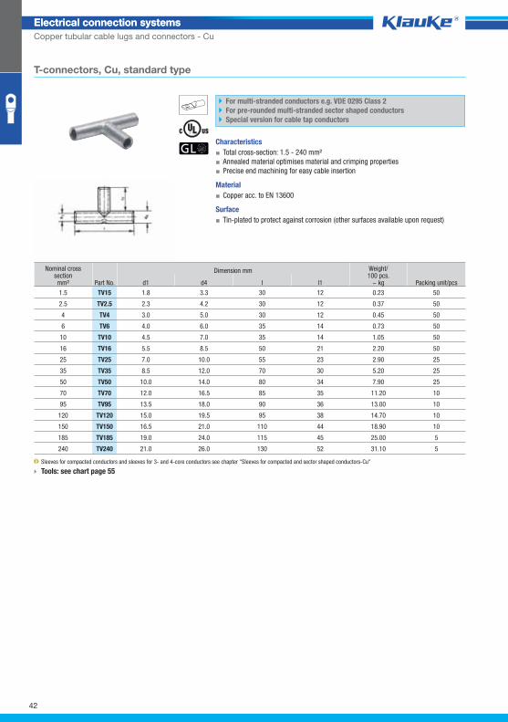
T-connectors, Cu, standard type
For multi-stranded conductors e.g. VDE 0295 Class 2
For pre-rounded multi-stranded sector shaped conductors
Special version for cable tap conductors
Characteristics
▪ Total cross-section: 1.5 - 240 mm²
▪ Annealed material optimises material and crimping properties
▪ Precise end machining for easy cable insertion
Material
▪ Copper acc. to EN 13600
Surface
▪ Tin-plated to protect against corrosion (other surfaces available upon request)
Nominal cross section mm² Part No.
Dimension mm Weight/100 pcs.
~ kg Packing unit/pcs d1 d4 l l1
1.5 TV15 1.8 3.3 30 12 0.23 50
2.5 TV2.5 2.3 4.2 30 12 0.37 50
4 TV4 3.0 5.0 30 12 0.45 50
6 TV6 4.0 6.0 35 14 0.73 50
10 TV10 4.5 7.0 35 14 1.05 50
16 TV16 5.5 8.5 50 21 2.20 50
25 TV25 7.0 10.0 55 23 2.90 25
35 TV35 8.5 12.0 70 30 5.20 25
50 TV50 10.0 14.0 80 34 7.90 25
70 TV70 12.0 16.5 85 35 11.20 10
95 TV95 13.5 18.0 90 36 13.00 10
120 TV120 15.0 19.5 95 38 14.70 10
150 TV150 16.5 21.0 110 44 18.90 10
185 TV185 19.0 24.0 115 45 25.00 5
240 TV240 21.0 26.0 130 52 31.10 5
Sleeves for compacted conductors and sleeves for 3- and 4-core conductors see chapter "Sleeves for compacted and sector shaped conductors-Cu"
Tools: see chart page 55
42
Klauke Hauptkatalog EN_DIN A5.indb 42 07.10.2014 12:16:20
kv15grp
Electrical connection systemsElectrical connection systems
Copper tubular cable lugs and connectors - Cu
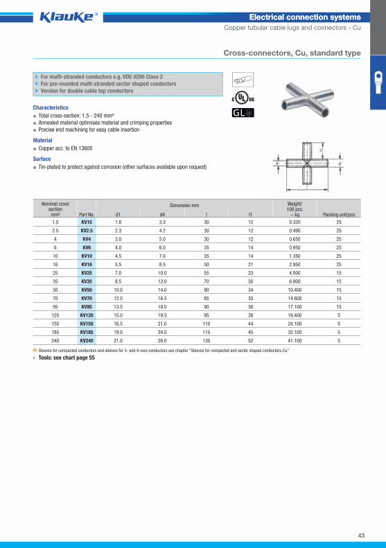
Cross-connectors, Cu, standard type
For multi-stranded conductors e.g. VDE 0295 Class 2
For pre-rounded multi-stranded sector shaped conductors
Version for double cable tap conductors
Characteristics
▪ Total cross-section: 1.5 - 240 mm²
▪ Annealed material optimises material and crimping properties
▪ Precise end machining for easy cable insertion
Material
▪ Copper acc. to EN 13600
Surface
▪ Tin-plated to protect against corrosion (other surfaces available upon request)
Nominal cross section mm² Part No.
Dimension mm Weight/100 pcs.
~ kg Packing unit/pcs d1 d4 l l1
1.5 KV15 1.8 3.3 30 12 0.320 25
2.5 KV2.5 2.3 4.2 30 12 0.490 25
4 KV4 3.0 5.0 30 12 0.650 25
6 KV6 4.0 6.0 35 14 0.950 25
10 KV10 4.5 7.0 35 14 1.350 25
16 KV16 5.5 8.5 50 21 2.950 25
25 KV25 7.0 10.0 55 23 4.000 15
35 KV35 8.5 12.0 70 30 6.900 15
50 KV50 10.0 14.0 80 34 10.400 15
70 KV70 12.0 16.5 85 35 14.600 15
95 KV95 13.5 18.0 90 36 17.100 15
120 KV120 15.0 19.5 95 38 19.400 5
150 KV150 16.5 21.0 110 44 24.100 5
185 KV185 19.0 24.0 115 45 32.100 5
240 KV240 21.0 26.0 130 52 41.100 5
Sleeves for compacted conductors and sleeves for 3- and 4-core conductors see chapter "Sleeves for compacted and sector shaped conductors-Cu"
Tools: see chart page 55
43
Klauke Hauptkatalog EN_DIN A5.indb 43 07.10.2014 12:16:20
602r5grp
Electrical connection systemsElectrical connection systems
Copper tubular cable lugs and connectors - Cu
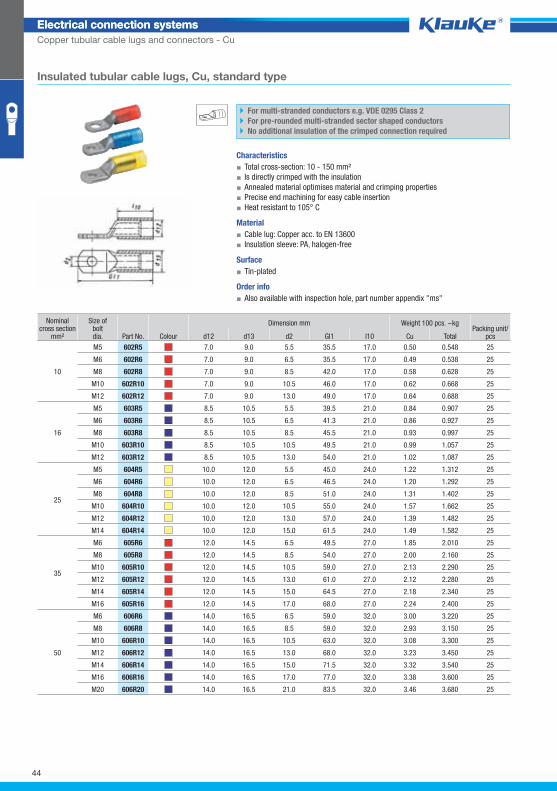
Insulated tubular cable lugs, Cu, standard type
For multi-stranded conductors e.g. VDE 0295 Class 2
For pre-rounded multi-stranded sector shaped conductors
No additional insulation of the crimped connection required
Characteristics
▪ Total cross-section: 10 - 150 mm²
▪ Is directly crimped with the insulation
▪ Annealed material optimises material and crimping properties
▪ Precise end machining for easy cable insertion
▪ Heat resistant to 105° C
Material
▪ Cable lug: Copper acc. to EN 13600
▪ Insulation sleeve: PA, halogen-free
Surface
▪ Tin-plated
Order info
▪ Also available with inspection hole, part number appendix "ms"
Nominal cross section
mm²
Size ofboltdia. Part No. Colour
Dimension mm Weight 100 pcs. ~kg Packing unit/
pcs d12 d13 d2 Gl1 l10 Cu Total
10
M5 602R5 7.0 9.0 5.5 35.5 17.0 0.50 0.548 25
M6 602R6 7.0 9.0 6.5 35.5 17.0 0.49 0.538 25
M8 602R8 7.0 9.0 8.5 42.0 17.0 0.58 0.628 25
M10 602R10 7.0 9.0 10.5 46.0 17.0 0.62 0.668 25
M12 602R12 7.0 9.0 13.0 49.0 17.0 0.64 0.688 25
16
M5 603R5 8.5 10.5 5.5 39.5 21.0 0.84 0.907 25
M6 603R6 8.5 10.5 6.5 41.3 21.0 0.86 0.927 25
M8 603R8 8.5 10.5 8.5 45.5 21.0 0.93 0.997 25
M10 603R10 8.5 10.5 10.5 49.5 21.0 0.99 1.057 25
M12 603R12 8.5 10.5 13.0 54.0 21.0 1.02 1.087 25
25
M5 604R5 10.0 12.0 5.5 45.0 24.0 1.22 1.312 25
M6 604R6 10.0 12.0 6.5 46.5 24.0 1.20 1.292 25
M8 604R8 10.0 12.0 8.5 51.0 24.0 1.31 1.402 25
M10 604R10 10.0 12.0 10.5 55.0 24.0 1.57 1.662 25
M12 604R12 10.0 12.0 13.0 57.0 24.0 1.39 1.482 25
M14 604R14 10.0 12.0 15.0 61.5 24.0 1.49 1.582 25
35
M6 605R6 12.0 14.5 6.5 49.5 27.0 1.85 2.010 25
M8 605R8 12.0 14.5 8.5 54.0 27.0 2.00 2.160 25
M10 605R10 12.0 14.5 10.5 59.0 27.0 2.13 2.290 25
M12 605R12 12.0 14.5 13.0 61.0 27.0 2.12 2.280 25
M14 605R14 12.0 14.5 15.0 64.5 27.0 2.18 2.340 25
M16 605R16 12.0 14.5 17.0 68.0 27.0 2.24 2.400 25
50
M6 606R6 14.0 16.5 6.5 59.0 32.0 3.00 3.220 25
M8 606R8 14.0 16.5 8.5 59.0 32.0 2.93 3.150 25
M10 606R10 14.0 16.5 10.5 63.0 32.0 3.08 3.300 25
M12 606R12 14.0 16.5 13.0 68.0 32.0 3.23 3.450 25
M14 606R14 14.0 16.5 15.0 71.5 32.0 3.32 3.540 25
M16 606R16 14.0 16.5 17.0 77.0 32.0 3.38 3.600 25
M20 606R20 14.0 16.5 21.0 83.5 32.0 3.46 3.680 25
44
Klauke Hauptkatalog EN_DIN A5.indb 44 07.10.2014 12:16:21
Electrical connection systemsElectrical connection systems
Copper tubular cable lugs and connectors - Cu
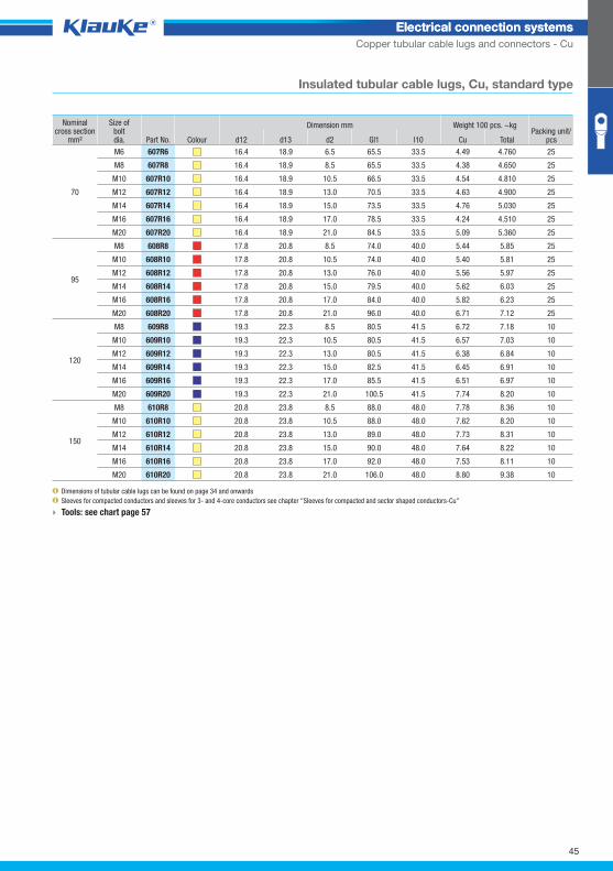
Insulated tubular cable lugs, Cu, standard type
Nominal cross section
mm²
Size ofboltdia. Part No. Colour
Dimension mm Weight 100 pcs. ~kg Packing unit/
pcs d12 d13 d2 Gl1 l10 Cu Total
70
M6 607R6 16.4 18.9 6.5 65.5 33.5 4.49 4.760 25
M8 607R8 16.4 18.9 8.5 65.5 33.5 4.38 4.650 25
M10 607R10 16.4 18.9 10.5 66.5 33.5 4.54 4.810 25
M12 607R12 16.4 18.9 13.0 70.5 33.5 4.63 4.900 25
M14 607R14 16.4 18.9 15.0 73.5 33.5 4.76 5.030 25
M16 607R16 16.4 18.9 17.0 78.5 33.5 4.24 4.510 25
M20 607R20 16.4 18.9 21.0 84.5 33.5 5.09 5.360 25
95
M8 608R8 17.8 20.8 8.5 74.0 40.0 5.44 5.85 25
M10 608R10 17.8 20.8 10.5 74.0 40.0 5.40 5.81 25
M12 608R12 17.8 20.8 13.0 76.0 40.0 5.56 5.97 25
M14 608R14 17.8 20.8 15.0 79.5 40.0 5.62 6.03 25
M16 608R16 17.8 20.8 17.0 84.0 40.0 5.82 6.23 25
M20 608R20 17.8 20.8 21.0 96.0 40.0 6.71 7.12 25
120
M8 609R8 19.3 22.3 8.5 80.5 41.5 6.72 7.18 10
M10 609R10 19.3 22.3 10.5 80.5 41.5 6.57 7.03 10
M12 609R12 19.3 22.3 13.0 80.5 41.5 6.38 6.84 10
M14 609R14 19.3 22.3 15.0 82.5 41.5 6.45 6.91 10
M16 609R16 19.3 22.3 17.0 85.5 41.5 6.51 6.97 10
M20 609R20 19.3 22.3 21.0 100.5 41.5 7.74 8.20 10
150
M8 610R8 20.8 23.8 8.5 88.0 48.0 7.78 8.36 10
M10 610R10 20.8 23.8 10.5 88.0 48.0 7.62 8.20 10
M12 610R12 20.8 23.8 13.0 89.0 48.0 7.73 8.31 10
M14 610R14 20.8 23.8 15.0 90.0 48.0 7.64 8.22 10
M16 610R16 20.8 23.8 17.0 92.0 48.0 7.53 8.11 10
M20 610R20 20.8 23.8 21.0 106.0 48.0 8.80 9.38 10
Dimensions of tubular cable lugs can be found on page 34 and onwards
Sleeves for compacted conductors and sleeves for 3- and 4-core conductors see chapter "Sleeves for compacted and sector shaped conductors-Cu"
Tools: see chart page 57
45
Klauke Hauptkatalog EN_DIN A5.indb 45 07.10.2014 12:16:21
622rgrp
Electrical connection systemsElectrical connection systems
Copper tubular cable lugs and connectors - Cu
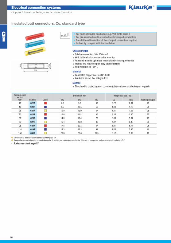
Insulated butt connectors, Cu, standard type
For multi-stranded conductors e.g. VDE 0295 Class 2
For pre-rounded multi-stranded sector shaped conductors
No additional insulation of the crimped connection required
Is directly crimped with the insulation
Characteristics
▪ Total cross-section: 10 - 150 mm²
▪ With buttmarks for precise cable insertion
▪ Annealed material optimises material and crimping properties
▪ Precise end machining for easy cable insertion
▪ Heat resistant to 105° C
Material
▪ Connector: copper acc. to EN 13600
▪ Insulation sleeve: PA, halogen-free
Surface
▪ Tin-plated to protect against corrosion (other surfaces available upon request)
Nominal cross section mm² Part No. Colour
Dimension mm Weight 100 pcs. ~kg
Packing unit/pcs d12 d13 l10 Cu Total
10 622R 7.0 9.0 42 0.72 0.84 25
16 623R 8.5 10.5 50 1.00 1.16 25
25 624R 10.0 12.0 57 1.41 1.63 25
35 625R 12.0 14.4 65 2.24 2.60 25
50 626R 14.0 16.4 72 3.36 3.81 25
70 627R 16.4 19.0 80 4.87 5.46 25
95 628R 17.8 20.8 87 5.91 6.74 25
120 629R 19.3 22.3 94 7.00 7.96 10
150 630R 20.8 23.8 103 8.12 9.32 10
Dimensions of butt connectors can be found on page 40
Sleeves for compacted conductors and sleeves for 3- and 4-core conductors see chapter "Sleeves for compacted and sector shaped conductors-Cu"
Tools: see chart page 57
46
Klauke Hauptkatalog EN_DIN A5.indb 46 07.10.2014 12:16:22
702f5grp
Electrical connection systemsElectrical connection systems
Copper tubular cable lugs and connectors - Cu
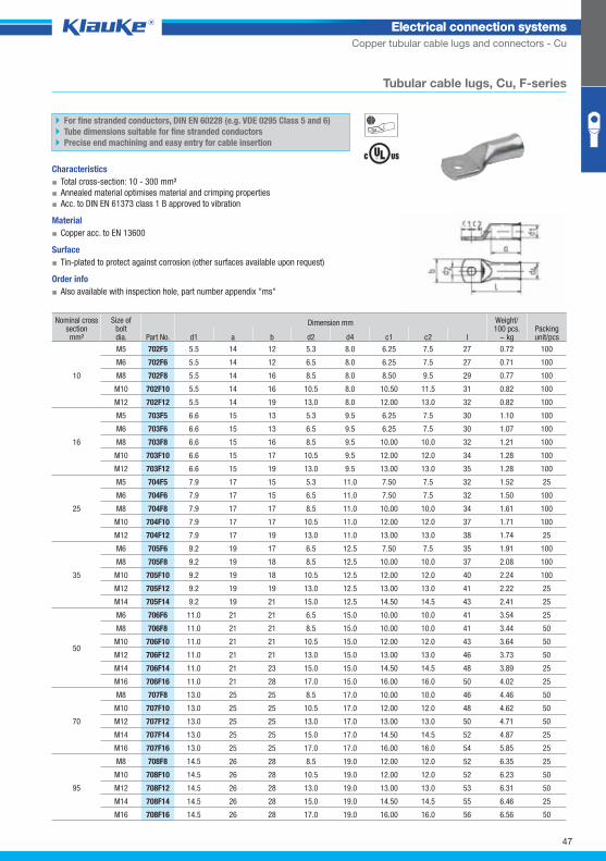
Tubular cable lugs, Cu, F-series
For fine stranded conductors, DIN EN 60228 (e.g. VDE 0295 Class 5 and 6)
Tube dimensions suitable for fine stranded conductors
Precise end machining and easy entry for cable insertion
Characteristics
▪ Total cross-section: 10 - 300 mm²
▪ Annealed material optimises material and crimping properties
▪ Acc. to DIN EN 61373 class 1 B approved to vibration
Material
▪ Copper acc. to EN 13600
Surface
▪ Tin-plated to protect against corrosion (other surfaces available upon request)
Order info
▪ Also available with inspection hole, part number appendix "ms"
Nominal cross section mm²
Size ofbolt dia. Part No.
Dimension mm Weight/100 pcs.
~ kg Packing unit/pcs d1 a b d2 d4 c1 c2 l
10
M5 702F5 5.5 14 12 5.3 8.0 6.25 7.5 27 0.72 100
M6 702F6 5.5 14 12 6.5 8.0 6.25 7.5 27 0.71 100
M8 702F8 5.5 14 16 8.5 8.0 8.50 9.5 29 0.77 100
M10 702F10 5.5 14 16 10.5 8.0 10.50 11.5 31 0.82 100
M12 702F12 5.5 14 19 13.0 8.0 12.00 13.0 32 0.82 100
16
M5 703F5 6.6 15 13 5.3 9.5 6.25 7.5 30 1.10 100
M6 703F6 6.6 15 13 6.5 9.5 6.25 7.5 30 1.07 100
M8 703F8 6.6 15 16 8.5 9.5 10.00 10.0 32 1.21 100
M10 703F10 6.6 15 17 10.5 9.5 12.00 12.0 34 1.28 100
M12 703F12 6.6 15 19 13.0 9.5 13.00 13.0 35 1.28 100
25
M5 704F5 7.9 17 15 5.3 11.0 7.50 7.5 32 1.52 25
M6 704F6 7.9 17 15 6.5 11.0 7.50 7.5 32 1.50 100
M8 704F8 7.9 17 17 8.5 11.0 10.00 10.0 34 1.61 100
M10 704F10 7.9 17 17 10.5 11.0 12.00 12.0 37 1.71 100
M12 704F12 7.9 17 19 13.0 11.0 13.00 13.0 38 1.74 25
35
M6 705F6 9.2 19 17 6.5 12.5 7.50 7.5 35 1.91 100
M8 705F8 9.2 19 18 8.5 12.5 10.00 10.0 37 2.08 100
M10 705F10 9.2 19 18 10.5 12.5 12.00 12.0 40 2.24 100
M12 705F12 9.2 19 19 13.0 12.5 13.00 13.0 41 2.22 25
M14 705F14 9.2 19 21 15.0 12.5 14.50 14.5 43 2.41 25
50
M6 706F6 11.0 21 21 6.5 15.0 10.00 10.0 41 3.54 25
M8 706F8 11.0 21 21 8.5 15.0 10.00 10.0 41 3.44 50
M10 706F10 11.0 21 21 10.5 15.0 12.00 12.0 43 3.64 50
M12 706F12 11.0 21 21 13.0 15.0 13.00 13.0 46 3.73 50
M14 706F14 11.0 21 23 15.0 15.0 14.50 14.5 48 3.89 25
M16 706F16 11.0 21 28 17.0 15.0 16.00 16.0 50 4.02 25
70
M8 707F8 13.0 25 25 8.5 17.0 10.00 10.0 46 4.46 50
M10 707F10 13.0 25 25 10.5 17.0 12.00 12.0 48 4.62 50
M12 707F12 13.0 25 25 13.0 17.0 13.00 13.0 50 4.71 50
M14 707F14 13.0 25 25 15.0 17.0 14.50 14.5 52 4.87 25
M16 707F16 13.0 25 25 17.0 17.0 16.00 16.0 54 5.85 25
95
M8 708F8 14.5 26 28 8.5 19.0 12.00 12.0 52 6.35 25
M10 708F10 14.5 26 28 10.5 19.0 12.00 12.0 52 6.23 50
M12 708F12 14.5 26 28 13.0 19.0 13.00 13.0 53 6.31 50
M14 708F14 14.5 26 28 15.0 19.0 14.50 14.5 55 6.46 25
M16 708F16 14.5 26 28 17.0 19.0 16.00 16.0 56 6.56 50
47
Klauke Hauptkatalog EN_DIN A5.indb 47 07.10.2014 12:16:22
Electrical connection systemsElectrical connection systems
Copper tubular cable lugs and connectors - Cu
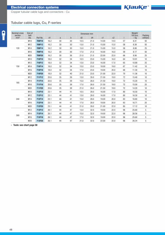
Tubular cable lugs, Cu, F-series
Nominal cross section mm²
Size ofbolt dia. Part No.
Dimension mm Weight/100 pcs.
~ kg Packing unit/pcs d1 a b d2 d4 c1 c2 l
120
M10 709F10 16.2 30 30 10.5 21.0 14.00 14.0 57 8.31 50
M12 709F12 16.2 30 30 13.0 21.0 15.00 15.0 58 8.39 50
M14 709F14 16.2 30 30 15.0 21.0 15.00 15.0 58 8.06 25
M16 709F16 16.2 30 30 17.0 21.0 16.00 16.0 59 8.17 50
M20 709F20 16.2 30 36 21.0 21.0 22.00 22.0 66 9.56 25
150
M10 710F10 18.0 32 34 10.5 23.0 15.00 16.0 64 10.91 10
M12 710F12 18.0 32 34 13.0 23.0 16.00 17.0 65 10.89 25
M14 710F14 18.0 32 34 15.0 23.0 18.00 19.0 67 11.42 10
M16 710F16 18.0 32 34 17.0 23.0 19.00 20.0 68 11.30 10
M20 710F20 18.0 32 40 21.0 23.0 21.00 22.0 70 11.36 10
185
M12 711F12 20.6 35 39 13.0 26.0 21.50 19.0 72 15.40 10
M14 711F14 20.6 35 39 15.0 26.0 21.50 19.0 72 15.20 10
M16 711F16 20.6 35 39 17.0 26.0 21.50 19.0 72 15.00 25
M20 711F20 20.6 35 39 21.0 26.0 21.50 19.0 72 14.20 10
240
M10 712F10 23.1 44 41 10.5 28.0 16.00 17.0 80 16.50 10
M12 712F12 23.1 44 41 13.0 28.0 16.00 17.0 80 16.30 10
M14 712F14 23.1 44 41 15.0 28.0 19.00 20.0 83 16.80 10
M16 712F16 23.1 44 41 17.0 28.0 19.00 20.0 83 16.71 25
M20 712F20 23.1 44 41 21.0 28.0 21.00 22.0 85 17.12 10
300
M12 713F12 26.1 44 47 13.0 32.0 19.00 22.0 96 25.60 5
M14 713F14 26.1 44 47 15.0 32.0 19.00 22.0 96 26.56 5
M16 713F16 26.1 44 47 17.0 32.0 19.00 22.0 96 25.60 5
M20 713F20 26.1 44 47 21.0 32.0 22.00 22.0 96 26.24 5
Tools: see chart page 58
48
Klauke Hauptkatalog EN_DIN A5.indb 48 07.10.2014 12:16:23
742f5grp
Electrical connection systemsElectrical connection systems
Copper tubular cable lugs and connectors - Cu
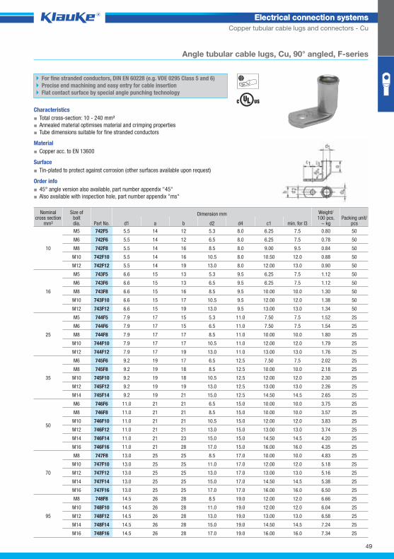
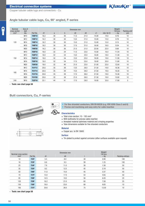
Angle tubular cable lugs, Cu, 90° angled, F-series
For fine stranded conductors, DIN EN 60228 (e.g. VDE 0295 Class 5 and 6)
Precise end machining and easy entry for cable insertion
Flat contact surface by special angle punching technology
Characteristics
▪ Total cross-section: 10 - 240 mm²
▪ Annealed material optimises material and crimping properties
▪ Tube dimensions suitable for fine stranded conductors
Material
▪ Copper acc. to EN 13600
Surface
▪ Tin-plated to protect against corrosion (other surfaces available upon request)
Order info
▪ 45° angle version also available, part number appendix "45"
▪ Also available with inspection hole, part number appendix "ms"
Nominal cross section
mm²
Size ofbolt dia. Part No.
Dimension mm Weight/100 pcs.
~ kg Packing unit/
pcs d1 a b d2 d4 c1 min. for l3
10
M5 742F5 5.5 14 12 5.3 8.0 6.25 7.5 0.80 50
M6 742F6 5.5 14 12 6.5 8.0 6.25 7.5 0.78 50
M8 742F8 5.5 14 16 8.5 8.0 9.00 9.5 0.84 50
M10 742F10 5.5 14 16 10.5 8.0 10.50 12.0 0.88 50
M12 742F12 5.5 14 19 13.0 8.0 12.00 13.0 0.90 50
16
M5 743F5 6.6 15 13 5.3 9.5 6.25 7.5 1.12 50
M6 743F6 6.6 15 13 6.5 9.5 6.25 7.5 1.12 50
M8 743F8 6.6 15 16 8.5 9.5 10.00 10.0 1.30 50
M10 743F10 6.6 15 17 10.5 9.5 12.00 12.0 1.38 50
M12 743F12 6.6 15 19 13.0 9.5 13.00 13.0 1.34 50
25
M5 744F5 7.9 17 15 5.3 11.0 7.50 7.5 1.52 25
M6 744F6 7.9 17 15 6.5 11.0 7.50 7.5 1.54 25
M8 744F8 7.9 17 17 8.5 11.0 10.00 10.0 1.80 25
M10 744F10 7.9 17 17 10.5 11.0 12.00 12.0 1.79 25
M12 744F12 7.9 17 19 13.0 11.0 13.00 13.0 1.76 25
35
M6 745F6 9.2 19 17 6.5 12.5 7.50 7.5 2.02 25
M8 745F8 9.2 19 18 8.5 12.5 10.00 10.0 2.18 25
M10 745F10 9.2 19 18 10.5 12.5 12.00 12.0 2.30 25
M12 745F12 9.2 19 19 13.0 12.5 13.00 13.0 2.26 25
M14 745F14 9.2 19 21 15.0 12.5 14.50 14.5 2.65 25
50
M6 746F6 11.0 21 21 6.5 15.0 10.00 10.0 3.75 25
M8 746F8 11.0 21 21 8.5 15.0 10.00 10.0 3.57 25
M10 746F10 11.0 21 21 10.5 15.0 12.00 12.0 3.83 25
M12 746F12 11.0 21 21 13.0 15.0 13.00 13.0 3.74 25
M14 746F14 11.0 21 23 15.0 15.0 14.50 14.5 4.20 25
M16 746F16 11.0 21 28 17.0 15.0 16.00 16.0 4.35 25
70
M8 747F8 13.0 25 25 8.5 17.0 10.00 10.0 4.83 25
M10 747F10 13.0 25 25 11.0 17.0 12.00 12.0 5.18 25
M12 747F12 13.0 25 25 13.0 17.0 13.00 13.0 5.16 25
M14 747F14 13.0 25 25 15.0 17.0 14.50 14.5 5.38 25
M16 747F16 13.0 25 25 17.0 17.0 16.00 16.0 6.50 25
95
M8 748F8 14.5 26 28 8.5 19.0 12.00 12.0 6.66 25
M10 748F10 14.5 26 28 11.0 19.0 12.00 12.0 6.04 25
M12 748F12 14.5 26 28 13.0 19.0 13.00 13.0 6.58 25
M14 748F14 14.5 26 28 15.0 19.0 14.50 14.5 7.24 25
M16 748F16 14.5 26 28 17.0 19.0 16.00 16.0 7.34 25
49
Klauke Hauptkatalog EN_DIN A5.indb 49 07.10.2014 12:16:23
722fgrp
Electrical connection systemsElectrical connection systems
Copper tubular cable lugs and connectors - Cu
Angle tubular cable lugs, Cu, 90° angled, F-series
Nominal cross section
mm²
Size ofbolt dia. Part No.
Dimension mm Weight/100 pcs.
~ kg Packing unit/
pcs d1 a b d2 d4 c1 min. for l3
120
M10 749F10 16.2 30 30 11.0 21.0 14.00 14.0 8.76 10
M12 749F12 16.2 30 30 13.0 21.0 15.00 15.0 8.76 10
M14 749F14 16.2 30 30 15.0 21.0 15.00 15.0 9.15 10
M16 749F16 16.2 30 30 17.0 21.0 16.00 16.0 8.54 10
M20 749F20 16.2 30 36 21.0 21.0 22.00 22.0 9.60 10
150
M10 750F10 18.0 32 34 11.0 23.0 15.00 16.0 11.54 10
M12 750F12 18.0 32 34 13.0 23.0 16.00 18.0 11.58 10
M14 750F14 18.0 32 34 15.0 23.0 18.00 19.0 11.90 10
M16 750F16 18.0 32 34 17.0 23.0 19.00 20.0 11.80 10
M20 750F20 18.0 32 40 21.0 23.0 21.00 22.0 12.00 10
185
M12 751F12 20.6 35 39 13.0 26.0 21.50 19.0 16.36 10
M14 751F14 20.6 35 39 15.0 26.0 21.50 19.0 16.20 10
M16 751F16 20.6 35 39 17.0 26.0 21.50 19.0 15.36 10
M20 751F20 20.6 35 39 21.0 26.0 21.50 19.0 15.80 10
240 M16 752F16 23.1 44 41 17.0 28.0 19.00 20.0 17.80 5
Tools: see chart page 58
Butt connectors, Cu, F-series
For fine stranded conductors, DIN EN 60228 (e.g. VDE 0295 Class 5 and 6)
Precise end machining and easy entry for cable insertion
Characteristics
▪ Total cross-section: 10 - 185 mm²
▪ With buttmarks for precise cable insertion
▪ Annealed material optimises material and crimping properties
▪ Tube dimensions suitable for fine stranded conductors
Material
▪ Copper acc. to EN 13600
Surface
▪ Tin-plated to protect against corrosion (other surfaces available upon request)
Nominal cross section mm² Part No.
Dimension mm Weight/100 pcs.
~ kg Packing unit/pcs d1 d4 l
10 722F 5.5 8.0 38 0.90 100
16 723F 6.6 9.5 38 1.25 100
25 724F 7.9 11.0 38 1.56 50
35 725F 9.2 12.5 45 2.19 50
50 726F 11.0 15.0 45 3.37 50
70 727F 13.0 17.0 54 4.65 50
95 728F 14.5 19.0 56 6.05 25
120 729F 16.2 21.0 60 7.58 25
150 730F 18.0 23.0 68 9.83 10
185 731F 20.6 26.0 75 13.30 10
Tools: see chart page 58
50
Klauke Hauptkatalog EN_DIN A5.indb 50 07.10.2014 12:16:23
sr65grp
Electrical connection systemsElectrical connection systems
Copper tubular cable lugs and connectors - Cu
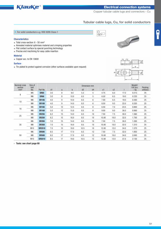
Tubular cable lugs, Cu, for solid conductors
For solid conductors e.g. VDE 0295 Class 1
Characteristics
▪ Total cross-section: 6 - 50 mm²
▪ Annealed material optimises material and crimping properties
▪ Flat contact surface by special punching technology
▪ Precise end machining for easy cable insertion
Material
▪ Copper acc. to EN 13600
Surface
▪ Tin-plated to protect against corrosion (other surfaces available upon request)
Nominal cross section mm²
Size ofboltdia. Part No.
Dimension mm Weight/100 pcs.
~ kg Packing unit/pcs d1 a b d2 d4 c1 c2 l
6 M5 SR65 3.0 8 9.0 5.3 5 4.75 6.0 17.0 0.213 25
M6 SR66 3.0 8 10.0 6.5 5 6.50 6.5 19.0 0.220 25
10 M6 SR106 4.0 9 10.0 6.5 6 7.00 6.5 19.0 0.300 25
M8 SR108 4.0 9 14.0 8.5 6 8.50 9.5 22.0 0.320 25
16 M6 SR166 5.0 12 12.5 6.5 8 6.50 7.0 23.5 0.800 25
M8 SR168 5.0 12 15.0 8.5 8 9.00 9.0 26.0 0.900 25
25 M6 SR256 6.2 15 14.0 6.5 10 7.50 7.5 30.0 1.560 25
M8 SR258 6.2 15 16.0 8.5 10 10.00 10.0 32.0 1.700 25
35
M6 SR356 7.0 15 14.0 6.5 10 7.50 7.5 30.0 1.200 25
M8 SR358 7.0 15 16.0 8.5 10 10.00 10.0 32.0 1.310 25
M10 SR3510 7.0 15 18.0 10.5 10 12.00 12.0 34.0 1.570 25
50
M6 SR506 8.5 17 17.0 6.5 12 7.50 7.5 32.0 1.850 25
M8 SR508 8.5 17 17.0 8.5 12 10.00 10.0 34.0 2.000 25
M10 SR5010 8.5 17 19.0 10.5 12 12.00 12.0 37.0 2.130 25
Tools: see chart page 60
51
Klauke Hauptkatalog EN_DIN A5.indb 51 07.10.2014 12:16:24
sv1525grp
stv1525grp
Electrical connection systemsElectrical connection systems
Copper tubular cable lugs and connectors - Cu
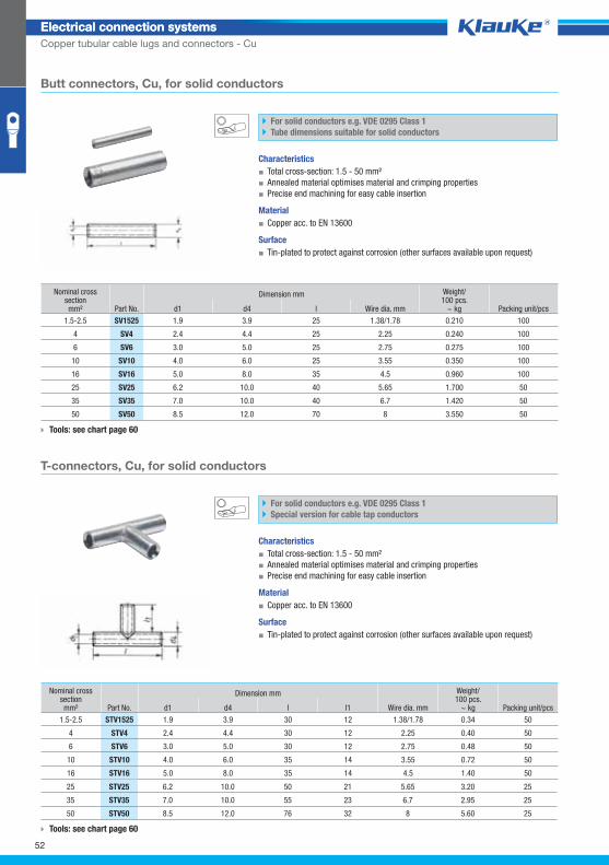
Butt connectors, Cu, for solid conductors
For solid conductors e.g. VDE 0295 Class 1
Tube dimensions suitable for solid conductors
Characteristics
▪ Total cross-section: 1.5 - 50 mm²
▪ Annealed material optimises material and crimping properties
▪ Precise end machining for easy cable insertion
Material
▪ Copper acc. to EN 13600
Surface
▪ Tin-plated to protect against corrosion (other surfaces available upon request)
Nominal cross section mm² Part No.
Dimension mm Weight/100 pcs.
~ kg Packing unit/pcs d1 d4 l Wire dia. mm
1.5-2.5 SV1525 1.9 3.9 25 1.38/1.78 0.210 100
4 SV4 2.4 4.4 25 2.25 0.240 100
6 SV6 3.0 5.0 25 2.75 0.275 100
10 SV10 4.0 6.0 25 3.55 0.350 100
16 SV16 5.0 8.0 35 4.5 0.960 100
25 SV25 6.2 10.0 40 5.65 1.700 50
35 SV35 7.0 10.0 40 6.7 1.420 50
50 SV50 8.5 12.0 70 8 3.550 50
Tools: see chart page 60
T-connectors, Cu, for solid conductors
For solid conductors e.g. VDE 0295 Class 1
Special version for cable tap conductors
Characteristics
▪ Total cross-section: 1.5 - 50 mm²
▪ Annealed material optimises material and crimping properties
▪ Precise end machining for easy cable insertion
Material
▪ Copper acc. to EN 13600
Surface
▪ Tin-plated to protect against corrosion (other surfaces available upon request)
Nominal cross section mm² Part No.
Dimension mm
Wire dia. mm
Weight/100 pcs.
~ kg Packing unit/pcs d1 d4 l l1
1.5-2.5 STV1525 1.9 3.9 30 12 1.38/1.78 0.34 50
4 STV4 2.4 4.4 30 12 2.25 0.40 50
6 STV6 3.0 5.0 30 12 2.75 0.48 50
10 STV10 4.0 6.0 35 14 3.55 0.72 50
16 STV16 5.0 8.0 35 14 4.5 1.40 50
25 STV25 6.2 10.0 50 21 5.65 3.20 25
35 STV35 7.0 10.0 55 23 6.7 2.95 25
50 STV50 8.5 12.0 76 32 8 5.60 25
Tools: see chart page 60
52
Klauke Hauptkatalog EN_DIN A5.indb 52 07.10.2014 12:16:24
skv1525grp
Electrical connection systemsElectrical connection systems
Copper tubular cable lugs and connectors - Cu
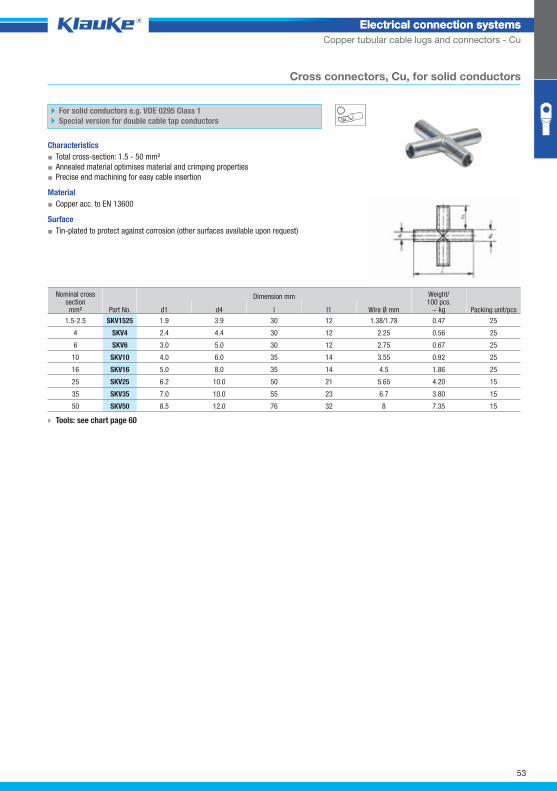
Cross connectors, Cu, for solid conductors
For solid conductors e.g. VDE 0295 Class 1
Special version for double cable tap conductors
Characteristics
▪ Total cross-section: 1.5 - 50 mm²
▪ Annealed material optimises material and crimping properties
▪ Precise end machining for easy cable insertion
Material
▪ Copper acc. to EN 13600
Surface
▪ Tin-plated to protect against corrosion (other surfaces available upon request)
Nominal cross section mm² Part No.
Dimension mm Weight/100 pcs.
~ kg Packing unit/pcs d1 d4 l l1 Wire Ø mm
1.5-2.5 SKV1525 1.9 3.9 30 12 1.38/1.78 0.47 25
4 SKV4 2.4 4.4 30 12 2.25 0.56 25
6 SKV6 3.0 5.0 30 12 2.75 0.67 25
10 SKV10 4.0 6.0 35 14 3.55 0.92 25
16 SKV16 5.0 8.0 35 14 4.5 1.86 25
25 SKV25 6.2 10.0 50 21 5.65 4.20 15
35 SKV35 7.0 10.0 55 23 6.7 3.80 15
50 SKV50 8.5 12.0 76 32 8 7.35 15
Tools: see chart page 60
53
Klauke Hauptkatalog EN_DIN A5.indb 53 07.10.2014 12:16:25
5sg6grp
Electrical connection systemsElectrical connection systems
Copper tubular cable lugs and connectors - Cu
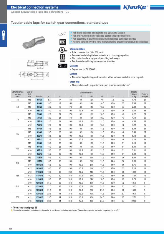
Tubular cable lugs for switch gear connections, standard type
For multi-stranded conductors e.g. VDE 0295 Class 2
For pre-rounded multi-stranded sector shaped conductors
For assembly in switch cabinets with reduced connecting space
Narrow version owed to new manufacturing processes without material loss
Characteristics
▪ Total cross-section: 35 - 300 mm²
▪ Annealed material optimises material and crimping properties
▪ Flat contact surface by special punching technology
▪ Precise end machining for easy cable insertion
Material
▪ Copper acc. to EN 13600
Surface
▪ Tin-plated to protect against corrosion (other surfaces available upon request)
Order info
▪ Also available with inspection hole, part number appendix "ms"
Nominal cross section mm²
Size ofboltdia. Part No.
Dimension mm Weight/100 pcs.
~ kg Packing unit/pcs d1 a b d2 d4 c1 c2 l
35 M6 5SG6 8.5 17 15.0 6.5 12.0 7.5 7.5 32 1.78 25
50
M6 6SG6 10.0 19 15.0 6.5 14.0 10.0 10.0 37 2.95 25
M8 6SG8 10.0 19 17.0 8.5 14.0 10.0 10.0 37 2.82 25
M10 6SG10 10.0 19 19.0 10.5 14.0 11.5 12.0 39 3.08 25
70
M6 7SG6 12.0 21 17.0 6.5 16.5 10.0 10.0 43 4.22 25
M8 7SG8 12.0 21 17.0 8.5 16.5 10.0 10.0 43 4.10 25
M10 7SG10 12.0 21 19.0 10.5 16.5 11.5 12.0 44 4.45 25
M12 7SG12 12.0 21 19.0 13.0 16.5 13.0 13.0 46 4.22 25
95
M6 8SG6 13.5 25 19.0 6.5 18.0 11.5 12.0 48 5.49 25
M8 8SG8 13.5 25 19.0 8.5 18.0 11.5 12.0 48 5.46 25
M10 8SG10 13.5 25 19.0 10.5 18.0 11.5 12.0 48 5.13 25
M12 8SG12 13.5 25 19.0 13.0 18.0 13.0 13.0 49 5.15 25
120
M6 9SG6 15.0 26 19.0 6.5 19.5 11.5 14.0 51 6.16 10
M8 9SG8 15.0 26 19.0 8.5 19.5 11.5 14.0 51 5.94 10
M10 9SG10 15.0 26 19.0 10.5 19.5 11.5 14.0 51 5.81 10
M12 9SG12 15.0 26 19.0 13.0 19.5 14.0 14.0 51 5.92 10
150
M6 10SG6 16.5 30 19.0 6.5 21.0 11.5 14.0 56 6.85 10
M8 10SG8 16.5 30 19.0 8.5 21.0 11.5 14.0 56 6.80 10
M10 10SG10 16.5 30 19.0 10.5 21.0 11.5 14.0 56 6.75 10
M12 10SG12 16.5 30 19.0 13.0 21.0 15.0 15.0 57 7.15 10
185
M10 11SG10 19.0 30 24.5 10.5 24.0 11.5 18.0 65 10.59 10
M12 11SG12 19.0 30 31.0 13.0 24.0 18.0 18.0 65 11.09 10
M16 11SG16 19.0 30 31.0 17.0 24.0 18.0 18.0 65 9.76 10
240
M10 12SG10 21.0 35 31.0 10.5 26.0 11.5 19.0 72 12.70 5
M12 12SG12 21.0 35 31.0 13.0 26.0 21.5 19.0 72 13.72 5
M16 12SG16 21.0 35 31.0 17.0 26.0 21.5 19.0 72 13.28 5
300
M10 13SG10 23.5 44 31.0 10.5 30.0 11.5 24.0 87 19.70 5
M12 13SG12 23.5 44 31.0 13.0 30.0 24.0 24.0 87 22.72 5
M16 13SG16 23.5 44 31.0 17.0 30.0 24.0 24.0 87 22.50 5
Tools: see chart page 55 Sleeves for compacted conductors and sleeves for 3- and 4-core conductors see chapter "Sleeves for compacted and sector shaped conductors-Cu"
54
Klauke Hauptkatalog EN_DIN A5.indb 54 07.10.2014 12:16:25
Electrical connection systemsElectrical connection systems
Copper tubular cable lugs and connectors - Cu
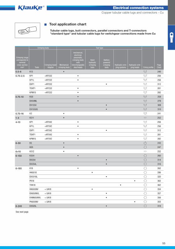
^WZT_RKS_normal^ � Tool application chart
Tubular cable lugs, butt connectors, parallel connectors and T-connectors "standard type" and tubular cable lugs for switchgear connections made from Cu
Crimping tools Tool type
Crimping rangecorresponds to
nominalcross-section
mm² ToolsCrimping head/
AdapterMechanical
crimping tools
mechanical,electrical,
pneumatic, crimping tools
with interchangeable
dies/heads
Handhydraulic crimping
tools
Batterypowered crimping
toolsHydraulic crim-ping systems
Hydraulic crim-ping heads Crimp profile
Page(Tool)
See next page
0.5-6
KP1 +KP232 • 256
KP1L +KP232 • 256
EKP1 +KP232 • 312
TEKP1 +KP232 • 281
KPM15 +KP232 • 282
0.75-2.5
K50 • 259
EK50ML • 278
EK1550 • 308
EK1550G • 310
0.75-10
K2 • 2410.75-16
K511 • 2521-4
KP1 +KP242 • 256
KP1L +KP242 • 256
EKP1 +KP242 • 312
TEKP1 +KP242 • 281
KPM15 +KP242 • 282
4-10
K5 • 243
K05 • 247
6-50
K512 • 2526+10
K354 • 260
EK354 • 314
EK354L • 316
6-150
K18 • 262
HK6018 • 286
EK5018L • 320
PK18 • 362
THK18 • 362
HK60UNV + UA18 • 354
EK60UNVL + UA18 • 357
EKM60UNVL + UA18 • 356
PK60UNV + UA18 • 355
6-185
EK505L • 3186-240
K13 • 2400.5-6
55
Klauke Hauptkatalog EN_DIN A5.indb 55 07.10.2014 12:16:26
Electrical connection systemsElectrical connection systems
Copper tubular cable lugs and connectors - Cu
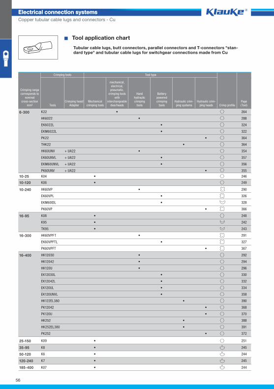
� Tool application chart
Tubular cable lugs, butt connectors, parallel connectors and T-connectors "stan-dard type" and tubular cable lugs for switchgear connections made from Cu
Crimping tools Tool type
Crimping rangecorresponds to
nominalcross-section
mm² ToolsCrimping head/
AdapterMechanical
crimping tools
mechanical,electrical,
pneumatic, crimping tools
with interchangeable
dies/heads
Handhydraulic crimping
tools
Batterypowered crimping
toolsHydraulic crim-ping systems
Hydraulic crim-ping heads Crimp profile
Page(Tool)
K22 • 264
HK6022 • 288
EK6022L • 324
EKM6022L • 322
PK22 • 364
THK22 • 364
HK60UNV + UA22 • 354
EK60UNVL + UA22 • 357
EKM60UNVL + UA22 • 356
PK60UNV + UA22 • 355
6-300
HK60VP • 290
EK60VPL • 326
EKM60IDL • 328
PK60VP • 366
10-240
K08 • 248
K95 • 242
TK95 • 243
16-95
HK60VPFT • 291
EK60VPFTL • 327
PK60VPFT • 367
16-300
HK12030 • 292
HK12042 • 294
HK120U • 296
EK12030L • 330
EK12042L • 332
EK120UL • 334
EK120UNVL • 358
HK122EL380 • 390
PK12042 • 368
PK120U • 370
HK252 • 388
HK252EL380 • 391
PK252 • 372
16-400
K09 • 25125-150
K6 • 24450-120
K07 • 244185-400
K04 • 24610-25
K06 • 24910-120
K8 • 24535-95
K7 • 245120-240
56
Klauke Hauptkatalog EN_DIN A5.indb 56 07.10.2014 12:16:26
Electrical connection systemsElectrical connection systems
Copper tubular cable lugs and connectors - Cu
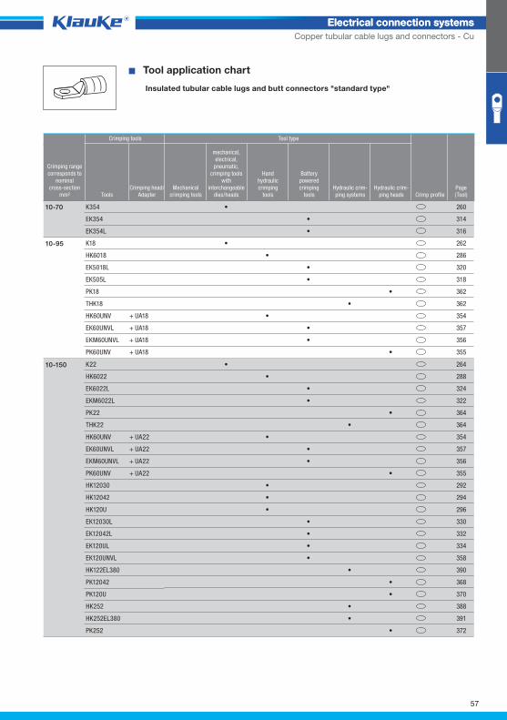
^WZT_RKS_isoliert^ � Tool application chart
Insulated tubular cable lugs and butt connectors "standard type"
Crimping tools Tool type
Crimping rangecorresponds to
nominalcross-section
mm² ToolsCrimping head/
AdapterMechanical
crimping tools
mechanical,electrical,
pneumatic, crimping tools
with interchangeable
dies/heads
Handhydraulic crimping
tools
Batterypowered crimping
toolsHydraulic crim-ping systems
Hydraulic crim-ping heads Crimp profile
Page(Tool)
K354 • 260
EK354 • 314
EK354L • 316
10-70
K18 • 262
HK6018 • 286
EK5018L • 320
EK505L • 318
PK18 • 362
THK18 • 362
HK60UNV + UA18 • 354
EK60UNVL + UA18 • 357
EKM60UNVL + UA18 • 356
PK60UNV + UA18 • 355
10-95
K22 • 264
HK6022 • 288
EK6022L • 324
EKM6022L • 322
PK22 • 364
THK22 • 364
HK60UNV + UA22 • 354
EK60UNVL + UA22 • 357
EKM60UNVL + UA22 • 356
PK60UNV + UA22 • 355
HK12030 • 292
HK12042 • 294
HK120U • 296
EK12030L • 330
EK12042L • 332
EK120UL • 334
EK120UNVL • 358
HK122EL380 • 390
PK12042 • 368
PK120U • 370
HK252 • 388
HK252EL380 • 391
PK252 • 372
10-150
57
Klauke Hauptkatalog EN_DIN A5.indb 57 07.10.2014 12:16:26
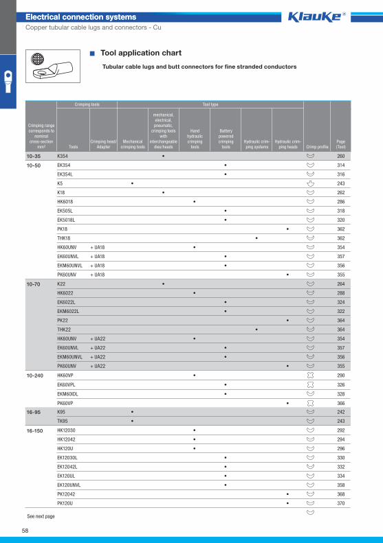
Electrical connection systemsElectrical connection systems
Copper tubular cable lugs and connectors - Cu
^WZT_RKS_feindrähtig^ � Tool application chart
Tubular cable lugs and butt connectors for fine stranded conductors
Crimping tools Tool type
Crimping rangecorresponds to
nominalcross-section
mm² ToolsCrimping head/
AdapterMechanical
crimping tools
mechanical,electrical,
pneumatic, crimping tools
with interchangeable
dies/heads
Handhydraulic crimping
tools
Batterypowered crimping
toolsHydraulic crim-ping systems
Hydraulic crim-ping heads Crimp profile
Page(Tool)
K354 • 26010-35
EK354 • 314
EK354L • 316
K5 • 243
K18 • 262
HK6018 • 286
EK505L • 318
EK5018L • 320
PK18 • 362
THK18 • 362
HK60UNV + UA18 • 354
EK60UNVL + UA18 • 357
EKM60UNVL + UA18 • 356
PK60UNV + UA18 • 355
10-50
K22 • 264
HK6022 • 288
EK6022L • 324
EKM6022L • 322
PK22 • 364
THK22 • 364
HK60UNV + UA22 • 354
EK60UNVL + UA22 • 357
EKM60UNVL + UA22 • 356
PK60UNV + UA22 • 355
10-70
HK60VP • 290
EK60VPL • 326
EKM60IDL • 328
PK60VP • 366
10-240
K95 • 242
TK95 • 243
16-95
HK12030 • 292
HK12042 • 294
HK120U • 296
EK12030L • 330
EK12042L • 332
EK120UL • 334
EK120UNVL • 358
PK12042 • 368
PK120U • 370
16-150
See next page
58
Klauke Hauptkatalog EN_DIN A5.indb 58 07.10.2014 12:16:27
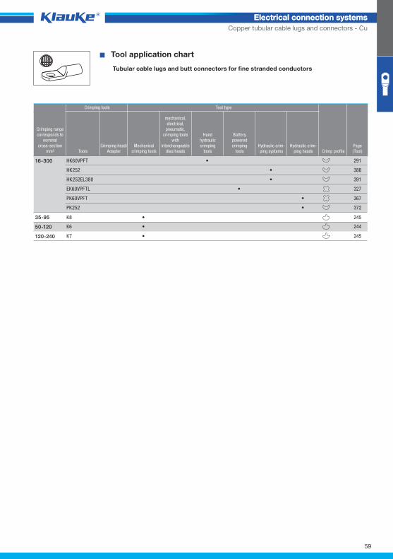
Electrical connection systemsElectrical connection systems
Copper tubular cable lugs and connectors - Cu
� Tool application chart
Tubular cable lugs and butt connectors for fine stranded conductors
Crimping tools Tool type
Crimping rangecorresponds to
nominalcross-section
mm² ToolsCrimping head/
AdapterMechanical
crimping tools
mechanical,electrical,
pneumatic, crimping tools
with interchangeable
dies/heads
Handhydraulic crimping
tools
Batterypowered crimping
toolsHydraulic crim-ping systems
Hydraulic crim-ping heads Crimp profile
Page(Tool)
HK60VPFT • 291
HK252 • 388
HK252EL380 • 391
EK60VPFTL • 327
PK60VPFT • 367
PK252 • 372
16-300
K6 • 24450-120
K7 • 245120-240
K8 • 24535-95
59
Klauke Hauptkatalog EN_DIN A5.indb 59 07.10.2014 12:16:27
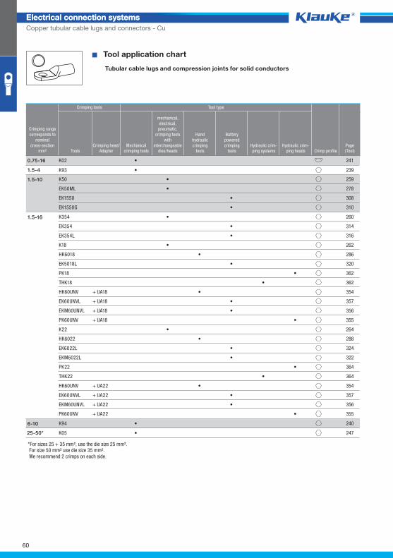
Electrical connection systemsElectrical connection systems
Copper tubular cable lugs and connectors - Cu
^WZT_RKS_massiv^ � Tool application chart
Tubular cable lugs and compression joints for solid conductors
Crimping tools Tool type
Crimping rangecorresponds to
nominalcross-section
mm² ToolsCrimping head/
AdapterMechanical
crimping tools
mechanical,electrical,
pneumatic, crimping tools
with interchangeable
dies/heads
Handhydraulic crimping
tools
Batterypowered crimping
toolsHydraulic crim-ping systems
Hydraulic crim-ping heads Crimp profile
Page(Tool)
K02 • 2410.75-16
K50 • 259
EK50ML • 278
EK1550 • 308
EK1550G • 310
1.5-10
K354 • 260
EK354 • 314
EK354L • 316
K18 • 262
HK6018 • 286
EK5018L • 320
PK18 • 362
THK18 • 362
HK60UNV + UA18 • 354
EK60UNVL + UA18 • 357
EKM60UNVL + UA18 • 356
PK60UNV + UA18 • 355
K22 • 264
HK6022 • 288
EK6022L • 324
EKM6022L • 322
PK22 • 364
THK22 • 364
1.5-16
HK60UNV + UA22 • 354
EK60UNVL + UA22 • 357
EKM60UNVL + UA22 • 356
PK60UNV + UA22 • 355
K94 • 240
25-50* K05 • 247
6-10
*For sizes 25 + 35 mm², use the die size 25 mm². For size 50 mm² use die size 35 mm². We recommend 2 crimps on each side.
K93 • 2391.5-4
60
Klauke Hauptkatalog EN_DIN A5.indb 60 07.10.2014 12:16:27
Electrical connection systemsElectrical connection systems
Copper tubular cable lugs and connectors - Cu
61
Klauke Hauptkatalog EN_DIN A5.indb 61 07.10.2014 12:16:27
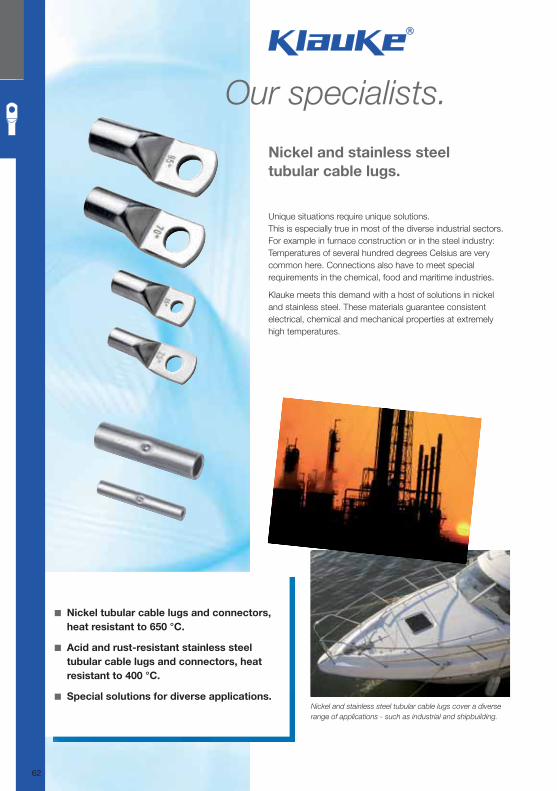
Nickel and stainless steel
tubular cable lugs.
◾ Nickel tubular cable lugs and connectors,
heat resistant to 650 °C.
◾ Acid and rust-resistant stainless steel
tubular cable lugs and connectors, heat
resistant to 400 °C.
◾ Special solutions for diverse applications.Nickel and stainless steel tubular cable lugs cover a diverse
range of applications - such as industrial and shipbuilding.
Our specialists.
Unique situations require unique solutions.
This is especially true in most of the diverse industrial sectors.
For example in furnace construction or in the steel industry:
Temperatures of several hundred degrees Celsius are very
common here. Connections also have to meet special
requirements in the chemical, food and maritime industries.
Klauke meets this demand with a host of solutions in nickel
and stainless steel. These materials guarantee consistent
electrical, chemical and mechanical properties at extremely
high temperatures.
62
Klauke Hauptkatalog EN_DIN A5.indb 62 07.10.2014 12:16:28
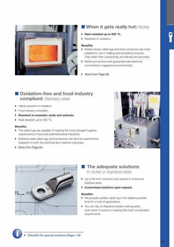
■ When it gets really hot: Nickel.
▸ Heat resistant up to 650 °C.
▸ Resistant to oxidation.
Benefi ts:
▸ Nickel tubular cable lugs and butt connectors are most
suitable for use in heating and annealing furnaces.
They retain their conductivity and failures are excluded.
▸ Nickel connectors even guarantee safe electrical
connections in aggressive environments.
■ Oxidation-free and food-industry compliant: Stainless steel.
▸ Highly resistant to oxidation.
▸ Food industry-compliant.
▸ Resistant to seawater, acids and solvents.
▸ Heat resistant up to 400 °C.
Benefi ts:
▸ The cable lugs are capable of meeting the most stringent hygiene
requirements in food and pharmaceutical industries.
▸ Stainless steel cable lugs and connectors can also be used without
hesitation in both the chemical and maritime industries.
■ The adequate solutions
in nickel or stainless steel.
▸ Up to 95 mm2 nominal cross section in nickel and
stainless steel.
▸ Customised solutions upon request.
Benefi ts:
▸ We provide suitable cable lug in the fastest possible
time for a host of applications.
▸ You can rely on Klauke’s problem-solving skills,
even when it comes to meeting the most complicated
requirements.
▸ More from Page 66.
▸ More from Page 64.
▸ Checklist for special solutions (Page i-15)
63
Klauke Hauptkatalog EN_DIN A5.indb 63 07.10.2014 12:16:29
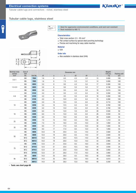
79v4grp
64
Electrical connection systems
Tubular cable lugs and connectors - nickel, stainless steel
Tubular cable lugs, stainless steel
Ideal for aggressive environmental conditions, acid and rust-resistant
Heat resistant to 400 °C
Characteristics
▪ Total cross-section: 0.5 - 95 mm²
▪ Flat contact surface by special steel punching technology
▪ Precise end machining for easy cable insertion
Material
▪ V2A
Order info
▪ Also available in stainless steel (V4A)
Nominal cross section mm²
Size ofboltdia. Part No.
Dimension mm Weight/100 pcs.
~ kg Packing unit/
pcs d1 a b d2 d4 l
0.5-1 M4 79V4 1.6 6 6.5 4.3 3.2 13 0.080 100
M5 79V5 1.6 6 7.5 5.3 3.2 14 0.080 100
1.5-2.5
M4 80V4 3.0 8 9.0 4.3 5.0 17 0.260 100
M5 80V5 3.0 8 9.0 5.5 5.0 17 0.190 100
M6 80V6 3.0 8 9.5 6.5 5.0 19 0.215 100
4-6
M4 81V4 4.0 9 9.0 4.3 6.0 18 0.260 100
M5 81V5 4.0 9 9.5 5.5 6.0 19 0.280 100
M6 81V6 4.0 9 10.0 6.5 6.0 19 0.280 100
10
M5 82V5 5.0 10 12.5 5.5 8.0 22 0.710 100
M6 82V6 5.0 10 12.5 6.5 8.0 22 0.780 100
M8 82V8 5.0 10 15.0 8.5 8.0 25 0.780 100
16
M5 83V5 6.0 13 12.0 5.5 8.0 28 0.500 50
M6 83V6 6.0 13 12.0 6.5 8.0 28 0.550 50
M8 83V8 6.0 13 15.0 8.5 8.0 29 0.600 50
25 M6 84V6 7.0 15 14.0 6.5 10.0 30 1.210 50
M8 84V8 7.0 15 16.0 8.5 10.0 32 1.850 50
35 M6 85V6 9.0 17 17.0 6.5 12.0 32 1.600 50
M8 85V8 9.0 17 17.0 8.5 12.0 35 1.850 50
50
M6 86V6 10.0 19 20.0 6.5 14.0 37 2.800 50
M8 86V8 10.0 19 20.0 8.5 14.0 37 2.600 50
M10 86V10 10.0 19 20.0 10.5 14.0 39 2.800 50
M12 86V12 10.0 19 20.0 13.0 14.0 43 2.960 50
70
M8 87V8 12.0 21 23.0 8.5 16.0 43 3.650 25
M10 87V10 12.0 21 23.0 10.5 16.0 44 3.930 25
M12 87V12 12.0 21 23.0 13.0 16.0 46 3.850 25
M16 87V16 12.0 21 26.0 17.0 16.0 46 3.960 25
95
M8 88V8 14.0 25 26.0 8.5 18.0 48 4.650 25
M10 88V10 14.0 25 26.0 10.5 18.0 48 5.610 25
M12 88V12 14.0 25 26.0 13.0 18.0 49 5.540 25
Tools: see chart page 68
Klauke Hauptkatalog EN_DIN A5.indb 64 07.10.2014 12:16:31
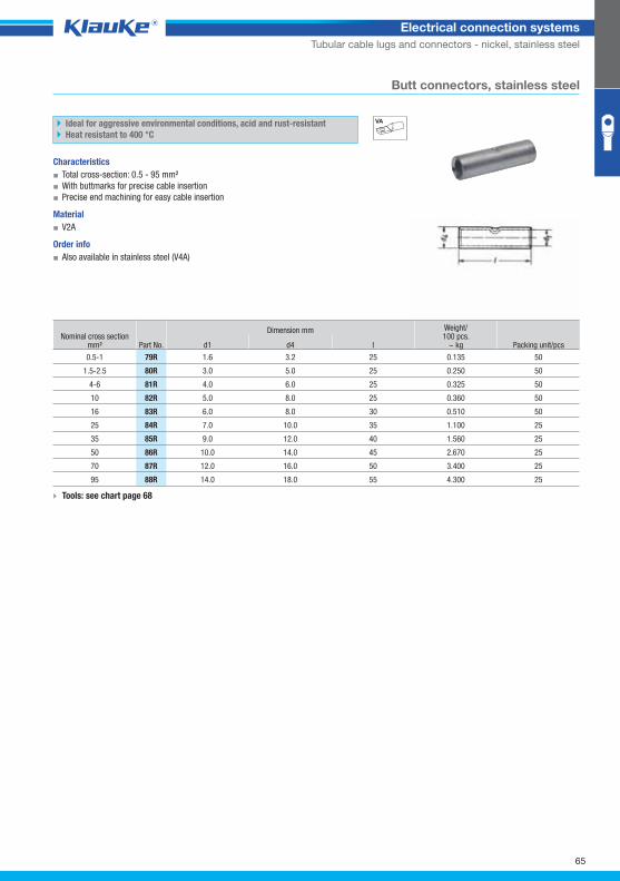
79rgrp
65
Electrical connection systems
Tubular cable lugs and connectors - nickel, stainless steel
Butt connectors, stainless steel
Ideal for aggressive environmental conditions, acid and rust-resistant
Heat resistant to 400 °C
Characteristics
▪ Total cross-section: 0.5 - 95 mm²
▪ With buttmarks for precise cable insertion
▪ Precise end machining for easy cable insertion
Material
▪ V2A
Order info
▪ Also available in stainless steel (V4A)
Nominal cross section mm² Part No.
Dimension mm Weight/100 pcs.
~ kg Packing unit/pcs d1 d4 l
0.5-1 79R 1.6 3.2 25 0.135 50
1.5-2.5 80R 3.0 5.0 25 0.250 50
4-6 81R 4.0 6.0 25 0.325 50
10 82R 5.0 8.0 25 0.360 50
16 83R 6.0 8.0 30 0.510 50
25 84R 7.0 10.0 35 1.100 25
35 85R 9.0 12.0 40 1.560 25
50 86R 10.0 14.0 45 2.670 25
70 87R 12.0 16.0 50 3.400 25
95 88R 14.0 18.0 55 4.300 25
Tools: see chart page 68
Klauke Hauptkatalog EN_DIN A5.indb 65 07.10.2014 12:16:31
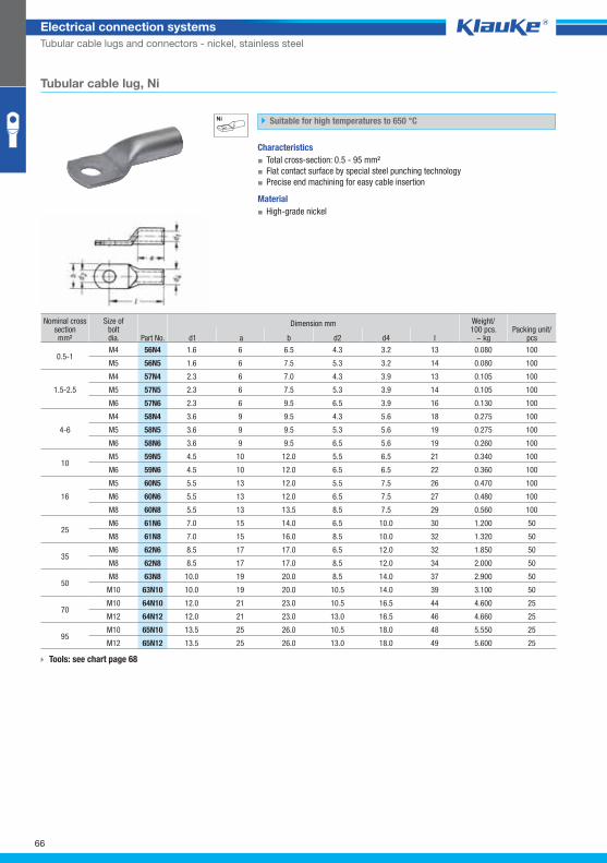
56n4grp
66
Electrical connection systems
Tubular cable lugs and connectors - nickel, stainless steel
Tubular cable lug, Ni
Suitable for high temperatures to 650 °C
Characteristics
▪ Total cross-section: 0.5 - 95 mm²
▪ Flat contact surface by special steel punching technology
▪ Precise end machining for easy cable insertion
Material
▪ High-grade nickel
Nominal cross section mm²
Size ofboltdia. Part No.
Dimension mm Weight/100 pcs.
~ kg Packing unit/
pcs d1 a b d2 d4 l
0.5-1 M4 56N4 1.6 6 6.5 4.3 3.2 13 0.080 100
M5 56N5 1.6 6 7.5 5.3 3.2 14 0.080 100
1.5-2.5
M4 57N4 2.3 6 7.0 4.3 3.9 13 0.105 100
M5 57N5 2.3 6 7.5 5.3 3.9 14 0.105 100
M6 57N6 2.3 6 9.5 6.5 3.9 16 0.130 100
4-6
M4 58N4 3.6 9 9.5 4.3 5.6 18 0.275 100
M5 58N5 3.6 9 9.5 5.3 5.6 19 0.275 100
M6 58N6 3.6 9 9.5 6.5 5.6 19 0.260 100
10 M5 59N5 4.5 10 12.0 5.5 6.5 21 0.340 100
M6 59N6 4.5 10 12.0 6.5 6.5 22 0.360 100
16
M5 60N5 5.5 13 12.0 5.5 7.5 26 0.470 100
M6 60N6 5.5 13 12.0 6.5 7.5 27 0.480 100
M8 60N8 5.5 13 13.5 8.5 7.5 29 0.560 100
25 M6 61N6 7.0 15 14.0 6.5 10.0 30 1.200 50
M8 61N8 7.0 15 16.0 8.5 10.0 32 1.320 50
35 M6 62N6 8.5 17 17.0 6.5 12.0 32 1.850 50
M8 62N8 8.5 17 17.0 8.5 12.0 34 2.000 50
50 M8 63N8 10.0 19 20.0 8.5 14.0 37 2.900 50
M10 63N10 10.0 19 20.0 10.5 14.0 39 3.100 50
70 M10 64N10 12.0 21 23.0 10.5 16.5 44 4.600 25
M12 64N12 12.0 21 23.0 13.0 16.5 46 4.660 25
95 M10 65N10 13.5 25 26.0 10.5 18.0 48 5.550 25
M12 65N12 13.5 25 26.0 13.0 18.0 49 5.600 25
Tools: see chart page 68
Klauke Hauptkatalog EN_DIN A5.indb 66 07.10.2014 12:16:31
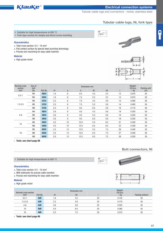
56c4grp
62rgrp
67
Electrical connection systems
Tubular cable lugs and connectors - nickel, stainless steel
Tubular cable lugs, Ni, fork type
Suitable for high temperatures to 650 °C
Fork-type version for simple and direct screw mounting
Characteristics
▪ Total cross-section: 0.5 - 16 mm²
▪ Flat contact surface by special steel punching technology
▪ Precise end machining for easy cable insertion
Material
▪ High-grade nickel
Nominal cross section mm²
Size ofboltdia. Part No.
Dimension mm Weight/100 pcs.
~ kg Packing unit/
pcs d1 a b d2 d4 l
0.5-1 M4 56C4 1.6 6 6.5 4.3 3.2 13 0.070 50
M5 56C5 1.6 6 7.5 5.3 3.2 14 0.075 50
1.5-2.5
M4 57C4 2.3 6 7.0 4.3 3.9 13 0.095 50
M5 57C5 2.3 6 7.5 5.3 3.9 14 0.095 50
M6 57C6 2.3 6 9.5 6.5 3.9 16 0.110 50
4-6
M4 58C4 3.6 9 9.5 4.3 5.6 18 0.250 50
M5 58C5 3.6 9 9.5 5.3 5.6 19 0.255 50
M6 58C6 3.6 9 9.5 6.5 5.6 19 0.235 50
10 M5 59C5 4.5 10 12.0 5.5 6.5 21 0.320 50
M6 59C6 4.5 10 12.0 6.5 6.5 22 0.340 50
16
M5 60C5 5.5 13 12.0 5.5 7.5 26 0.440 50
M6 60C6 5.5 13 12.0 6.5 7.5 27 0.450 50
M8 60C8 5.5 13 13.5 8.5 7.5 29 0.520 50
Tools: see chart page 68
Butt connectors, Ni
Suitable for high temperatures to 650 °C
Characteristics
▪ Total cross-section: 0.5 - 16 mm²
▪ With buttmarks for precise cable insertion
▪ Precise end machining for easy cable insertion
Material
▪ High-grade nickel
Nominal cross section mm² Part No.
Dimension mm Weight/100 pcs.
~ kg Packing unit/pcs d1 d4 l
0.5-1 62R 1.6 3.2 25 0.135 50
1.5-2.5 63R 2.3 3.9 25 0.170 50
4-6 64R 3.6 5.6 25 0.325 50
10 65R 4.5 6.5 25 0.360 50
16 66R 5.5 7.5 30 0.510 50
Tools: see chart page 68
Klauke Hauptkatalog EN_DIN A5.indb 67 07.10.2014 12:16:32
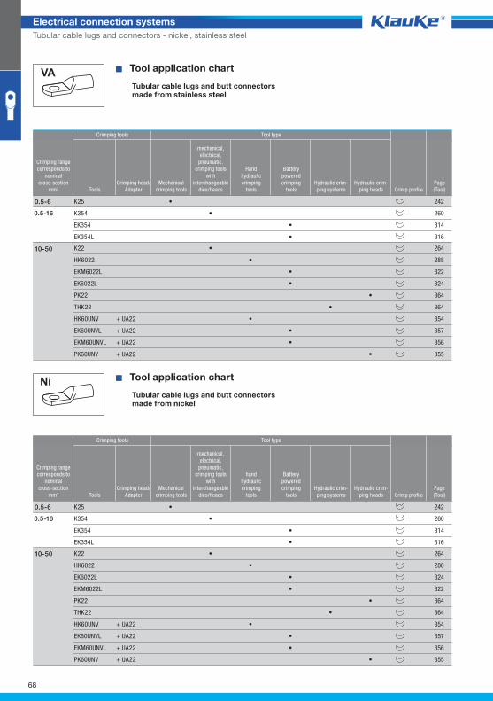
68
Electrical connection systems
Tubular cable lugs and connectors - nickel, stainless steel
^WZT_RKS_VA^
^WZT_RKS_Ni^
� Tool application chart
Tubular cable lugs and butt connectors made from stainless steel
Crimping tools Tool type
Crimping rangecorresponds to
nominalcross-section
mm² ToolsCrimping head/
AdapterMechanical
crimping tools
mechanical,electrical,
pneumatic, crimping tools
with interchangeable
dies/heads
Handhydraulic crimping
tools
Batterypowered crimping
toolsHydraulic crim-ping systems
Hydraulic crim-ping heads Crimp profile
Page(Tool)
K25 • 242
0.5-16 K354 • 260
EK354 • 314
EK354L • 316
0.5-6
K22 • 264
HK6022 • 288
EKM6022L • 322
EK6022L • 324
PK22 • 364
THK22 • 364
HK60UNV + UA22 • 354
EK60UNVL + UA22 • 357
EKM60UNVL + UA22 • 356
PK60UNV + UA22 • 355
10-50
� Tool application chart
Tubular cable lugs and butt connectorsmade from nickel
Crimping tools Tool type
Crimping rangecorresponds to
nominalcross-section
mm² ToolsCrimping head/
AdapterMechanical
crimping tools
mechanical,electrical,
pneumatic, crimping tools
with interchangeable
dies/heads
handhydraulic crimping
tools
Batterypowered crimping
toolsHydraulic crim-ping systems
Hydraulic crim-ping heads Crimp profile
Page(Tool)
K25 • 242
0.5-16 K354 • 260
EK354 • 314
EK354L • 316
0.5-6
K22 • 264
HK6022 • 288
EK6022L • 324
EKM6022L • 322
PK22 • 364
THK22 • 364
HK60UNV + UA22 • 354
EK60UNVL + UA22 • 357
EKM60UNVL + UA22 • 356
PK60UNV + UA22 • 355
10-50
Klauke Hauptkatalog EN_DIN A5.indb 68 07.10.2014 12:16:32

69
Electrical connection systems
Tubular cable lugs and connectors - nickel, stainless steel
Klauke Hauptkatalog EN_DIN A5.indb 69 07.10.2014 12:16:33
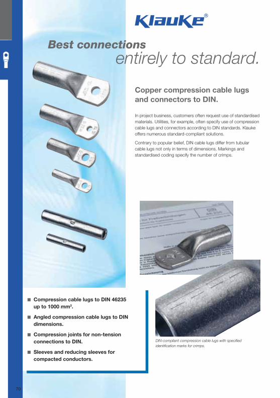
Best connections entirely to standard.
Copper compression cable lugs
and connectors to DIN.
◾ Compression cable lugs to DIN 46235
up to 1000 mm2.
◾ Angled compression cable lugs to DIN
dimensions.
◾ Compression joints for non-tension
connections to DIN.
◾ Sleeves and reducing sleeves for
compacted conductors.
DIN-compliant compression cable lugs with specifi ed
identifi cation marks for crimps.
In project business, customers often request use of standardised
materials. Utilities, for example, often specify use of compression
cable lugs and connectors according to DIN standards. Klauke
offers numerous standard-compliant solutions.
Contrary to popular belief, DIN cable lugs differ from tubular
cable lugs not only in terms of dimensions. Markings and
standardised coding specify the number of crimps.
70
Klauke Hauptkatalog EN_DIN A5.indb 70 07.10.2014 12:16:33
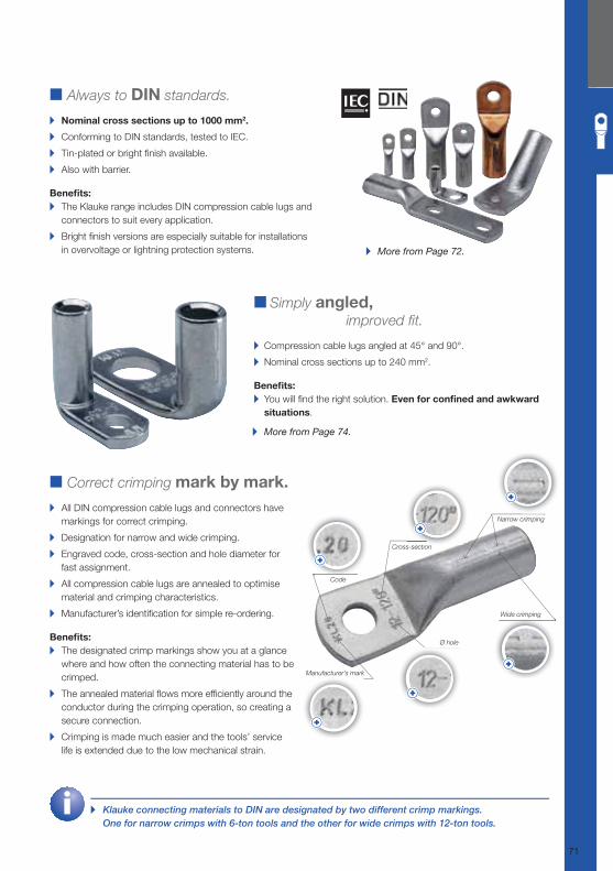
■ Always to DIN standards.
▸ Nominal cross sections up to 1000 mm2.
▸ Conforming to DIN standards, tested to IEC.
▸ Tin-plated or bright fi nish available.
▸ Also with barrier.
Benefi ts:
▸ The Klauke range includes DIN compression cable lugs and
connectors to suit every application.
▸ Bright fi nish versions are especially suitable for installations
in overvoltage or lightning protection systems.
■ Correct crimping mark by mark.
▸ All DIN compression cable lugs and connectors have
markings for correct crimping.
▸ Designation for narrow and wide crimping.
▸ Engraved code, cross-section and hole diameter for
fast assignment.
▸ All compression cable lugs are annealed to optimise
material and crimping characteristics.
▸ Manufacturer’s identifi cation for simple re-ordering.
Benefi ts:
▸ The designated crimp markings show you at a glance
where and how often the connecting material has to be
crimped.
▸ The annealed material fl ows more effi ciently around the
conductor during the crimping operation, so creating a
secure connection.
▸ Crimping is made much easier and the tools’ service
life is extended due to the low mechanical strain.
■ Simply angled, improved fi t.
▸ Compression cable lugs angled at 45° and 90°.
▸ Nominal cross sections up to 240 mm2.
Benefi ts:
▸ You will fi nd the right solution. Even for confi ned and awkward
situations.
▸ More from Page 74.
▸ More from Page 72.
▸ Klauke connecting materials to DIN are designated by two different crimp markings.
One for narrow crimps with 6-ton tools and the other for wide crimps with 12-ton tools.
Code
Cross-section
Ø hole
Narrow crimping
Wide crimping
Manufacturer’s mark
71
Klauke Hauptkatalog EN_DIN A5.indb 71 07.10.2014 12:16:34
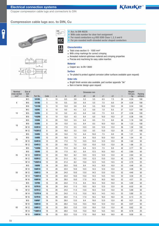
101r5grp
72
Electrical connection systems
Copper compression cable lugs and connectors to DIN
Compression cable lugs acc. to DIN, Cu
Acc. to DIN 46235
With code number for clear tool assignment
For round conductors e.g VDE 0295 Class 1, 2, 5 and 6
For pre-rounded multi-stranded sector shaped conductors
Characteristics
▪ Total cross-section: 6 - 1000 mm²
▪ With crimp markings for correct crimping
▪ Annealed material optimises material and crimping properties
▪ Precise end machining for easy cable insertion
Material
▪ Copper acc. to EN 13600
Surface
▪ Tin-plated to protect against corrosion (other surfaces available upon request)
Order info
▪ Bright finish version also available, part number appendix "bk"
▪ Item in barrier design upon request
Nominal cross section
mm²
Size ofboltdia. Part No. Code
Dimension mm Weight/100 pcs.
~ kg Packing unit/pcs a b d1 d2 d4 c1 c2 l
6
M 5 101R5 5 10 8.5 3.8 5.3 5.5 6.5 7.5 24 0.24 100
M 6 101R6 5 10 8.5 3.8 6.4 5.5 7.5 8.0 24 0.30 100
M 8 *101R8 5 10 13.0 3.8 8.4 5.5 10.0 10.0 24 0.34 100
10
M 5 102R5 6 10 9.0 4.5 5.3 6.0 7.0 8.5 27 0.37 100
M 6 102R6 6 10 9.0 4.5 6.4 6.0 7.5 8.5 27 0.36 100
M 8 *102R8 6 10 13.0 4.5 8.4 6.0 10.0 10.0 27 0.38 100
16
M 6 103R6 8 20 13.0 5.5 6.4 8.5 7.5 8.0 36 1.19 100
M 8 103R8 8 20 13.0 5.5 8.4 8.5 10.0 10.0 36 1.22 100
M 10 103R10 8 20 17.0 5.5 10.5 8.5 12.0 12.0 36 1.30 100
M 12 *103R12 8 20 18.0 5.5 13.0 8.5 13.0 13.0 36 1.27 100
25
M 6 104R6 10 20 14.0 7.0 6.4 10.0 7.5 8.0 38 1.51 50
M 8 104R8 10 20 16.0 7.0 8.4 10.0 10.0 10.0 38 1.54 50
M 10 104R10 10 20 17.0 7.0 10.5 10.0 12.0 12.0 38 1.62 50
M 12 104R12 10 20 19.0 7.0 13.0 10.0 13.0 13.0 38 1.66 25
35
M 6 *105R6 12 20 17.0 8.2 6.4 12.5 7.5 8.0 42 2.77 50
M 8 105R8 12 20 17.0 8.2 8.4 12.5 10.0 10.0 42 2.85 50
M 10 105R10 12 20 19.0 8.2 10.5 12.5 12.0 12.0 42 2.84 50
M 12 105R12 12 20 21.0 8.2 13.0 12.5 13.0 13.0 42 2.79 50
M 14 *105R14 12 20 21.0 8.2 15.0 12.5 14.5 14.5 42 2.70 25
50
M 8 106R8 14 28 20.0 10.0 8.4 14.5 10.0 10.0 52 4.46 50
M 10 106R10 14 28 22.0 10.0 10.5 14.5 12.0 12.0 52 4.48 50
M 12 106R12 14 28 24.0 10.0 13.0 14.5 13.0 13.0 52 4.40 50
M 14 *106R14 14 28 24.0 10.0 15.0 14.5 14.5 14.5 52 4.30 25
M 16 106R16 14 28 28.0 10.0 17.0 14.5 16.0 16.0 52 4.57 25
70
M 8 107R8 16 28 24.0 11.5 8.4 16.5 10.0 10.0 55 5.92 50
M 10 107R10 16 28 24.0 11.5 10.5 16.5 12.0 12.0 55 6.02 50
M 12 107R12 16 28 24.0 11.5 13.0 16.5 13.0 13.0 55 5.89 50
M 14 *107R14 16 28 24.0 11.5 15.0 16.5 14.5 14.5 55 5.80 25
M 16 107R16 16 28 30.0 11.5 17.0 16.5 16.0 16.0 55 6.13 25
95
M 8 108R8* 18 35 28.0 13.5 8.4 19.0 12.0 12.0 65 9.21 25
M 10 108R10 18 35 28.0 13.5 10.5 19.0 12.0 12.0 65 8.97 50
M 12 108R12 18 35 28.0 13.5 13.0 19.0 13.0 13.0 65 8.62 50
M 14 *108R14 18 35 28.0 13.5 15.0 19.0 14.5 14.5 65 8.78 25
M 16 108R16 18 35 32.0 13.5 17.0 19.0 16.0 16.0 65 9.00 50
Klauke Hauptkatalog EN_DIN A5.indb 72 07.10.2014 12:16:35
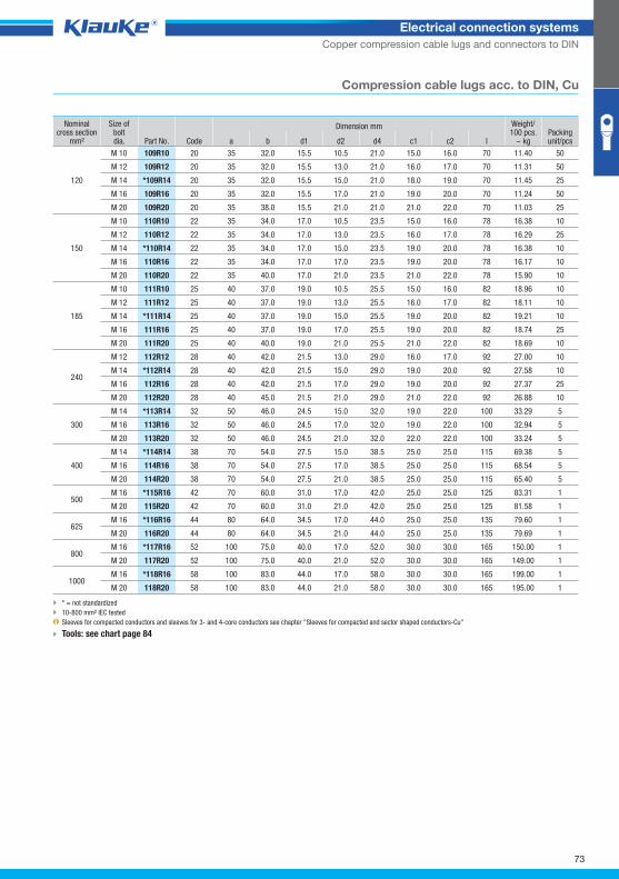
73
Electrical connection systems
Copper compression cable lugs and connectors to DIN
Compression cable lugs acc. to DIN, Cu
Nominal cross section
mm²
Size ofboltdia. Part No. Code
Dimension mm Weight/100 pcs.
~ kg Packing unit/pcs a b d1 d2 d4 c1 c2 l
120
M 10 109R10 20 35 32.0 15.5 10.5 21.0 15.0 16.0 70 11.40 50
M 12 109R12 20 35 32.0 15.5 13.0 21.0 16.0 17.0 70 11.31 50
M 14 *109R14 20 35 32.0 15.5 15.0 21.0 18.0 19.0 70 11.45 25
M 16 109R16 20 35 32.0 15.5 17.0 21.0 19.0 20.0 70 11.24 50
M 20 109R20 20 35 38.0 15.5 21.0 21.0 21.0 22.0 70 11.03 25
150
M 10 110R10 22 35 34.0 17.0 10.5 23.5 15.0 16.0 78 16.38 10
M 12 110R12 22 35 34.0 17.0 13.0 23.5 16.0 17.0 78 16.29 25
M 14 *110R14 22 35 34.0 17.0 15.0 23.5 19.0 20.0 78 16.38 10
M 16 110R16 22 35 34.0 17.0 17.0 23.5 19.0 20.0 78 16.17 10
M 20 110R20 22 35 40.0 17.0 21.0 23.5 21.0 22.0 78 15.90 10
185
M 10 111R10 25 40 37.0 19.0 10.5 25.5 15.0 16.0 82 18.96 10
M 12 111R12 25 40 37.0 19.0 13.0 25.5 16.0 17.0 82 18.11 10
M 14 *111R14 25 40 37.0 19.0 15.0 25.5 19.0 20.0 82 19.21 10
M 16 111R16 25 40 37.0 19.0 17.0 25.5 19.0 20.0 82 18.74 25
M 20 111R20 25 40 40.0 19.0 21.0 25.5 21.0 22.0 82 18.69 10
240
M 12 112R12 28 40 42.0 21.5 13.0 29.0 16.0 17.0 92 27.00 10
M 14 *112R14 28 40 42.0 21.5 15.0 29.0 19.0 20.0 92 27.58 10
M 16 112R16 28 40 42.0 21.5 17.0 29.0 19.0 20.0 92 27.37 25
M 20 112R20 28 40 45.0 21.5 21.0 29.0 21.0 22.0 92 26.88 10
300
M 14 *113R14 32 50 46.0 24.5 15.0 32.0 19.0 22.0 100 33.29 5
M 16 113R16 32 50 46.0 24.5 17.0 32.0 19.0 22.0 100 32.94 5
M 20 113R20 32 50 46.0 24.5 21.0 32.0 22.0 22.0 100 33.24 5
400
M 14 *114R14 38 70 54.0 27.5 15.0 38.5 25.0 25.0 115 69.38 5
M 16 114R16 38 70 54.0 27.5 17.0 38.5 25.0 25.0 115 68.54 5
M 20 114R20 38 70 54.0 27.5 21.0 38.5 25.0 25.0 115 65.40 5
500 M 16 *115R16 42 70 60.0 31.0 17.0 42.0 25.0 25.0 125 83.31 1
M 20 115R20 42 70 60.0 31.0 21.0 42.0 25.0 25.0 125 81.58 1
625 M 16 *116R16 44 80 64.0 34.5 17.0 44.0 25.0 25.0 135 79.60 1
M 20 116R20 44 80 64.0 34.5 21.0 44.0 25.0 25.0 135 79.69 1
800 M 16 *117R16 52 100 75.0 40.0 17.0 52.0 30.0 30.0 165 150.00 1
M 20 117R20 52 100 75.0 40.0 21.0 52.0 30.0 30.0 165 149.00 1
1000 M 16 *118R16 58 100 83.0 44.0 17.0 58.0 30.0 30.0 165 199.00 1
M 20 118R20 58 100 83.0 44.0 21.0 58.0 30.0 30.0 165 195.00 1
* = not standardized
10-800 mm² IEC tested
Sleeves for compacted conductors and sleeves for 3- and 4-core conductors see chapter "Sleeves for compacted and sector shaped conductors-Cu"
Tools: see chart page 84
Klauke Hauptkatalog EN_DIN A5.indb 73 07.10.2014 12:16:36
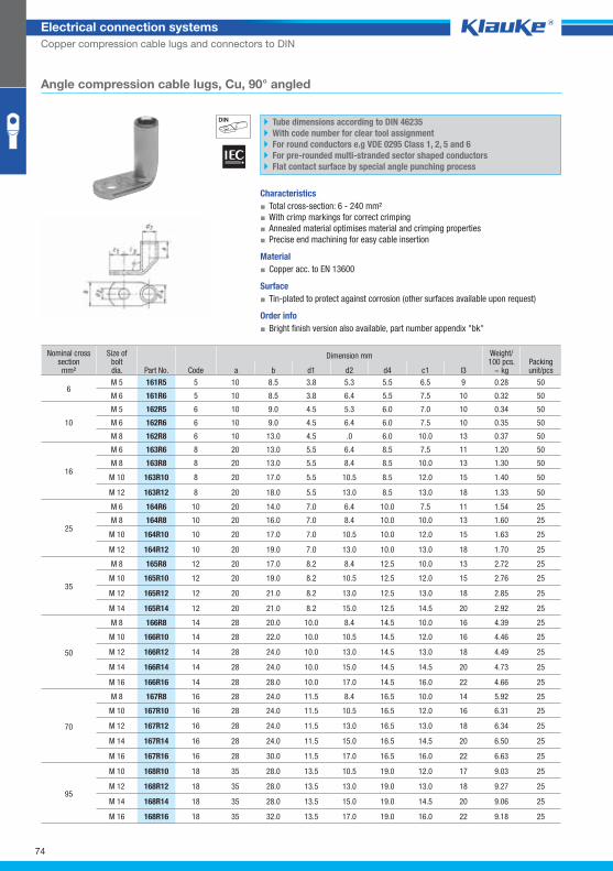
161r5grp
74
Electrical connection systems
Copper compression cable lugs and connectors to DIN
Angle compression cable lugs, Cu, 90° angled
Tube dimensions according to DIN 46235
With code number for clear tool assignment
For round conductors e.g VDE 0295 Class 1, 2, 5 and 6
For pre-rounded multi-stranded sector shaped conductors
Flat contact surface by special angle punching process
Characteristics
▪ Total cross-section: 6 - 240 mm²
▪ With crimp markings for correct crimping
▪ Annealed material optimises material and crimping properties
▪ Precise end machining for easy cable insertion
Material
▪ Copper acc. to EN 13600
Surface
▪ Tin-plated to protect against corrosion (other surfaces available upon request)
Order info
▪ Bright finish version also available, part number appendix "bk"
Nominal cross section mm²
Size ofboltdia. Part No. Code
Dimension mm Weight/100 pcs.
~ kg Packing unit/pcs a b d1 d2 d4 c1 l3
6 M 5 161R5 5 10 8.5 3.8 5.3 5.5 6.5 9 0.28 50
M 6 161R6 5 10 8.5 3.8 6.4 5.5 7.5 10 0.32 50
10
M 5 162R5 6 10 9.0 4.5 5.3 6.0 7.0 10 0.34 50
M 6 162R6 6 10 9.0 4.5 6.4 6.0 7.5 10 0.35 50
M 8 162R8 6 10 13.0 4.5 .0 6.0 10.0 13 0.37 50
16
M 6 163R6 8 20 13.0 5.5 6.4 8.5 7.5 11 1.20 50
M 8 163R8 8 20 13.0 5.5 8.4 8.5 10.0 13 1.30 50
M 10 163R10 8 20 17.0 5.5 10.5 8.5 12.0 15 1.40 50
M 12 163R12 8 20 18.0 5.5 13.0 8.5 13.0 18 1.33 50
25
M 6 164R6 10 20 14.0 7.0 6.4 10.0 7.5 11 1.54 25
M 8 164R8 10 20 16.0 7.0 8.4 10.0 10.0 13 1.60 25
M 10 164R10 10 20 17.0 7.0 10.5 10.0 12.0 15 1.63 25
M 12 164R12 10 20 19.0 7.0 13.0 10.0 13.0 18 1.70 25
35
M 8 165R8 12 20 17.0 8.2 8.4 12.5 10.0 13 2.72 25
M 10 165R10 12 20 19.0 8.2 10.5 12.5 12.0 15 2.76 25
M 12 165R12 12 20 21.0 8.2 13.0 12.5 13.0 18 2.85 25
M 14 165R14 12 20 21.0 8.2 15.0 12.5 14.5 20 2.92 25
50
M 8 166R8 14 28 20.0 10.0 8.4 14.5 10.0 16 4.39 25
M 10 166R10 14 28 22.0 10.0 10.5 14.5 12.0 16 4.46 25
M 12 166R12 14 28 24.0 10.0 13.0 14.5 13.0 18 4.49 25
M 14 166R14 14 28 24.0 10.0 15.0 14.5 14.5 20 4.73 25
M 16 166R16 14 28 28.0 10.0 17.0 14.5 16.0 22 4.66 25
70
M 8 167R8 16 28 24.0 11.5 8.4 16.5 10.0 14 5.92 25
M 10 167R10 16 28 24.0 11.5 10.5 16.5 12.0 16 6.31 25
M 12 167R12 16 28 24.0 11.5 13.0 16.5 13.0 18 6.34 25
M 14 167R14 16 28 24.0 11.5 15.0 16.5 14.5 20 6.50 25
M 16 167R16 16 28 30.0 11.5 17.0 16.5 16.0 22 6.63 25
95
M 10 168R10 18 35 28.0 13.5 10.5 19.0 12.0 17 9.03 25
M 12 168R12 18 35 28.0 13.5 13.0 19.0 13.0 18 9.27 25
M 14 168R14 18 35 28.0 13.5 15.0 19.0 14.5 20 9.06 25
M 16 168R16 18 35 32.0 13.5 17.0 19.0 16.0 22 9.18 25
Klauke Hauptkatalog EN_DIN A5.indb 74 07.10.2014 12:16:36
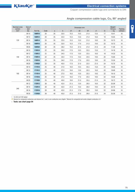
75
Electrical connection systems
Copper compression cable lugs and connectors to DIN
Angle compression cable lugs, Cu, 90° angled
Nominal cross section mm²
Size ofboltdia. Part No. Code
Dimension mm Weight/100 pcs.
~ kg Packing unit/pcs a b d1 d2 d4 c1 l3
120
M 10 169R10 20 35 32.0 15.5 10.5 21.0 15.0 17 10.41 10
M 12 169R12 20 35 32.0 15.5 13.0 21.0 16.0 18 10.65 10
M 14 169R14 20 35 32.0 15.5 15.0 21.0 18.0 20 10.75 10
M 16 169R16 20 35 32.0 15.5 17.0 21.0 19.0 22 10.72 10
M 20 169R20 20 35 38.0 15.5 21.0 21.0 21.0 24 11.00 10
150
M 10 170R10 22 35 34.0 17.0 10.5 23.5 15.0 17 14.18 10
M 12 170R12 22 35 34.0 17.0 13.0 23.5 16.0 18 14.33 10
M 14 170R14 22 35 34.0 17.0 15.0 23.5 19.0 20 15.60 10
M 16 170R16 22 35 34.0 17.0 17.0 23.5 19.0 22 15.24 10
M 20 170R20 22 35 40.0 17.0 21.0 23.5 21.0 24 15.70 10
185
M 10 171R10 25 40 37.0 19.0 10.5 25.5 15.0 22 18.60 10
M 12 171R12 25 40 37.0 19.0 13.0 25.5 16.0 22 18.69 10
M 14 171R14 25 40 37.0 19.0 15.0 25.5 19.0 22 19.10 10
M 16 171R16 25 40 37.0 19.0 17.0 25.5 19.0 22 19.00 10
M 20 171R20 25 40 40.0 19.0 21.0 25.5 21.0 24 18.72 10
240
M 12 172R12 28 40 42.0 21.5 13.0 29.0 16.0 22 25.09 10
M 14 172R14 28 40 42.0 21.5 15.0 29.0 19.0 22 25.70 10
M 16 172R16 28 40 42.0 21.5 17.0 29.0 19.0 22 24.96 10
M 20 172R20 28 40 45.0 21.5 21.0 29.0 21.0 24 25.26 10
10-240 mm² IEC tested
Sleeves for compacted conductors and sleeves for 3- and 4-core conductors see chapter "Sleeves for compacted and sector shaped conductors-Cu"
Tools: see chart page 84
Klauke Hauptkatalog EN_DIN A5.indb 75 07.10.2014 12:16:37
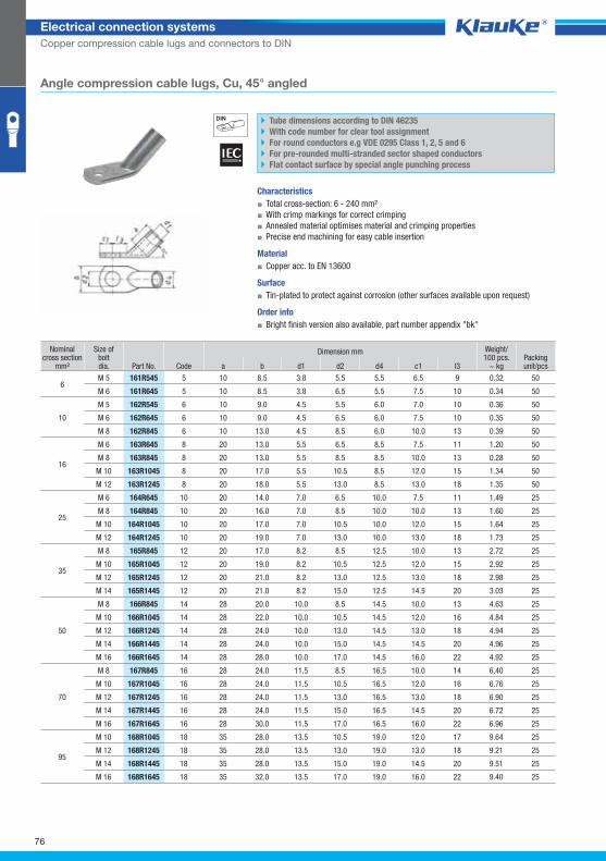
161r545grp
76
Electrical connection systems
Copper compression cable lugs and connectors to DIN
Angle compression cable lugs, Cu, 45° angled
Tube dimensions according to DIN 46235
With code number for clear tool assignment
For round conductors e.g VDE 0295 Class 1, 2, 5 and 6
For pre-rounded multi-stranded sector shaped conductors
Flat contact surface by special angle punching process
Characteristics
▪ Total cross-section: 6 - 240 mm²
▪ With crimp markings for correct crimping
▪ Annealed material optimises material and crimping properties
▪ Precise end machining for easy cable insertion
Material
▪ Copper acc. to EN 13600
Surface
▪ Tin-plated to protect against corrosion (other surfaces available upon request)
Order info
▪ Bright finish version also available, part number appendix "bk"
Nominal cross section
mm²
Size ofboltdia. Part No. Code
Dimension mm Weight/100 pcs.
~ kg Packing unit/pcs a b d1 d2 d4 c1 l3
6 M 5 161R545 5 10 8.5 3.8 5.5 5.5 6.5 9 0.32 50
M 6 161R645 5 10 8.5 3.8 6.5 5.5 7.5 10 0.34 50
10
M 5 162R545 6 10 9.0 4.5 5.5 6.0 7.0 10 0.36 50
M 6 162R645 6 10 9.0 4.5 6.5 6.0 7.5 10 0.35 50
M 8 162R845 6 10 13.0 4.5 8.5 6.0 10.0 13 0.39 50
16
M 6 163R645 8 20 13.0 5.5 6.5 8.5 7.5 11 1.20 50
M 8 163R845 8 20 13.0 5.5 8.5 8.5 10.0 13 0.28 50
M 10 163R1045 8 20 17.0 5.5 10.5 8.5 12.0 15 1.34 50
M 12 163R1245 8 20 18.0 5.5 13.0 8.5 13.0 18 1.35 50
25
M 6 164R645 10 20 14.0 7.0 6.5 10.0 7.5 11 1.49 25
M 8 164R845 10 20 16.0 7.0 8.5 10.0 10.0 13 1.60 25
M 10 164R1045 10 20 17.0 7.0 10.5 10.0 12.0 15 1.64 25
M 12 164R1245 10 20 19.0 7.0 13.0 10.0 13.0 18 1.73 25
35
M 8 165R845 12 20 17.0 8.2 8.5 12.5 10.0 13 2.72 25
M 10 165R1045 12 20 19.0 8.2 10.5 12.5 12.0 15 2.92 25
M 12 165R1245 12 20 21.0 8.2 13.0 12.5 13.0 18 2.98 25
M 14 165R1445 12 20 21.0 8.2 15.0 12.5 14.5 20 3.03 25
50
M 8 166R845 14 28 20.0 10.0 8.5 14.5 10.0 13 4.63 25
M 10 166R1045 14 28 22.0 10.0 10.5 14.5 12.0 16 4.84 25
M 12 166R1245 14 28 24.0 10.0 13.0 14.5 13.0 18 4.94 25
M 14 166R1445 14 28 24.0 10.0 15.0 14.5 14.5 20 4.96 25
M 16 166R1645 14 28 28.0 10.0 17.0 14.5 16.0 22 4.92 25
70
M 8 167R845 16 28 24.0 11.5 8.5 16.5 10.0 14 6.40 25
M 10 167R1045 16 28 24.0 11.5 10.5 16.5 12.0 16 6.76 25
M 12 167R1245 16 28 24.0 11.5 13.0 16.5 13.0 18 6.90 25
M 14 167R1445 16 28 24.0 11.5 15.0 16.5 14.5 20 6.72 25
M 16 167R1645 16 28 30.0 11.5 17.0 16.5 16.0 22 6.96 25
95
M 10 168R1045 18 35 28.0 13.5 10.5 19.0 12.0 17 9.64 25
M 12 168R1245 18 35 28.0 13.5 13.0 19.0 13.0 18 9.21 25
M 14 168R1445 18 35 28.0 13.5 15.0 19.0 14.5 20 9.51 25
M 16 168R1645 18 35 32.0 13.5 17.0 19.0 16.0 22 9.40 25
Klauke Hauptkatalog EN_DIN A5.indb 76 07.10.2014 12:16:37
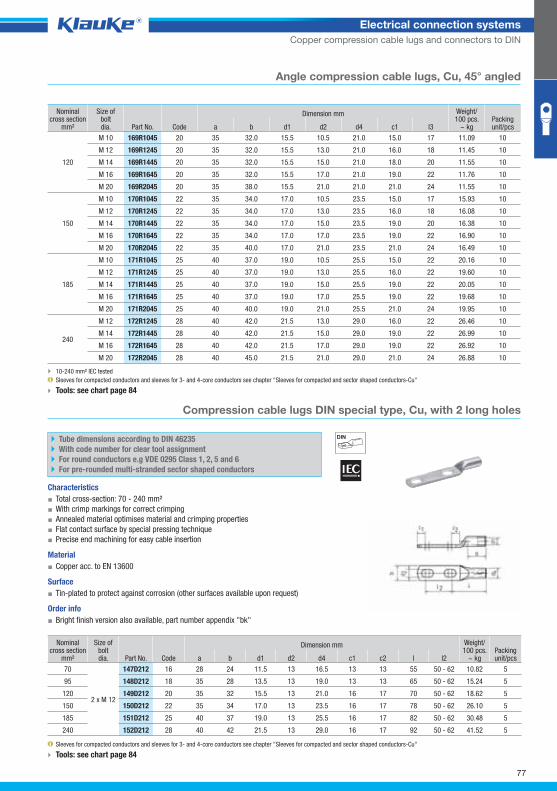
147d212grp
77
Electrical connection systems
Copper compression cable lugs and connectors to DIN
Angle compression cable lugs, Cu, 45° angled
Nominal cross section
mm²
Size ofboltdia. Part No. Code
Dimension mm Weight/100 pcs.
~ kg Packing unit/pcs a b d1 d2 d4 c1 l3
120
M 10 169R1045 20 35 32.0 15.5 10.5 21.0 15.0 17 11.09 10
M 12 169R1245 20 35 32.0 15.5 13.0 21.0 16.0 18 11.45 10
M 14 169R1445 20 35 32.0 15.5 15.0 21.0 18.0 20 11.55 10
M 16 169R1645 20 35 32.0 15.5 17.0 21.0 19.0 22 11.76 10
M 20 169R2045 20 35 38.0 15.5 21.0 21.0 21.0 24 11.55 10
150
M 10 170R1045 22 35 34.0 17.0 10.5 23.5 15.0 17 15.93 10
M 12 170R1245 22 35 34.0 17.0 13.0 23.5 16.0 18 16.08 10
M 14 170R1445 22 35 34.0 17.0 15.0 23.5 19.0 20 16.38 10
M 16 170R1645 22 35 34.0 17.0 17.0 23.5 19.0 22 16.90 10
M 20 170R2045 22 35 40.0 17.0 21.0 23.5 21.0 24 16.49 10
185
M 10 171R1045 25 40 37.0 19.0 10.5 25.5 15.0 22 20.16 10
M 12 171R1245 25 40 37.0 19.0 13.0 25.5 16.0 22 19.60 10
M 14 171R1445 25 40 37.0 19.0 15.0 25.5 19.0 22 20.05 10
M 16 171R1645 25 40 37.0 19.0 17.0 25.5 19.0 22 19.68 10
M 20 171R2045 25 40 40.0 19.0 21.0 25.5 21.0 24 19.95 10
240
M 12 172R1245 28 40 42.0 21.5 13.0 29.0 16.0 22 26.46 10
M 14 172R1445 28 40 42.0 21.5 15.0 29.0 19.0 22 26.99 10
M 16 172R1645 28 40 42.0 21.5 17.0 29.0 19.0 22 26.92 10
M 20 172R2045 28 40 45.0 21.5 21.0 29.0 21.0 24 26.88 10
10-240 mm² IEC tested
Sleeves for compacted conductors and sleeves for 3- and 4-core conductors see chapter "Sleeves for compacted and sector shaped conductors-Cu"
Tools: see chart page 84
Compression cable lugs DIN special type, Cu, with 2 long holes
Tube dimensions according to DIN 46235
With code number for clear tool assignment
For round conductors e.g VDE 0295 Class 1, 2, 5 and 6
For pre-rounded multi-stranded sector shaped conductors
Characteristics
▪ Total cross-section: 70 - 240 mm²
▪ With crimp markings for correct crimping
▪ Annealed material optimises material and crimping properties
▪ Flat contact surface by special pressing technique
▪ Precise end machining for easy cable insertion
Material
▪ Copper acc. to EN 13600
Surface
▪ Tin-plated to protect against corrosion (other surfaces available upon request)
Order info
▪ Bright finish version also available, part number appendix "bk"
Nominal cross section
mm²
Size ofboltdia. Part No. Code
Dimension mm Weight/100 pcs.
~ kg Packing unit/pcs a b d1 d2 d4 c1 c2 l l2
70
2 x M 12
147D212 16 28 24 11.5 13 16.5 13 13 55 50 - 62 10.82 5
95 148D212 18 35 28 13.5 13 19.0 13 13 65 50 - 62 15.24 5
120 149D212 20 35 32 15.5 13 21.0 16 17 70 50 - 62 18.62 5
150 150D212 22 35 34 17.0 13 23.5 16 17 78 50 - 62 26.10 5
185 151D212 25 40 37 19.0 13 25.5 16 17 82 50 - 62 30.48 5
240 152D212 28 40 42 21.5 13 29.0 16 17 92 50 - 62 41.52 5
Sleeves for compacted conductors and sleeves for 3- and 4-core conductors see chapter "Sleeves for compacted and sector shaped conductors-Cu"
Tools: see chart page 84
Klauke Hauptkatalog EN_DIN A5.indb 77 07.10.2014 12:16:37
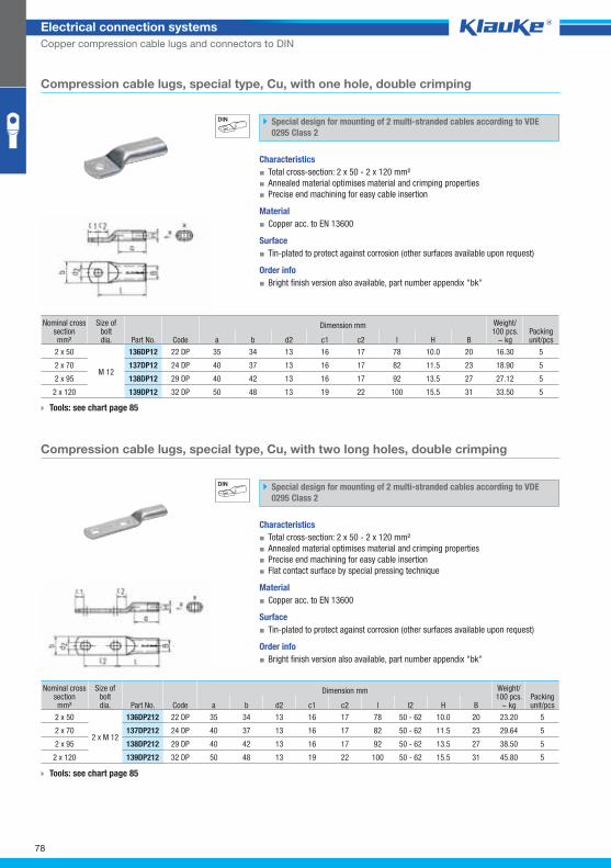
136dp12grp
136dp212grp
78
Electrical connection systems
Copper compression cable lugs and connectors to DIN
Compression cable lugs, special type, Cu, with one hole, double crimping
Special design for mounting of 2 multi-stranded cables according to VDE
0295 Class 2
Characteristics
▪ Total cross-section: 2 x 50 - 2 x 120 mm²
▪ Annealed material optimises material and crimping properties
▪ Precise end machining for easy cable insertion
Material
▪ Copper acc. to EN 13600
Surface
▪ Tin-plated to protect against corrosion (other surfaces available upon request)
Order info
▪ Bright finish version also available, part number appendix "bk"
Nominal cross section mm²
Size ofboltdia. Part No. Code
Dimension mm Weight/100 pcs.
~ kg Packing unit/pcs a b d2 c1 c2 l H B
2 x 50
M 12
136DP12 22 DP 35 34 13 16 17 78 10.0 20 16.30 5
2 x 70 137DP12 24 DP 40 37 13 16 17 82 11.5 23 18.90 5
2 x 95 138DP12 29 DP 40 42 13 16 17 92 13.5 27 27.12 5
2 x 120 139DP12 32 DP 50 48 13 19 22 100 15.5 31 33.50 5
Tools: see chart page 85
Compression cable lugs, special type, Cu, with two long holes, double crimping
Special design for mounting of 2 multi-stranded cables according to VDE
0295 Class 2
Characteristics
▪ Total cross-section: 2 x 50 - 2 x 120 mm²
▪ Annealed material optimises material and crimping properties
▪ Precise end machining for easy cable insertion
▪ Flat contact surface by special pressing technique
Material
▪ Copper acc. to EN 13600
Surface
▪ Tin-plated to protect against corrosion (other surfaces available upon request)
Order info
▪ Bright finish version also available, part number appendix "bk"
Nominal cross section mm²
Size ofboltdia. Part No. Code
Dimension mm Weight/100 pcs.
~ kg Packing unit/pcs a b d2 c1 c2 l l2 H B
2 x 50
2 x M 12
136DP212 22 DP 35 34 13 16 17 78 50 - 62 10.0 20 23.20 5
2 x 70 137DP212 24 DP 40 37 13 16 17 82 50 - 62 11.5 23 29.64 5
2 x 95 138DP212 29 DP 40 42 13 16 17 92 50 - 62 13.5 27 38.50 5
2 x 120 139DP212 32 DP 50 48 13 19 22 100 50 - 62 15.5 31 45.80 5
Tools: see chart page 85
Klauke Hauptkatalog EN_DIN A5.indb 78 07.10.2014 12:16:38
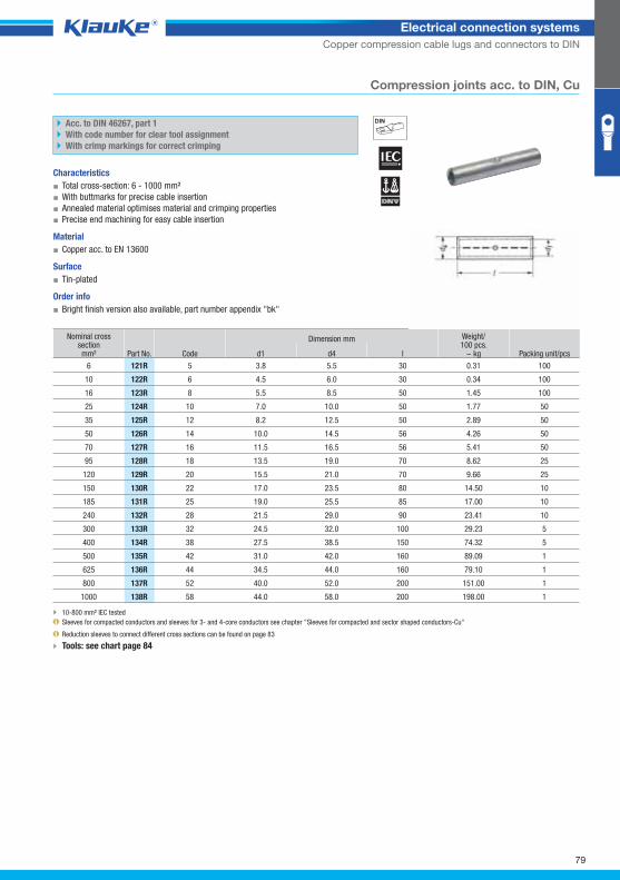
121rgrp
79
Electrical connection systems
Copper compression cable lugs and connectors to DIN
Compression joints acc. to DIN, Cu
Acc. to DIN 46267, part 1
With code number for clear tool assignment
With crimp markings for correct crimping
Characteristics
▪ Total cross-section: 6 - 1000 mm²
▪ With buttmarks for precise cable insertion
▪ Annealed material optimises material and crimping properties
▪ Precise end machining for easy cable insertion
Material
▪ Copper acc. to EN 13600
Surface
▪ Tin-plated
Order info
▪ Bright finish version also available, part number appendix "bk"
Nominal cross section mm² Part No. Code
Dimension mm Weight/100 pcs.
~ kg Packing unit/pcs d1 d4 l
6 121R 5 3.8 5.5 30 0.31 100
10 122R 6 4.5 6.0 30 0.34 100
16 123R 8 5.5 8.5 50 1.45 100
25 124R 10 7.0 10.0 50 1.77 50
35 125R 12 8.2 12.5 50 2.89 50
50 126R 14 10.0 14.5 56 4.26 50
70 127R 16 11.5 16.5 56 5.41 50
95 128R 18 13.5 19.0 70 8.62 25
120 129R 20 15.5 21.0 70 9.66 25
150 130R 22 17.0 23.5 80 14.50 10
185 131R 25 19.0 25.5 85 17.00 10
240 132R 28 21.5 29.0 90 23.41 10
300 133R 32 24.5 32.0 100 29.23 5
400 134R 38 27.5 38.5 150 74.32 5
500 135R 42 31.0 42.0 160 89.09 1
625 136R 44 34.5 44.0 160 79.10 1
800 137R 52 40.0 52.0 200 151.00 1
1000 138R 58 44.0 58.0 200 198.00 1
10-800 mm² IEC tested
Sleeves for compacted conductors and sleeves for 3- and 4-core conductors see chapter "Sleeves for compacted and sector shaped conductors-Cu"
Reduction sleeves to connect different cross sections can be found on page 83
Tools: see chart page 84
Klauke Hauptkatalog EN_DIN A5.indb 79 07.10.2014 12:16:38
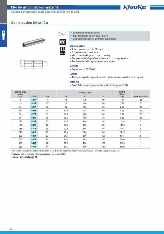
523rgrp
80
Electrical connection systems
Copper compression cable lugs and connectors to DIN
Compression joints, Cu
Barrier design with oil stop
Tube dimension to DIN 46267 part 1
With code number for clear tool assignment
Characteristics
▪ Total cross-section: 16 - 625 mm²
▪ For non-tension connections
▪ With crimp markings for correct crimping
▪ Annealed material optimises material and crimping properties
▪ Precise end machining for easy cable insertion
Material
▪ Copper acc. to EN 13600
Surface
▪ Tin-plated to protect against corrosion (other surfaces available upon request)
Order info
▪ Bright finish version also available, part number appendix "bk"
Nominal cross section mm² Part No. Code
Dimension mm Weight/100 pcs.
~ kg Packing unit/pcs d1 d4 l
16 523R 8 5.5 8.5 50 1.54 25
25 524R 10 7.0 10.0 50 1.84 25
35 525R 12 8.2 12.5 50 2.99 25
50 526R 14 10.0 14.5 56 4.46 25
70 527R 16 11.5 16.5 56 5.61 25
95 528R 18 13.5 19.0 70 8.88 25
120 529R 20 15.5 21.0 70 10.06 5
150 530R 22 17.0 23.5 80 14.89 5
185 531R 25 19.0 25.5 85 17.57 5
240 532R 28 21.5 29.0 90 24.23 5
300 533R 32 24.5 32.0 100 30.15 5
400 534R 38 27.5 38.5 150 75.60 5
500 535R 42 31.0 42.0 160 92.00 1
625 536R 44 34.5 44.0 160 81.50 1
Sleeves for compacted conductors and sleeves for 3- and 4-core conductors see chapter "Sleeves for compacted and sector shaped conductors-Cu"
Reduction sleeves to connect different cross sections can be found at 83
Tools: see chart page 84
Klauke Hauptkatalog EN_DIN A5.indb 80 07.10.2014 12:16:39
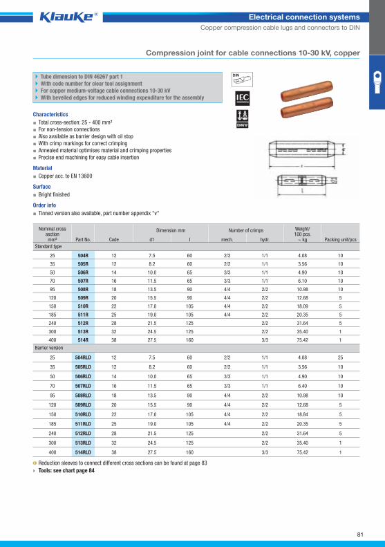
504R_GRP01
81
Electrical connection systems
Copper compression cable lugs and connectors to DIN
Compression joint for cable connections 10-30 kV, copper
Tube dimension to DIN 46267 part 1
With code number for clear tool assignment
For copper medium-voltage cable connections 10-30 kV
With bevelled edges for reduced winding expenditure for the assembly
Characteristics
▪ Total cross-section: 25 - 400 mm²
▪ For non-tension connections
▪ Also available as barrier design with oil stop
▪ With crimp markings for correct crimping
▪ Annealed material optimises material and crimping properties
▪ Precise end machining for easy cable insertion
Material
▪ Copper acc. to EN 13600
Surface
▪ Bright finished
Order info
▪ Tinned version also available, part number appendix "v"
Nominal cross section mm² Part No. Code
Dimension mm Number of crimps Weight/100 pcs.
~ kg Packing unit/pcs d1 l mech. hydr.
Standard type
25 504R 12 7.5 60 2/2 1/1 4.08 10
35 505R 12 8.2 60 2/2 1/1 3.56 10
50 506R 14 10.0 65 3/3 1/1 4.90 10
70 507R 16 11.5 65 3/3 1/1 6.10 10
95 508R 18 13.5 90 4/4 2/2 10.98 10
120 509R 20 15.5 90 4/4 2/2 12.68 5
150 510R 22 17.0 105 4/4 2/2 18.09 5
185 511R 25 19.0 105 4/4 2/2 20.35 5
240 512R 28 21.5 125 2/2 31.64 5
300 513R 32 24.5 125 2/2 35.40 1
400 514R 38 27.5 160 3/3 75.42 1
Barrier version
25 504RLD 12 7.5 60 2/2 1/1 4.08 25
35 505RLD 12 8.2 60 2/2 1/1 3.56 10
50 506RLD 14 10.0 65 3/3 1/1 4.90 10
70 507RLD 16 11.5 65 3/3 1/1 6.40 10
95 508RLD 18 13.5 90 4/4 2/2 10.98 10
120 509RLD 20 15.5 90 4/4 2/2 12.68 5
150 510RLD 22 17.0 105 4/4 2/2 18.84 5
185 511RLD 25 19.0 105 4/4 2/2 20.35 5
240 512RLD 28 21.5 125 2/2 31.64 5
300 513RLD 32 24.5 125 2/2 35.40 1
400 514RLD 38 27.5 160 3/3 75.42 1
Reduction sleeves to connect different cross sections can be found at page 83
Tools: see chart page 84
Klauke Hauptkatalog EN_DIN A5.indb 81 07.10.2014 12:16:39
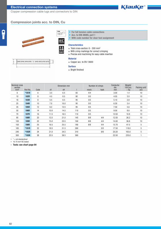
181rgrp
82
Electrical connection systems
Copper compression cable lugs and connectors to DIN
Compression joints acc. to DIN, Cu
For full tension cable connections
Acc. to DIN 48085, part 1
With code number for clear tool assignment
Characteristics
▪ Total cross-section: 6 - 300 mm²
▪ With crimp markings for correct crimping
▪ Precise end machining for easy cable insertion
Material
▪ Copper acc. to EN 13600
Surface
▪ Bright finished
Nominal cross section mm² Part No. Code
Dimension mm Number of crimps Conductor dia.mm
Weight/100 pcs.
~ kg Packing unit/
pcs d1 d4 l mech. hydr.
6 *181R 6 3.5 6.5 65 4/4 3.00 1.4 10
10 182R 8 4.5 8.5 80 5/5 4.05 3.0 10
16 183R 8 5.5 8.5 95 5/5 5.10 2.8 10
25 184R 10 7.0 10.0 95 5/5 6.30 3.4 10
35 185R 12 8.2 12.5 95 5/5 7.50 5.6 10
50 186R 14 10.0 14.5 110 5/5 9.00 8.6 10
70 187R 16 11.5 16.5 110 5/5 10.50 10.8 10
95 188R 20 13.5 21.0 145 8/8 4/4 12.50 26.2 10
120 189R 22 15.0 23.5 160 8/8 4/4 14.00 36.8 10
150 190R 25 16.5 25.5 180 8/8 4/4 15.70 47.5 5
185 *191R 32 18.5 31.5 260 5/5 17.50 118.0 5
240 *192R 34 21.0 34.5 310 6/6 20.20 163.0 5
300 *193R 38 23.5 38.5 360 22.50 235.0 1
* = not standardized
16-70 mm² IEC tested
Tools: see chart page 84
Klauke Hauptkatalog EN_DIN A5.indb 82 07.10.2014 12:16:40
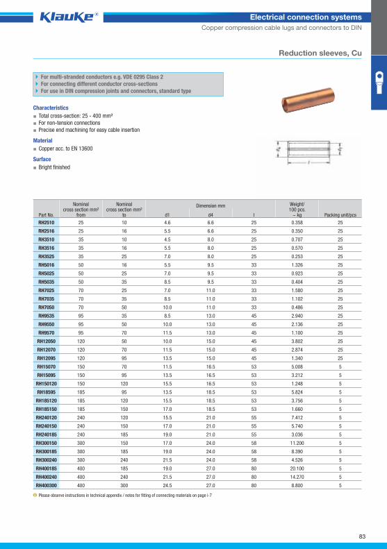
rh2510grp
83
Electrical connection systems
Copper compression cable lugs and connectors to DIN
Reduction sleeves, Cu
For multi-stranded conductors e.g. VDE 0295 Class 2
For connecting different conductor cross-sections
For use in DIN compression joints and connectors, standard type
Characteristics
▪ Total cross-section: 25 - 400 mm²
▪ For non-tension connections
▪ Precise end machining for easy cable insertion
Material
▪ Copper acc. to EN 13600
Surface
▪ Bright finished
Part No.
Nominalcross section mm²
from
Nominalcross section mm²
to
Dimension mm Weight/100 pcs.
~ kg Packing unit/pcs d1 d4 l
RH2510 25 10 4.6 6.6 25 0.358 25
RH2516 25 16 5.5 6.6 25 0.350 25
RH3510 35 10 4.5 8.0 25 0.707 25
RH3516 35 16 5.5 8.0 25 0.570 25
RH3525 35 25 7.0 8.0 25 0.253 25
RH5016 50 16 5.5 9.5 33 1.326 25
RH5025 50 25 7.0 9.5 33 0.923 25
RH5035 50 35 8.5 9.5 33 0.404 25
RH7025 70 25 7.0 11.0 33 1.580 25
RH7035 70 35 8.5 11.0 33 1.102 25
RH7050 70 50 10.0 11.0 33 0.486 25
RH9535 95 35 8.5 13.0 45 2.940 25
RH9550 95 50 10.0 13.0 45 2.136 25
RH9570 95 70 11.5 13.0 45 1.100 25
RH12050 120 50 10.0 15.0 45 3.802 25
RH12070 120 70 11.5 15.0 45 2.874 25
RH12095 120 95 13.5 15.0 45 1.340 25
RH15070 150 70 11.5 16.5 53 5.008 5
RH15095 150 95 13.5 16.5 53 3.212 5
RH150120 150 120 15.5 16.5 53 1.248 5
RH18595 185 95 13.5 18.5 53 5.824 5
RH185120 185 120 15.5 18.5 53 3.756 5
RH185150 185 150 17.0 18.5 53 1.660 5
RH240120 240 120 15.5 21.0 55 7.412 5
RH240150 240 150 17.0 21.0 55 5.740 5
RH240185 240 185 19.0 21.0 55 3.036 5
RH300150 300 150 17.0 24.0 58 11.200 5
RH300185 300 185 19.0 24.0 58 8.390 5
RH300240 300 240 21.5 24.0 58 4.526 5
RH400185 400 185 19.0 27.0 80 20.100 5
RH400240 400 240 21.5 27.0 80 14.270 5
RH400300 400 300 24.5 27.0 80 8.800 5
Please observe instructions in technical appendix / notes for fitting of connecting materials on page i-7
Klauke Hauptkatalog EN_DIN A5.indb 83 07.10.2014 12:16:40
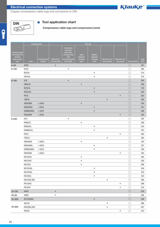
84
Electrical connection systems
Copper compression cable lugs and connectors to DIN
^WZT_PKS_DIN_einfach^ � Tool application chart
Compression cable lugs and compression joints
Crimping tools Tool type
Crimping rangecorresponds to
nominalcross-section
mm² ToolsCrimping head/
AdapterMechanical
crimping tools
mechanical,electrical,
pneumatic, crimping tools
with interchangeable
dies/heads
Handhydraulic crimping
tools
Batterypowered crimping
toolsHydraulic crim-ping systems
Hydraulic crim-ping heads Crimp profile
Page(Tool)
K05D • 2476-50
K354 • 260
EK354 • 314
EK354L • 316
6-120
K18 • 262
HK6018 • 286
EK505L • 318
EK5018L • 320
PK18 • 362
THK18 • 362
HK60UNV + UA18 • 354
EK60UNVL + UA18 • 357
EKM60UNVL + UA18 • 356
PK60UNV + UA18 • 355
6-185
K22 • 264
HK6022 • 288
EK6022L • 324
EKM6022L • 322
PK22 • 364
THK22 • 364
HK60UNV + UA22 • 354
EK60UNVL + UA22 • 357
EKM60UNVL + UA22 • 356
PK60UNV + UA22 • 355
HK12030 • 292
HK12042 • 294
HK120U • 296
EK12030L • 330
EK12042L • 332
EK120UL • 334
HK122EL380 • 390
PK12042 • 368
PK120U • 370
6-240
K06D • 25010-120
K08D • 24816-95
EK120UNVL • 35816-300
HK252 • 388
HK252EL380 • 391
PK252 • 372
16-625
Klauke Hauptkatalog EN_DIN A5.indb 84 07.10.2014 12:16:40
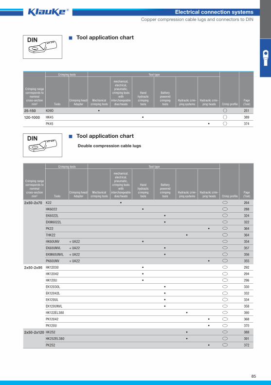
85
Electrical connection systems
Copper compression cable lugs and connectors to DIN
^WZT_PKS_DIN_doppelt^
� Tool application chart
Crimping tools Tool type
Crimping rangecorresponds to
nominalcross-section
mm² ToolsCrimping head/
AdapterMechanical
crimping tools
mechanical,electrical,
pneumatic, crimping tools
with interchangeable
dies/heads
Handhydraulic crimping
tools
Batterypowered crimping
toolsHydraulic crim-ping systems
Hydraulic crim-ping heads Crimp profile
Page(Tool)
K09D • 25125-150
HK45 • 389
PK45 • 374
120-1000
� Tool application chart
Double compression cable lugs
Crimping tools Tool type
Crimping rangecorresponds to
nominalcross-section
mm² ToolsCrimping head/
AdapterMechanical
crimping tools
mechanical,electrical,
pneumatic, crimping tools
with interchangeable
dies/heads
Handhydraulic crimping
tools
Batterypowered crimping
toolsHydraulic crim-ping systems
Hydraulic crim-ping heads Crimp profile
Page(Tool)
K22 • 264
HK6022 • 288
EK6022L • 324
EKM6022L • 322
PK22 • 364
THK22 • 364
HK60UNV + UA22 • 354
EK60UNVL + UA22 • 357
EKM60UNVL + UA22 • 356
PK60UNV + UA22 • 355
2x50-2x70
HK12030 • 292
HK12042 • 294
HK120U • 296
EK12030L • 330
EK12042L • 332
EK120UL • 334
EK120UNVL • 358
HK122EL380 • 390
PK12042 • 368
PK120U • 370
2x50-2x95
HK252 • 388
HK252EL380 • 391
PK252 • 372
2x50-2x120
Klauke Hauptkatalog EN_DIN A5.indb 85 07.10.2014 12:16:41
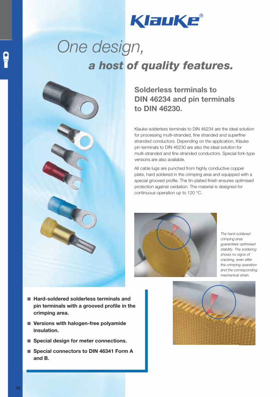
One design, a host of quality features.
Solderless terminals to
DIN 46234 and pin terminals
to DIN 46230.
◾ Hard-soldered solderless terminals and
pin terminals with a grooved profi le in the
crimping area.
◾ Versions with halogen-free polyamide
insulation.
◾ Special design for meter connections.
◾ Special connectors to DIN 46341 Form A
and B.
The hard-soldered
crimping area
guarantees optimised
stability. The soldering
shows no signs of
cracking, even after
the crimping operation
and the corresponding
mechanical strain.
Klauke solderless terminals to DIN 46234 are the ideal solution for processing multi-stranded, fi ne stranded and superfi ne stranded conductors. Depending on the application, Klauke pin terminals to DIN 46230 are also the ideal solution for multi-stranded and fi ne stranded conductors. Special fork-type versions are also available.
All cable lugs are punched from highly conductive copper plate, hard soldered in the crimping area and equipped with a special grooved profi le. The tin-plated fi nish ensures optimised protection against oxidation. The material is designed for continuous operation up to 120 °C.
86
Klauke Hauptkatalog EN_DIN A5.indb 86 07.10.2014 12:16:41
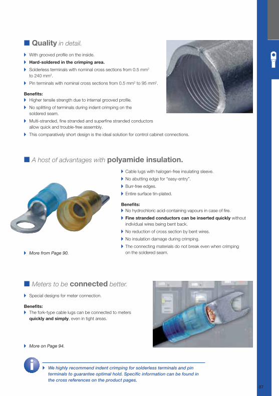
■ Quality in detail.
▸ With grooved profi le on the inside.
▸ Hard-soldered in the crimping area.
▸ Solderless terminals with nominal cross sections from 0.5 mm2
to 240 mm2.
▸ Pin terminals with nominal cross sections from 0.5 mm2 to 95 mm2.
Benefi ts: ▸ Higher tensile strength due to internal grooved profi le.
▸ No splitting of terminals during indent crimping on the
soldered seam.
▸ Multi-stranded, fi ne stranded and superfi ne stranded conductors
allow quick and trouble-free assembly.
▸ This comparatively short design is the ideal solution for control cabinet connections.
■ A host of advantages with polyamide insulation.
▸ Cable lugs with halogen-free insulating sleeve.
▸ No abutting edge for “easy-entry”.
▸ Burr-free edges.
▸ Entire surface tin-plated.
Benefi ts: ▸ No hydrochloric acid-containing vapours in case of fi re.
▸ Fine stranded conductors can be inserted quickly without
individual wires being bent back.
▸ No reduction of cross section by bent wires.
▸ No insulation damage during crimping.
▸ The connecting materials do not break even when crimping
on the soldered seam.
■ Meters to be connected better.
▸ Special designs for meter connection.
Benefi ts: ▸ The fork-type cable lugs can be connected to meters
quickly and simply, even in tight areas.
▸ More from Page 90.
▸ More on Page 94.
▸ We highly recommend indent crimping for solderless terminals and pin
terminals to guarantee optimal hold. Specifi c information can be found in
the cross references on the product pages.
87
Klauke Hauptkatalog EN_DIN A5.indb 87 07.10.2014 12:16:43
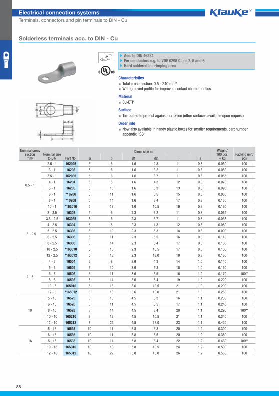
162025grp
88
Electrical connection systems
Terminals, connectors and pin terminals to DIN - Cu
Solderless terminals acc. to DIN - Cu
Acc. to DIN 46234
For conductors e.g. to VDE 0295 Class 2, 5 and 6
Hard soldered in crimping area
Characteristics
▪ Total cross-section: 0.5 - 240 mm²
▪ With grooved profile for improved contact characteristics
Material
▪ Cu-ETP
Surface
▪ Tin-plated to protect against corrosion (other surfaces available upon request)
Order info
▪ Now also available in handy plastic boxes for smaller requirements, part number
appendix "SB"
Nominal cross section mm²
Nominal sizeto DIN Part No.
Dimension mm Weight/100 pcs.
~ kg Packing unit/
pcs a b d1 d2 l s
0.5 - 1
2.5 - 1 162025 5 6 1.6 2.8 11 0.8 0.060 100
3 - 1 16203 5 6 1.6 3.2 11 0.8 0.060 100
3.5 - 1 162035 5 6 1.6 3.7 11 0.8 0.055 100
4 - 1 16204 5 8 1.6 4.3 12 0.8 0.070 100
5 - 1 16205 5 10 1.6 5.3 13 0.8 0.090 100
6 - 1 *16206 5 11 1.6 6.5 15 0.8 0.080 100
8 - 1 *16208 5 14 1.6 8.4 17 0.8 0.130 100
10 - 1 *162010 5 18 1.6 10.5 19 0.8 0.130 100
1.5 - 2.5
3 - 2.5 16303 5 6 2.3 3.2 11 0.8 0.065 100
3.5 - 2.5 163035 5 6 2.3 3.7 11 0.8 0.065 100
4 - 2.5 16304 5 8 2.3 4.3 12 0.8 0.080 100
5 - 2.5 16305 5 10 2.3 5.3 14 0.8 0.090 100
6 - 2.5 16306 5 11 2.3 6.5 16 0.8 0.110 100
8 - 2.5 16308 5 14 2.3 8.4 17 0.8 0.130 100
10 - 2.5 *163010 5 15 2.3 10.5 17 0.8 0.160 100
12 - 2.5 *163012 5 18 2.3 13.0 19 0.8 0.160 100
4 - 6
4 - 6 16504 6 8 3.6 4.3 14 1.0 0.140 100
5 - 6 16505 6 10 3.6 5.3 15 1.0 0.160 100
6 - 6 16506 6 11 3.6 6.5 16 1.0 0.170 100**
8 - 6 16508 6 14 3.6 8.4 19 1.0 0.220 100
10 - 6 165010 6 18 3.6 10.5 21 1.0 0.290 100
12 - 6 *165012 6 18 3.6 13.0 21 1.0 0.280 100
10
5 - 10 16525 8 10 4.5 5.3 16 1.1 0.230 100
6 - 10 16526 8 11 4.5 6.5 17 1.1 0.240 100
8 - 10 16528 8 14 4.5 8.4 20 1.1 0.290 100**
10 - 10 165210 8 18 4.5 10.5 21 1.1 0.340 100
12 - 10 165212 8 22 4.5 13.0 23 1.1 0.420 100
16
5 - 16 16535 10 11 5.8 5.3 20 1.2 0.390 100
6 - 16 16536 10 11 5.8 6.5 20 1.2 0.380 100
8 - 16 16538 10 14 5.8 8.4 22 1.2 0.430 100**
10 - 16 165310 10 18 5.8 10.5 24 1.2 0.500 100
12 - 16 165312 10 22 5.8 13.0 26 1.2 0.580 100
Klauke Hauptkatalog EN_DIN A5.indb 88 07.10.2014 12:16:43
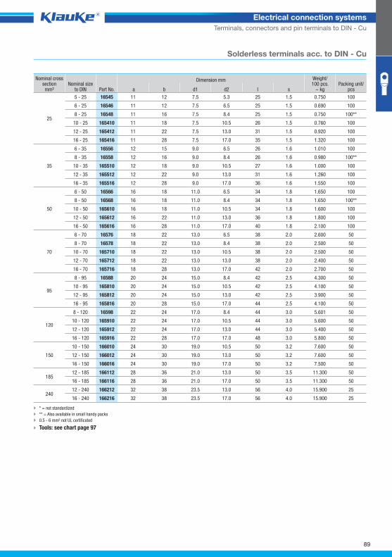
89
Electrical connection systems
Terminals, connectors and pin terminals to DIN - Cu
Solderless terminals acc. to DIN - Cu
Nominal cross section mm²
Nominal sizeto DIN Part No.
Dimension mm Weight/100 pcs.
~ kg Packing unit/
pcs a b d1 d2 l s
25
5 - 25 16545 11 12 7.5 5.3 25 1.5 0.750 100
6 - 25 16546 11 12 7.5 6.5 25 1.5 0.690 100
8 - 25 16548 11 16 7.5 8.4 25 1.5 0.750 100**
10 - 25 165410 11 18 7.5 10.5 26 1.5 0.760 100
12 - 25 165412 11 22 7.5 13.0 31 1.5 0.920 100
16 - 25 165416 11 28 7.5 17.0 35 1.5 1.320 100
35
6 - 35 16556 12 15 9.0 6.5 26 1.6 1.010 100
8 - 35 16558 12 16 9.0 8.4 26 1.6 0.980 100**
10 - 35 165510 12 18 9.0 10.5 27 1.6 1.000 100
12 - 35 165512 12 22 9.0 13.0 31 1.6 1.260 100
16 - 35 165516 12 28 9.0 17.0 36 1.6 1.550 100
50
6 - 50 16566 16 18 11.0 6.5 34 1.8 1.650 100
8 - 50 16568 16 18 11.0 8.4 34 1.8 1.650 100**
10 - 50 165610 16 18 11.0 10.5 34 1.8 1.600 100
12 - 50 165612 16 22 11.0 13.0 36 1.8 1.800 100
16 - 50 165616 16 28 11.0 17.0 40 1.8 2.100 100
70
6 - 70 16576 18 22 13.0 6.5 38 2.0 2.600 50
8 - 70 16578 18 22 13.0 8.4 38 2.0 2.500 50
10 - 70 165710 18 22 13.0 10.5 38 2.0 2.500 50
12 - 70 165712 18 22 13.0 13.0 38 2.0 2.400 50
16 - 70 165716 18 28 13.0 17.0 42 2.0 2.700 50
95
8 - 95 16588 20 24 15.0 8.4 42 2.5 4.300 50
10 - 95 165810 20 24 15.0 10.5 42 2.5 4.100 50
12 - 95 165812 20 24 15.0 13.0 42 2.5 3.900 50
16 - 95 165816 20 28 15.0 17.0 44 2.5 4.100 50
120
8 - 120 16598 22 24 17.0 8.4 44 3.0 5.601 50
10 - 120 165910 22 24 17.0 10.5 44 3.0 5.600 50
12 - 120 165912 22 24 17.0 13.0 44 3.0 5.400 50
16 - 120 165916 22 28 17.0 17.0 48 3.0 5.800 50
150
10 - 150 166010 24 30 19.0 10.5 50 3.2 7.600 50
12 - 150 166012 24 30 19.0 13.0 50 3.2 7.600 50
16 - 150 166016 24 30 19.0 17.0 50 3.2 7.500 50
185 12 - 185 166112 28 36 21.0 13.0 50 3.5 11.300 50
16 - 185 166116 28 36 21.0 17.0 50 3.5 11.300 50
240 12 - 240 166212 32 38 23.5 13.0 56 4.0 15.900 25
16 - 240 166216 32 38 23.5 17.0 56 4.0 15.900 25
* = not standardized
** = Also available in small handy packs
0.5 - 6 mm² not UL certificated
Tools: see chart page 97
Klauke Hauptkatalog EN_DIN A5.indb 89 07.10.2014 12:16:44
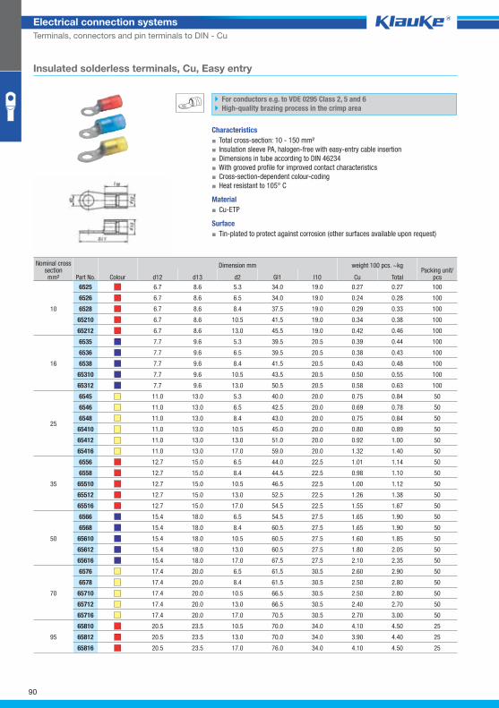
6525grp
90
Electrical connection systems
Terminals, connectors and pin terminals to DIN - Cu
Insulated solderless terminals, Cu, Easy entry
For conductors e.g. to VDE 0295 Class 2, 5 and 6
High-quality brazing process in the crimp area
Characteristics
▪ Total cross-section: 10 - 150 mm²
▪ Insulation sleeve PA, halogen-free with easy-entry cable insertion
▪ Dimensions in tube according to DIN 46234
▪ With grooved profile for improved contact characteristics
▪ Cross-section-dependent colour-coding
▪ Heat resistant to 105° C
Material
▪ Cu-ETP
Surface
▪ Tin-plated to protect against corrosion (other surfaces available upon request)
Nominal cross section mm² Part No. Colour
Dimension mm weight 100 pcs. ~kg Packing unit/
pcs d12 d13 d2 Gl1 l10 Cu Total
10
6525 6.7 8.6 5.3 34.0 19.0 0.27 0.27 100
6526 6.7 8.6 6.5 34.0 19.0 0.24 0.28 100
6528 6.7 8.6 8.4 37.5 19.0 0.29 0.33 100
65210 6.7 8.6 10.5 41.5 19.0 0.34 0.38 100
65212 6.7 8.6 13.0 45.5 19.0 0.42 0.46 100
16
6535 7.7 9.6 5.3 39.5 20.5 0.39 0.44 100
6536 7.7 9.6 6.5 39.5 20.5 0.38 0.43 100
6538 7.7 9.6 8.4 41.5 20.5 0.43 0.48 100
65310 7.7 9.6 10.5 43.5 20.5 0.50 0.55 100
65312 7.7 9.6 13.0 50.5 20.5 0.58 0.63 100
25
6545 11.0 13.0 5.3 40.0 20.0 0.75 0.84 50
6546 11.0 13.0 6.5 42.5 20.0 0.69 0.78 50
6548 11.0 13.0 8.4 43.0 20.0 0.75 0.84 50
65410 11.0 13.0 10.5 45.0 20.0 0.80 0.89 50
65412 11.0 13.0 13.0 51.0 20.0 0.92 1.00 50
65416 11.0 13.0 17.0 59.0 20.0 1.32 1.40 50
35
6556 12.7 15.0 6.5 44.0 22.5 1.01 1.14 50
6558 12.7 15.0 8.4 44.5 22.5 0.98 1.10 50
65510 12.7 15.0 10.5 46.5 22.5 1.00 1.12 50
65512 12.7 15.0 13.0 52.5 22.5 1.26 1.38 50
65516 12.7 15.0 17.0 54.5 22.5 1.55 1.67 50
50
6566 15.4 18.0 6.5 54.5 27.5 1.65 1.90 50
6568 15.4 18.0 8.4 60.5 27.5 1.65 1.90 50
65610 15.4 18.0 10.5 60.5 27.5 1.60 1.85 50
65612 15.4 18.0 13.0 60.5 27.5 1.80 2.05 50
65616 15.4 18.0 17.0 67.5 27.5 2.10 2.35 50
70
6576 17.4 20.0 6.5 61.5 30.5 2.60 2.90 50
6578 17.4 20.0 8.4 61.5 30.5 2.50 2.80 50
65710 17.4 20.0 10.5 66.5 30.5 2.50 2.80 50
65712 17.4 20.0 13.0 66.5 30.5 2.40 2.70 50
65716 17.4 20.0 17.0 70.5 30.5 2.70 3.00 50
95
65810 20.5 23.5 10.5 70.0 34.0 4.10 4.50 25
65812 20.5 23.5 13.0 70.0 34.0 3.90 4.40 25
65816 20.5 23.5 17.0 76.0 34.0 4.10 4.50 25
Klauke Hauptkatalog EN_DIN A5.indb 90 07.10.2014 12:16:44
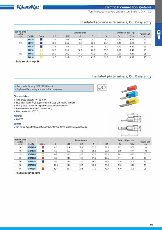
st1716isgrp
91
Electrical connection systems
Terminals, connectors and pin terminals to DIN - Cu
Insulated solderless terminals, Cu, Easy entry
Nominal cross section mm² Part No. Colour
Dimension mm weight 100 pcs. ~kg Packing unit/
pcs d12 d13 d2 Gl1 l10 Cu Total
120
65910 23.5 26.7 10.5 79.0 36.0 5.60 6.10 25
65912 23.5 26.7 13.0 82.0 36.0 5.40 5.90 25
65916 23.5 26.7 17.0 90.0 36.0 5.80 6.30 25
150
66010 26.0 29.2 10.5 80.0 39.0 7.60 8.40 25
66012 26.0 29.2 13.0 83.0 39.0 7.60 8.40 25
66016 26.0 29.2 17.0 83.0 39.0 7.50 8.30 25
Tools: see chart page 99
Insulated pin terminals, Cu, Easy entry
For conductors e.g. VDE 0295 Class 2
High-quality brazing process in the crimp area
Characteristics
▪ Total cross-section: 10 - 95 mm²
▪ Insulation sleeve PA, halogen-free with easy-entry cable insertion
▪ With grooved profile for improved contact characteristics
▪ Cross-section-dependent colour-coding
▪ Heat resistant to 105° C
Material
▪ Cu-ETP
Surface
▪ Tin-plated to protect against corrosion (other surfaces available upon request)
Nominal cross section mm² Part No. Colour
Dimension mm Weight 100 pcs. ~kg Packing unit/
pcs b d12 d13 Gl1 l10 Cu Total
10 ST1716IS 4.3 7.4 9.4 33.0 19.0 0.27 0.31 100
16 ST1717IS 5.5 8.6 10.6 38.0 20.0 0.39 0.44 100
25 ST1718IS 6.8 12.5 14.5 43.5 23.5 0.63 0.73 50
35 ST1719IS 8.0 14.0 16.4 51.5 27.5 1.17 1.34 50
50 ST1720IS 9.5 15.5 18.0 59.0 33.0 1.79 2.10 50
70 ST1721IS 11.0 18.0 20.5 69.0 38.0 2.92 3.20 50
95 ST1722IS 12.5 20.7 23.5 71.0 40.0 4.30 4.70 25
Tools: see chart page 99
Klauke Hauptkatalog EN_DIN A5.indb 91 07.10.2014 12:16:45
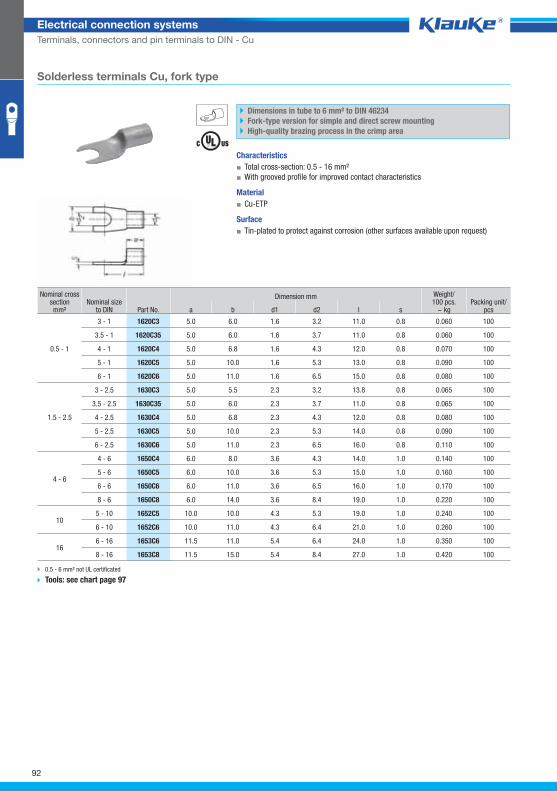
1620c3grp
92
Electrical connection systems
Terminals, connectors and pin terminals to DIN - Cu
Solderless terminals Cu, fork type
Dimensions in tube to 6 mm² to DIN 46234
Fork-type version for simple and direct screw mounting
High-quality brazing process in the crimp area
Characteristics
▪ Total cross-section: 0.5 - 16 mm²
▪ With grooved profile for improved contact characteristics
Material
▪ Cu-ETP
Surface
▪ Tin-plated to protect against corrosion (other surfaces available upon request)
Nominal cross section mm²
Nominal sizeto DIN Part No.
Dimension mm Weight/100 pcs.
~ kg Packing unit/
pcs a b d1 d2 l s
0.5 - 1
3 - 1 1620C3 5.0 6.0 1.6 3.2 11.0 0.8 0.060 100
3.5 - 1 1620C35 5.0 6.0 1.6 3.7 11.0 0.8 0.060 100
4 - 1 1620C4 5.0 6.8 1.6 4.3 12.0 0.8 0.070 100
5 - 1 1620C5 5.0 10.0 1.6 5.3 13.0 0.8 0.090 100
6 - 1 1620C6 5.0 11.0 1.6 6.5 15.0 0.8 0.080 100
1.5 - 2.5
3 - 2.5 1630C3 5.0 5.5 2.3 3.2 13.8 0.8 0.065 100
3.5 - 2.5 1630C35 5.0 6.0 2.3 3.7 11.0 0.8 0.065 100
4 - 2.5 1630C4 5.0 6.8 2.3 4.3 12.0 0.8 0.080 100
5 - 2.5 1630C5 5.0 10.0 2.3 5.3 14.0 0.8 0.090 100
6 - 2.5 1630C6 5.0 11.0 2.3 6.5 16.0 0.8 0.110 100
4 - 6
4 - 6 1650C4 6.0 8.0 3.6 4.3 14.0 1.0 0.140 100
5 - 6 1650C5 6.0 10.0 3.6 5.3 15.0 1.0 0.160 100
6 - 6 1650C6 6.0 11.0 3.6 6.5 16.0 1.0 0.170 100
8 - 6 1650C8 6.0 14.0 3.6 8.4 19.0 1.0 0.220 100
10 5 - 10 1652C5 10.0 10.0 4.3 5.3 19.0 1.0 0.240 100
6 - 10 1652C6 10.0 11.0 4.3 6.4 21.0 1.0 0.260 100
16 6 - 16 1653C6 11.5 11.0 5.4 6.4 24.0 1.0 0.350 100
8 - 16 1653C8 11.5 15.0 5.4 8.4 27.0 1.0 0.420 100
0.5 - 6 mm² not UL certificated
Tools: see chart page 97
Klauke Hauptkatalog EN_DIN A5.indb 92 07.10.2014 12:16:45
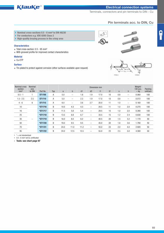
st1705grp
93
Electrical connection systems
Terminals, connectors and pin terminals to DIN - Cu
Pin terminals acc. to DIN, Cu
Nominal cross-sections 0.5 - 6 mm² to DIN 46230
For conductors e.g. VDE 0295 Class 2
High-quality brazing process in the crimp area
Characteristics
▪ Total cross-section: 0.5 - 95 mm²
▪ With grooved profile for improved contact characteristics
Material
▪ Cu-ETP
Surface
▪ Tin-plated to protect against corrosion (other surfaces available upon request)
Nominal cross section mm²
Nominal size
to DIN Part No. Typ
Dimension mm Weight/100 pcs.
~ kg Packing unit/pcs a b d1 d2 l1 l2 s h
0.5 - 1 1 ST1705 A 5.0 -- 1.8 1.9 17.0 10 0.8 -- 0.060 100
1.5 - 2.5 2.5 ST1710 A 5.0 -- 2.3 1.9 17.0 10 0.8 -- 0.072 100
4 - 6 6 ST1715 A 6.0 -- 3.6 2.7 20.0 11 1.0 -- 0.160 100
10
--
*ST1716 B 10.0 4.3 4.3 -- 24.5 11 1.0 2.0 0.270 100
16 *ST1717 B 11.5 5.8 5.4 -- 29.5 15 1.0 2.0 0.390 100
25 *ST1718 B 13.5 6.8 6.7 -- 33.5 15 1.2 2.4 0.630 100
35 *ST1719 B 16.0 8.0 8.2 -- 40.5 20 1.5 3.2 1.170 50
50 *ST1720 B 19.0 9.5 9.5 -- 45.0 20 1.8 3.6 1.790 50
70 *ST1721 B 24.0 11.0 11.2 -- 55.0 23 2.0 4.0 2.920 50
95 *ST1722 B 24.0 12.5 13.5 -- 55.0 23 2.5 5.0 4.300 50
* = not standardized
0.5 - 6 mm² not UL certificated
Tools: see chart page 97
Klauke Hauptkatalog EN_DIN A5.indb 93 07.10.2014 12:16:45
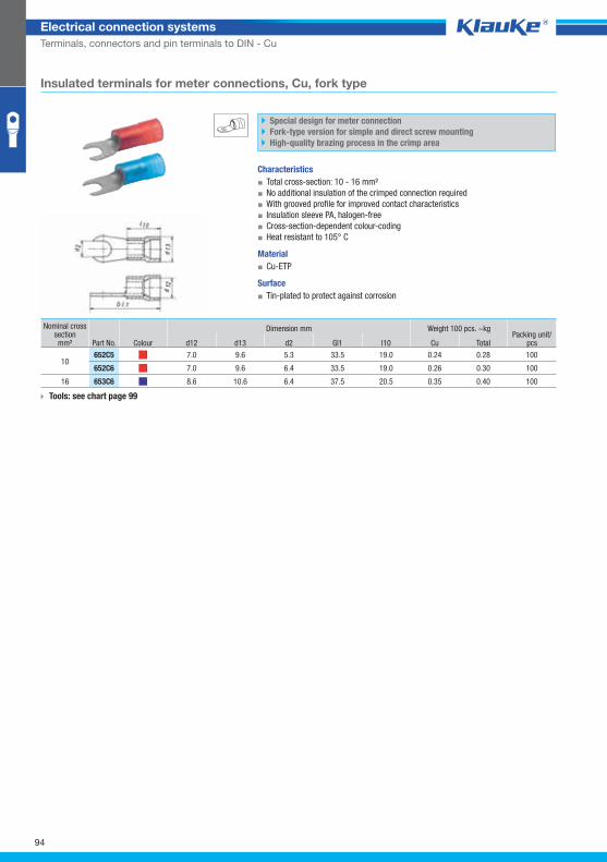
652c5grp
94
Electrical connection systems
Terminals, connectors and pin terminals to DIN - Cu
Insulated terminals for meter connections, Cu, fork type
Special design for meter connection
Fork-type version for simple and direct screw mounting
High-quality brazing process in the crimp area
Characteristics
▪ Total cross-section: 10 - 16 mm²
▪ No additional insulation of the crimped connection required
▪ With grooved profile for improved contact characteristics
▪ Insulation sleeve PA, halogen-free
▪ Cross-section-dependent colour-coding
▪ Heat resistant to 105° C
Material
▪ Cu-ETP
Surface
▪ Tin-plated to protect against corrosion
Nominal cross section mm² Part No. Colour
Dimension mm Weight 100 pcs. ~kg Packing unit/
pcs d12 d13 d2 Gl1 l10 Cu Total
10 652C5 7.0 9.6 5.3 33.5 19.0 0.24 0.28 100
652C6 7.0 9.6 6.4 33.5 19.0 0.26 0.30 100
16 653C6 8.6 10.6 6.4 37.5 20.5 0.35 0.40 100
Tools: see chart page 99
Klauke Hauptkatalog EN_DIN A5.indb 94 07.10.2014 12:16:46
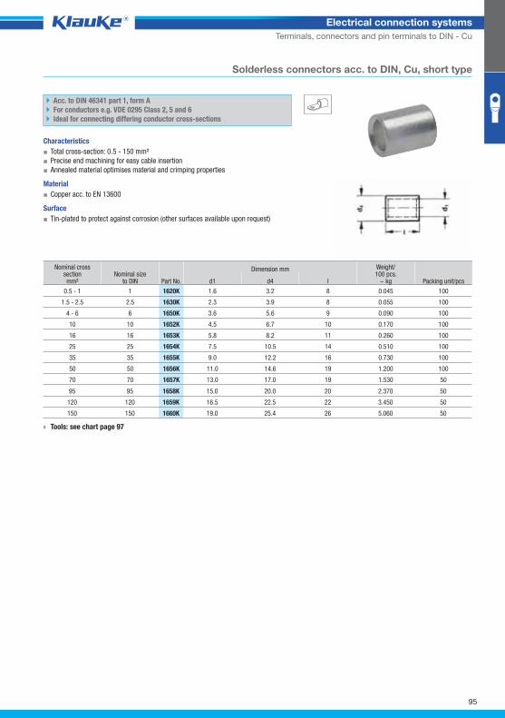
1620kgrp
95
Electrical connection systems
Terminals, connectors and pin terminals to DIN - Cu
Solderless connectors acc. to DIN, Cu, short type
Acc. to DIN 46341 part 1, form A
For conductors e.g. VDE 0295 Class 2, 5 and 6
Ideal for connecting differing conductor cross-sections
Characteristics
▪ Total cross-section: 0.5 - 150 mm²
▪ Precise end machining for easy cable insertion
▪ Annealed material optimises material and crimping properties
Material
▪ Copper acc. to EN 13600
Surface
▪ Tin-plated to protect against corrosion (other surfaces available upon request)
Nominal cross section mm²
Nominal sizeto DIN Part No.
Dimension mm Weight/100 pcs.
~ kg Packing unit/pcs d1 d4 l
0.5 - 1 1 1620K 1.6 3.2 8 0.045 100
1.5 - 2.5 2.5 1630K 2.3 3.9 8 0.055 100
4 - 6 6 1650K 3.6 5.6 9 0.090 100
10 10 1652K 4.5 6.7 10 0.170 100
16 16 1653K 5.8 8.2 11 0.260 100
25 25 1654K 7.5 10.5 14 0.510 100
35 35 1655K 9.0 12.2 16 0.730 100
50 50 1656K 11.0 14.6 19 1.200 100
70 70 1657K 13.0 17.0 19 1.530 50
95 95 1658K 15.0 20.0 20 2.370 50
120 120 1659K 16.5 22.5 22 3.450 50
150 150 1660K 19.0 25.4 26 5.060 50
Tools: see chart page 97
Klauke Hauptkatalog EN_DIN A5.indb 95 07.10.2014 12:16:46
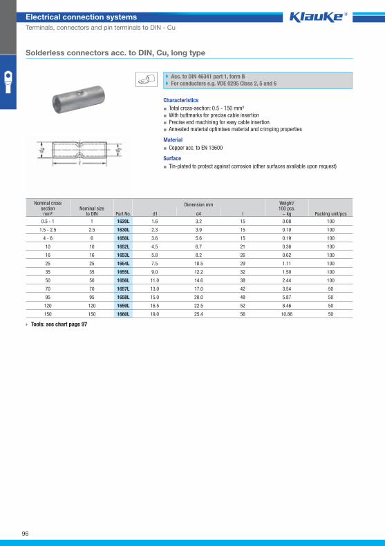
1620lgrp
96
Electrical connection systems
Terminals, connectors and pin terminals to DIN - Cu
Solderless connectors acc. to DIN, Cu, long type
Acc. to DIN 46341 part 1, form B
For conductors e.g. VDE 0295 Class 2, 5 and 6
Characteristics
▪ Total cross-section: 0.5 - 150 mm²
▪ With buttmarks for precise cable insertion
▪ Precise end machining for easy cable insertion
▪ Annealed material optimises material and crimping properties
Material
▪ Copper acc. to EN 13600
Surface
▪ Tin-plated to protect against corrosion (other surfaces available upon request)
Nominal cross section mm²
Nominal sizeto DIN Part No.
Dimension mm Weight/100 pcs.
~ kg Packing unit/pcs d1 d4 l
0.5 - 1 1 1620L 1.6 3.2 15 0.08 100
1.5 - 2.5 2.5 1630L 2.3 3.9 15 0.10 100
4 - 6 6 1650L 3.6 5.6 15 0.19 100
10 10 1652L 4.5 6.7 21 0.36 100
16 16 1653L 5.8 8.2 26 0.62 100
25 25 1654L 7.5 10.5 29 1.11 100
35 35 1655L 9.0 12.2 32 1.50 100
50 50 1656L 11.0 14.6 38 2.44 100
70 70 1657L 13.0 17.0 42 3.54 50
95 95 1658L 15.0 20.0 48 5.87 50
120 120 1659L 16.5 22.5 52 8.46 50
150 150 1660L 19.0 25.4 56 10.86 50
Tools: see chart page 97
Klauke Hauptkatalog EN_DIN A5.indb 96 07.10.2014 12:16:46
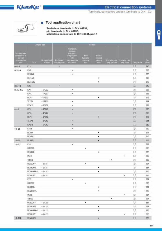
97
Electrical connection systems
Terminals, connectors and pin terminals to DIN - Cu
^WZT_QKS_DIN^
EK505L • 318
� Tool application chart
Solderless terminals to DIN 46234,pin terminals to DIN 46230,solderless connectors to DIN 46341, part 1
Crimping tools Tool type
Crimping rangecorresponds to
nominalcross-section
mm² ToolsCrimping head/
AdapterMechanical
crimping tools
mechanical,electrical,
pneumatic, crimping tools
with interchangeable
dies/heads
Handhydraulic crimping
tools
Batterypowered crimping
toolsHydraulic crim-ping systems
Hydraulic crim-ping heads Crimp profile
Page(Tool)
K13 • 2400.5-6
K50 • 259
EK50ML • 278
EK1550 • 308
EK1550G • 310
0.5-10
K25 • 2420.5-16
KP1 +KP232 • 256
KP1L +KP232 • 256
EKP1 +KP232 • 312
TEKP1 +KP232 • 281
KPM15 +KP232 • 282
0.75-2.5
KP1 +KP242 • 256
KP1L +KP242 • 256
EKP1 +KP242 • 312
TEKP1 +KP242 • 281
KPM15 +KP242 • 282
4-10
K354 • 260
EK354 • 314
EK354L • 316
10-35
10-50
K18 • 262
HK6018 • 286
EK5018L • 320
PK18 • 362
THK18 • 362
HK60UNV + UA18 • 354
EK60UNVL + UA18 • 357
EKM60UNVL + UA18 • 356
PK60UNV + UA18 • 355
K22 • 264
HK6022 • 288
EK6022L • 324
EKM6022L • 322
PK22 • 364
THK22 • 364
10-70
HK60UNV + UA22 • 354
EK60UNVL + UA22 • 357
EKM60UNVL + UA22 • 356
PK60UNV + UA22 • 355
EKM60IDL • 32810-240
Klauke Hauptkatalog EN_DIN A5.indb 97 07.10.2014 12:16:47
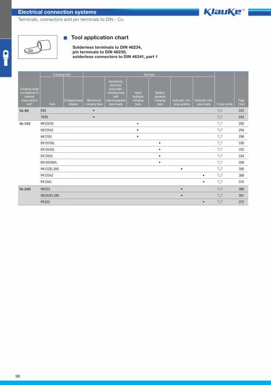
98
Electrical connection systems
Terminals, connectors and pin terminals to DIN - Cu
� Tool application chart
Solderless terminals to DIN 46234,pin terminals to DIN 46230,solderless connectors to DIN 46341, part 1
Crimping tools Tool type
Crimping rangecorresponds to
nominalcross-section
mm² ToolsCrimping head/
AdapterMechanical
crimping tools
mechanical,electrical,
pneumatic, crimping tools
with interchangeable
dies/heads
Handhydraulic crimping
tools
Batterypowered crimping
toolsHydraulic crim-ping systems
Hydraulic crim-ping heads Crimp profile
Page(Tool)
HK12030 • 292
HK12042 • 294
HK120U • 296
EK12030L • 330
EK12042L • 332
EK120UL • 334
EK120UNVL • 358
HK122EL380 • 390
PK12042 • 368
PK120U • 370
16-150
K95 • 242
TK95 • 243
16-95
HK252 • 388
HK252EL380 • 391
PK252 • 372
16-240
Klauke Hauptkatalog EN_DIN A5.indb 98 07.10.2014 12:16:47
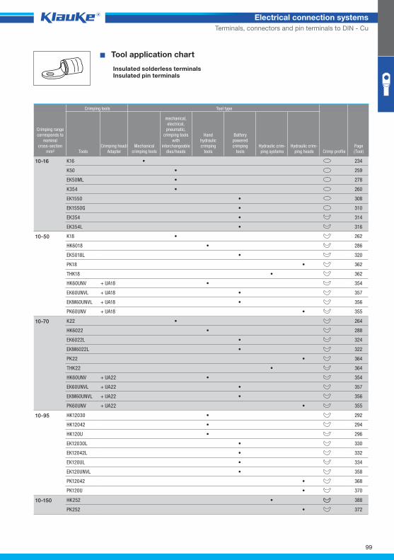
99
Electrical connection systems
Terminals, connectors and pin terminals to DIN - Cu
^WZT_QKS_isoliert^ � Tool application chart
Insulated solderless terminalsInsulated pin terminals
Crimping tools Tool type
Crimping rangecorresponds to
nominalcross-section
mm² ToolsCrimping head/
AdapterMechanical
crimping tools
mechanical,electrical,
pneumatic, crimping tools
with interchangeable
dies/heads
Handhydraulic crimping
tools
Batterypowered crimping
toolsHydraulic crim-ping systems
Hydraulic crim-ping heads Crimp profile
Page(Tool)
K16 • 234
K50 • 259
EK50ML • 278
K354 • 260
EK1550 • 308
EK1550G • 310
EK354 • 314
EK354L • 316
10-16
K18 • 262
HK6018 • 286
EK5018L • 320
PK18 • 362
THK18 • 362
HK60UNV + UA18 • 354
EK60UNVL + UA18 • 357
EKM60UNVL + UA18 • 356
PK60UNV + UA18 • 355
10-50
K22 • 264
HK6022 • 288
EK6022L • 324
EKM6022L • 322
PK22 • 364
THK22 • 364
HK60UNV + UA22 • 354
EK60UNVL + UA22 • 357
EKM60UNVL + UA22 • 356
PK60UNV + UA22 • 355
10-70
HK12030 • 292
HK12042 • 294
HK120U • 296
EK12030L • 330
EK12042L • 332
EK120UL • 334
EK120UNVL • 358
PK12042 • 368
PK120U • 370
10-95
HK252 • 388
PK252 • 372
10-150
Klauke Hauptkatalog EN_DIN A5.indb 99 07.10.2014 12:16:47
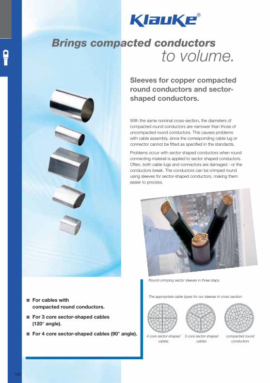
Brings compacted conductors to volume.
With the same nominal cross-section, the diameters of compacted round conductors are narrower than those of uncompacted round conductors. This causes problems with cable assembly, since the corresponding cable lug or connector cannot be fi tted as specifi ed in the standards.
Problems occur with sector shaped conductors when round connecting material is applied to sector shaped conductors. Often, both cable lugs and connectors are damaged - or the conductors break. The conductors can be crimped round using sleeves for sector-shaped conductors, making them easier to process.
Sleeves for copper compacted
round conductors and sector-
shaped conductors.
◾ For cables with
compacted round conductors.
◾ For 3 core sector-shaped cables
(120° angle).
◾ For 4 core sector-shaped cables (90° angle).
Round-crimping sector sleeves in three steps.
The appropriate cable types for our sleeves in cross section:
4 core sector-shaped
cables
compacted round
conductors
3 core sector-shaped
cables
100
Klauke Hauptkatalog EN_DIN A5.indb 100 07.10.2014 12:16:48
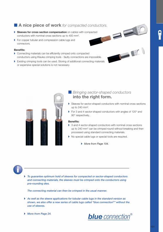
■ Bringing sector-shaped conductors
into the right form.
▸ Sleeves for sector-shaped conductors with nominal cross sections
up to 240 mm2.
▸ For 3 and 4 sector-shaped conductors with angles of 120° and
90° respectively.
Benefi ts: ▸ 3 and 4 sector-shaped conductors with nominal cross sections
up to 240 mm2 can be crimped round without breaking and then
processed using standard connecting materials.
▸ No special cable lugs or special tools are required.
▸ More from Page 104.
▸ To guarantee optimum hold of sleeves for compacted or sector-shaped conductors
and connecting materials, the sleeves must be crimped onto the conductors using
pre-rounding dies.
The connecting material can then be crimped in the usual manner.
▸ As well as the sleeve applications for tubular cable lugs in the standard version as
shown, we also offer a new series of cable lugs called “blue connection®” without the
use of sleeves.
▸ More from Page 24.
■ A nice piece of work for compacted conductors. ▸ Sleeves for cross section compensation on cables with compacted
conductors with nominal cross sections up to 400 mm2.
▸ For copper tubular and compression cable lugs and
connectors.
Benefi ts: ▸ Connecting materials can be effi ciently crimped onto compacted
conductors using Klauke crimping tools - faulty connections are impossible.
▸ Existing crimping tools can be used. Storing of additional connecting materials
or expensive special solutions is not necessary.
101
Klauke Hauptkatalog EN_DIN A5.indb 101 07.10.2014 12:16:49
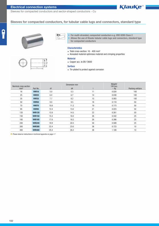
vhr16grp
102
Electrical connection systems
Sleeves for compacted conductors and sector-shaped conductors - Cu
Sleeves for compacted conductors, for tubular cable lugs and connectors, standard type
For multi-stranded, compacted conductors e.g. VDE 0295 Class 2
Allows the use of Klauke tubular cable lugs and connectors, standard type
for compacted conductors
Characteristics
▪ Total cross-section: 16 - 400 mm²
▪ Annealed material optimises material and crimping properties
Material
▪ Copper acc. to EN 13600
Surface
▪ Tin-plated to protect against corrosion
Nominal cross section mm² Part No.
Dimension mm Weight/100 pcs.
~ kg Packing unit/pcs d1 d4 l
16 VHR16 5.0 5.3 11 0.024 100
25 VHR25 6.4 6.7 14 0.038 100
35 VHR35 7.7 8.2 15 0.083 100
50 VHR50 9.0 9.5 18 0.118 50
70 VHR70 10.6 11.2 19 0.173 50
95 VHR95 12.4 13.0 21 0.223 50
120 VHR120 13.9 14.5 22 0.261 50
150 VHR150 15.4 16.0 26 0.342 25
185 VHR185 17.6 18.2 26 0.396 25
240 VHR240 19.9 20.5 30 0.508 25
300 VHR300 22.4 23.0 38 0.723 10
400 VHR400 25.4 26.2 38 1.108 10
Please observe instructions in technical appendix on page i-7
Klauke Hauptkatalog EN_DIN A5.indb 102 07.10.2014 12:16:50
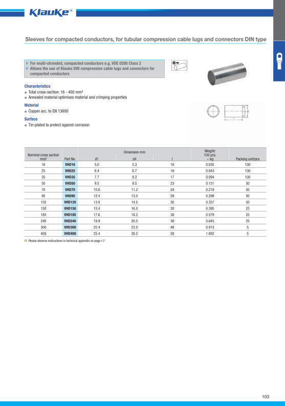
vhd16grp
103
Sleeves for compacted conductors, for tubular compression cable lugs and connectors DIN type
For multi-stranded, compacted conductors e.g. VDE 0295 Class 2
Allows the use of Klauke DIN compression cable lugs and connectors for
compacted conductors
Characteristics
▪ Total cross-section: 16 - 400 mm²
▪ Annealed material optimises material and crimping properties
Material
▪ Copper acc. to EN 13600
Surface
▪ Tin-plated to protect against corrosion
Nominal cross section mm² Part No.
Dimension mm Weight/100 pcs.
~ kg Packing unit/pcs d1 d4 l
16 VHD16 5.0 5.3 16 0.035 100
25 VHD25 6.4 6.7 16 0.043 100
35 VHD35 7.7 8.2 17 0.094 100
50 VHD50 9.0 9.5 23 0.151 50
70 VHD70 10.6 11.2 24 0.219 50
95 VHD95 12.4 13.0 28 0.298 50
120 VHD120 13.9 14.5 30 0.357 50
150 VHD150 15.4 16.0 30 0.395 25
185 VHD185 17.6 18.2 38 0.579 25
240 VHD240 19.9 20.5 38 0.645 25
300 VHD300 22.4 23.0 48 0.913 5
400 VHD400 25.4 26.2 58 1.692 5
Please observe instructions in technical appendix on page i-7
Klauke Hauptkatalog EN_DIN A5.indb 103 07.10.2014 12:16:50
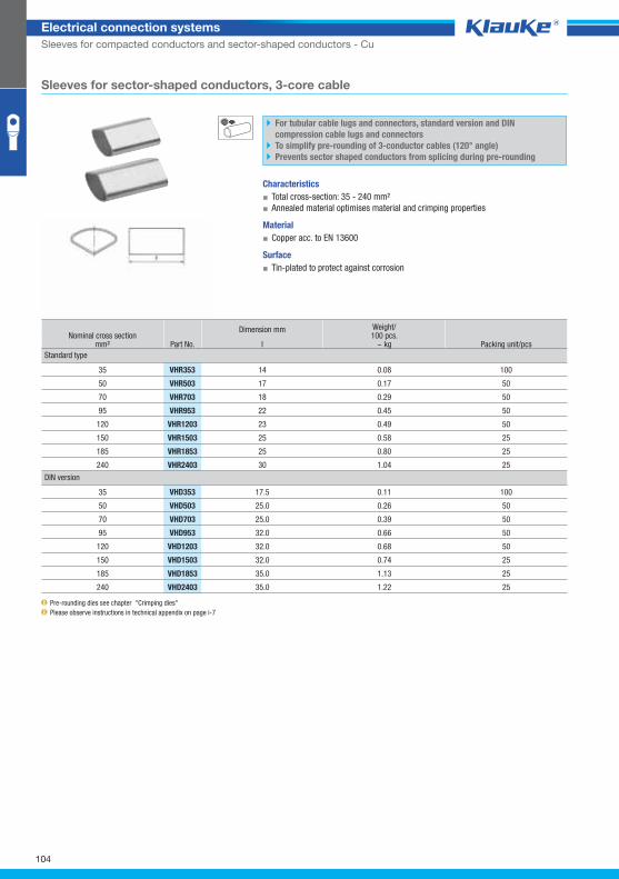
VHR353_GRP01
104
Electrical connection systems
Sleeves for compacted conductors and sector-shaped conductors - Cu
Sleeves for sector-shaped conductors, 3-core cable
For tubular cable lugs and connectors, standard version and DIN
compression cable lugs and connectors
To simplify pre-rounding of 3-conductor cables (120° angle)
Prevents sector shaped conductors from splicing during pre-rounding
Characteristics
▪ Total cross-section: 35 - 240 mm²
▪ Annealed material optimises material and crimping properties
Material
▪ Copper acc. to EN 13600
Surface
▪ Tin-plated to protect against corrosion
Nominal cross section mm² Part No.
Dimension mm Weight/100 pcs.
~ kg Packing unit/pcs l
Standard type
35 VHR353 14 0.08 100
50 VHR503 17 0.17 50
70 VHR703 18 0.29 50
95 VHR953 22 0.45 50
120 VHR1203 23 0.49 50
150 VHR1503 25 0.58 25
185 VHR1853 25 0.80 25
240 VHR2403 30 1.04 25
DIN version
35 VHD353 17.5 0.11 100
50 VHD503 25.0 0.26 50
70 VHD703 25.0 0.39 50
95 VHD953 32.0 0.66 50
120 VHD1203 32.0 0.68 50
150 VHD1503 32.0 0.74 25
185 VHD1853 35.0 1.13 25
240 VHD2403 35.0 1.22 25
Pre-rounding dies see chapter "Crimping dies"
Please observe instructions in technical appendix on page i-7
Klauke Hauptkatalog EN_DIN A5.indb 104 07.10.2014 12:16:50
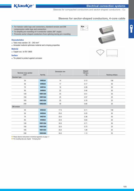
VHR354_GRP02
105
Electrical connection systems
Sleeves for compacted conductors and sector-shaped conductors - Cu
Sleeves for sector-shaped conductors, 4-core cable
For tubular cable lugs and connectors, standard version and DIN
compression cable lugs and connectors
To simplify pre-rounding of 4-conductor cables (90° angle)
Prevents sector shaped conductors from splicing during pre-rounding
Characteristics
▪ Total cross-section: 35 - 240 mm²
▪ Annealed material optimises material and crimping properties
Material
▪ Copper acc. to EN 13600
Surface
▪ Tin-plated to protect against corrosion
Nominal cross section mm² Part No.
Dimension mm Weight/100 pcs.
~ kg Packing unit/pcs l
Standard type
35 VHR354 14 0.13 100
50 VHR504 17 0.17 50
70 VHR704 18 0.28 50
95 VHR954 22 0.40 50
120 VHR1204 23 0.51 50
150 VHR1504 25 0.57 25
185 VHR1854 25 0.78 25
240 VHR2404 30 0.85 25
DIN version
35 VHD354 17.5 0.11 100
50 VHD504 25.0 0.25 50
70 VHD704 25.0 0.38 50
95 VHD954 32.0 0.63 50
120 VHD1204 32.0 0.71 50
150 VHD1504 32.0 0.73 25
185 VHD1854 35.0 1.09 25
240 VHD2404 35.0 1.13 25
Please observe instructions in technical appendix on page i-7
Pre-rounding dies see chapter "Crimping dies"
Klauke Hauptkatalog EN_DIN A5.indb 105 07.10.2014 12:16:51
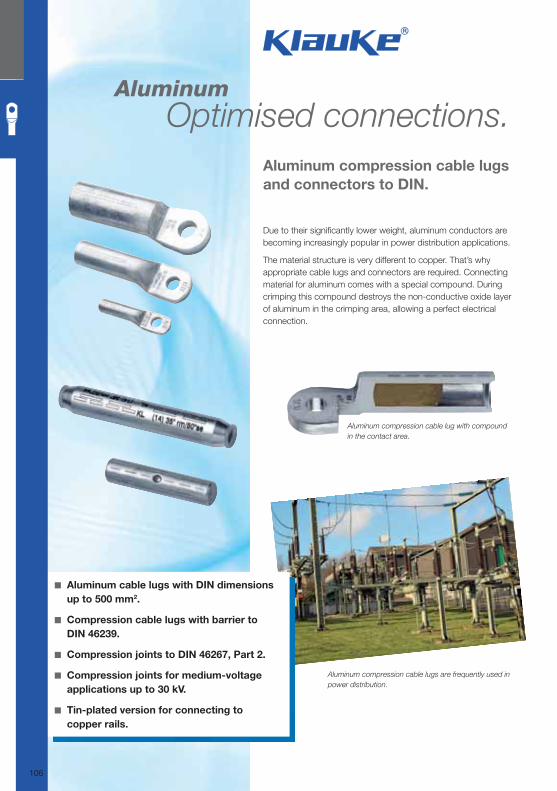
Aluminum Optimised connections.
Due to their signifi cantly lower weight, aluminum conductors are becoming increasingly popular in power distribution applications.
The material structure is very different to copper. That’s why appropriate cable lugs and connectors are required. Connecting material for aluminum comes with a special compound. During crimping this compound destroys the non-conductive oxide layer of aluminum in the crimping area, allowing a perfect electrical connection.
Aluminum compression cable lugs
and connectors to DIN.
◾ Aluminum cable lugs with DIN dimensions
up to 500 mm2.
◾ Compression cable lugs with barrier to
DIN 46239.
◾ Compression joints to DIN 46267, Part 2.
◾ Compression joints for medium-voltage
applications up to 30 kV.
◾ Tin-plated version for connecting to
copper rails.
Aluminum compression cable lugs are frequently used in
power distribution.
Aluminum compression cable lug with compound
in the contact area.
106
Klauke Hauptkatalog EN_DIN A5.indb 106 07.10.2014 12:16:51
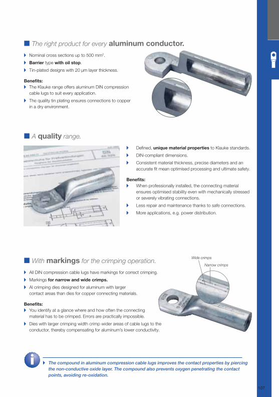
■ A quality range.
▸ Defi ned, unique material properties to Klauke standards.
▸ DIN-compliant dimensions.
▸ Consistent material thickness, precise diameters and an
accurate fi t mean optimised processing and ultimate safety.
Benefi ts: ▸ When professionally installed, the connecting material
ensures optimised stability even with mechanically stressed
or severely vibrating connections.
▸ Less repair and maintenance thanks to safe connections.
▸ More applications, e.g. power distribution.
■ With markings for the crimping operation.
▸ All DIN compression cable lugs have markings for correct crimping.
▸ Markings for narrow and wide crimps.
▸ Al crimping dies designed for aluminum with larger
contact areas than dies for copper connecting materials.
Benefi ts: ▸ You identify at a glance where and how often the connecting
material has to be crimped. Errors are practically impossible.
▸ Dies with larger crimping width crimp wider areas of cable lugs to the
conductor, thereby compensating for aluminum’s lower conductivity.
■ The right product for every aluminum conductor.
▸ Nominal cross sections up to 500 mm2.
▸ Barrier type with oil stop.
▸ Tin-plated designs with 20 μm layer thickness.
Benefi ts: ▸ The Klauke range offers aluminum DIN compression
cable lugs to suit every application.
▸ The quality tin plating ensures connections to copper
in a dry environment.
▸ The compound in aluminum compression cable lugs improves the contact properties by piercing the non-conductive oxide layer. The compound also prevents oxygen penetrating the contact points, avoiding re-oxidation.
Narrow crimps
Wide crimps
107
Klauke Hauptkatalog EN_DIN A5.indb 107 07.10.2014 12:16:53
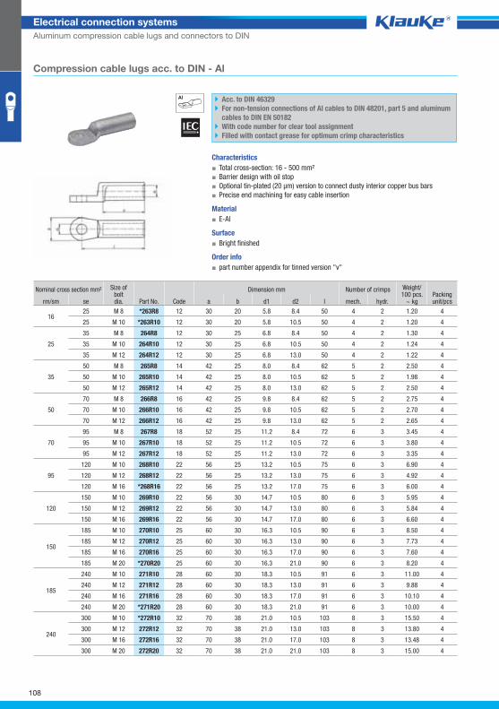
263r8grp
108
Electrical connection systems
Aluminum compression cable lugs and connectors to DIN
Compression cable lugs acc. to DIN - Al
Acc. to DIN 46329
For non-tension connections of Al cables to DIN 48201, part 5 and aluminum
cables to DIN EN 50182
With code number for clear tool assignment
Filled with contact grease for optimum crimp characteristics
Characteristics
▪ Total cross-section: 16 - 500 mm²
▪ Barrier design with oil stop
▪ Optional tin-plated (20 μm) version to connect dusty interior copper bus bars
▪ Precise end machining for easy cable insertion
Material
▪ E-Al
Surface
▪ Bright finished
Order info
▪ part number appendix for tinned version "v"
Nominal cross section mm² Size ofboltdia. Part No. Code
Dimension mm Number of crimps Weight/100 pcs.
~ kg Packing unit/pcs rm/sm se a b d1 d2 l mech. hydr.
16 25 M 8 *263R8 12 30 20 5.8 8.4 50 4 2 1.20 4
25 M 10 *263R10 12 30 20 5.8 10.5 50 4 2 1.20 4
25
35 M 8 264R8 12 30 25 6.8 8.4 50 4 2 1.30 4
35 M 10 264R10 12 30 25 6.8 10.5 50 4 2 1.24 4
35 M 12 264R12 12 30 25 6.8 13.0 50 4 2 1.22 4
35
50 M 8 265R8 14 42 25 8.0 8.4 62 5 2 2.50 4
50 M 10 265R10 14 42 25 8.0 10.5 62 5 2 1.98 4
50 M 12 265R12 14 42 25 8.0 13.0 62 5 2 2.50 4
50
70 M 8 266R8 16 42 25 9.8 8.4 62 5 2 2.75 4
70 M 10 266R10 16 42 25 9.8 10.5 62 5 2 2.70 4
70 M 12 266R12 16 42 25 9.8 13.0 62 5 2 2.65 4
70
95 M 8 267R8 18 52 25 11.2 8.4 72 6 3 3.45 4
95 M 10 267R10 18 52 25 11.2 10.5 72 6 3 3.80 4
95 M 12 267R12 18 52 25 11.2 13.0 72 6 3 3.35 4
95
120 M 10 268R10 22 56 25 13.2 10.5 75 6 3 6.90 4
120 M 12 268R12 22 56 25 13.2 13.0 75 6 3 4.92 4
120 M 16 *268R16 22 56 25 13.2 17.0 75 6 3 6.00 4
120
150 M 10 269R10 22 56 30 14.7 10.5 80 6 3 5.95 4
150 M 12 269R12 22 56 30 14.7 13.0 80 6 3 5.84 4
150 M 16 269R16 22 56 30 14.7 17.0 80 6 3 6.60 4
150
185 M 10 270R10 25 60 30 16.3 10.5 90 6 3 8.50 4
185 M 12 270R12 25 60 30 16.3 13.0 90 6 3 7.73 4
185 M 16 270R16 25 60 30 16.3 17.0 90 6 3 7.60 4
185 M 20 *270R20 25 60 30 16.3 21.0 90 6 3 8.20 4
185
240 M 10 271R10 28 60 30 18.3 10.5 91 6 3 11.00 4
240 M 12 271R12 28 60 30 18.3 13.0 91 6 3 9.88 4
240 M 16 271R16 28 60 30 18.3 17.0 91 6 3 10.10 4
240 M 20 *271R20 28 60 30 18.3 21.0 91 6 3 10.00 4
240
300 M 10 *272R10 32 70 38 21.0 10.5 103 8 3 15.50 4
300 M 12 272R12 32 70 38 21.0 13.0 103 8 3 13.80 4
300 M 16 272R16 32 70 38 21.0 17.0 103 8 3 13.48 4
300 M 20 272R20 32 70 38 21.0 21.0 103 8 3 15.00 4
Klauke Hauptkatalog EN_DIN A5.indb 108 07.10.2014 12:16:54
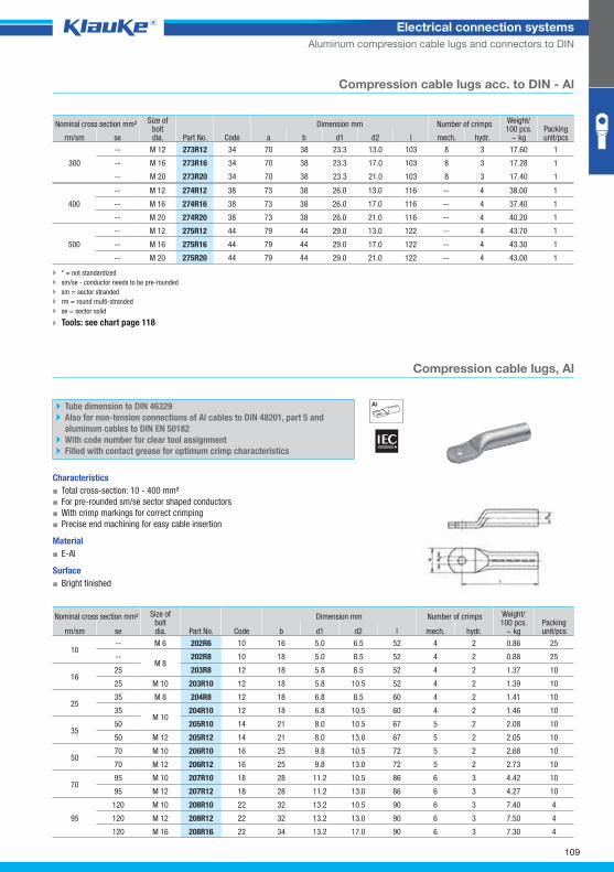
202r6grp
109
Electrical connection systems
Aluminum compression cable lugs and connectors to DIN
Compression cable lugs acc. to DIN - Al
Nominal cross section mm² Size ofboltdia. Part No. Code
Dimension mm Number of crimps Weight/100 pcs.
~ kg Packing unit/pcs rm/sm se a b d1 d2 l mech. hydr.
300
-- M 12 273R12 34 70 38 23.3 13.0 103 8 3 17.60 1
-- M 16 273R16 34 70 38 23.3 17.0 103 8 3 17.28 1
-- M 20 273R20 34 70 38 23.3 21.0 103 8 3 17.40 1
400
-- M 12 274R12 38 73 38 26.0 13.0 116 -- 4 38.00 1
-- M 16 274R16 38 73 38 26.0 17.0 116 -- 4 37.40 1
-- M 20 274R20 38 73 38 26.0 21.0 116 -- 4 40.20 1
500
-- M 12 275R12 44 79 44 29.0 13.0 122 -- 4 43.70 1
-- M 16 275R16 44 79 44 29.0 17.0 122 -- 4 43.30 1
-- M 20 275R20 44 79 44 29.0 21.0 122 -- 4 43.00 1
* = not standardized
sm/se - conductor needs to be pre-rounded
sm = sector stranded
rm = round multi-stranded
se = sector solid
Tools: see chart page 118
Compression cable lugs, Al
Tube dimension to DIN 46329
Also for non-tension connections of Al cables to DIN 48201, part 5 and
aluminum cables to DIN EN 50182
With code number for clear tool assignment
Filled with contact grease for optimum crimp characteristics
Characteristics
▪ Total cross-section: 10 - 400 mm²
▪ For pre-rounded sm/se sector shaped conductors
▪ With crimp markings for correct crimping
▪ Precise end machining for easy cable insertion
Material
▪ E-Al
Surface
▪ Bright finished
Nominal cross section mm² Size ofboltdia.
Dimension mm Number of crimps Weight/100 pcs.
~ kg Packing unit/pcs rm/sm se Part No. Code b d1 d2 l mech. hydr.
10 -- M 6 202R6 10 16 5.0 6.5 52 4 2 0.86 25
-- M 8
202R8 10 18 5.0 8.5 52 4 2 0.88 25
16 25 203R8 12 18 5.8 8.5 52 4 2 1.37 10
25 M 10 203R10 12 18 5.8 10.5 52 4 2 1.39 10
25 35 M 8 204R8 12 18 6.8 8.5 60 4 2 1.41 10
35 M 10
204R10 12 18 6.8 10.5 60 4 2 1.46 10
35 50 205R10 14 21 8.0 10.5 67 5 2 2.08 10
50 M 12 205R12 14 21 8.0 13.0 67 5 2 2.05 10
50 70 M 10 206R10 16 25 9.8 10.5 72 5 2 2.68 10
70 M 12 206R12 16 25 9.8 13.0 72 5 2 2.73 10
70 95 M 10 207R10 18 28 11.2 10.5 86 6 3 4.42 10
95 M 12 207R12 18 28 11.2 13.0 86 6 3 4.27 10
95
120 M 10 208R10 22 32 13.2 10.5 90 6 3 7.40 4
120 M 12 208R12 22 32 13.2 13.0 90 6 3 7.50 4
120 M 16 208R16 22 34 13.2 17.0 90 6 3 7.30 4
Klauke Hauptkatalog EN_DIN A5.indb 109 07.10.2014 12:16:54
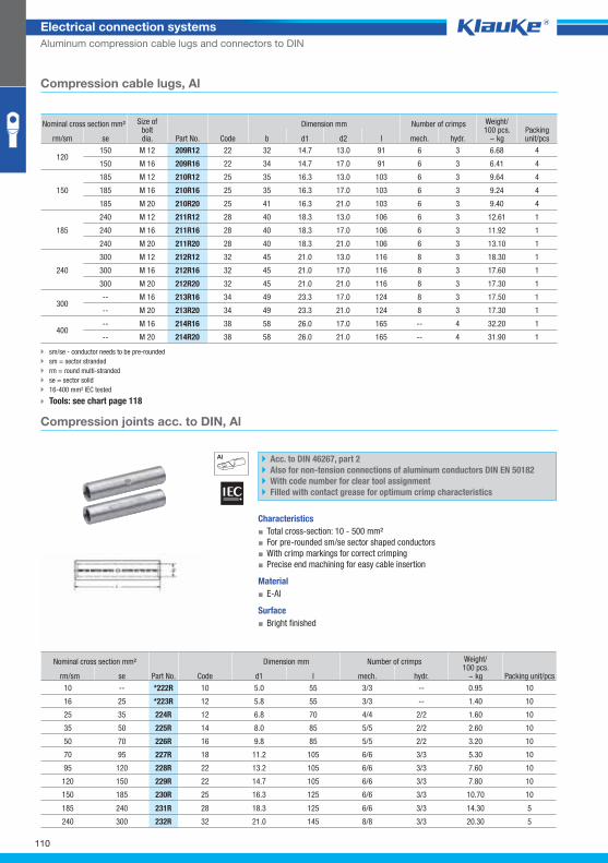
222rgrp
110
Electrical connection systems
Aluminum compression cable lugs and connectors to DIN
Compression cable lugs, Al
Nominal cross section mm² Size ofboltdia.
Dimension mm Number of crimps Weight/100 pcs.
~ kg Packing unit/pcs rm/sm se Part No. Code b d1 d2 l mech. hydr.
120 150 M 12 209R12 22 32 14.7 13.0 91 6 3 6.68 4
150 M 16 209R16 22 34 14.7 17.0 91 6 3 6.41 4
150
185 M 12 210R12 25 35 16.3 13.0 103 6 3 9.64 4
185 M 16 210R16 25 35 16.3 17.0 103 6 3 9.24 4
185 M 20 210R20 25 41 16.3 21.0 103 6 3 9.40 4
185
240 M 12 211R12 28 40 18.3 13.0 106 6 3 12.61 1
240 M 16 211R16 28 40 18.3 17.0 106 6 3 11.92 1
240 M 20 211R20 28 40 18.3 21.0 106 6 3 13.10 1
240
300 M 12 212R12 32 45 21.0 13.0 116 8 3 18.30 1
300 M 16 212R16 32 45 21.0 17.0 116 8 3 17.60 1
300 M 20 212R20 32 45 21.0 21.0 116 8 3 17.30 1
300 -- M 16 213R16 34 49 23.3 17.0 124 8 3 17.50 1
-- M 20 213R20 34 49 23.3 21.0 124 8 3 17.30 1
400 -- M 16 214R16 38 58 26.0 17.0 165 -- 4 32.20 1
-- M 20 214R20 38 58 26.0 21.0 165 -- 4 31.90 1
sm/se - conductor needs to be pre-rounded
sm = sector stranded
rm = round multi-stranded
se = sector solid
16-400 mm² IEC tested
Tools: see chart page 118
Compression joints acc. to DIN, Al
Acc. to DIN 46267, part 2
Also for non-tension connections of aluminum conductors DIN EN 50182
With code number for clear tool assignment
Filled with contact grease for optimum crimp characteristics
Characteristics
▪ Total cross-section: 10 - 500 mm²
▪ For pre-rounded sm/se sector shaped conductors
▪ With crimp markings for correct crimping
▪ Precise end machining for easy cable insertion
Material
▪ E-Al
Surface
▪ Bright finished
Nominal cross section mm²
Part No. Code
Dimension mm Number of crimps Weight/100 pcs.
~ kg Packing unit/pcs rm/sm se d1 l mech. hydr.
10 -- *222R 10 5.0 55 3/3 -- 0.95 10
16 25 *223R 12 5.8 55 3/3 -- 1.40 10
25 35 224R 12 6.8 70 4/4 2/2 1.60 10
35 50 225R 14 8.0 85 5/5 2/2 2.60 10
50 70 226R 16 9.8 85 5/5 2/2 3.20 10
70 95 227R 18 11.2 105 6/6 3/3 5.30 10
95 120 228R 22 13.2 105 6/6 3/3 7.60 10
120 150 229R 22 14.7 105 6/6 3/3 7.80 10
150 185 230R 25 16.3 125 6/6 3/3 10.70 10
185 240 231R 28 18.3 125 6/6 3/3 14.30 5
240 300 232R 32 21.0 145 8/8 3/3 20.30 5
Klauke Hauptkatalog EN_DIN A5.indb 110 07.10.2014 12:16:55
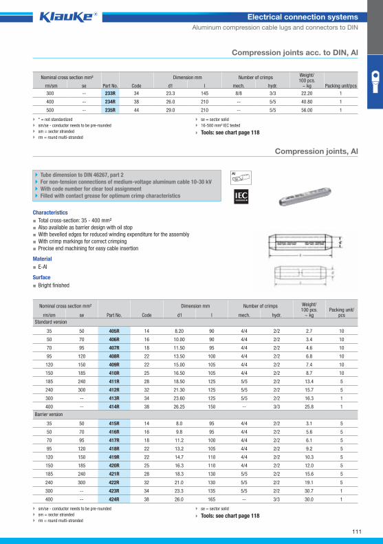
405r_GRP02
111
Electrical connection systems
Aluminum compression cable lugs and connectors to DIN
Compression joints acc. to DIN, Al
Nominal cross section mm²
Part No. Code
Dimension mm Number of crimps Weight/100 pcs.
~ kg Packing unit/pcs rm/sm se d1 l mech. hydr.
300 -- 233R 34 23.3 145 8/8 3/3 22.20 1
400 -- 234R 38 26.0 210 -- 5/5 40.80 1
500 -- 235R 44 29.0 210 -- 5/5 56.00 1
* = not standardized
sm/se - conductor needs to be pre-rounded
sm = sector stranded
rm = round multi-stranded
se = sector solid
16-500 mm² IEC tested
Tools: see chart page 118
Compression joints, Al
Tube dimension to DIN 46267, part 2
For non-tension connections of medium-voltage aluminum cable 10-30 kV
With code number for clear tool assignment
Filled with contact grease for optimum crimp characteristics
Characteristics
▪ Total cross-section: 35 - 400 mm²
▪ Also available as barrier design with oil stop
▪ With bevelled edges for reduced winding expenditure for the assembly
▪ With crimp markings for correct crimping
▪ Precise end machining for easy cable insertion
Material
▪ E-Al
Surface
▪ Bright finished
Nominal cross section mm² Dimension mm Number of crimps Weight/100 pcs.
~ kg Packing unit/
pcs rm/sm se Part No. Code d1 l mech. hydr.
Standard version
35 50 405R 14 8.20 90 4/4 2/2 2.7 10
50 70 406R 16 10.00 90 4/4 2/2 3.4 10
70 95 407R 18 11.50 95 4/4 2/2 4.6 10
95 120 408R 22 13.50 100 4/4 2/2 6.8 10
120 150 409R 22 15.00 105 4/4 2/2 7.4 10
150 185 410R 25 16.50 105 4/4 2/2 8.7 10
185 240 411R 28 18.50 125 5/5 2/2 13.4 5
240 300 412R 32 21.30 125 5/5 2/2 15.7 5
300 -- 413R 34 23.60 125 5/5 2/2 16.3 1
400 -- 414R 38 26.25 150 -- 3/3 25.8 1
Barrier version
35 50 415R 14 8.0 95 4/4 2/2 3.1 5
50 70 416R 16 9.8 95 4/4 2/2 5.6 5
70 95 417R 18 11.2 100 4/4 2/2 6.1 5
95 120 418R 22 13.2 105 4/4 2/2 9.2 5
120 150 419R 22 14.7 110 4/4 2/2 10.3 5
150 185 420R 25 16.3 110 4/4 2/2 12.0 5
185 240 421R 28 18.3 130 5/5 2/2 15.6 5
240 300 422R 32 21.0 130 5/5 2/2 19.1 5
300 -- 423R 34 23.3 135 5/5 2/2 30.7 1
400 -- 424R 38 26.0 165 -- 3/3 30.0 1
sm/se - conductor needs to be pre-rounded
sm = sector stranded
rm = round multi-stranded
se = sector solid
Tools: see chart page 118
Klauke Hauptkatalog EN_DIN A5.indb 111 07.10.2014 12:16:55
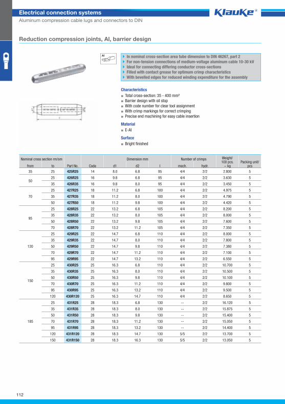
425r25grp
112
Electrical connection systems
Aluminum compression cable lugs and connectors to DIN
Reduction compression joints, Al, barrier design
In nominal cross-section area tube dimension to DIN 46267, part 2
For non-tension connections of medium-voltage aluminum cable 10-30 kV
Ideal for connecting differing conductor cross-sections
Filled with contact grease for optimum crimp characteristics
With bevelled edges for reduced winding expenditure for the assembly
Characteristics
▪ Total cross-section: 35 - 400 mm²
▪ Barrier design with oil stop
▪ With code number for clear tool assignment
▪ With crimp markings for correct crimping
▪ Precise end machining for easy cable insertion
Material
▪ E-Al
Surface
▪ Bright finished
Nominal cross section rm/sm
Part No. Code
Dimension mm Number of crimps Weight/100 pcs.
~ kg Packing unit/
pcs from to d1 d2 l mech. hydr.
35 25 425R25 14 8.0 6.8 95 4/4 2/2 2.800 5
50 25 426R25 16 9.8 6.8 95 4/4 2/2 3.630 5
35 426R35 16 9.8 8.0 95 4/4 2/2 3.450 5
70
25 427R25 18 11.2 6.8 100 4/4 2/2 4.975 5
35 427R35 18 11.2 8.0 100 4/4 2/2 4.790 5
50 427R50 18 11.2 9.8 100 4/4 2/2 4.420 5
95
25 428R25 22 13.2 6.8 105 4/4 2/2 8.200 5
35 428R35 22 13.2 8.0 105 4/4 2/2 8.000 5
50 428R50 22 13.2 9.8 105 4/4 2/2 7.600 5
70 428R70 22 13.2 11.2 105 4/4 2/2 7.350 5
120
25 429R25 22 14.7 6.8 110 4/4 2/2 8.000 5
35 429R35 22 14.7 8.0 110 4/4 2/2 7.800 5
50 429R50 22 14.7 9.8 110 4/4 2/2 7.380 5
70 429R70 22 14.7 11.2 110 4/4 2/2 7.100 5
95 429R95 22 14.7 13.2 110 4/4 2/2 6.550 5
150
25 430R25 25 16.3 6.8 110 4/4 2/2 10.700 5
35 430R35 25 16.3 8.0 110 4/4 2/2 10.500 5
50 430R50 25 16.3 9.8 110 4/4 2/2 10.100 5
70 430R70 25 16.3 11.2 110 4/4 2/2 9.800 5
95 430R95 25 16.3 13.2 110 4/4 2/2 9.500 5
120 430R120 25 16.3 14.7 110 4/4 2/2 8.650 5
185
25 431R25 28 18.3 6.8 130 -- 2/2 16.120 5
35 431R35 28 18.3 8.0 130 -- 2/2 15.875 5
50 431R50 28 18.3 9.8 130 -- 2/2 15.400 5
70 431R70 28 18.3 11.2 130 -- 2/2 15.050 5
95 431R95 28 18.3 13.2 130 -- 2/2 14.400 5
120 431R120 28 18.3 14.7 130 5/5 2/2 13.700 5
150 431R150 28 18.3 16.3 130 5/5 2/2 13.050 5
Klauke Hauptkatalog EN_DIN A5.indb 112 07.10.2014 12:16:56
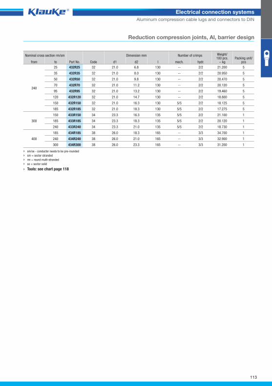
113
Electrical connection systems
Aluminum compression cable lugs and connectors to DIN
Reduction compression joints, Al, barrier design
Nominal cross section rm/sm
Part No. Code
Dimension mm Number of crimps Weight/100 pcs.
~ kg Packing unit/
pcs from to d1 d2 l mech. hydr.
240
25 432R25 32 21.0 6.8 130 -- 2/2 21.200 5
35 432R35 32 21.0 8.0 130 -- 2/2 20.950 5
50 432R50 32 21.0 9.8 130 -- 2/2 20.470 5
70 432R70 32 21.0 11.2 130 -- 2/2 20.120 5
95 432R95 32 21.0 13.2 130 -- 2/2 19.460 5
120 432R120 32 21.0 14.7 130 -- 2/2 18.800 5
150 432R150 32 21.0 16.3 130 5/5 2/2 18.125 5
185 432R185 32 21.0 18.3 130 5/5 2/2 17.275 5
300
150 433R150 34 23.3 16.3 135 5/5 2/2 21.100 1
185 433R185 34 23.3 18.3 135 5/5 2/2 20.120 1
240 433R240 34 23.3 21.0 135 5/5 2/2 18.730 1
400
185 434R185 38 26.0 18.3 165 -- 3/3 34.700 1
240 434R240 38 26.0 21.0 165 -- 3/3 32.900 1
300 434R300 38 26.0 23.3 165 -- 3/3 31.200 1
sm/se - conductor needs to be pre-rounded
sm = sector stranded
rm = round multi-stranded
se = sector solid
Tools: see chart page 118
Klauke Hauptkatalog EN_DIN A5.indb 113 07.10.2014 12:16:56
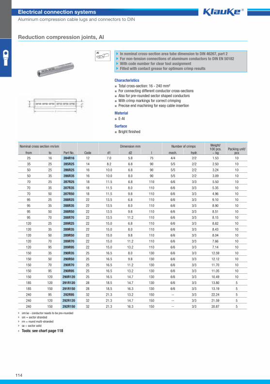
114
Electrical connection systems
Aluminum compression cable lugs and connectors to DIN
Reduction compression joints, Al
sm/se - conductor needs to be pre-rounded
sm = sector stranded
rm = round multi-stranded
se = sector solid
Tools: see chart page 118
In nominal cross-section area tube dimension to DIN 46267, part 2
For non-tension connections of aluminum conductors to DIN EN 50182
With code number for clear tool assignment
Filled with contact grease for optimum crimp results
Characteristics
▪ Total cross-section: 16 - 240 mm²
▪ For connecting different conductor cross-sections
▪ Also for pre-rounded sector shaped conductors
▪ With crimp markings for correct crimping
▪ Precise end machining for easy cable insertion
Material
▪ E-Al
Surface
▪ Bright finished
Nominal cross section rm/sm
Part No.
Dimension mm Number of crimps Weight/100 pcs.
~ kg Packing unit/
pcs from to Code d1 d2 l mech. hydr.
25 16 284R16 12 7.0 5.8 75 4/4 2/2 1.53 10
35 25 285R25 14 8.2 6.8 90 5/5 2/2 2.50 10
50 25 286R25 16 10.0 6.8 90 5/5 2/2 3.24 10
50 35 286R35 16 10.0 8.0 90 5/5 2/2 3.09 10
70 25 287R25 18 11.5 6.8 110 6/6 3/3 5.50 10
70 35 287R35 18 11.5 8.0 110 6/6 3/3 5.35 10
70 50 287R50 18 11.5 9.8 110 6/6 3/3 4.96 10
95 25 288R25 22 13.5 6.8 110 6/6 3/3 9.10 10
95 35 288R35 22 13.5 8.0 110 6/6 3/3 8.90 10
95 50 288R50 22 13.5 9.8 110 6/6 3/3 8.51 10
95 70 288R70 22 13.5 11.2 110 6/6 3/3 8.15 10
120 25 289R25 22 15.0 6.8 110 6/6 3/3 8.62 10
120 35 289R35 22 15.0 8.0 110 6/6 3/3 8.43 10
120 50 289R50 22 15.0 9.8 110 6/6 3/3 8.04 10
120 70 289R70 22 15.0 11.2 110 6/6 3/3 7.66 10
120 95 289R95 22 15.0 13.2 110 6/6 3/3 7.14 10
150 35 290R35 25 16.5 8.0 130 6/6 3/3 12.59 10
150 50 290R50 25 16.5 9.8 130 6/6 3/3 12.12 10
150 70 290R70 25 16.5 11.2 130 6/6 3/3 11.70 10
150 95 290R95 25 16.5 13.2 130 6/6 3/3 11.05 10
150 120 290R120 25 16.5 14.7 130 6/6 3/3 10.49 10
185 120 291R120 28 18.5 14.7 130 6/6 3/3 13.80 5
185 150 291R150 28 18.5 16.3 130 6/6 3/3 13.19 5
240 95 292R95 32 21.3 13.2 150 -- 3/3 22.24 5
240 120 292R120 32 21.3 14.7 150 -- 3/3 21.59 5
240 150 292R150 32 21.3 16.3 150 -- 3/3 20.87 5
Klauke Hauptkatalog EN_DIN A5.indb 114 07.10.2014 12:16:56
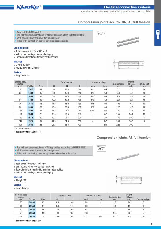
243rgrp
294adgrp
115
Electrical connection systems
Aluminum compression cable lugs and connectors to DIN
Compression joints acc. to DIN, Al, full tension
Acc. to DIN 48085, part 2
For full tension connections of aluminum conductors to DIN EN 50182
With code number for clear tool assignment
Filled with contact grease for optimum crimp results
Characteristics
▪ Total cross-section: 16 - 300 mm²
▪ With crimp markings for correct crimping
▪ Precise end machining for easy cable insertion
Material
▪ E-Al to 95 mm²
▪ AlMgSi 1w from 120 mm²
Surface
▪ Bright finished
Nominal cross
section mm² Part No. Code
Dimension mm Number of crimps Conductor dia.
mm
Weight/100 pcs.
~ kg Packing unit/
pcs d1 d4 l mech. hydr.
16 *243R 12 5.8 12.0 140 8/8 4/4 5.1 3.4 10
25 244R 12 6.8 12.0 140 8/8 4/4 6.3 2.9 10
35 245R 14 8.0 14.0 140 8/8 4/4 7.5 3.9 10
50 246R 16 10.0 16.0 155 8/8 4/4 9.0 5.2 10
70 247R 18 11.5 18.5 165 8/8 4/4 10.5 7.4 10
95 248R 22 13.5 22.0 165 8/8 4/4 12.5 12.2 10
120 249R 25 15.5 25.5 250 12/12 6/6 14.0 21.8 10
150 250R 28 16.5 28.5 300 -- 7/7 15.7 34.4 10
185 251R 28 18.5 28.5 330 -- 7/7 17.5 33.0 5
240 252R 34 21.5 34.5 350 -- 7/7 20.2 54.0 5
300 253R 38 23.5 38.5 400 -- 8/8 22.5 79.0 1
* = not standardized
Tools: see chart page 118
Compression joints, Al, full tension
AldreyFor full tension connections of Aldrey cables according to DIN EN 50182
With code number for clear tool assignment
Filled with contact grease for optimum crimp characteristics
Characteristics
▪ Total cross-section: 25 - 95 mm²
▪ With buttmarks for precise cable insertion
▪ Tube dimensions matched to aluminum steel cables
▪ With crimp markings for correct crimping
Material
▪ AlMgSi F20
Surface
▪ Bright finished
Tools: see chart page 120
Nominal cross section mm² Part No. Code
Dimension mm Number of crimps Conductor dia.
mm
Weight/100 pcs.
~ kg Packing unit/pcs d1 l mech. hydr.
25 294AD 12 6.8 140 8/8 -- 6.3 3.4 5
35 295AD 14 8.0 140 8/8 -- 7.5 4.7 5
50 296AD 16 10.0 155 8/8 -- 9.0 5.9 5
70 297AD 18 11.5 165 8/8 -- 10.5 9.0 5
95 298AD 20 13.5 165 10/10 5/5 12.5 10.2 5
Klauke Hauptkatalog EN_DIN A5.indb 115 07.10.2014 12:16:57
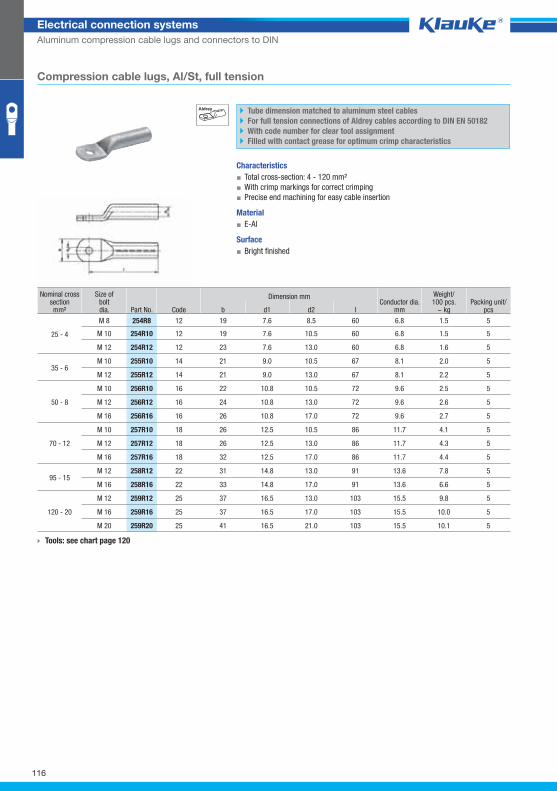
254r8grp
116
Electrical connection systems
Aluminum compression cable lugs and connectors to DIN
Compression cable lugs, Al/St, full tension
Aldrey Tube dimension matched to aluminum steel cables
For full tension connections of Aldrey cables according to DIN EN 50182
With code number for clear tool assignment
Filled with contact grease for optimum crimp characteristics
Characteristics
▪ Total cross-section: 4 - 120 mm²
▪ With crimp markings for correct crimping
▪ Precise end machining for easy cable insertion
Material
▪ E-Al
Surface
▪ Bright finished
Nominal cross section mm²
Size ofboltdia. Part No. Code
Dimension mm Conductor dia.
mm
Weight/100 pcs.
~ kg Packing unit/
pcs b d1 d2 l
25 - 4
M 8 254R8 12 19 7.6 8.5 60 6.8 1.5 5
M 10 254R10 12 19 7.6 10.5 60 6.8 1.5 5
M 12 254R12 12 23 7.6 13.0 60 6.8 1.6 5
35 - 6 M 10 255R10 14 21 9.0 10.5 67 8.1 2.0 5
M 12 255R12 14 21 9.0 13.0 67 8.1 2.2 5
50 - 8
M 10 256R10 16 22 10.8 10.5 72 9.6 2.5 5
M 12 256R12 16 24 10.8 13.0 72 9.6 2.6 5
M 16 256R16 16 26 10.8 17.0 72 9.6 2.7 5
70 - 12
M 10 257R10 18 26 12.5 10.5 86 11.7 4.1 5
M 12 257R12 18 26 12.5 13.0 86 11.7 4.3 5
M 16 257R16 18 32 12.5 17.0 86 11.7 4.4 5
95 - 15 M 12 258R12 22 31 14.8 13.0 91 13.6 7.8 5
M 16 258R16 22 33 14.8 17.0 91 13.6 6.6 5
120 - 20
M 12 259R12 25 37 16.5 13.0 103 15.5 9.8 5
M 16 259R16 25 37 16.5 17.0 103 15.5 10.0 5
M 20 259R20 25 41 16.5 21.0 103 15.5 10.1 5
Tools: see chart page 120
Klauke Hauptkatalog EN_DIN A5.indb 116 07.10.2014 12:16:57
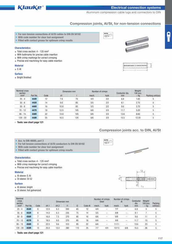
444rgrp
454rgrp
117
Electrical connection systems
Aluminum compression cable lugs and connectors to DIN
Compression joints, Al/St, for non-tension connections
For non-tension connections of Al/St cables to DIN EN 50182
With code number for clear tool assignment
Filled with contact grease for optimum crimp results
Characteristics
▪ Total cross-section: 4 - 120 mm²
▪ With buttmarks for precise cable insertion
▪ With crimp markings for correct crimping
▪ Precise end machining for easy cable insertion
Material
▪ E-Al
Surface
▪ Bright finished
Nominal cross section mm² Part No. Code
Dimension mm Number of crimps Conductor dia.
mm
Weight/100 pcs.
~ kg Packing unit/pcs d1 l mech. hydr.
25 - 4 444R 12 7.6 70 4/4 2/2 6.8 1.65 5
35 - 6 445R 14 9.0 85 5/5 2/2 8.1 2.75 5
50 - 8 446R 16 10.8 85 5/5 2/2 9.6 3.70 5
70 - 12 447R 18 12.5 105 6/6 3/3 11.7 5.20 5
95 - 15 448R 22 14.8 105 6/6 3/3 13.6 8.60 5
120 - 20 449R 25 16.5 125 6/6 3/3 15.5 12.20 5
Tools: see chart page 121
Compression joints acc. to DIN, Al/St
Acc. to DIN 48085, part 3
For full tension connections of Al/St conductors to DIN EN 50182
With code number for clear tool assignment
Filled with contact grease for optimum crimp results
Characteristics
▪ Total cross-section: 4 - 120 mm²
▪ With crimp markings for correct crimping
▪ Precise end machining for easy cable insertion
Material
▪ Al sleeve: E-Al
▪ St sleeve: St 52
Surface
▪ Al sleeve: bright
▪ St sleeve: hot galvanized
Nominal cross
section mm² Part No. Code
Dimension mm
Code Al
Number of crimpsSteel
Number of crimpsAl Conductor
dia.mm
Weight/100 pcs.
~ kg Packing unit/pcs d4.1 d4.2 l1 l2 mech. hydr. mech. hydr.
25 - 4 454R 6 12.0 6.3 200 65 12 4/4 -- 7/7 -- 6.8 5 5
35 - 6 455R 6 14.0 6.3 235 75 14 5/5 -- 8/8 -- 8.1 7 5
50 - 8 456R 7 16.0 7.5 270 95 16 6/6 -- 9/9 -- 9.6 11 5
70 - 12 457R 9 18.5 9.5 270 95 18 6/6 -- 9/9 -- 11.7 15 5
95 - 15 458R 9 22.5 9.6 310 95 22 6/6 -- 11/11 -- 13.6 23 5
120 - 20 459R 13 25.0 13.0 380 110 25 7/7 4/4 13/13 6/6 15.5 36 5
Tools: see chart page 121
Klauke Hauptkatalog EN_DIN A5.indb 117 07.10.2014 12:16:58
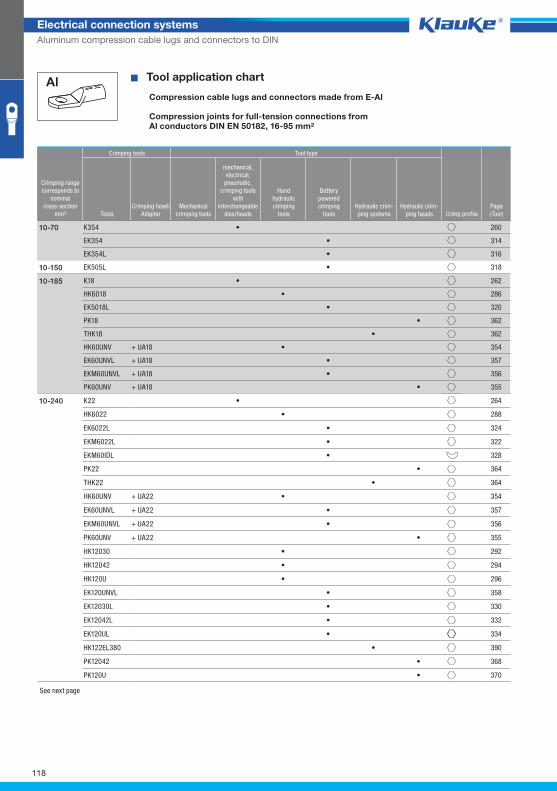
118
Electrical connection systems
Aluminum compression cable lugs and connectors to DIN
WZT_PKS_Al^ � Tool application chart
Compression cable lugs and connectors made from E-Al
Compression joints for full-tension connections fromAl conductors DIN EN 50182, 16-95 mm²
Crimping tools Tool type
Crimping rangecorresponds to
nominalcross-section
mm² ToolsCrimping head/
AdapterMechanical
crimping tools
mechanical,electrical,
pneumatic, crimping tools
with interchangeable
dies/heads
Handhydraulic crimping
tools
Batterypowered crimping
toolsHydraulic crim-ping systems
Hydraulic crim-ping heads Crimp profile
Page(Tool)
K354 • 260
EK354 • 314
EK354L • 316
10-70
EK505L • 31810-150
K18 • 262
HK6018 • 286
EK5018L • 320
PK18 • 362
THK18 • 362
HK60UNV + UA18 • 354
EK60UNVL + UA18 • 357
EKM60UNVL + UA18 • 356
PK60UNV + UA18 • 355
10-185
K22 • 264
HK6022 • 288
EK6022L • 324
EKM6022L • 322
EKM60IDL • 328
PK22 • 364
THK22 • 364
HK60UNV + UA22 • 354
EK60UNVL + UA22 • 357
EKM60UNVL + UA22 • 356
PK60UNV + UA22 • 355
HK12030 • 292
HK12042 • 294
HK120U • 296
EK120UNVL • 358
EK12030L • 330
EK12042L • 332
EK120UL • 334
HK122EL380 • 390
PK12042 • 368
PK120U • 370
10-240
See next page
Klauke Hauptkatalog EN_DIN A5.indb 118 07.10.2014 12:16:58
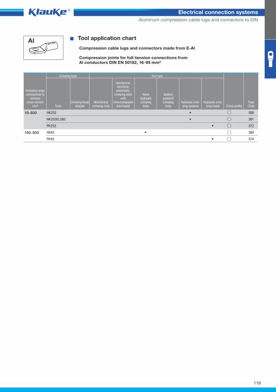
119
Electrical connection systems
Aluminum compression cable lugs and connectors to DIN
� Tool application chart
Compression cable lugs and connectors made from E-Al
Compression joints for full-tension connections fromAl conductors DIN EN 50182, 16-95 mm²
Crimping tools Tool type
Crimping rangecorresponds to
nominalcross-section
mm² ToolsCrimping head/
AdapterMechanical
crimping tools
mechanical,electrical,
pneumatic, crimping tools
with interchangeable
dies/heads
Handhydraulic crimping
tools
Batterypowered crimping
toolsHydraulic crim-ping systems
Hydraulic crim-ping heads Crimp profile
Page(Tool)
HK252 • 388
HK252EL380 • 391
PK252 • 372
10-500
HK45 • 389
PK45 • 374
150-500
Klauke Hauptkatalog EN_DIN A5.indb 119 07.10.2014 12:16:59
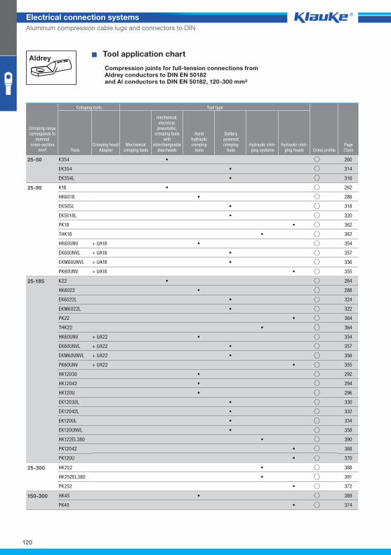
120
Electrical connection systems
Aluminum compression cable lugs and connectors to DIN
^WZT_PV_Aldrey^
Aldrey � Tool application chart
Compression joints for full-tension connections fromAldrey conductors to DIN EN 50182and Al conductors to DIN EN 50182, 120-300 mm²
Crimping tools Tool type
Crimping rangecorresponds to
nominalcross-section
mm² ToolsCrimping head/
AdapterMechanical
crimping tools
mechanical,electrical,
pneumatic, crimping tools
with interchangeable
dies/heads
Handhydraulic crimping
tools
Batterypowered crimping
toolsHydraulic crim-ping systems
Hydraulic crim-ping heads Crimp profile
Page(Tool)
K354 • 260
EK354 • 314
EK354L • 316
25-50
K18 • 262
HK6018 • 286
EK505L • 318
EK5018L • 320
PK18 • 362
THK18 • 362
HK60UNV + UA18 • 354
EK60UNVL + UA18 • 357
EKM60UNVL + UA18 • 356
PK60UNV + UA18 • 355
25-95
K22 • 264
HK6022 • 288
EK6022L • 324
EKM6022L • 322
PK22 • 364
THK22 • 364
HK60UNV + UA22 • 354
EK60UNVL + UA22 • 357
EKM60UNVL + UA22 • 356
PK60UNV + UA22 • 355
HK12030 • 292
HK12042 • 294
HK120U • 296
EK12030L • 330
EK12042L • 332
EK120UL • 334
EK120UNVL • 358
HK122EL380 • 390
PK12042 • 368
PK120U • 370
25-185
HK252 • 388
HK252EL380 • 391
PK252 • 372
25-300
HK45 • 389
PK45 • 374
150-300
Klauke Hauptkatalog EN_DIN A5.indb 120 07.10.2014 12:16:59
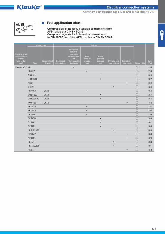
121
Electrical connection systems
Aluminum compression cable lugs and connectors to DIN
^WZT_PV_AlSt^ � Tool application chart
Compression joints for full-tension connections fromAl/St. cables to DIN EN 50182Compression joints for full-tension connectionsto DIN 48085, part 3 for Al/St. cables to DIN EN 50182
Crimping tools Tool type
Crimping rangecorresponds to
nominalcross-section
mm² ToolsCrimping head/
AdapterMechanical
crimping tools
mechanical,electrical,
pneumatic, crimping tools
with interchangeable
dies/heads
Handhydraulic crimping
tools
Batterypowered crimping
toolsHydraulic crim-ping systems
Hydraulic crim-ping heads Crimp profile
Page(Tool)
K22 • 264
HK6022 • 288
EK6022L • 324
EKM6022L • 322
PK22 • 364
THK22 • 364
HK60UNV + UA22 • 354
EK60UNVL + UA22 • 357
EKM60UNVL + UA22 • 356
PK60UNV + UA22 • 355
HK12030 • 292
HK12042 • 294
HK120U • 296
EK12030L • 330
EK12042L • 332
EK120UL • 334
HK122EL380 • 390
PK12042 • 368
PK120U • 370
HK252 • 388
HK252EL380 • 391
PK252 • 372
25/4-120/20
Klauke Hauptkatalog EN_DIN A5.indb 121 07.10.2014 12:16:59
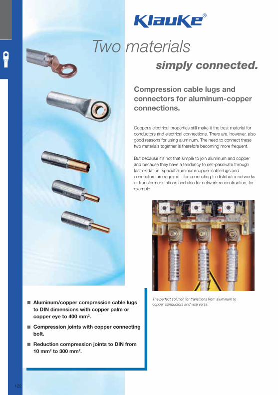
Two materials simply connected.
Copper’s electrical properties still make it the best material for conductors and electrical connections. There are, however, also good reasons for using aluminum. The need to connect these two materials together is therefore becoming more frequent.
But because it’s not that simple to join aluminum and copper and because they have a tendency to self-passivate through fast oxidation, special aluminum/copper cable lugs and connectors are required - for connecting to distributor networks or transformer stations and also for network reconstruction, for example.
Compression cable lugs and
connectors for aluminum-copper
connections.
◾ Aluminum/copper compression cable lugs
to DIN dimensions with copper palm or
copper eye to 400 mm2.
◾ Compression joints with copper connecting
bolt.
◾ Reduction compression joints to DIN from
10 mm2 to 300 mm2.
The perfect solution for transitions from aluminum to
copper conductors and vice versa.
122
Klauke Hauptkatalog EN_DIN A5.indb 122 07.10.2014 12:16:59
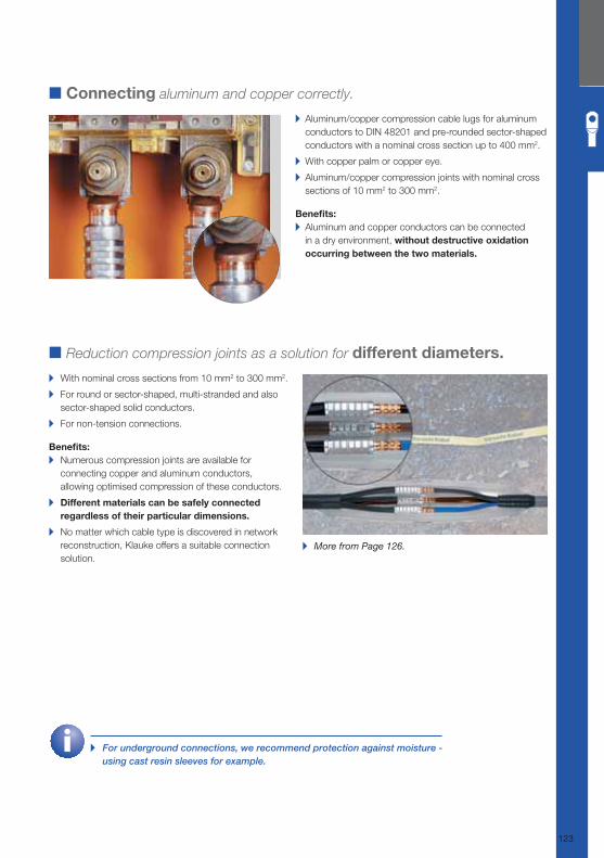
▸ For underground connections, we recommend protection against moisture - using cast resin sleeves for example.
■ Connecting aluminum and copper correctly.
▸ Aluminum/copper compression cable lugs for aluminum
conductors to DIN 48201 and pre-rounded sector-shaped
conductors with a nominal cross section up to 400 mm2.
▸ With copper palm or copper eye.
▸ Aluminum/copper compression joints with nominal cross
sections of 10 mm2 to 300 mm2.
Benefi ts: ▸ Aluminum and copper conductors can be connected
in a dry environment, without destructive oxidation
occurring between the two materials.
■ Reduction compression joints as a solution for different diameters.
▸ With nominal cross sections from 10 mm2 to 300 mm2.
▸ For round or sector-shaped, multi-stranded and also
sector-shaped solid conductors.
▸ For non-tension connections.
Benefi ts: ▸ Numerous compression joints are available for
connecting copper and aluminum conductors,
allowing optimised compression of these conductors.
▸ Different materials can be safely connected
regardless of their particular dimensions.
▸ No matter which cable type is discovered in network
reconstruction, Klauke offers a suitable connection
solution.
▸ More from Page 126.
123
Klauke Hauptkatalog EN_DIN A5.indb 123 07.10.2014 12:17:00
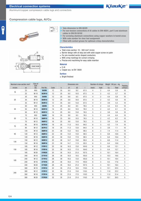
363r8grp
124
Electrical connection systems
Aluminum/copper compression cable lugs and connectors
Compression cable lugs, Al/Cu
Tube dimension to DIN 46329
For non-tension connections of Al cables to DIN 48201, part 5 and aluminum
cables to DIN EN 50182
For screwing aluminum connections using copper washers in humid areas
With code number for clear tool assignment
Filled with contact grease for optimum crimp characteristics
Characteristics
▪ Total cross-section: 16 - 300 mm² rm/sm
▪ Barrier design with oil stop and with solid copper screw-on palm
▪ For pre-rounded sector shaped conductors
▪ With crimp markings for correct crimping
▪ Precise end machining for easy cable insertion
Material
▪ E-Al
▪ Copper acc. to EN 13600
Surface
▪ Bright finished
Nominal cross section mm² Size ofboltdia. Part No.
Dimension mm Number of crimps Weight 100 pcs. ~kg Packing unit/pcs rm/sm se Code b d1 d2 l mech. hydr. Cu Total
16 25 M 8 363R8 12 25 6.0 8.5 67.5 4 2 4.4 5.9 10
25 M 10 363R10 12 25 6.0 10.5 67.5 4 2 4.2 5.7 10
25
35 M 8 364R8 12 25 6.8 8.5 67.5 4 2 4.4 5.8 10
35 M 10 364R10 12 25 6.8 10.5 67.5 4 2 4.2 5.6 10
35 M 12 364R12 12 25 6.8 13.0 67.5 4 2 3.9 5.3 10
35
50 M 8 365R8 14 25 8.0 8.5 76.5 5 2 4.4 6.3 10
50 M 10 365R10 14 25 8.0 10.5 76.5 5 2 4.2 6.1 10
50 M 12 365R12 14 25 8.0 13.0 76.5 5 2 3.8 5.8 10
50
70 M 8 366R8 16 25 9.8 8.5 76.5 5 2 4.4 6.4 10
70 M 10 366R10 16 25 9.8 10.5 76.5 5 2 4.2 6.2 10
70 M 12 366R12 16 25 9.8 13.0 76.5 5 2 3.9 5.9 10
70 95 M 10 367R10 18 25 11.2 10.5 84.5 6 3 4.2 7.4 10
95 M 12 367R12 18 25 11.2 13.0 84.5 6 3 3.9 7.1 10
95
120 M 10 368R10 22 30 13.2 10.5 90.5 6 3 7.4 11.4 10
120 M 12 368R12 22 30 13.2 13.0 90.5 6 3 6.8 10.8 10
120 M 16 368R16 22 30 13.2 17.0 90.5 6 3 6.4 10.4 10
120 150 M 12 369R12 22 30 14.7 13.0 92.0 6 3 6.8 11.4 5
150 M 16 369R16 22 30 14.7 17.0 92.0 6 3 6.4 10.8 5
150
185 M 12 370R12 25 30 16.3 13.0 104.0 6 3 6.8 13.1 5
185 M 16 370R16 25 30 16.3 17.0 104.0 6 3 6.4 12.7 5
185 M 20 370R20 25 35 16.3 21.0 107.5 6 3 10.1 16.4 5
185
240 M 10 371R10 28 30 18.3 10.5 105.0 6 3 10.3 18.6 5
240 M 12 371R12 28 30 18.3 13.0 105.0 6 3 10.1 18.4 5
240 M 16 371R16 28 30 18.3 17.0 105.0 6 3 9.3 17.6 5
240 M 20 371R20 28 35 18.3 21.0 107.5 6 3 10.1 18.4 5
240
300 M 10 372R10 32 35 21.0 10.5 118.5 8 3 12.1 22.5 5
300 M 12 372R12 32 35 21.0 13.0 118.5 8 3 11.8 22.2 5
300 M 16 372R16 32 35 21.0 17.0 118.5 8 3 11.0 21.4 5
300 M 20 372R20 32 35 21.0 21.0 118.5 8 3 10.1 20.5 5
Klauke Hauptkatalog EN_DIN A5.indb 124 07.10.2014 12:17:01
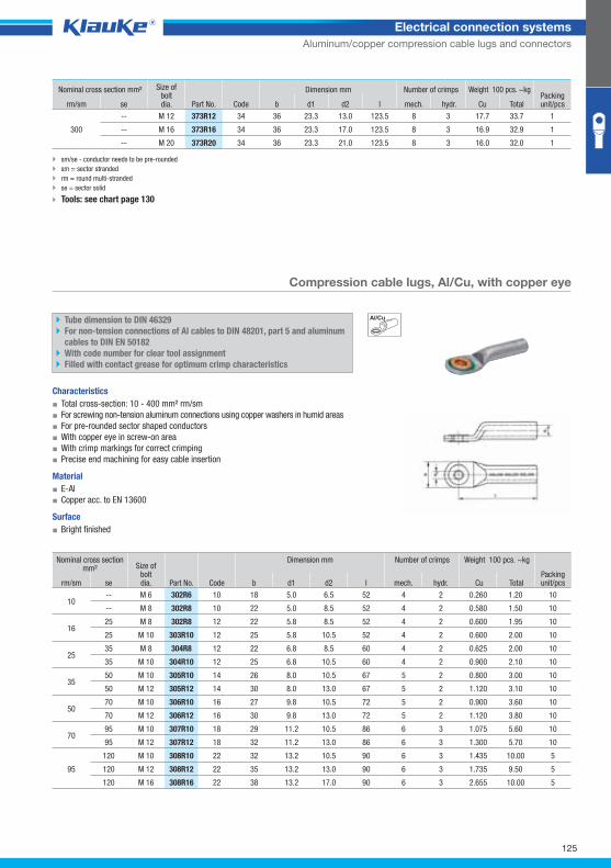
302r6grp
125
Electrical connection systems
Aluminum/copper compression cable lugs and connectors
sm/se - conductor needs to be pre-rounded
sm = sector stranded
rm = round multi-stranded
se = sector solid
Tools: see chart page 130
Compression cable lugs, Al/Cu, with copper eye
Tube dimension to DIN 46329
For non-tension connections of Al cables to DIN 48201, part 5 and aluminum
cables to DIN EN 50182
With code number for clear tool assignment
Filled with contact grease for optimum crimp characteristics
Characteristics
▪ Total cross-section: 10 - 400 mm² rm/sm
▪ For screwing non-tension aluminum connections using copper washers in humid areas
▪ For pre-rounded sector shaped conductors
▪ With copper eye in screw-on area
▪ With crimp markings for correct crimping
▪ Precise end machining for easy cable insertion
Material
▪ E-Al
▪ Copper acc. to EN 13600
Surface
▪ Bright finished
Nominal cross section mm² Size of
boltdia. Part No. Code
Dimension mm Number of crimps Weight 100 pcs. ~kg
Packing unit/pcs rm/sm se b d1 d2 l mech. hydr. Cu Total
10 -- M 6 302R6 10 18 5.0 6.5 52 4 2 0.260 1.20 10
-- M 8 302R8 10 22 5.0 8.5 52 4 2 0.580 1.50 10
16 25 M 8 302R8 12 22 5.8 8.5 52 4 2 0.600 1.95 10
25 M 10 303R10 12 25 5.8 10.5 52 4 2 0.600 2.00 10
25 35 M 8 304R8 12 22 6.8 8.5 60 4 2 0.625 2.00 10
35 M 10 304R10 12 25 6.8 10.5 60 4 2 0.900 2.10 10
35 50 M 10 305R10 14 26 8.0 10.5 67 5 2 0.800 3.00 10
50 M 12 305R12 14 30 8.0 13.0 67 5 2 1.120 3.10 10
50 70 M 10 306R10 16 27 9.8 10.5 72 5 2 0.900 3.60 10
70 M 12 306R12 16 30 9.8 13.0 72 5 2 1.120 3.80 10
70 95 M 10 307R10 18 29 11.2 10.5 86 6 3 1.075 5.60 10
95 M 12 307R12 18 32 11.2 13.0 86 6 3 1.300 5.70 10
95
120 M 10 308R10 22 32 13.2 10.5 90 6 3 1.435 10.00 5
120 M 12 308R12 22 35 13.2 13.0 90 6 3 1.735 9.50 5
120 M 16 308R16 22 38 13.2 17.0 90 6 3 2.655 10.00 5
Nominal cross section mm² Size ofboltdia. Part No.
Dimension mm Number of crimps Weight 100 pcs. ~kg Packing unit/pcs rm/sm se Code b d1 d2 l mech. hydr. Cu Total
300
-- M 12 373R12 34 36 23.3 13.0 123.5 8 3 17.7 33.7 1
-- M 16 373R16 34 36 23.3 17.0 123.5 8 3 16.9 32.9 1
-- M 20 373R20 34 36 23.3 21.0 123.5 8 3 16.0 32.0 1
Klauke Hauptkatalog EN_DIN A5.indb 125 07.10.2014 12:17:01
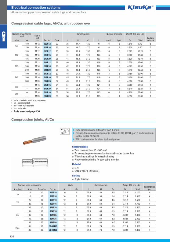
322r10grp
126
Electrical connection systems
Aluminum/copper compression cable lugs and connectors
Compression cable lugs, Al/Cu, with copper eye
Nominal cross section mm² Size of
boltdia. Part No. Code
Dimension mm Number of crimps Weight 100 pcs. ~kg
Packing unit/pcs rm/sm se b d1 d2 l mech. hydr. Cu Total
120 150 M 12 309R12 22 35 14.7 13.0 91 6 3 1.810 8.70 5
150 M 16 309R16 22 38 14.7 17.0 91 6 3 2.230 8.80 5
150
185 M 12 310R12 25 35 16.3 13.0 103 6 3 2.025 12.20 5
185 M 16 310R16 25 41 16.3 17.0 103 6 3 2.655 12.30 5
185 M 20 310R20 25 44 16.3 21.0 103 6 3 3.620 12.80 5
185
240 M 12 311R12 28 40 18.3 13.0 106 6 3 2.320 15.00 5
240 M 16 311R16 28 42 18.3 17.0 106 6 3 4.975 15.50 5
240 M 20 311R20 28 46 18.3 21.0 106 6 3 4.610 15.50 5
240
300 M 12 312R12 32 45 21.0 13.0 116 8 3 2.750 20.00 5
300 M 16 312R16 32 45 21.0 17.0 116 8 3 3.400 21.00 5
300 M 20 312R20 32 49 21.0 21.0 116 8 3 4.600 22.00 5
300 -- M 16 313R16 34 51 23.3 17.0 124 8 3 3.980 21.60 1
-- M 20 313R20 34 51 23.3 21.0 124 8 3 5.510 22.20 1
400 -- M 16 314R16 38 58 26.0 17.0 165 -- 4 4.200 35.00 1
-- M 20 314R20 38 58 26.0 21.0 165 -- 4 5.950 35.00 1
sm/se - conductor needs to be pre-rounded
sm = sector stranded
rm = round multi-stranded
se = sector solid
Tools: see chart page 130
Compression joints, Al/Cu
Tube dimensions to DIN 46267 part 1 and 2
For non-tension connections of Al cables to DIN 48201, part 5 and aluminum
cables to DIN EN 50182
With code number for clear tool assignment
Characteristics
▪ Total cross-section: 10 - 300 mm²
▪ For connecting non-tension aluminum and copper connections
▪ With crimp markings for correct crimping
▪ Precise end machining for easy cable insertion
Material
▪ E-Al
▪ Copper acc. to EN 13600
Surface
▪ Bright finished
Nominal cross section mm² Code Dimension mm Weight 100 pcs. ~kg
Packing unit/pcs Al rm/sm Al se Cu rm/sm Part No. Al Cu l Al Cu Cu Total
10 16 10 322R10 10 6 55.0 5.0 4.5 0.212 1.100 4
16 16 322R16 10 8 61.0 5.0 5.4 0.714 1.550 4
16 25 10 323R10 12 6 55.0 6.0 4.5 0.212 1.500 4
25 16 323R16 12 8 61.0 6.0 5.4 0.714 1.750 4
25
35 10 324R10 12 6 55.0 6.8 4.5 0.212 1.400 4
35 16 324R16 12 8 61.0 6.8 5.5 0.714 1.650 4
35 25 324R25 12 10 61.0 6.8 7.0 0.892 1.900 4
35 35 324R35 12 12 61.0 6.8 8.2 1.624 2.000 4
35 50 324R50 12 14 72.0 6.8 10.0 2.362 3.500 4
25/4 35 16 324R416 12 8 61.0 7.6 5.5 0.714 1.600 4
35 25 324R425 12 10 61.0 7.6 7.0 0.892 1.850 4
Klauke Hauptkatalog EN_DIN A5.indb 126 07.10.2014 12:17:02
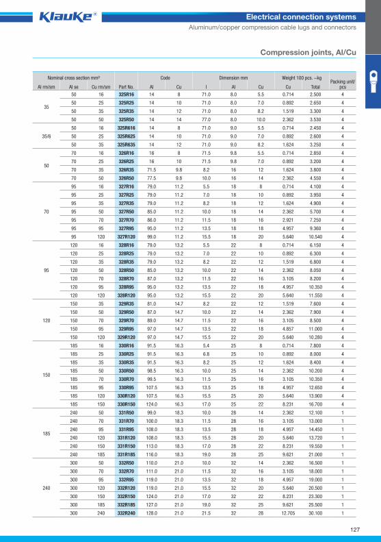
127
Electrical connection systems
Aluminum/copper compression cable lugs and connectors
Compression joints, Al/Cu
Nominal cross section mm² Code Dimension mm Weight 100 pcs. ~kg Packing unit/
pcs Al rm/sm Al se Cu rm/sm Part No. Al Cu l Al Cu Cu Total
35
50 16 325R16 14 8 71.0 8.0 5.5 0.714 2.500 4
50 25 325R25 14 10 71.0 8.0 7.0 0.892 2.650 4
50 35 325R35 14 12 71.0 8.0 8.2 1.519 3.300 4
50 50 325R50 14 14 77.0 8.0 10.0 2.362 3.530 4
35/6
50 16 325R616 14 8 71.0 9.0 5.5 0.714 2.450 4
50 25 325R625 14 10 71.0 9.0 7.0 0.892 2.600 4
50 35 325R635 14 12 71.0 9.0 8.2 1.624 3.250 4
50
70 16 326R16 16 8 71.5 9.8 5.5 0.714 2.850 4
70 25 326R25 16 10 71.5 9.8 7.0 0.892 3.200 4
70 35 326R35 71.5 9.8 8.2 16 12 1.624 3.800 4
70 50 326R50 77.5 9.8 10.0 16 14 2.362 4.550 4
70
95 16 327R16 79.0 11.2 5.5 18 8 0.714 4.100 4
95 25 327R25 79.0 11.2 7.0 18 10 0.892 3.950 4
95 35 327R35 79.0 11.2 8.2 18 12 1.624 4.900 4
95 50 327R50 85.0 11.2 10.0 18 14 2.362 5.700 4
95 70 327R70 86.0 11.2 11.5 18 16 2.921 7.250 4
95 95 327R95 95.0 11.2 13.5 18 18 4.957 9.360 4
95 120 327R120 99.0 11.2 15.5 18 20 5.640 10.540 4
95
120 16 328R16 79.0 13.2 5.5 22 8 0.714 6.150 4
120 25 328R25 79.0 13.2 7.0 22 10 0.892 6.300 4
120 35 328R35 79.0 13.2 8.2 22 12 1.519 6.800 4
120 50 328R50 85.0 13.2 10.0 22 14 2.362 8.050 4
120 70 328R70 87.0 13.2 11.5 22 16 3.105 8.200 4
120 95 328R95 95.0 13.2 13.5 22 18 4.957 10.350 4
120 120 328R120 95.0 13.2 15.5 22 20 5.640 11.550 4
120
150 35 329R35 81.0 14.7 8.2 22 12 1.519 7.600 4
150 50 329R50 87.0 14.7 10.0 22 14 2.362 7.900 4
150 70 329R70 89.0 14.7 11.5 22 16 3.105 8.500 4
150 95 329R95 97.0 14.7 13.5 22 18 4.857 11.000 4
150 120 329R120 97.0 14.7 15.5 22 20 5.640 10.280 4
150
185 16 330R16 91.5 16.3 5.4 25 8 0.714 7.800 4
185 25 330R25 91.5 16.3 6.8 25 10 0.892 8.000 4
185 35 330R35 91.5 16.3 8.2 25 12 1.624 8.400 4
185 50 330R50 98.5 16.3 10.0 25 14 2.362 10.200 4
185 70 330R70 99.5 16.3 11.5 25 16 3.105 10.350 4
185 95 330R95 107.5 16.3 13.5 25 18 4.957 12.650 4
185 120 330R120 107.5 16.3 15.5 25 20 5.640 13.900 4
185 150 330R150 124.0 16.3 17.0 25 22 8.231 16.700 4
185
240 50 331R50 99.0 18.3 10.0 28 14 2.362 12.100 1
240 70 331R70 100.0 18.3 11.5 28 16 3.105 13.000 1
240 95 331R95 108.0 18.3 13.5 28 18 4.957 14.450 1
240 120 331R120 108.0 18.3 15.5 28 20 5.640 13.720 1
240 150 331R150 113.0 18.3 17.0 28 22 8.231 19.550 1
240 185 331R185 116.0 18.3 19.0 28 25 9.621 21.000 1
240
300 50 332R50 110.0 21.0 10.0 32 14 2.362 16.500 1
300 70 332R70 111.0 21.0 11.5 32 16 3.105 18.000 1
300 95 332R95 119.0 21.0 13.5 32 18 4.957 19.000 1
300 120 332R120 119.0 21.0 15.5 32 20 5.640 20.500 1
300 150 332R150 124.0 21.0 17.0 32 22 8.231 23.300 1
300 185 332R185 127.0 21.0 19.0 32 25 9.621 25.500 1
300 240 332R240 128.0 21.0 21.5 32 28 12.705 30.100 1
Klauke Hauptkatalog EN_DIN A5.indb 127 07.10.2014 12:17:02
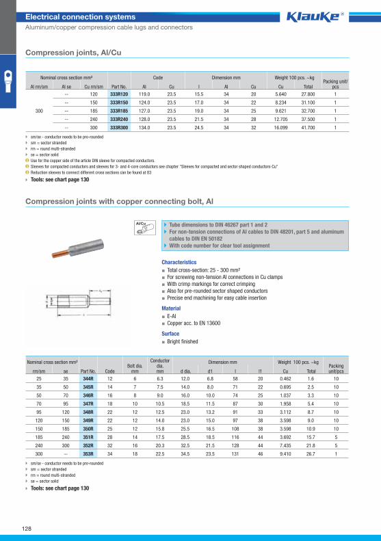
344rgrp
128
Electrical connection systems
Aluminum/copper compression cable lugs and connectors
sm/se - conductor needs to be pre-rounded
sm = sector stranded
rm = round multi-stranded
se = sector solid
Use for the copper side of the article DIN sleeve for compacted conductors.
Sleeves for compacted conductors and sleeves for 3- and 4-core conductors see chapter "Sleeves for compacted and sector shaped conductors-Cu"
Reduction sleeves to connect different cross sections can be found at 83
T ools: see chart page 130
Compression joints with copper connecting bolt, Al
Tube dimensions to DIN 46267 part 1 and 2
For non-tension connections of Al cables to DIN 48201, part 5 and aluminum
cables to DIN EN 50182
With code number for clear tool assignment
Characteristics
▪ Total cross-section: 25 - 300 mm²
▪ For screwing non-tension Al connections in Cu clamps
▪ With crimp markings for correct crimping
▪ Also for pre-rounded sector shaped conductors
▪ Precise end machining for easy cable insertion
Material
▪ E-Al
▪ Copper acc. to EN 13600
Surface
▪ Bright finished
Nominal cross section mm² Bolt dia.
mm
Conductor dia.mm
Dimension mm Weight 100 pcs. ~kg Packing unit/pcs rm/sm se Part No. Code d dia. d1 l l1 Cu Total
25 35 344R 12 6 6.3 12.0 6.8 58 20 0.462 1.6 10
35 50 345R 14 7 7.5 14.0 8.0 71 22 0.695 2.5 10
50 70 346R 16 8 9.0 16.0 10.0 74 25 1.037 3.3 10
70 95 347R 18 10 10.5 18.5 11.5 87 30 1.958 5.4 10
95 120 348R 22 12 12.5 23.0 13.2 91 33 3.112 8.7 10
120 150 349R 22 12 14.0 23.0 15.0 97 38 3.598 9.0 10
150 185 350R 25 12 15.8 25.5 16.5 108 38 3.598 10.9 10
185 240 351R 28 14 17.5 28.5 18.5 116 44 3.692 15.7 5
240 300 352R 32 16 20.3 32.5 21.5 128 44 7.435 21.8 5
300 -- 353R 34 18 22.5 34.5 23.5 131 46 9.410 26.7 1
sm/se - conductor needs to be pre-rounded
sm = sector stranded
rm = round multi-stranded
se = sector solid
Tools: see chart page 130
Nominal cross section mm² Code Dimension mm Weight 100 pcs. ~kg Packing unit/
pcs Al rm/sm Al se Cu rm/sm Part No. Al Cu l Al Cu Cu Total
300
-- 120 333R120 119.0 23.5 15.5 34 20 5.640 27.800 1
-- 150 333R150 124.0 23.5 17.0 34 22 8.234 31.100 1
-- 185 333R185 127.0 23.5 19.0 34 25 9.621 32.700 1
-- 240 333R240 128.0 23.5 21.5 34 28 12.705 37.500 1
-- 300 333R300 134.0 23.5 24.5 34 32 16.099 41.700 1
Compression joints, Al/Cu
Klauke Hauptkatalog EN_DIN A5.indb 128 07.10.2014 12:17:03
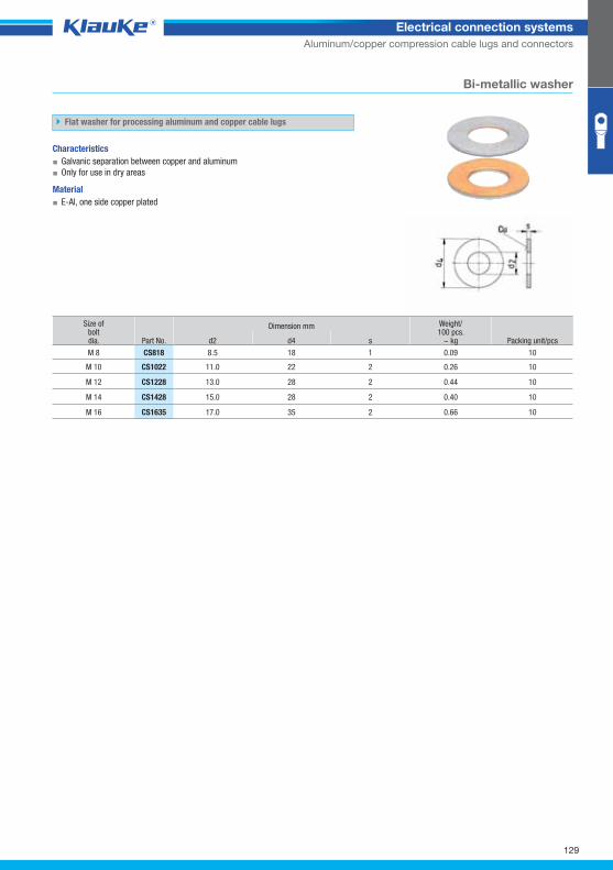
cs818grp
129
Electrical connection systems
Aluminum/copper compression cable lugs and connectors
Bi-metallic washer
Flat washer for processing aluminum and copper cable lugs
Characteristics
▪ Galvanic separation between copper and aluminum
▪ Only for use in dry areas
Material
▪ E-Al, one side copper plated
Size ofboltdia. Part No.
Dimension mm Weight/100 pcs.
~ kg Packing unit/pcs d2 d4 s
M 8 CS818 8.5 18 1 0.09 10
M 10 CS1022 11.0 22 2 0.26 10
M 12 CS1228 13.0 28 2 0.44 10
M 14 CS1428 15.0 28 2 0.40 10
M 16 CS1635 17.0 35 2 0.66 10
Klauke Hauptkatalog EN_DIN A5.indb 129 07.10.2014 12:17:03
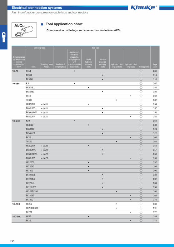
130
Electrical connection systems
Aluminum/copper compression cable lugs and connectors
^WZT_PV_AlCu^ � Tool application chart
Compression cable lugs and connectors made from Al/Cu
Crimping tools Tool type
Crimping rangecorresponds to
nominalcross-section
mm² ToolsCrimping head/
AdapterMechanical
crimping tools
mechanical,electrical,
pneumatic, crimping tools
with interchangeable
dies/heads
Handhydraulic crimping
tools
Batterypowered crimping
toolsHydraulic crim-ping systems
Hydraulic crim-ping heads Crimp profile
Page(Tool)
K354 • 260
EK354 • 314
EK354L • 316
10-70
K18 • 262
HK6018 • 286
EK5018L • 320
PK18 • 362
THK18 • 362
HK60UNV + UA18 • 354
EK60UNVL + UA18 • 357
EKM60UNVL + UA18 • 356
PK60UNV + UA18 • 355
10-185
K22 • 264
HK6022 • 288
EK6022L • 324
EKM6022L • 322
PK22 • 364
THK22 • 364
HK60UNV + UA22 • 354
EK60UNVL + UA22 • 357
EKM60UNVL + UA22 • 356
PK60UNV + UA22 • 355
HK12030 • 292
HK12042 • 294
HK120U • 296
EK12030L • 330
EK12042L • 332
EK120UL • 334
EK120UNVL • 358
HK122EL380 • 390
PK12042 • 368
PK120U • 370
10-240
HK252 • 388
HK252EL380 • 391
PK252 • 372
10-500
HK45 • 389
PK45 • 374
150-500
Klauke Hauptkatalog EN_DIN A5.indb 130 07.10.2014 12:17:03

131
Electrical connection systems
Aluminum/copper compression cable lugs and connectors
Klauke Hauptkatalog EN_DIN A5.indb 131 07.10.2014 12:17:04
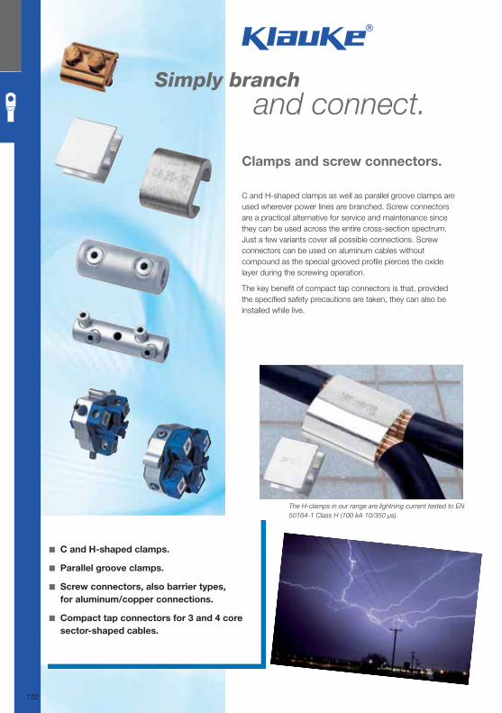
Simply branch and connect.
Clamps and screw connectors.
◾ C and H-shaped clamps.
◾ Parallel groove clamps.
◾ Screw connectors, also barrier types,
for aluminum/copper connections.
◾ Compact tap connectors for 3 and 4 core
sector-shaped cables.
The H-clamps in our range are lightning current tested to EN
50164-1 Class H (100 kA 10/350 μs).
C and H-shaped clamps as well as parallel groove clamps are used wherever power lines are branched. Screw connectors are a practical alternative for service and maintenance since they can be used across the entire cross-section spectrum. Just a few variants cover all possible connections. Screw connectors can be used on aluminum cables without compound as the special grooved profi le pierces the oxide layer during the screwing operation.
The key benefi t of compact tap connectors is that, provided the specifi ed safety precautions are taken, they can also be installed while live.
132
Klauke Hauptkatalog EN_DIN A5.indb 132 07.10.2014 12:17:04
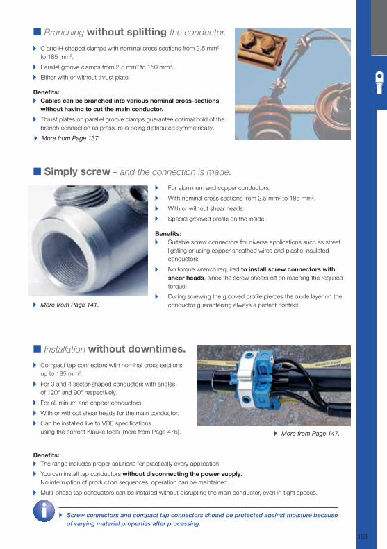
■ Branching without splitting the conductor. ▸ C and H-shaped clamps with nominal cross sections from 2.5 mm2
to 185 mm2.
▸ Parallel groove clamps from 2.5 mm² to 150 mm².
▸ Either with or without thrust plate.
Benefi ts: ▸ Cables can be branched into various nominal cross-sections
without having to cut the main conductor.
▸ Thrust plates on parallel groove clamps guarantee optimal hold of the
branch connection as pressure is being distributed symmetrically.
■ Installation without downtimes.
▸ Compact tap connectors with nominal cross sections
up to 185 mm2.
▸ For 3 and 4 sector-shaped conductors with angles
of 120° and 90° respectively.
▸ For aluminum and copper conductors.
▸ With or without shear heads for the main conductor.
▸ Can be installed live to VDE specifi cations
using the correct Klauke tools (more from Page 476).
Benefi ts: ▸ The range includes proper solutions for practically every application.
▸ You can install tap conductors without disconnecting the power supply.
No interruption of production sequences, operation can be maintained.
▸ Multi-phase tap conductors can be installed without disrupting the main conductor, even in tight spaces.
▸ More from Page 137.
▸ Screw connectors and compact tap connectors should be protected against moisture because of varying material properties after processing.
■ Simply screw – and the connection is made.
▸ For aluminum and copper conductors.
▸ With nominal cross sections from 2.5 mm2 to 185 mm2.
▸ With or without shear heads.
▸ Special grooved profi le on the inside.
Benefi ts: ▸ Suitable screw connectors for diverse applications such as street
lighting or using copper sheathed wires and plastic-insulated
conductors.
▸ No torque wrench required to install screw connectors with
shear heads, since the screw shears off on reaching the required
torque.
▸ During screwing the grooved profi le pierces the oxide layer on the
conductor guaranteeing always a perfect contact. ▸ More from Page 141.
▸ More from Page 147.
133
Klauke Hauptkatalog EN_DIN A5.indb 133 07.10.2014 12:17:05
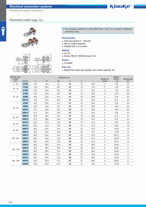
572r6grp
134
Electrical connection systems
Clamps and screw connectors
Punched cable lugs, Cu
For screwing conductors to VDE 0295 Class 1 and 2, for example in lightning
protection areas
Characteristics
▪ Total cross-section: 6 - 300 mm²
▪ Also for outdoor assembly
▪ Available with 2 or 4 screws
Material
▪ Cu-ETP
▪ Screws: DIN 84 / DIN 933 bronze, F 60
Surface
▪ Tin-plated
Order info
▪ Bright finish version also available, part number appendix "bk"
Nominal cross section mm² Part No.
Dimension mm Number of
screws
Weight/100 pcs.
~ kg Packing unit/
pcs b b1 d2 k h l
6 - 10 572R6 15.0 18.0 6.5 M4 10 23.0 2 1.30 50
10 - 16 573R6 15.0 20.5 6.5 M5 14 27.0 2 1.30 50
573R8 15.0 20.5 8.5 M5 14 27.0 2 1.30 50
16 - 25
574R8 15.0 25.0 8.5 M5 16 30.0 2 2.75 50
584R8 18.5 22.5 8.5 M5 16 36.0 4 3.70 25
584R10 19.5 22.5 10.5 M5 16 37.0 4 3.75 25
25 - 35
575R8 18.5 24.0 8.5 M5 16 25.5 2 2.50 50
585R8 18.5 24.0 8.5 M5 16 38.5 4 4.30 25
585R10 21.5 24.0 10.5 M5 16 42.0 4 4.65 25
585R12 21.5 24.0 13.0 M5 16 42.0 4 4.50 25
35 - 50 586R10 19.0 28.0 10.5 M6 19 46.0 4 6.75 25
586R12 21.0 28.0 13.0 M6 19 47.0 4 6.70 25
50 - 70 587R10 23.5 31.0 10.5 M6 19 51.0 4 9.35 10
587R12 23.5 31.0 13.0 M6 19 51.0 4 9.30 10
70 - 95 588R10 24.0 34.0 10.5 M6 25 57.0 4 12.00 10
588R12 24.0 34.0 13.0 M6 25 57.0 4 11.85 10
95 - 150
589R10 30.0 42.0 10.5 M8 32 61.0 4 20.15 10
589R12 30.0 42.0 13.0 M8 32 61.0 4 20.20 10
589R16 30.0 42.0 17.0 M8 32 61.5 4 20.10 10
150 - 240
590R10 34.0 48.5 10.5 M8 32 68.5 4 24.40 5
590R12 34.0 48.5 13.0 M8 32 68.5 4 24.35 5
590R16 34.0 48.5 17.0 M8 32 68.5 4 24.30 5
590R20 36.0 48.5 21.0 M8 32 70.5 4 24.25 5
185 - 300
592R12 32.0 50.0 13.0 M8 37 68.5 4 27.95 5
592R16 32.0 50.0 17.0 M8 37 68.5 4 28.00 5
592R20 34.5 50.5 21.0 M8 37 70.0 4 27.95 5
Klauke Hauptkatalog EN_DIN A5.indb 134 07.10.2014 12:17:06
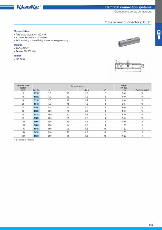
551rgrp
135
Electrical connection systems
Clamps and screw connectors
Tube screw connectors, CuZn
Characteristics
▪ Total cross-section: 6 - 300 mm²
▪ A connection needs to be soldered
▪ With soldering hole and fixing screws for easy processing
Material
▪ CuZn 40 Pb 2
▪ Screws: DIN 551 steel
Surface
▪ Tin-plated
Nominal cross section mm² Part No.
Dimension mm Weight/100 pcs.
~ kg Packing unit/pcs d1 l dia. q z*
6 551R 3.5 25 3.3 2 0.60 10
10 552R 4.5 30 3.3 2 1.20 10
16 553R 5.5 40 4.2 4 1.90 10
25 554R 7.0 45 4.2 4 2.85 10
35 555R 8.5 45 5.0 4 3.00 10
50 556R 10.0 48 5.0 4 4.00 10
70 557R 12.0 52 6.8 4 6.30 10
95 558R 13.5 55 6.8 4 8.05 10
120 559R 15.0 60 6.8 4 9.90 10
150 560R 17.0 64 6.8 4 11.80 5
185 561R 19.0 70 6.8 10 14.30 5
240 562R 21.0 70 6.8 10 15.50 5
300 563R 24.0 75 6.8 10 19.30 1
z = number of set screws
Klauke Hauptkatalog EN_DIN A5.indb 135 07.10.2014 12:17:07
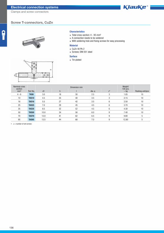
tas6grp
136
Electrical connection systems
Clamps and screw connectors
Screw T-connectors, CuZn
Characteristics
▪ Total cross-section: 4 - 95 mm²
▪ A connection needs to be soldered
▪ With soldering hole and fixing screws for easy processing
Material
▪ CuZn 40 Pb 2
▪ Screws: DIN 551 steel
Surface
▪ Tin-plated
Nominal cross section mm² Part No.
Dimension mm Weight/100 pcs.
~ kg Packing unit/pcs d1 h l dia. q z*
4 - 6 TAS6 3.0 18 30 2.5 3 1.05 10
10 TAS10 4.5 25 40 3.5 3 2.15 10
16 TAS16 5.5 27 42 3.5 6 2.50 10
25 TAS25 7.0 29 45 4.5 6 3.70 10
35 TAS35 8.5 32 52 4.5 6 4.30 10
50 TAS50 10.0 34 56 6.0 9 7.40 10
70 TAS70 12.0 41 62 6.5 9 9.80 5
95 TAS95 13.5 44 68 7.0 9 12.80 5
z = number of set screws
Klauke Hauptkatalog EN_DIN A5.indb 136 07.10.2014 12:17:07
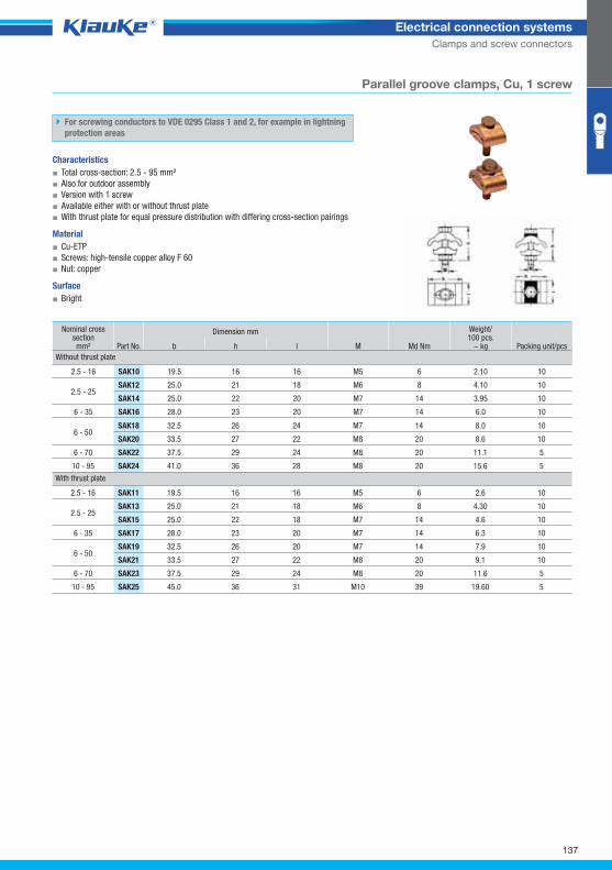
SAK_GRP01
137
Electrical connection systems
Clamps and screw connectors
Parallel groove clamps, Cu, 1 screw
For screwing conductors to VDE 0295 Class 1 and 2, for example in lightning
protection areas
Characteristics
▪ Total cross-section: 2.5 - 95 mm²
▪ Also for outdoor assembly
▪ Version with 1 screw
▪ Available either with or without thrust plate
▪ With thrust plate for equal pressure distribution with differing cross-section pairings
Material
▪ Cu-ETP
▪ Screws: high-tensile copper alloy F 60
▪ Nut: copper
Surface
▪ Bright
Nominal cross section mm² Part No.
Dimension mm
M Md Nm
Weight/100 pcs.
~ kg Packing unit/pcs b h l
Without thrust plate
2.5 - 16 SAK10 19.5 16 16 M5 6 2.10 10
2.5 - 25 SAK12 25.0 21 18 M6 8 4.10 10
SAK14 25.0 22 20 M7 14 3.95 10
6 - 35 SAK16 28.0 23 20 M7 14 6.0 10
6 - 50 SAK18 32.5 26 24 M7 14 8.0 10
SAK20 33.5 27 22 M8 20 8.6 10
6 - 70 SAK22 37.5 29 24 M8 20 11.1 5
10 - 95 SAK24 41.0 36 28 M8 20 15.6 5
With thrust plate
2.5 - 16 SAK11 19.5 16 16 M5 6 2.6 10
2.5 - 25 SAK13 25.0 21 18 M6 8 4.30 10
SAK15 25.0 22 18 M7 14 4.6 10
6 - 35 SAK17 28.0 23 20 M7 14 6.3 10
6 - 50 SAK19 32.5 26 20 M7 14 7.9 10
SAK21 33.5 27 22 M8 20 9.1 10
6 - 70 SAK23 37.5 29 24 M8 20 11.6 5
10 - 95 SAK25 45.0 36 31 M10 39 19.60 5
Klauke Hauptkatalog EN_DIN A5.indb 137 07.10.2014 12:17:07
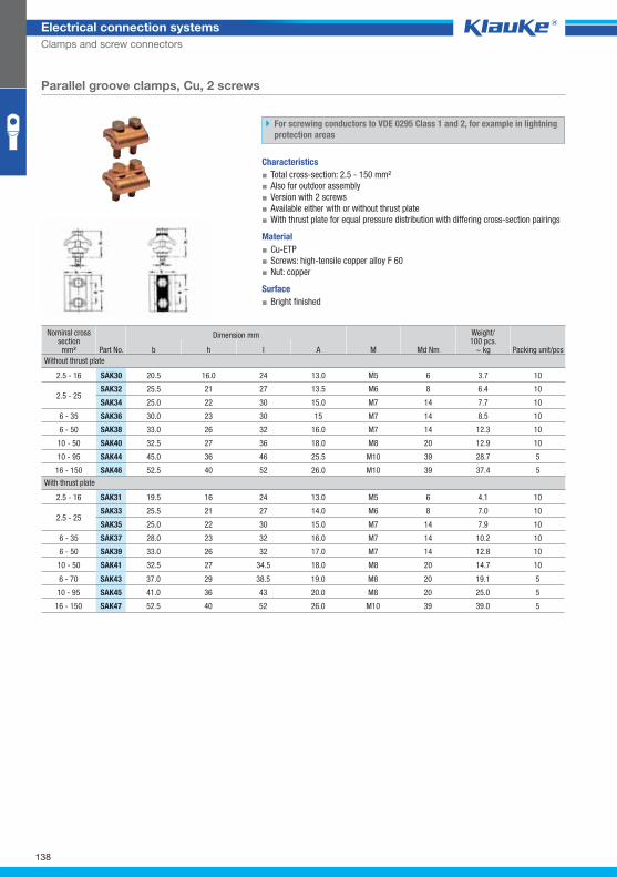
SAK_GRP02
138
Electrical connection systems
Clamps and screw connectors
Parallel groove clamps, Cu, 2 screws
For screwing conductors to VDE 0295 Class 1 and 2, for example in lightning
protection areas
Characteristics
▪ Total cross-section: 2.5 - 150 mm²
▪ Also for outdoor assembly
▪ Version with 2 screws
▪ Available either with or without thrust plate
▪ With thrust plate for equal pressure distribution with differing cross-section pairings
Material
▪ Cu-ETP
▪ Screws: high-tensile copper alloy F 60
▪ Nut: copper
Surface
▪ Bright finished
Nominal cross section mm² Part No.
Dimension mm
M Md Nm
Weight/100 pcs.
~ kg Packing unit/pcs b h l A
Without thrust plate
2.5 - 16 SAK30 20.5 16.0 24 13.0 M5 6 3.7 10
2.5 - 25 SAK32 25.5 21 27 13.5 M6 8 6.4 10
SAK34 25.0 22 30 15.0 M7 14 7.7 10
6 - 35 SAK36 30.0 23 30 15 M7 14 8.5 10
6 - 50 SAK38 33.0 26 32 16.0 M7 14 12.3 10
10 - 50 SAK40 32.5 27 36 18.0 M8 20 12.9 10
10 - 95 SAK44 45.0 36 46 25.5 M10 39 28.7 5
16 - 150 SAK46 52.5 40 52 26.0 M10 39 37.4 5
With thrust plate
2.5 - 16 SAK31 19.5 16 24 13.0 M5 6 4.1 10
2.5 - 25 SAK33 25.5 21 27 14.0 M6 8 7.0 10
SAK35 25.0 22 30 15.0 M7 14 7.9 10
6 - 35 SAK37 28.0 23 32 16.0 M7 14 10.2 10
6 - 50 SAK39 33.0 26 32 17.0 M7 14 12.8 10
10 - 50 SAK41 32.5 27 34.5 18.0 M8 20 14.7 10
6 - 70 SAK43 37.0 29 38.5 19.0 M8 20 19.1 5
10 - 95 SAK45 41.0 36 43 20.0 M8 20 25.0 5
16 - 150 SAK47 52.5 40 52 26.0 M10 39 39.0 5
Klauke Hauptkatalog EN_DIN A5.indb 138 07.10.2014 12:17:08
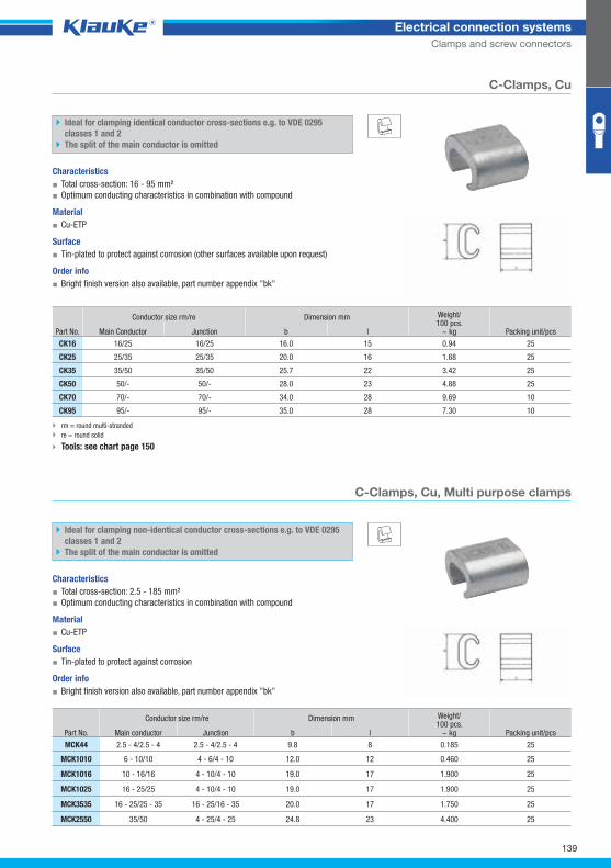
ck16grp
mck44grp
139
Electrical connection systems
Clamps and screw connectors
C-Clamps, Cu
Ideal for clamping identical conductor cross-sections e.g. to VDE 0295
classes 1 and 2
The split of the main conductor is omitted
Characteristics
▪ Total cross-section: 16 - 95 mm²
▪ Optimum conducting characteristics in combination with compound
Material
▪ Cu-ETP
Surface
▪ Tin-plated to protect against corrosion (other surfaces available upon request)
Order info
▪ Bright finish version also available, part number appendix "bk"
Part No.
Conductor size rm/re Dimension mm Weight/100 pcs.
~ kg Packing unit/pcs Main Conductor Junction b l
CK16 16/25 16/25 16.0 15 0.94 25
CK25 25/35 25/35 20.0 16 1.68 25
CK35 35/50 35/50 25.7 22 3.42 25
CK50 50/- 50/- 28.0 23 4.88 25
CK70 70/- 70/- 34.0 28 9.69 10
CK95 95/- 95/- 35.0 28 7.30 10
rm = round multi-stranded
re = round solid
Tools: see chart page 150
C-Clamps, Cu, Multi purpose clamps
Ideal for clamping non-identical conductor cross-sections e.g. to VDE 0295
classes 1 and 2
The split of the main conductor is omitted
Characteristics
▪ Total cross-section: 2.5 - 185 mm²
▪ Optimum conducting characteristics in combination with compound
Material
▪ Cu-ETP
Surface
▪ Tin-plated to protect against corrosion
Order info
▪ Bright finish version also available, part number appendix "bk"
Part No.
Conductor size rm/re Dimension mm Weight/100 pcs.
~ kg Packing unit/pcs Main conductor Junction b l
MCK44 2.5 - 4/2.5 - 4 2.5 - 4/2.5 - 4 9.8 8 0.185 25
MCK1010 6 - 10/10 4 - 6/4 - 10 12.0 12 0.460 25
MCK1016 10 - 16/16 4 - 10/4 - 10 19.0 17 1.900 25
MCK1025 16 - 25/25 4 - 10/4 - 10 19.0 17 1.900 25
MCK3535 16 - 25/25 - 35 16 - 25/16 - 35 20.0 17 1.750 25
MCK2550 35/50 4 - 25/4 - 25 24.8 23 4.400 25
Klauke Hauptkatalog EN_DIN A5.indb 139 07.10.2014 12:17:08
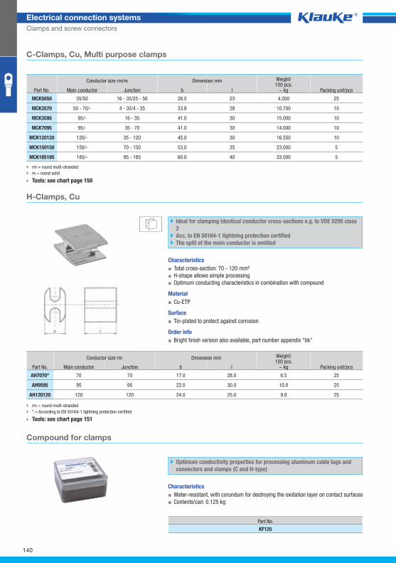
ah7070grp
kf125grp
140
Electrical connection systems
Clamps and screw connectors
rm = round multi-stranded
re = round solid
Tools: see chart page 150
H-Clamps, Cu
Ideal for clamping identical conductor cross-sections e.g. to VDE 0295 class
2
Acc. to EN 50164-1 lightning protection certified
The split of the main conductor is omitted
Characteristics
▪ Total cross-section: 70 - 120 mm²
▪ H-shape allows simple processing
▪ Optimum conducting characteristics in combination with compound
Material
▪ Cu-ETP
Surface
▪ Tin-plated to protect against corrosion
Order info
▪ Bright finish version also available, part number appendix "bk"
Part No.
Conductor size rm Dimension mm Weight/100 pcs.
~ kg Packing unit/pcs Main conductor Junction b l
AH7070* 70 70 17.0 28.0 6.5 25
AH9595 95 95 22.0 30.0 10.0 25
AH120120 120 120 24.0 25.0 9.8 25
rm = round multi-stranded
* = According to EN 50164-1 lightning protection certified
Tools: see chart page 151
Compound for clamps
Optimum conductivity properties for processing aluminum cable lugs and
connectors and clamps (C and H-type)
Characteristics
▪ Water-resistant, with corundum for destroying the oxidation layer on contact surfaces
▪ Contents/can: 0.125 kg
Part No.
KF125
mck44grp C-Clamps, Cu, Multi purpose clamps
Part No.
Conductor size rm/re Dimension mm Weight/100 pcs.
~ kg Packing unit/pcs Main conductor Junction b l
MCK5050 35/50 16 - 35/25 - 50 26.5 23 4.200 25
MCK3570 50 - 70/- 4 - 35/4 - 35 33.8 28 10.700 10
MCK3595 95/- 16 - 35 41.0 30 15.000 10
MCK7095 95/- 35 - 70 41.0 30 14.000 10
MCK120120 120/- 35 - 120 45.0 30 16.550 10
MCK150150 150/- 70 - 150 53.0 35 23.000 5
MCK185185 185/- 95 - 185 60.0 40 33.000 5
Klauke Hauptkatalog EN_DIN A5.indb 140 07.10.2014 12:17:09
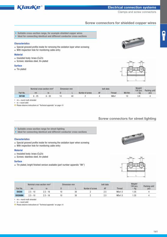
sv100grp
sv200grp
141
Electrical connection systems
Clamps and screw connectors
Screw connectors for shielded copper wires
Suitable cross-section range, for example shielded copper wires
Ideal for connecting identical and different conductor cross-sections
Characteristics
▪ Special grooved profile inside for removing the oxidation layer when screwing
▪ With inspection hole for monitoring cable entry
Material
▪ Insulated body: brass (CuZn)
▪ Screws: stainless steel, tin-plated
Surface
▪ Tin-plated
Part No.
Nominal cross section mm² Dimension mm bolt data Weight/100 pcs.
~ kg Packing unit/
pcs rm re D L Number of screws AF Thread Md Nm
SV100 6 - 25 6 - 35 14 40 2 4 M8x1 10 3.9 4
rm = round multi-stranded
re = round solid
Please observe instructions at "Technical appendix" on page i-9
Screw connectors for street lighting
Suitable cross-section range for street lighting
Ideal for connecting identical and different conductor cross-sections
Characteristics
▪ Special grooved profile inside for removing the oxidation layer when screwing
▪ With inspection hole for monitoring cable entry
Material
▪ Insulated body: brass (CuZn)
▪ Screws: stainless steel, tin-plated
Surface
▪ Tin-plated, bright finished version available (part number appendix "BK")
Nominal cross section mm² Dimension mm bolt data Weight/100 pcs.
~ kg Packing unit/
pcs Part No. rm re D L Number of screws AF Thread
SV200 2.5 - 10 2.5 - 16 10 30 2 2.5 M5x1.5 1.35 4
SV200BK 2.5 - 10 2.5 - 16 10 30 2 2.5 M5x1.5 1.35 4
rm = round multi-stranded
re = round solid
Please observe instructions at "Technical appendix" on page i-9
Klauke Hauptkatalog EN_DIN A5.indb 141 07.10.2014 12:17:09
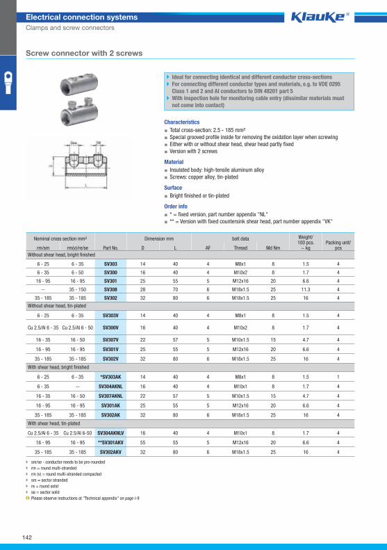
SV303_GRP01
142
Electrical connection systems
Clamps and screw connectors
Screw connector with 2 screws
Ideal for connecting identical and different conductor cross-sections
For connecting different conductor types and materials, e.g. to VDE 0295
Class 1 and 2 and Al conductors to DIN 48201 part 5
With inspection hole for monitoring cable entry (dissimilar materials must
not come into contact)
Characteristics
▪ Total cross-section: 2.5 - 185 mm²
▪ Special grooved profile inside for removing the oxidation layer when screwing
▪ Either with or without shear head, shear head partly fixed
▪ Version with 2 screws
Material
▪ Insulated body: high-tensile aluminum alloy
▪ Screws: copper alloy, tin-plated
Surface
▪ Bright finished or tin-plated
Order info
▪ * = fixed version, part number appendix "NL"
▪ ** = Version with fixed countersink shear head, part number appendix "VK"
Nominal cross section mm²
Part No.
Dimension mm bolt data Weight/100 pcs.
~ kg Packing unit/
pcs rm/sm rm(v)/re/se D L AF Thread Md Nm
Without shear head, bright finished
6 - 25 6 - 35 SV303 14 40 4 M8x1 8 1.5 4
6 - 35 6 - 50 SV300 16 40 4 M10x2 8 1.7 4
16 - 95 16 - 95 SV301 25 55 5 M12x16 20 6.6 4
-- 35 - 150 SV308 28 70 6 M18x1.5 25 11.3 4
35 - 185 35 - 185 SV302 32 80 6 M18x1.5 25 16 4
Without shear head, tin-plated
6 - 25 6 - 35 SV303V 14 40 4 M8x1 8 1.5 4
Cu 2.5/Al 6 - 35 Cu 2.5/Al 6 - 50 SV300V 16 40 4 M10x2 8 1.7 4
16 - 35 16 - 50 SV307V 22 57 5 M10x1.5 15 4.7 4
16 - 95 16 - 95 SV301V 25 55 5 M12x16 20 6.6 4
35 - 185 35 - 185 SV302V 32 80 6 M18x1.5 25 16 4
With shear head, bright finished
6 - 25 6 - 35 *SV303AK 14 40 4 M8x1 8 1.5 1
6 - 35 -- SV304AKNL 16 40 4 M10x1 8 1.7 4
16 - 35 16 - 50 SV307AKNL 22 57 5 M10x1.5 15 4.7 4
16 - 95 16 - 95 SV301AK 25 55 5 M12x16 20 6.6 4
35 - 185 35 - 185 SV302AK 32 80 6 M18x1.5 25 16 4
With shear head, tin-plated
Cu 2.5/Al 6 - 35 Cu 2.5/Al 6-50 SV304AKNLV 16 40 4 M10x1 8 1.7 4
16 - 95 16 - 95 **SV301AKV 55 55 5 M12x16 20 6.6 4
35 - 185 35 - 185 SV302AKV 32 80 6 M18x1.5 25 16 4
sm/se - conductor needs to be pre-rounded
rm = round multi-stranded
rm (v) = round multi-stranded compacted
sm = sector stranded
re = round solid
se = sector solid
Please observe instructions at "Technical appendix" on page i-9
Klauke Hauptkatalog EN_DIN A5.indb 142 07.10.2014 12:17:10
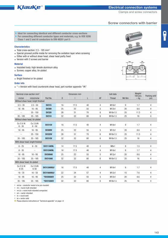
SV315_GRP02
143
Electrical connection systems
Clamps and screw connectors
Screw connectors with barrier
Ideal for connecting identical and different conductor cross-sections
For connecting different conductor types and materials, e.g. to VDE 0295
Class 1 and 2 and Al conductors to DIN 48201 part 5
Characteristics
▪ Total cross-section: 2.5 - 185 mm²
▪ Special grooved profile inside for removing the oxidation layer when screwing
▪ Either with or without shear head, shear head partly fixed
▪ Version with 2 screws and barrier
Material
▪ Insulated body: high-tensile aluminum alloy
▪ Screws: copper alloy, tin-plated
Surface
▪ Bright finished or tin-plated
Order info
▪ * = Version with fixed countersink shear head, part number appendix "VK"
Nominal cross section mm²
Part No.
Dimension mm bolt data Weight/100 pcs.
~ kg Packing unit/
pcs rm/sm rm(v)/re/se D l L AF Thread Md Nm
Without shear head, bright finished
2.5 - 35 2.5 - 50 SV315 16 17.5 40 4 M10x1 9 1.7 4
16 - 95 16 - 95 SV309 25 22 55 5 M12x1 20 6.6 4
-- 35 - 150 SV320 28 31 70 6 M18x1.5 25 11.3 4
35 - 185 35 - 185 SV310 32 32 80 6 M18x1.5 25 16 4
Without shear head, tin-plated
Cu 2.5/ Al
6 - 35
Cu 2.5/Al
6 - 50 SV315V 16 17.5 40 4 M10x1 9 1.7 4
16 - 95 16 - 95 SV309V 25 22 55 5 M12x1 20 6.6 4
-- 35 - 150 SV320V 28 31 70 6 M18x1.5 25 11.3 4
35 - 185 35 - 185 SV310V 32 32 80 6 M18x1.5 25 16 4
With shear head, bright finished
6 - 25 6 - 35 SV311AKNL 14 17.5 40 4 M8x1 8 1.5 4
6 - 35 -- SV312AKNL 16 17.5 40 4 M10x1 8 1.7 4
16 - 95 16 - 95 SV309AK 25 22 55 5 M12x1 20 6.6 4
35 - 185 35 - 185 SV310AK 32 32 80 6 M18x1.5 25 16 4
With shear head, tin-plated
Cu 2.5/ Al
6-35
Cu 2.5/Al
6-50 SV312AKNLV 16 17.5 40 4 M10x1 8 1.7 4
16 - 35 16 - 50 SV319AKNLV 22 24 57 4 M12x1 15 7.6 4
16 - 95 16 - 95 *SV309AKV 25 22 55 5 M12x1 20 6.6 4
35 - 185 35 - 185 *SV310AKV 32 32 80 6 M18x1.5 25 16 4
sm/se - conductor needs to be pre-rounded
rm = round multi-stranded
rm (v) = round multi-stranded compacted
sm = sector stranded
re = round solid
se = sector solid
Please observe instructions at "Technical appendix" on page i-9
Klauke Hauptkatalog EN_DIN A5.indb 143 07.10.2014 12:17:10
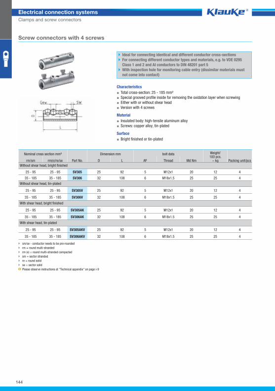
SV305_GRP03
144
Electrical connection systems
Clamps and screw connectors
Screw connectors with 4 screws
Ideal for connecting identical and different conductor cross-sections
For connecting different conductor types and materials, e.g. to VDE 0295
Class 1 and 2 and Al conductors to DIN 48201 part 5
With inspection hole for monitoring cable entry (dissimilar materials must
not come into contact)
Characteristics
▪ Total cross-section: 25 - 185 mm²
▪ Special grooved profile inside for removing the oxidation layer when screwing
▪ Either with or without shear head
▪ Version with 4 screws
Material
▪ Insulated body: high-tensile aluminum alloy
▪ Screws: copper alloy, tin-plated
Surface
▪ Bright finished or tin-plated
Nominal cross section mm²
Part No.
Dimension mm bolt data Weight/100 pcs.
~ kg Packing unit/pcs rm/sm rm(v)/re/se D L AF Thread Md Nm
Without shear head, bright finished
25 - 95 25 - 95 SV305 25 92 5 M12x1 20 12 4
35 - 185 35 - 185 SV306 32 108 6 M18x1.5 25 25 4
Without shear head, tin-plated
25 - 95 25 - 95 SV305V 25 92 5 M12x1 20 12 4
35 - 185 35 - 185 SV306V 32 108 6 M18x1.5 25 25 4
With shear head, bright finished
25 - 95 25 - 95 SV305AK 25 92 5 M12x1 20 12 4
35 - 185 35 - 185 SV306AK 32 108 6 M18x1.5 25 25 4
With shear head, tin-plated
25 - 95 25 - 95 SV305AKV 25 92 5 M12x1 20 12 4
35 - 185 35 - 185 SV306AKV 32 108 6 M18x1.5 25 25 4
sm/se - conductor needs to be pre-rounded
rm = round multi-stranded
rm (v) = round multi-stranded compacted
sm = sector stranded
re = round solid
se = sector solid
Please observe instructions at "Technical appendix" on page i-9
Klauke Hauptkatalog EN_DIN A5.indb 144 07.10.2014 12:17:10
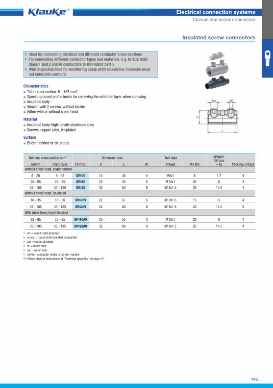
SV400_GRP04
145
Electrical connection systems
Clamps and screw connectors
Insulated screw connectors
Ideal for connecting identical and different conductor cross-sections
For connecting different conductor types and materials, e.g. to VDE 0295
Class 1 and 2 and Al conductors to DIN 48201 part 5
With inspection hole for monitoring cable entry (dissimilar materials must
not come into contact)
Characteristics
▪ Total cross-section: 6 - 185 mm²
▪ Special grooved profile inside for removing the oxidation layer when screwing
▪ Insulated body
▪ Version with 2 screws, without barrier
▪ Either with or without shear head
Material
▪ Insulated body: high-tensile aluminum alloy
▪ Screws: copper alloy, tin-plated
Surface
▪ Bright finished or tin-plated
Nominal cross section mm²
Part No.
Dimension mm bolt data Weight/100 pcs.
~ kg Packing unit/pcs rm/sm rm(v)/re/se D L AF Thread Md Nm
Without shear head, bright finished
6 - 25 6 - 35 SV400 14 40 4 M8x1 8 1.7 4
25 - 95 25 - 95 SV410 25 55 5 M12x1 20 6 4
35 - 185 35 - 185 SV420 32 80 6 M18x1.5 25 14.5 4
Without shear head, tin-plated
16 - 35 16 - 50 SV405V 22 57 5 M10x1.5 15 5 4
35 - 185 35 - 185 SV420V 32 80 6 M18x1.5 25 14.5 4
With shear head, bright finished
25 - 95 25 - 95 SV410AK 25 55 5 M12x1 20 6 4
35 - 185 35 - 185 SV420AK 32 80 6 M18x1.5 25 14.5 4
rm = round multi-stranded
rm (v) = round multi-stranded compacted
sm = sector stranded
re = round solid
se = sector solid
sm/se - conductor needs to be pre-rounded
Please observe instructions at "Technical appendix" on page i-9
Klauke Hauptkatalog EN_DIN A5.indb 145 07.10.2014 12:17:11
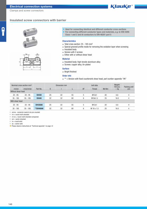
SV430_GRP05
146
Electrical connection systems
Clamps and screw connectors
Insulated screw connectors with barrier
Ideal for connecting identical and different conductor cross-sections
For connecting different conductor types and materials, e.g. to VDE 0295
Class 1 and 2 and Al conductors to DIN 48201 part 5
Characteristics
▪ Total cross-section: 25 - 185 mm²
▪ Special grooved profile inside for removing the oxidation layer when screwing
▪ Insulated body
▪ Version with 2 screws
▪ Either with or without shear head
Material
▪ Insulated body: high-tensile aluminum alloy
▪ Screws: copper alloy, tin-plated
Surface
▪ Bright finished
Order info
▪ ** = Version with fixed countersink shear head, part number appendix "VK"
Nominal cross section mm² Dimension mm bolt data Weight/100 pcs.
~ kg Packing unit/
pcs rm/sm rm(v)/re/se Part No. D l L AF Thread Md Nm
Without shear head
25 - 95 25 - 95 SV430 25 22 55 5 M12x1 20 6.6 4
35 - 185 35 - 185 SV440 32 32 80 6 M18x1.5 25 16.0 4
With shear head
25 - 95 25 - 95 SV430AK 25 22 55 5 M12x1 20 6.6 4
35 - 185 35 - 185 **SV440AK 32 32 80 6 M 18 x 1.5 25 16.0 4
sm/se - conductor needs to be pre-rounded
rm = round multi-stranded
rm (v) = round multi-stranded compacted
sm = sector stranded
re = round solid
se = sector solid
Please observe instructions at "Technical appendix" on page i-9
Klauke Hauptkatalog EN_DIN A5.indb 146 07.10.2014 12:17:11
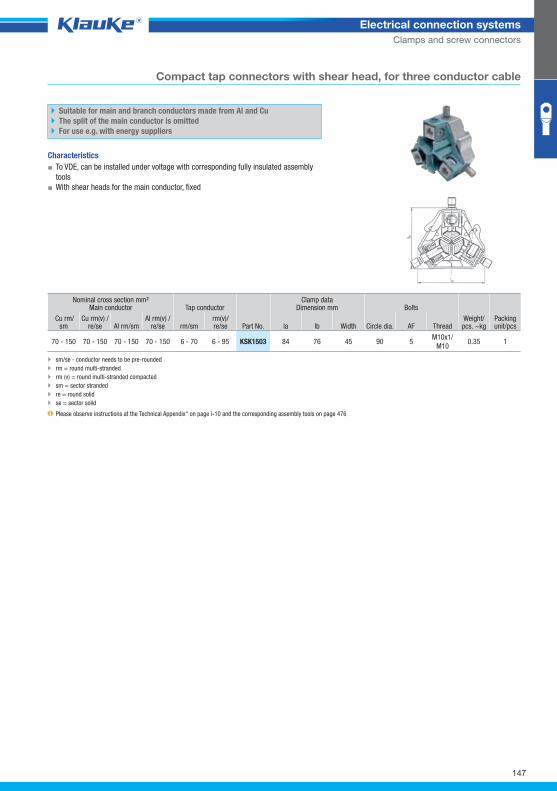
147
Electrical connection systems
Clamps and screw connectors
ksk1503grp Compact tap connectors with shear head, for three conductor cable
Suitable for main and branch conductors made from Al and Cu
The split of the main conductor is omitted
For use e.g. with energy suppliers
Characteristics
▪ To VDE, can be installed under voltage with corresponding fully insulated assembly
tools
▪ With shear heads for the main conductor, fixed
Nominal cross section mm² Main conductor Tap conductor
Part No.
Clamp dataDimension mm Bolts
Weight/pcs. ~kg
Packing unit/pcs
Cu rm/sm
Cu rm(v) /re/se Al rm/sm
Al rm(v) /re/se rm/sm
rm(v)/re/se la lb Width Circle dia. AF Thread
70 - 150 70 - 150 70 - 150 70 - 150 6 - 70 6 - 95 KSK1503 84 76 45 90 5 M10x1/
M10 0.35 1
sm/se - conductor needs to be pre-rounded
rm = round multi-stranded
rm (v) = round multi-stranded compacted
sm = sector stranded
re = round solid
se = sector solid
Please observe instructions at the Technical Appendix" on page i-10 and the corresponding assembly tools on page 476
Klauke Hauptkatalog EN_DIN A5.indb 147 07.10.2014 12:17:12
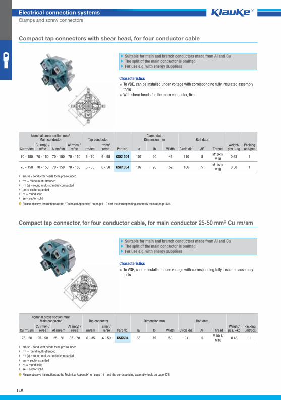
148
Electrical connection systems
Clamps and screw connectors
ksk504grp Compact tap connector, for four conductor cable, for main conductor 25-50 mm² Cu rm/sm
Suitable for main and branch conductors made from Al and Cu
The split of the main conductor is omitted
For use e.g. with energy suppliers
Characteristics
▪ To VDE, can be installed under voltage with corresponding fully insulated assembly
tools
Nominal cross section mm²Main conductor Tap conductor Dimension mm Bolt data
Cu rm/sm Cu rm(v) /
re/se Al rm/sm Al rm(v) /
re/se rm/sm rm(v)/re/se Part No. la lb Width Circle dia. AF Thread
Weight/pcs. ~kg
Packing unit/pcs
25 - 50 25 - 50 25 - 50 35 - 70 6 - 35 6 - 50 KSK504 88 75 50 91 5 M10x1/
M10 0.46 1
sm/se - conductor needs to be pre-rounded
rm = round multi-stranded
rm (v) = round multi-stranded compacted
sm = sector stranded
re = round solid
se = sector solid
Please observe instructions at the Technical Appendix" on page i-11 and the corresponding assembly tools on page 476
ksk1504grp Compact tap connectors with shear head, for four conductor cable
Suitable for main and branch conductors made from Al and Cu
The split of the main conductor is omitted
For use e.g. with energy suppliers
Characteristics
▪ To VDE, can be installed under voltage with corresponding fully insulated assembly
tools
▪ With shear heads for the main conductor, fixed
Nominal cross section mm²Main conductor Tap conductor
Clamp data Dimension mm Bolt data
Weight/pcs. ~kg
Packing unit/pcs Cu rm/sm
Cu rm(v) /re/se Al rm/sm
Al rm(v) /re/se rm/sm
rm(v)/re/se Part No. la lb Width Circle dia. AF Thread
70 - 150 70 - 150 70 - 150 70 - 150 6 - 70 6 - 95 KSK1504 107 90 46 110 5 M10x1/
M10 0.63 1
70 - 150 70 - 150 70 - 150 70 - 185 6 - 35 6 - 50 KSK1854 107 90 52 106 5 M10x1/
M10 0.58 1
sm/se - conductor needs to be pre-rounded
rm = round multi-stranded
rm (v) = round multi-stranded compacted
sm = sector stranded
re = round solid
se = sector solid
Please observe instructions at the "Technical Appendix" on page i-10 and the corresponding assembly tools at page 476
Klauke Hauptkatalog EN_DIN A5.indb 148 07.10.2014 12:17:12
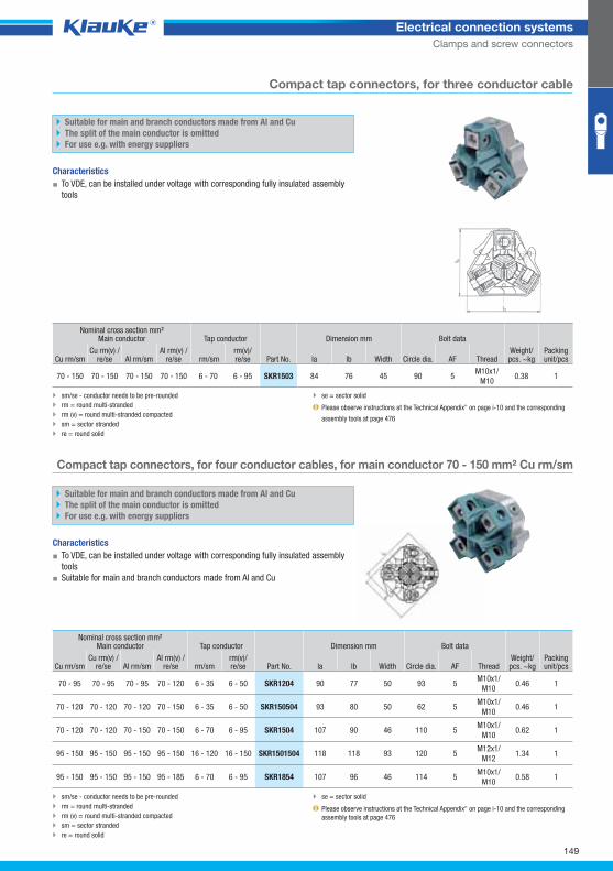
skr1204grp
149
Electrical connection systems
Clamps and screw connectors
Compact tap connectors, for four conductor cables, for main conductor 70 - 150 mm² Cu rm/sm
Suitable for main and branch conductors made from Al and Cu
The split of the main conductor is omitted
For use e.g. with energy suppliers
Characteristics
▪ To VDE, can be installed under voltage with corresponding fully insulated assembly
tools
▪ Suitable for main and branch conductors made from Al and Cu
Nominal cross section mm²Main conductor Tap conductor Dimension mm Bolt data
Weight/pcs. ~kg
Packing unit/pcs Cu rm/sm
Cu rm(v) /re/se Al rm/sm
Al rm(v) /re/se rm/sm
rm(v)/re/se Part No. la lb Width Circle dia. AF Thread
70 - 95 70 - 95 70 - 95 70 - 120 6 - 35 6 - 50 SKR1204 90 77 50 93 5 M10x1/
M10 0.46 1
70 - 120 70 - 120 70 - 120 70 - 150 6 - 35 6 - 50 SKR150504 93 80 50 62 5 M10x1/
M10 0.46 1
70 - 120 70 - 120 70 - 150 70 - 150 6 - 70 6 - 95 SKR1504 107 90 46 110 5 M10x1/
M10 0.62 1
95 - 150 95 - 150 95 - 150 95 - 150 16 - 120 16 - 150 SKR1501504 118 118 93 120 5 M12x1/
M12 1.34 1
95 - 150 95 - 150 95 - 150 95 - 185 6 - 70 6 - 95 SKR1854 107 96 46 114 5 M10x1/
M10 0.58 1
sm/se - conductor needs to be pre-rounded
rm = round multi-stranded
rm (v) = round multi-stranded compacted
sm = sector stranded
re = round solid
se = sector solid
Please observe instructions at the Technical Appendix" on page i-10 and the corresponding
assembly tools at page 476
skr1503grp Compact tap connectors, for three conductor cable
Suitable for main and branch conductors made from Al and Cu
The split of the main conductor is omitted
For use e.g. with energy suppliers
Characteristics
▪ To VDE, can be installed under voltage with corresponding fully insulated assembly
tools
Nominal cross section mm²Main conductor Tap conductor
Part No.
Dimension mm Bolt data
Weight/pcs. ~kg
Packing unit/pcs Cu rm/sm
Cu rm(v) /re/se Al rm/sm
Al rm(v) /re/se rm/sm
rm(v)/re/se la lb Width Circle dia. AF Thread
70 - 150 70 - 150 70 - 150 70 - 150 6 - 70 6 - 95 SKR1503 84 76 45 90 5 M10x1/
M10 0.38 1
sm/se - conductor needs to be pre-rounded
rm = round multi-stranded
rm (v) = round multi-stranded compacted
sm = sector stranded
re = round solid
se = sector solid
Please observe instructions at the Technical Appendix" on page i-10 and the corresponding
assembly tools at page 476
Klauke Hauptkatalog EN_DIN A5.indb 149 07.10.2014 12:17:12
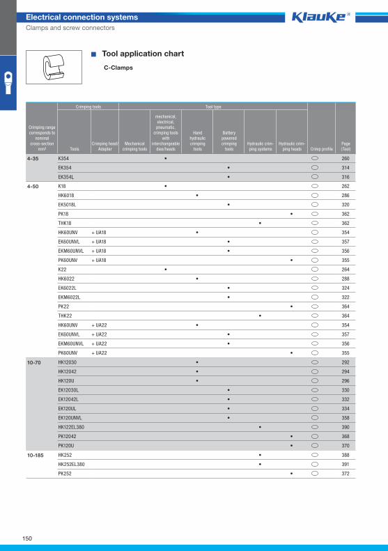
150
Electrical connection systems
Clamps and screw connectors
^WZT_Abzweig_C^ � Tool application chart
C-Clamps
Crimping tools Tool type
Crimping rangecorresponds to
nominalcross-section
mm² ToolsCrimping head/
AdapterMechanical
crimping tools
mechanical,electrical,
pneumatic, crimping tools
with interchangeable
dies/heads
Handhydraulic crimping
tools
Batterypowered crimping
toolsHydraulic crim-ping systems
Hydraulic crim-ping heads Crimp profile
Page(Tool)
K354 • 260
EK354 • 314
EK354L • 316
4-35
K18 • 262
HK6018 • 286
EK5018L • 320
PK18 • 362
THK18 • 362
HK60UNV + UA18 • 354
EK60UNVL + UA18 • 357
EKM60UNVL + UA18 • 356
PK60UNV + UA18 • 355
K22 • 264
HK6022 • 288
EK6022L • 324
EKM6022L • 322
PK22 • 364
THK22 • 364
4-50
HK60UNV + UA22 • 354
EK60UNVL + UA22 • 357
EKM60UNVL + UA22 • 356
PK60UNV + UA22 • 355
HK12030 • 292
HK12042 • 294
HK120U • 296
EK12030L • 330
EK12042L • 332
EK120UL • 334
EK120UNVL • 358
HK122EL380 • 390
PK12042 • 368
PK120U • 370
10-70
HK252 • 388
HK252EL380 • 391
PK252 • 372
10-185
Klauke Hauptkatalog EN_DIN A5.indb 150 07.10.2014 12:17:13
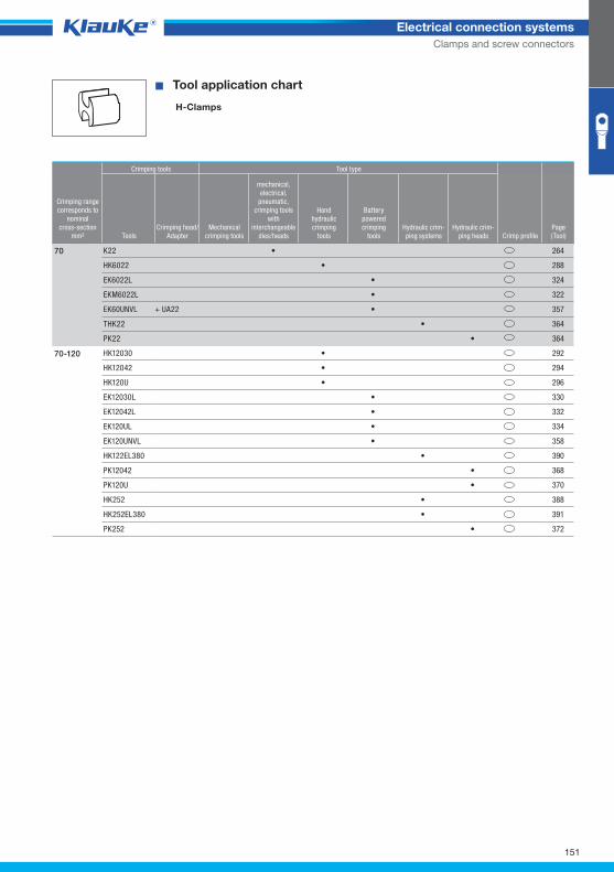
151
Electrical connection systems
Clamps and screw connectors
^WZT_Abzweig_H^ � Tool application chart
H-Clamps
Crimping tools Tool type
Crimping rangecorresponds to
nominalcross-section
mm² ToolsCrimping head/
AdapterMechanical
crimping tools
mechanical,electrical,
pneumatic, crimping tools
with interchangeable
dies/heads
Handhydraulic crimping
tools
Batterypowered crimping
toolsHydraulic crim-ping systems
Hydraulic crim-ping heads Crimp profile
Page(Tool)
K22 • 264
HK6022 • 288
EK6022L • 324
EKM6022L • 322
EK60UNVL + UA22 • 357
THK22 • 364
PK22 • 364
70
HK12030 • 292
HK12042 • 294
HK120U • 296
EK12030L • 330
EK12042L • 332
EK120UL • 334
EK120UNVL • 358
HK122EL380 • 390
PK12042 • 368
PK120U • 370
HK252 • 388
HK252EL380 • 391
PK252 • 372
70-120
Klauke Hauptkatalog EN_DIN A5.indb 151 07.10.2014 12:17:13
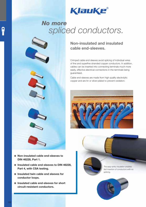
No morespliced conductors.
Crimped cable end-sleeves avoid splicing of individual wires of fi ne and superfi ne stranded copper conductors. In addition, cables can be inserted into connecting terminals much more easily, effective electrical connections in the terminals being guaranteed.
Cable end-sleeves are made from high quality electrolytic copper and are tin or silver-plated to prevent oxidation.
Non-insulated and insulated
cable end-sleeves.
◾ Non-insulated cable end-sleeves to
DIN 46228, Part 1.
◾ Insulated cable end-sleeves to DIN 46228,
Part 4, with CSA testing.
◾ Insulated twin cable end sleeves for
conductor loops.
◾ Insulated cable end-sleeves for short
circuit-resistant conductors.
The easy-entry insulation enables
fast insertion of conductors with no
splicing.
152
Klauke Hauptkatalog EN_DIN A5.indb 152 07.10.2014 12:17:13
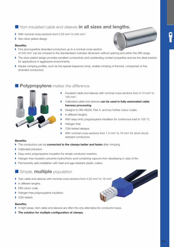
■ Polypropylene makes the difference.
▸ Insulated cable end-sleeves with nominal cross-sections from 0.14 mm2 to
150 mm2.
▸ Calibrated cable end-sleeves can be used in fully-automated cable
harness processing.
▸ Designs to DIN 46228, Part 4, and two further colour codes.
▸ In different lengths.
▸ With easy-entry polypropylene insulation for continuous load to 105 °C.
▸ Halogen-free
▸ CSA-tested designs.
▸ With nominal cross-sections from 1.5 mm2 to 16 mm2 for short circuit-
resistant conductors.
Benefi ts: ▸ The conductors can be connected to the clamps better and faster after crimping.
▸ Calibrated precision.
▸ Easy-entry polypropylene insulation for simple conductor insertion.
▸ Halogen-free insulation prevents hydrochloric acid-containing vapours from developing in case of fi re.
▸ Permanently safe installation with heat and age-resistant plastic collars.
■ Non-insulated cable end-sleeves in all sizes and lengths.
▸ With nominal cross sections from 0.25 mm2 to 240 mm2.
▸ Also silver plated design.
Benefi ts: ▸ Fine and superfi ne stranded conductors up to a nominal cross section
of 240 mm2 can be crimped to the standardized chamber dimension without splicing and within the DIN range.
▸ The silver plated design provides excellent conductivity and outstanding contact properties and are the ideal solution
for applications in aggressive environments.
▸ Klauke crimping profi les, such as the special trapezoid crimp, enable crimping of thinned, compacted or fi ne
stranded conductors.
■ Simple, multiple population.
▸ Twin cable end-sleeves with nominal cross sections from 0.25 mm2 to 16 mm2.
▸ In different lengths.
▸ DIN colour code.
▸ Halogen-free polypropylene insulation.
▸ CSA-tested.
Benefi ts: ▸ In tight areas, twin cable end-sleeves are often the only alternative for conductor loops.
▸ The solution for multiple confi guration of clamps.
153
Klauke Hauptkatalog EN_DIN A5.indb 153 07.10.2014 12:17:15
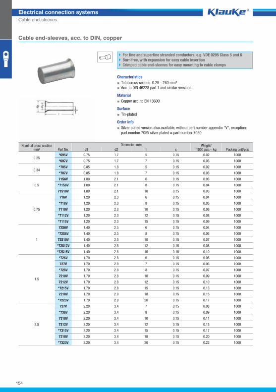
695vgrp
154
Electrical connection systems
Cable end-sleeves
Cable end-sleeves, acc. to DIN, copper
For fine and superfine stranded conductors, e.g. VDE 0295 Class 5 and 6
Burr-free, with expansion for easy cable insertion
Crimped cable end-sleeves for easy mounting to cable clamps
Characteristics
▪ Total cross-section: 0.25 - 240 mm²
▪ Acc. to DIN 46228 part 1 and similar versions
Material
▪ Copper acc. to EN 13600
Surface
▪ Tin-plated
Order info
▪ Silver plated version also available, without part number appendix "V", exception:
part number 705V silver plated = part number 7050
Nominal cross section mm² Part No.
Dimension mm Weight/1000 pcs.~ kg Packing unit/pcs d1 d2 l s
0.25 *695V 0.75 1.7 5 0.15 0.02 1000
*697V 0.75 1.7 7 0.15 0.03 1000
0.34 *705V 0.85 1.8 5 0.15 0.02 1000
*707V 0.85 1.8 7 0.15 0.03 1000
0.5
71S6V 1.00 2.1 6 0.15 0.03 1000
*71S8V 1.00 2.1 8 0.15 0.04 1000
71S10V 1.00 2.1 10 0.15 0.05 1000
0.75
716V 1.20 2.3 6 0.15 0.04 1000
*718V 1.20 2.3 8 0.15 0.05 1000
7110V 1.20 2.3 10 0.15 0.06 1000
*7112V 1.20 2.3 12 0.15 0.08 1000
*7115V 1.20 2.3 15 0.15 0.09 1000
1
72S6V 1.40 2.5 6 0.15 0.04 1000
*72S8V 1.40 2.5 8 0.15 0.06 1000
72S10V 1.40 2.5 10 0.15 0.07 1000
*72S12V 1.40 2.5 12 0.15 0.08 1000
*72S15V 1.40 2.5 15 0.15 0.10 1000
1.5
*726V 1.70 2.8 6 0.15 0.05 1000
727V 1.70 2.8 7 0.15 0.06 1000
*728V 1.70 2.8 8 0.15 0.07 1000
7210V 1.70 2.8 10 0.15 0.09 1000
7212V 1.70 2.8 12 0.15 0.10 1000
*7215V 1.70 2.8 15 0.15 0.13 1000
7218V 1.70 2.8 18 0.15 0.15 1000
*7220V 1.70 2.8 20 0.15 0.17 1000
2.5
737V 2.20 3.4 7 0.15 0.08 1000
*738V 2.20 3.4 8 0.15 0.09 1000
7310V 2.20 3.4 10 0.15 0.11 1000
7312V 2.20 3.4 12 0.15 0.13 1000
*7315V 2.20 3.4 15 0.15 0.17 1000
7318V 2.20 3.4 18 0.15 0.20 1000
*7320V 2.20 3.4 20 0.15 0.22 1000
Klauke Hauptkatalog EN_DIN A5.indb 154 07.10.2014 12:17:16
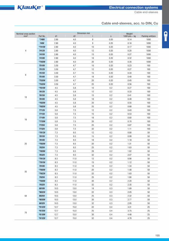
155
Electrical connection systems
Cable end-sleeves
Cable end-sleeves, acc. to DIN, Cu
Nominal cross section mm² Part No.
Dimension mm Weight/1000 pcs.~ kg Packing unit/pcs d1 d2 l s
4
*748V 2.80 4.0 8 0.20 0.14 1000
749V 2.80 4.0 9 0.20 0.16 1000
*7410V 2.80 4.0 10 0.20 0.17 1000
7412V 2.80 4.0 12 0.20 0.20 1000
7415V 2.80 4.0 15 0.20 0.27 1000
7418V 2.80 4.0 18 0.20 0.32 1000
*7420V 2.80 4.0 20 0.20 0.35 1000
6
7510V 3.50 4.7 10 0.20 0.23 100
7512V 3.50 4.7 12 0.20 0.27 100
7515V 3.50 4.7 15 0.20 0.34 100
7518V 3.50 4.7 18 0.20 0.40 100
*7520V 3.50 4.7 20 0.20 0.45 100
*7525V 3.50 4.7 25 0.20 0.56 100
10
*7610V 4.5 5.8 10 0.2 0.27 100
7612V 4.5 5.8 12 0.2 0.33 100
7615V 4.5 5.8 15 0.2 0.41 100
7618V 4.5 5.8 18 0.2 0.49 100
*7620V 4.5 5.8 20 0.2 0.55 100
*7625V 4.5 5.8 25 0.2 0.68 100
16
7712V 5.8 7.5 12 0.2 0.43 100
7715V 5.8 7.5 15 0.2 0.53 100
7718V 5.8 7.5 18 0.2 0.60 100
*7720V 5.8 7.5 20 0.2 0.70 100
7725V 5.8 7.5 25 0.2 0.87 100
7732V 5.8 7.5 32 0.2 1.11 100
25
*7812V 7.3 9.5 12 0.2 0.80 50
7815V 7.3 9.5 15 0.2 0.99 50
7818V 7.3 9.5 18 0.2 1.18 50
*7820V 7.3 9.5 20 0.2 1.31 50
7825V 7.3 9.5 25 0.2 1.63 50
*7828V 7.3 9.5 28 0.2 1.82 50
7832V 7.3 9.5 32 0.2 2.07 50
35
*7912V 8.3 11.0 12 0.2 0.90 50
*7915V 8.3 11.0 15 0.2 1.12 50
7918V 8.3 11.0 18 0.2 1.34 50
*7920V 8.3 11.0 20 0.2 1.48 50
*7922V 8.3 11.0 22 0.2 1.63 50
7925V 8.3 11.0 25 0.2 1.80 50
*7930V 8.3 11.0 30 0.2 2.20 50
7932V 8.3 11.0 32 0.2 2.35 50
50
8018V 10.5 13.0 18 0.3 1.69 50
*8022V 10.5 13.0 22 0.3 2.05 50
8025V 10.5 13.0 25 0.3 2.32 50
*8030V 10.5 13.0 30 0.3 2.77 50
8032V 10.5 13.0 32 0.3 2.95 50
70
*8122V 12.7 15.0 22 0.4 3.31 25
*8125V 12.7 15.0 25 0.4 3.75 25
*8130V 12.7 15.0 30 0.4 4.48 25
*8132V 12.7 15.0 32 0.4 4.78 25
Klauke Hauptkatalog EN_DIN A5.indb 155 07.10.2014 12:17:17
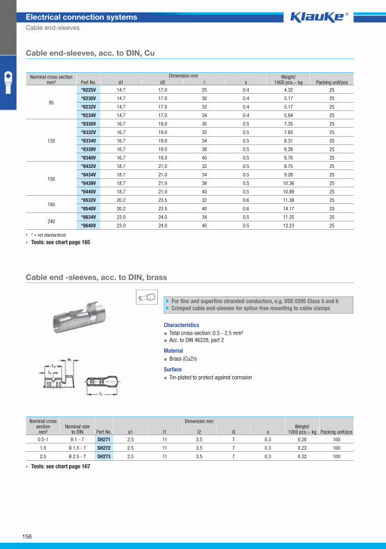
sh271grp
156
Electrical connection systems
Cable end-sleeves
Cable end-sleeves, acc. to DIN, Cu
* = not standardized
Tools: see chart page 165
Cable end -sleeves, acc. to DIN, brass
For fine and superfine stranded conductors, e.g. VDE 0295 Class 5 and 6
Crimped cable end-sleeves for splice-free mounting to cable clamps
Characteristics
▪ Total cross-section: 0.5 - 2.5 mm²
▪ Acc. to DIN 46228, part 2
Material
▪ Brass (CuZn)
Surface
▪ Tin-plated to protect against corrosion
Tools: see chart page 167
Nominal cross section mm² Part No.
Dimension mm Weight/1000 pcs.~ kg Packing unit/pcs d1 d2 l s
95
*8225V 14.7 17.0 25 0.4 4.32 25
*8230V 14.7 17.0 30 0.4 5.17 25
*8232V 14.7 17.0 32 0.4 5.17 25
*8234V 14.7 17.0 34 0.4 5.84 25
120
*8330V 16.7 19.0 30 0.5 7.35 25
*8332V 16.7 19.0 32 0.5 7.83 25
*8334V 16.7 19.0 34 0.5 8.31 25
*8338V 16.7 19.0 38 0.5 9.28 25
*8340V 16.7 19.0 40 0.5 9.76 25
150
*8432V 18.7 21.0 32 0.5 8.75 25
*8434V 18.7 21.0 34 0.5 9.28 25
*8438V 18.7 21.0 38 0.5 10.36 25
*8440V 18.7 21.0 40 0.5 10.89 25
185 *8532V 20.2 23.5 32 0.6 11.38 25
*8540V 20.2 23.5 40 0.6 14.17 25
240 *8634V 23.0 24.0 34 0.5 11.25 25
*8640V 23.0 24.0 40 0.5 13.23 25
Nominal cross section mm²
Nominal sizeto DIN Part No.
Dimension mm Weight/
1000 pcs.~ kg Packing unit/pcs a1 l1 l2 l3 s
0.5-1 B 1 - 7 SH271 2.5 11 3.5 7 0.3 0.20 100
1.5 B 1.5 - 7 SH272 2.5 11 3.5 7 0.3 0.23 100
2.5 B 2.5 - 7 SH273 2.5 11 3.5 7 0.3 0.32 100
Klauke Hauptkatalog EN_DIN A5.indb 156 07.10.2014 12:17:17
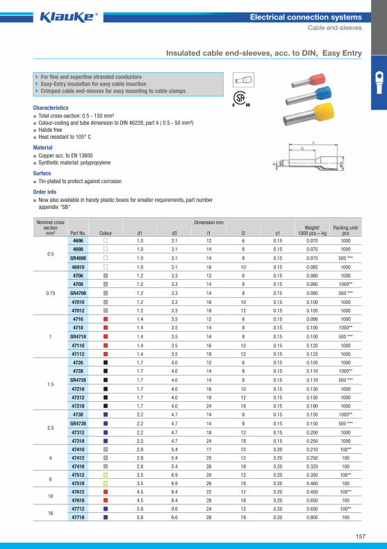
4696grp
157
Electrical connection systems
Cable end-sleeves
Insulated cable end-sleeves, acc. to DIN, Easy Entry
For fine and superfine stranded conductors
Easy-Entry insulation for easy cable insertion
Crimped cable end-sleeves for easy mounting to cable clamps
Characteristics
▪ Total cross-section: 0.5 - 150 mm²
▪ Colour-coding and tube dimension to DIN 46228, part 4 ( 0.5 - 50 mm²)
▪ Halide free
▪ Heat resistant to 105° C
Material
▪ Copper acc. to EN 13600
▪ Synthetic material: polypropylene
Surface
▪ Tin-plated to protect against corrosion
Order info
▪ Now also available in handy plastic boxes for smaller requirements, part number
appendix "SB"
Nominal cross section mm² Part No. Colour
Dimension mm Weight/
1000 pcs.~ kg Packing unit/
pcs d1 d3 l1 l2 s1
0.5
4696 1.0 3.1 12 6 0.15 0.070 1000
4698 1.0 3.1 14 8 0.15 0.070 1000
GR4698 1.0 3.1 14 8 0.15 0.070 500 ***
46910 1.0 3.1 16 10 0.15 0.085 1000
0.75
4706 1.2 3.3 12 6 0.15 0.080 1000
4708 1.2 3.3 14 8 0.15 0.080 1000**
GR4708 1.2 3.3 14 8 0.15 0.080 500 ***
47010 1.2 3.3 16 10 0.15 0.100 1000
47012 1.2 3.3 18 12 0.15 0.105 1000
1
4716 1.4 3.5 12 6 0.15 0.090 1000
4718 1.4 3.5 14 8 0.15 0.100 1000**
GR4718 1.4 3.5 14 8 0.15 0.100 500 ***
47110 1.4 3.5 16 10 0.15 0.120 1000
47112 1.4 3.5 18 12 0.15 0.125 1000
1.5
4726 1.7 4.0 12 6 0.15 0.105 1000
4728 1.7 4.0 14 8 0.15 0.110 1000**
GR4728 1.7 4.0 14 8 0.15 0.110 500 ***
47210 1.7 4.0 16 10 0.15 0.130 1000
47212 1.7 4.0 18 12 0.15 0.150 1000
47218 1.7 4.0 24 18 0.15 0.190 1000
2.5
4738 2.2 4.7 14 8 0.15 0.150 1000**
GR4738 2.2 4.7 14 8 0.15 0.150 500 ***
47312 2.2 4.7 18 12 0.15 0.200 1000
47318 2.2 4.7 24 18 0.15 0.250 1000
4
47410 2.8 5.4 17 10 0.20 0.210 100**
47412 2.8 5.4 20 12 0.20 0.250 100
47418 2.8 5.4 26 18 0.20 0.320 100
6 47512 3.5 6.9 20 12 0.20 0.350 100**
47518 3.5 6.9 26 18 0.20 0.460 100
10 47612 4.5 8.4 22 12 0.20 0.450 100**
47618 4.5 8.4 28 18 0.20 0.650 100
16 47712 5.8 9.6 24 12 0.20 0.650 100**
47718 5.8 9.6 28 18 0.20 0.800 100
Klauke Hauptkatalog EN_DIN A5.indb 157 07.10.2014 12:17:17
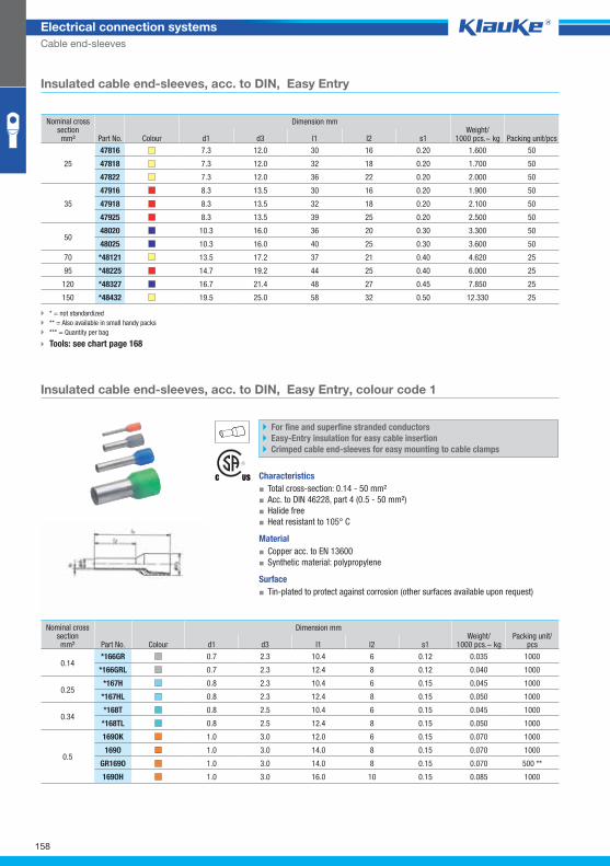
166grgrp
158
Electrical connection systems
Cable end-sleeves
Insulated cable end-sleeves, acc. to DIN, Easy Entry
* = not standardized
** = Also available in small handy packs
*** = Quantity per bag
Tools: see chart page 168
Insulated cable end-sleeves, acc. to DIN, Easy Entry, colour code 1
For fine and superfine stranded conductors
Easy-Entry insulation for easy cable insertion
Crimped cable end-sleeves for easy mounting to cable clamps
Characteristics
▪ Total cross-section: 0.14 - 50 mm²
▪ Acc. to DIN 46228, part 4 (0.5 - 50 mm²)
▪ Halide free
▪ Heat resistant to 105° C
Material
▪ Copper acc. to EN 13600
▪ Synthetic material: polypropylene
Surface
▪ Tin-plated to protect against corrosion (other surfaces available upon request)
Nominal cross section mm² Part No. Colour
Dimension mm Weight/
1000 pcs.~ kg Packing unit/pcs d1 d3 l1 l2 s1
25
47816 7.3 12.0 30 16 0.20 1.600 50
47818 7.3 12.0 32 18 0.20 1.700 50
47822 7.3 12.0 36 22 0.20 2.000 50
35
47916 8.3 13.5 30 16 0.20 1.900 50
47918 8.3 13.5 32 18 0.20 2.100 50
47925 8.3 13.5 39 25 0.20 2.500 50
50 48020 10.3 16.0 36 20 0.30 3.300 50
48025 10.3 16.0 40 25 0.30 3.600 50
70 *48121 13.5 17.2 37 21 0.40 4.620 25
95 *48225 14.7 19.2 44 25 0.40 6.000 25
120 *48327 16.7 21.4 48 27 0.45 7.850 25
150 *48432 19.5 25.0 58 32 0.50 12.330 25
Nominal cross section mm² Part No. Colour
Dimension mm Weight/
1000 pcs.~ kg Packing unit/
pcs d1 d3 l1 l2 s1
0.14 *166GR 0.7 2.3 10.4 6 0.12 0.035 1000
*166GRL 0.7 2.3 12.4 8 0.12 0.040 1000
0.25 *167H 0.8 2.3 10.4 6 0.15 0.045 1000
*167HL 0.8 2.3 12.4 8 0.15 0.050 1000
0.34 *168T 0.8 2.5 10.4 6 0.15 0.045 1000
*168TL 0.8 2.5 12.4 8 0.15 0.050 1000
0.5
169OK 1.0 3.0 12.0 6 0.15 0.070 1000
169O 1.0 3.0 14.0 8 0.15 0.070 1000
GR169O 1.0 3.0 14.0 8 0.15 0.070 500 **
169OH 1.0 3.0 16.0 10 0.15 0.085 1000
Klauke Hauptkatalog EN_DIN A5.indb 158 07.10.2014 12:17:18
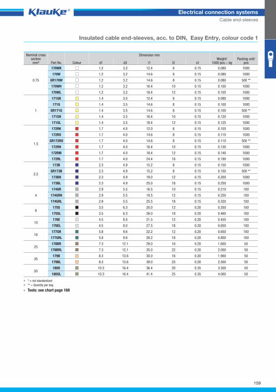
159
Electrical connection systems
Cable end-sleeves
Insulated cable end-sleeves, acc. to DIN, Easy Entry, colour code 1
* = not standardized
** = Quantity per bag
Tools: see chart page 168
Nominal cross section mm² Part No. Colour
Dimension mm Weight/
1000 pcs.~ kg Packing unit/
pcs d1 d3 l1 l2 s1
0.75
170WK 1.2 3.2 12.4 6 0.15 0.080 1000
170W 1.2 3.2 14.6 8 0.15 0.080 1000
GR170W 1.2 3.2 14.6 8 0.15 0.080 500 **
170WH 1.2 3.2 16.4 10 0.15 0.100 1000
170WL 1.2 3.2 18.4 12 0.15 0.105 1000
1
171GK 1.4 3.5 12.4 6 0.15 0.090 1000
171G 1.4 3.5 14.6 8 0.15 0.100 1000
GR171G 1.4 3.5 14.6 8 0.15 0.100 500 **
171GH 1.4 3.5 16.4 10 0.15 0.120 1000
171GL 1.4 3.5 18.4 12 0.15 0.125 1000
1.5
172RK 1.7 4.0 12.0 6 0.15 0.105 1000
172RO 1.7 4.0 14.6 8 0.15 0.110 1000
GR172RO 1.7 4.0 14.6 8 0.15 0.110 500 **
172RH 1.7 4.0 16.4 10 0.15 0.130 1000
172RM 1.7 4.0 18.4 12 0.15 0.140 1000
172RL 1.7 4.0 24.4 18 0.15 0.190 1000
2.5
173B 2.3 4.9 15.2 8 0.15 0.150 1000
GR173B 2.3 4.9 15.2 8 0.15 0.150 500 **
173BH 2.3 4.9 19.0 12 0.15 0.200 1000
173BL 2.3 4.9 25.0 18 0.15 0.250 1000
4
174GR 2.9 5.5 16.5 10 0.15 0.210 100
174GRH 2.9 5.5 19.5 12 0.15 0.250 100
174GRL 2.9 5.5 25.5 18 0.15 0.320 100
6 175S 3.5 6.3 20.0 12 0.20 0.350 100
175SL 3.5 6.3 26.0 18 0.20 0.460 100
10 176E 4.5 8.0 21.5 12 0.20 0.450 100
176EL 4.5 8.0 27.5 18 0.20 0.650 100
16 177GR 5.8 9.6 22.2 12 0.20 0.650 100
177GRL 5.8 9.6 28.2 18 0.20 0.800 100
25 178BR 7.3 12.1 29.0 16 0.20 1.600 50
178BRL 7.3 12.1 35.0 22 0.20 2.000 50
35 179B 8.3 13.6 30.0 16 0.20 1.900 50
179BL 8.3 13.6 39.0 25 0.20 2.500 50
50 180O 10.3 16.4 36.4 20 0.35 3.300 50
180OL 10.3 16.4 41.4 25 0.35 4.000 50
Klauke Hauptkatalog EN_DIN A5.indb 159 07.10.2014 12:17:19
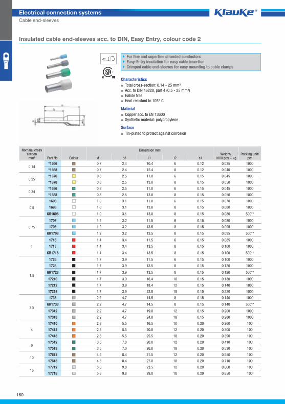
1666grp
160
Electrical connection systems
Cable end-sleeves
Insulated cable end-sleeves acc. to DIN, Easy Entry, colour code 2
For fine and superfine stranded conductors
Easy-Entry insulation for easy cable insertion
Crimped cable end-sleeves for easy mounting to cable clamps
Characteristics
▪ Total cross-section: 0.14 - 25 mm²
▪ Acc. to DIN 46228, part 4 (0.5 - 25 mm²)
▪ Halide free
▪ Heat resistant to 105° C
Material
▪ Copper acc. to EN 13600
▪ Synthetic material: polypropylene
Surface
▪ Tin-plated to protect against corrosion
Nominal cross section mm² Part No. Colour
Dimension mm Weight/
1000 pcs.~ kg Packing unit/
pcs d1 d3 l1 l2 s1
0.14 *1666 0.7 2.4 10.4 6 0.12 0.035 1000
*1668 0.7 2.4 12.4 8 0.12 0.040 1000
0.25 *1676 0.8 2.5 11.0 6 0.15 0.045 1000
*1678 0.8 2.5 13.0 8 0.15 0.050 1000
0.34 *1686 0.8 2.5 11.0 6 0.15 0.045 1000
*1688 0.8 2.5 13.0 8 0.15 0.050 1000
0.5
1696 1.0 3.1 11.0 6 0.15 0.070 1000
1698 1.0 3.1 13.0 8 0.15 0.080 1000
GR1698 1.0 3.1 13.0 8 0.15 0.080 500**
0.75
1706 1.2 3.2 11.5 6 0.15 0.080 1000
1708 1.2 3.2 13.5 8 0.15 0.095 1000
GR1708 1.2 3.2 13.5 8 0.15 0.095 500**
1
1716 1.4 3.4 11.5 6 0.15 0.085 1000
1718 1.4 3.4 13.5 8 0.15 0.100 1000
GR1718 1.4 3.4 13.5 8 0.15 0.100 500**
1.5
1726 1.7 3.9 11.5 6 0.15 0.100 1000
1728 1.7 3.9 13.5 8 0.15 0.120 1000
GR1728 1.7 3.9 13.5 8 0.15 0.120 500**
17210 1.7 3.9 16.4 10 0.15 0.130 1000
17212 1.7 3.9 18.4 12 0.15 0.140 1000
17218 1.7 3.9 22.8 18 0.15 0.220 1000
2.5
1738 2.2 4.7 14.5 8 0.15 0.140 1000
GR1738 2.2 4.7 14.5 8 0.15 0.140 500**
17312 2.2 4.7 19.0 12 0.15 0.200 1000
17318 2.2 4.7 24.0 18 0.15 0.280 1000
4
17410 2.8 5.5 16.5 10 0.20 0.260 100
17412 2.8 5.5 20.0 12 0.20 0.300 100
17418 2.8 5.5 25.5 18 0.20 0.390 100
6 17512 3.5 7.0 20.0 12 0.20 0.410 100
17518 3.5 7.0 26.0 18 0.20 0.530 100
10 17612 4.5 8.4 21.5 12 0.20 0.550 100
17618 4.5 8.4 27.0 18 0.20 0.710 100
16 17712 5.8 9.8 23.5 12 0.20 0.660 100
17718 5.8 9.8 29.0 18 0.20 0.850 100
Klauke Hauptkatalog EN_DIN A5.indb 160 07.10.2014 12:17:19
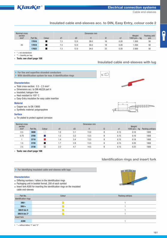
3698grp
3800_GRP01
161
Electrical connection systems
Cable end-sleeves
Insulated cable end-sleeves acc. to DIN, Easy Entry, colour code 2
* = not standardized
** = Quantity per bag
Tools: see chart page 168
Insulated cable end-sleeves with lug
For fine and superfine stranded conductors
With identification system for max. 6 identification rings
Characteristics
▪ Total cross-section: 0.5 - 2.5 mm²
▪ Dimensions acc. to DIN 46228 part 4
▪ Insulated, halogen-free
▪ Heat resistant to 105° C
▪ Easy-Entry insulation for easy cable insertion
Material
▪ Copper acc. to EN 13600
▪ Synthetic material: polypropylene
Surface
▪ Tin-plated to protect against corrosion
Tools: see chart page 168
Identification rings and insert fork
For identifying insulated cable end-sleeves with lugs
Characteristics
▪ Differing numbers / letters in the identification rings
▪ Packaging unit in booklet format, 200 of each symbol
▪ Insert fork A300 for inserting the identification rings on the insulated
cable end-sleeves
* = without letters "I" and "O"
Nominal cross section mm² Part No. Colour
Dimension mm Weight/
1000 pcs.~ kg Packing unit/
pcs d1 d3 l1 l2 s1
25
17816 7.3 12.0 28.0 16 0.20 1.500 50
17818 7.3 12.0 30.0 18 0.20 1.550 50
17822 7.3 12.0 34.0 22 0.20 2.000 50
Nominal cross section mm² Part No. Colour
Dimension mm Weight/
1000 pcs.~ kg Packing unit/pcs d1 d3 l1 l2 s1
0.5 3698 1.0 3.1 13.0 8 0.15 0.16 1000
0.75 3708 1.2 3.2 13.5 8 0.15 0.16 1000
1 3718 1.4 3.4 13.5 8 0.15 0.18 1000
1.5 3728 1.7 3.9 13.5 8 0.15 0.20 1000
2.5 3738 2.2 4.7 14.5 8 0.15 0.22 1000
Part No. Colour Packing unit/pcs
Identification rings
380/- 1
380/+ 1
380/0 bis 9 1
380/A bis Z* 1
Insert fork
A300 1
Klauke Hauptkatalog EN_DIN A5.indb 161 07.10.2014 12:17:20
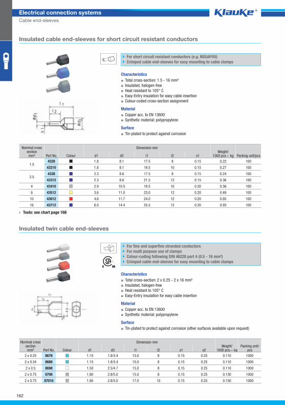
4328grp
8678grp
162
Electrical connection systems
Cable end-sleeves
Insulated cable end-sleeves for short circuit resistant conductors
For short circuit resistant conductors (e.g. NSGAFOU)
Crimped cable end-sleeves for easy mounting to cable clamps
Characteristics
▪ Total cross-section: 1.5 - 16 mm²
▪ Insulated, halogen-free
▪ Heat resistant to 105° C
▪ Easy-Entry insulation for easy cable insertion
▪ Colour-coded cross-section assignment
Material
▪ Copper acc. to EN 13600
▪ Synthetic material: polypropylene
Surface
▪ Tin-plated to protect against corrosion
Tools: see chart page 168
Insulated twin cable end-sleeves
For fine and superfine stranded conductors
For multi purpose use of clamps
Colour-coding following DIN 46228 part 4 (0.5 - 16 mm²)
Crimped cable end-sleeves for easy mounting to cable clamps
Characteristics
▪ Total cross-section: 2 x 0.25 - 2 x 16 mm²
▪ Insulated, halogen-free
▪ Heat resistant to 105° C
▪ Easy-Entry insulation for easy cable insertion
Material
▪ Copper acc. to EN 13600
▪ Synthetic material: polypropylene
Surface
▪ Tin-plated to protect against corrosion (other surfaces available upon request)
Nominal cross section mm² Part No. Colour
Dimension mm Weight/
1000 pcs.~ kg Packing unit/pcs d1 d3 l1 l2 s1
1.5 4328 1.8 8.1 17.5 8 0.15 0.22 100
43210 1.8 8.1 19.5 10 0.15 0.27 100
2.5 4338 2.3 8.6 17.5 8 0.15 0.24 100
43312 2.3 8.6 21.5 12 0.15 0.36 100
4 43410 2.9 10.5 19.5 10 0.20 0.36 100
6 43512 3.6 11.0 23.0 12 0.20 0.49 100
10 43612 4.6 11.7 24.0 12 0.20 0.65 100
16 43712 6.0 14.4 25.5 12 0.20 0.93 100
Nominal cross section mm² Part No. Colour
Dimension mm Weight/
1000 pcs.~ kg Packing unit/
pcs d1 d3 l1 l2 s1 s2
2 x 0.25 8678 1.15 1.8/3.4 15.0 8 0.15 0.25 0.110 1000
2 x 0.34 8688 1.15 1.8/3.4 15.0 8 0.15 0.25 0.110 1000
2 x 0.5 8698 1.50 2.5/4.7 15.0 8 0.15 0.25 0.110 1000
2 x 0.75 8708 1.80 2.8/5.0 15.0 8 0.15 0.25 0.130 1000
2 x 0.75 87010 1.80 2.8/5.0 17.0 10 0.15 0.25 0.150 1000
Klauke Hauptkatalog EN_DIN A5.indb 162 07.10.2014 12:17:20
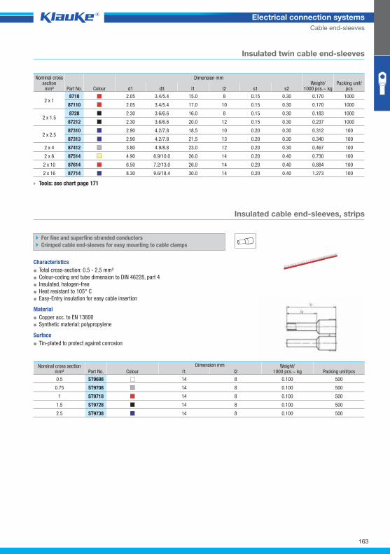
st9698grp
163
Electrical connection systems
Cable end-sleeves
Insulated twin cable end-sleeves
Tools: see chart page 171
Insulated cable end-sleeves, strips
For fine and superfine stranded conductors
Crimped cable end-sleeves for easy mounting to cable clamps
Characteristics
▪ Total cross-section: 0.5 - 2.5 mm²
▪ Colour-coding and tube dimension to DIN 46228, part 4
▪ Insulated, halogen-free
▪ Heat resistant to 105° C
▪ Easy-Entry insulation for easy cable insertion
Material
▪ Copper acc. to EN 13600
▪ Synthetic material: polypropylene
Surface
▪ Tin-plated to protect against corrosion
Nominal cross section mm² Part No. Colour
Dimension mm Weight/
1000 pcs.~ kg Packing unit/
pcs d1 d3 l1 l2 s1 s2
2 x 1 8718 2.05 3.4/5.4 15.0 8 0.15 0.30 0.170 1000
87110 2.05 3.4/5.4 17.0 10 0.15 0.30 0.170 1000
2 x 1.5 8728 2.30 3.6/6.6 16.0 8 0.15 0.30 0.183 1000
87212 2.30 3.6/6.6 20.0 12 0.15 0.30 0.237 1000
2 x 2.5 87310 2.90 4.2/7.8 18.5 10 0.20 0.30 0.312 100
87313 2.90 4.2/7.8 21.5 13 0.20 0.30 0.340 100
2 x 4 87412 3.80 4.9/8.8 23.0 12 0.20 0.30 0.467 100
2 x 6 87514 4.90 6.9/10.0 26.0 14 0.20 0.40 0.730 100
2 x 10 87614 6.50 7.2/13.0 26.0 14 0.20 0.40 0.884 100
2 x 16 87714 8.30 9.6/18.4 30.0 14 0.20 0.40 1.273 100
Nominal cross section mm² Part No. Colour
Dimension mm Weight/1000 pcs.~ kg Packing unit/pcs l1 l2
0.5 ST9698 14 8 0.100 500
0.75 ST9708 14 8 0.100 500
1 ST9718 14 8 0.100 500
1.5 ST9728 14 8 0.100 500
2.5 ST9738 14 8 0.100 500
Klauke Hauptkatalog EN_DIN A5.indb 163 07.10.2014 12:17:21
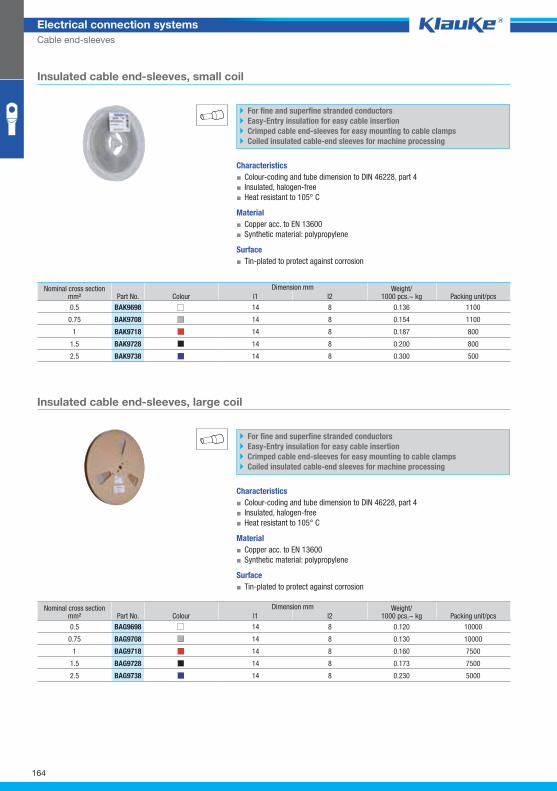
bak9698grp
bag9698grp
164
Electrical connection systems
Cable end-sleeves
Insulated cable end-sleeves, small coil
For fine and superfine stranded conductors
Easy-Entry insulation for easy cable insertion
Crimped cable end-sleeves for easy mounting to cable clamps
Coiled insulated cable-end sleeves for machine processing
Characteristics
▪ Colour-coding and tube dimension to DIN 46228, part 4
▪ Insulated, halogen-free
▪ Heat resistant to 105° C
Material
▪ Copper acc. to EN 13600
▪ Synthetic material: polypropylene
Surface
▪ Tin-plated to protect against corrosion
Insulated cable end-sleeves, large coil
For fine and superfine stranded conductors
Easy-Entry insulation for easy cable insertion
Crimped cable end-sleeves for easy mounting to cable clamps
Coiled insulated cable-end sleeves for machine processing
Characteristics
▪ Colour-coding and tube dimension to DIN 46228, part 4
▪ Insulated, halogen-free
▪ Heat resistant to 105° C
Material
▪ Copper acc. to EN 13600
▪ Synthetic material: polypropylene
Surface
▪ Tin-plated to protect against corrosion
Nominal cross section mm² Part No. Colour
Dimension mm Weight/1000 pcs.~ kg Packing unit/pcs l1 l2
0.5 BAK9698 14 8 0.136 1100
0.75 BAK9708 14 8 0.154 1100
1 BAK9718 14 8 0.187 800
1.5 BAK9728 14 8 0.200 800
2.5 BAK9738 14 8 0.300 500
Nominal cross section mm² Part No. Colour
Dimension mm Weight/1000 pcs.~ kg Packing unit/pcs l1 l2
0.5 BAG9698 14 8 0.120 10000
0.75 BAG9708 14 8 0.130 10000
1 BAG9718 14 8 0.160 7500
1.5 BAG9728 14 8 0.173 7500
2.5 BAG9738 14 8 0.230 5000
Klauke Hauptkatalog EN_DIN A5.indb 164 07.10.2014 12:17:21
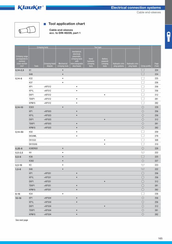
^WZT_AE_DIN46228_1^
165
Electrical connection systems
Cable end-sleeves
� Tool application chart
Cable end-sleevesacc. to DIN 46228, part 1
Crimping tools Tool type
Crimping rangecorresponds to
nominalcross-section
mm² ToolsCrimping head/
AdapterMechanical
crimping tools
mechanical,electrical,
pneumatic, crimping tools
with interchangeable
dies/heads
Handhydraulic crimping
tools
Batterypowered crimping
toolsHydraulic crim-ping systems
Hydraulic crim-ping heads Crimp profile
Page(Tool)
K1 • 224
K48 • 224
0,14-2,5
K32 • 225
K37 • 226
KP1 +KP312 • 256
KP1L +KP312 • 256
EKP1 +KP312 • 312
TEKP1 +KP312 • 281
KPM15 +KP312 • 282
0,14-6
K303 • 229
KP1 +KP303 • 256
KP1L +KP303 • 256
EKP1 +KP303 • 312
TEKP1 +KP303 • 281
KPM15 +KP303 • 282
0,14-10
K50 • 259
EK50ML • 278
EK1550 • 308
EK1550G • 310
0,14-50
K38ERGO • 2280,25-6
K4 • 2220,5-2,5
K36 • 225
K382 • 227
0,5-6
K3 • 2230,5-16
K46 • 222
KP1 +KP351 • 256
KP1L +KP351 • 256
EKP1 +KP351 • 312
TEKP1 +KP351 • 281
KPM15 +KP351 • 282
1,5-6
K34 • 2266-16
KP1 +KP304 • 256
KP1L +KP304 • 256
EKP1 +KP304 • 312
TEKP1 +KP304 • 281
KPM15 +KP304 • 282
10-16
See next page
Klauke Hauptkatalog EN_DIN A5.indb 165 07.10.2014 12:17:21
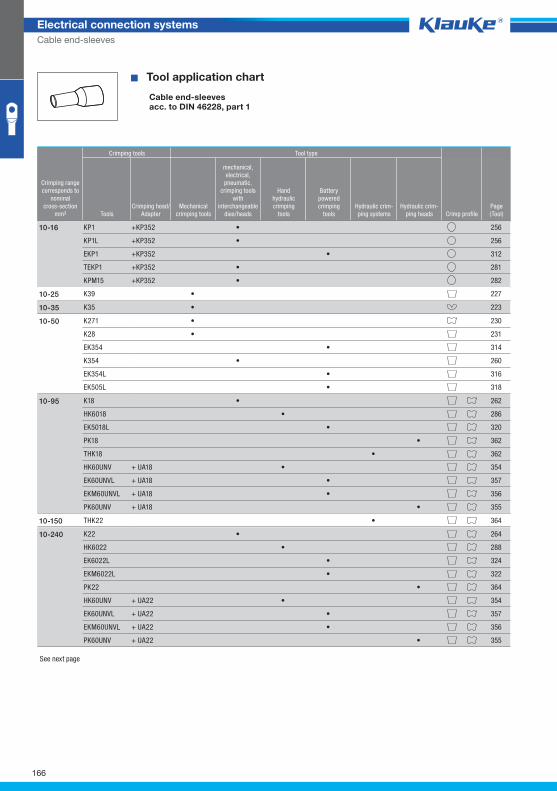
166
Electrical connection systems
Cable end-sleeves
� Tool application chart
Cable end-sleevesacc. to DIN 46228, part 1
Crimping tools Tool type
Crimping rangecorresponds to
nominalcross-section
mm² ToolsCrimping head/
AdapterMechanical
crimping tools
mechanical,electrical,
pneumatic, crimping tools
with interchangeable
dies/heads
Handhydraulic crimping
tools
Batterypowered crimping
toolsHydraulic crim-ping systems
Hydraulic crim-ping heads Crimp profile
Page(Tool)
KP1 +KP352 • 256
KP1L +KP352 • 256
EKP1 +KP352 • 312
TEKP1 +KP352 • 281
KPM15 +KP352 • 282
10-16
K39 • 22710-25
K35 • 22310-35
K271 • 230
K28 • 231
EK354 • 314
K354 • 260
EK354L • 316
EK505L • 318
10-50
K18 • 262
HK6018 • 286
EK5018L • 320
PK18 • 362
THK18 • 362
HK60UNV + UA18 • 354
EK60UNVL + UA18 • 357
EKM60UNVL + UA18 • 356
PK60UNV + UA18 • 355
10-95
THK22 • 36410-150
K22 • 264
HK6022 • 288
EK6022L • 324
EKM6022L • 322
PK22 • 364
HK60UNV + UA22 • 354
EK60UNVL + UA22 • 357
EKM60UNVL + UA22 • 356
PK60UNV + UA22 • 355
10-240
See next page
Klauke Hauptkatalog EN_DIN A5.indb 166 07.10.2014 12:17:22
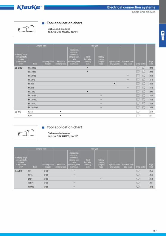
^WZT_AE_DIN46228_2^
167
Electrical connection systems
Cable end-sleeves
� Tool application chart
Cable end-sleevesacc. to DIN 46228, part 1
Crimping tools Tool type
Crimping rangecorresponds to
nominalcross-section
mm² ToolsCrimping head/
AdapterMechanical
crimping tools
mechanical,electrical,
pneumatic, crimping tools
with interchangeable
dies/heads
Handhydraulic crimping
tools
Batterypowered crimping
toolsHydraulic crim-ping systems
Hydraulic crim-ping heads Crimp profile
Page(Tool)
HK12030 • 292
HK12042 • 294
PK12042 • 368
PK120U • 370
HK252 • 388
PK252 • 372
HK120U • 296
EK12030L • 330
EK12042L • 332
EK120UL • 334
EK120UNVL • 358
25-240
K272 • 230
K29 • 231
50-95
� Tool application chart
Cable end-sleevesacc. to DIN 46228, part 2
Crimping tools Tool type
Crimping rangecorresponds to
nominalcross-section
mm² ToolsCrimping head/
AdapterMechanical
crimping tools
mechanical,electrical,
pneumatic, crimping tools
with interchangeable
dies/heads
Handhydraulic crimping
tools
Batterypowered crimping
toolsHydraulic crim-ping systems
Hydraulic crim-ping heads Crimp profile
Page(Tool)
KP1 +KP66 • 256
KP1L +KP66 • 256
EKP1 +KP66 • 312
TEKP1 +KP66 • 281
KPM15 +KP66 • 282
0.5x2.5
Klauke Hauptkatalog EN_DIN A5.indb 167 07.10.2014 12:17:22
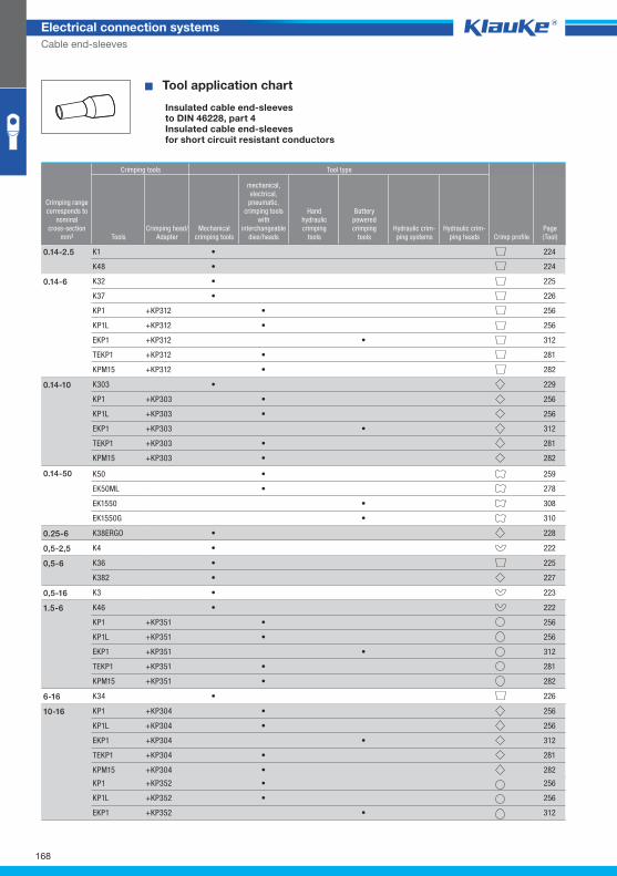
^WZT_AE_DIN46228_4^
168
Electrical connection systems
Cable end-sleeves
� Tool application chart
Insulated cable end-sleevesto DIN 46228, part 4Insulated cable end-sleevesfor short circuit resistant conductors
Crimping tools Tool type
Crimping rangecorresponds to
nominalcross-section
mm² ToolsCrimping head/
AdapterMechanical
crimping tools
mechanical,electrical,
pneumatic, crimping tools
with interchangeable
dies/heads
Handhydraulic crimping
tools
Batterypowered crimping
toolsHydraulic crim-ping systems
Hydraulic crim-ping heads Crimp profile
Page(Tool)
K1 • 224
K48 • 224
0.14-2.5
K32 • 225
K37 • 226
KP1 +KP312 • 256
KP1L +KP312 • 256
EKP1 +KP312 • 312
TEKP1 +KP312 • 281
KPM15 +KP312 • 282
0.14-6
K303 • 229
KP1 +KP303 • 256
KP1L +KP303 • 256
EKP1 +KP303 • 312
TEKP1 +KP303 • 281
KPM15 +KP303 • 282
0.14-10
K50 • 259
EK50ML • 278
EK1550 • 308
EK1550G • 310
0.14-50
K38ERGO • 2280.25-6
K4 • 2220,5-2,5
K36 • 225
K382 • 227
0,5-6
K3 • 2230,5-16
K46 • 222
KP1 +KP351 • 256
KP1L +KP351 • 256
EKP1 +KP351 • 312
TEKP1 +KP351 • 281
KPM15 +KP351 • 282
1.5-6
K34 • 2266-16
KP1 +KP304 • 256
KP1L +KP304 • 256
EKP1 +KP304 • 312
TEKP1 +KP304 • 281
KPM15 +KP304 • 282
10-16
KP1 +KP352 • 256
KP1L +KP352 • 256
EKP1 +KP352 • 312
Klauke Hauptkatalog EN_DIN A5.indb 168 07.10.2014 12:17:22
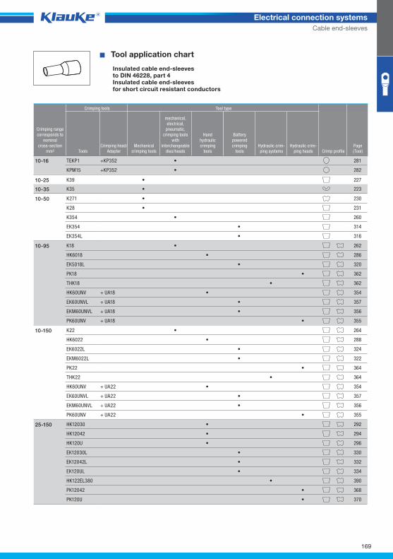
169
Electrical connection systems
Cable end-sleeves
� Tool application chart
Insulated cable end-sleevesto DIN 46228, part 4Insulated cable end-sleevesfor short circuit resistant conductors
Crimping tools Tool type
Crimping rangecorresponds to
nominalcross-section
mm² ToolsCrimping head/
AdapterMechanical
crimping tools
mechanical,electrical,
pneumatic, crimping tools
with interchangeable
dies/heads
Handhydraulic crimping
tools
Batterypowered crimping
toolsHydraulic crim-ping systems
Hydraulic crim-ping heads Crimp profile
Page(Tool)
TEKP1 +KP352 • 281
KPM15 +KP352 • 282
10-16
K39 • 22710-25
K35 • 22310-35
K271 • 230
K28 • 231
K354 • 260
EK354 • 314
EK354L • 316
10-50
K18 • 262
HK6018 • 286
EK5018L • 320
PK18 • 362
THK18 • 362
HK60UNV + UA18 • 354
EK60UNVL + UA18 • 357
EKM60UNVL + UA18 • 356
PK60UNV + UA18 • 355
10-95
K22 • 264
HK6022 • 288
EK6022L • 324
EKM6022L • 322
PK22 • 364
THK22 • 364
HK60UNV + UA22 • 354
EK60UNVL + UA22 • 357
EKM60UNVL + UA22 • 356
PK60UNV + UA22 • 355
10-150
HK12030 • 292
HK12042 • 294
HK120U • 296
EK12030L • 330
EK12042L • 332
EK120UL • 334
HK122EL380 • 390
PK12042 • 368
PK120U • 370
25-150
Klauke Hauptkatalog EN_DIN A5.indb 169 07.10.2014 12:17:23
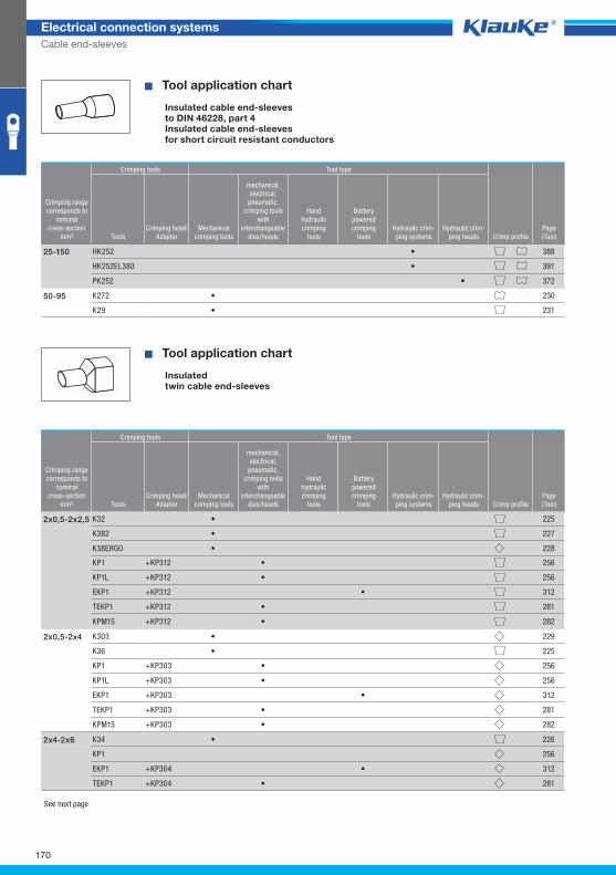
170
Electrical connection systems
Cable end-sleeves
KP1 256
EKP1 +KP304 • 312
TEKP1 +KP304 • 281
K34 • 2262x4-2x6
KP1 +KP303 • 256
KP1L +KP303 • 256
EKP1 +KP303 • 312
TEKP1 +KP303 • 281
KPM15 +KP303 • 282
KP1 +KP312 • 256
KP1L +KP312 • 256
EKP1 +KP312 • 312
TEKP1 +KP312 • 281
KPM15 +KP312 • 282
� Tool application chart
Insulated cable end-sleevesto DIN 46228, part 4Insulated cable end-sleevesfor short circuit resistant conductors
Crimping tools Tool type
Crimping rangecorresponds to
nominalcross-section
mm² ToolsCrimping head/
AdapterMechanical
crimping tools
mechanical,electrical,
pneumatic, crimping tools
with interchangeable
dies/heads
Handhydraulic crimping
tools
Batterypowered crimping
toolsHydraulic crim-ping systems
Hydraulic crim-ping heads Crimp profile
Page(Tool)
HK252 • 388
HK252EL380 • 391
PK252 • 372
25-150
K272 • 230
K29 • 231
50-95
� Tool application chart
Insulatedtwin cable end-sleeves
Crimping tools Tool type
Crimping rangecorresponds to
nominalcross-section
mm² ToolsCrimping head/
AdapterMechanical
crimping tools
mechanical,electrical,
pneumatic, crimping tools
with interchangeable
dies/heads
Handhydraulic crimping
tools
Batterypowered crimping
toolsHydraulic crim-ping systems
Hydraulic crim-ping heads Crimp profile
Page(Tool)
K32 • 225
K382 • 227
K38ERGO • 228
2x0,5-2x2,5
K303 • 229
K36 • 225
2x0,5-2x4
See next page
Klauke Hauptkatalog EN_DIN A5.indb 170 07.10.2014 12:17:23
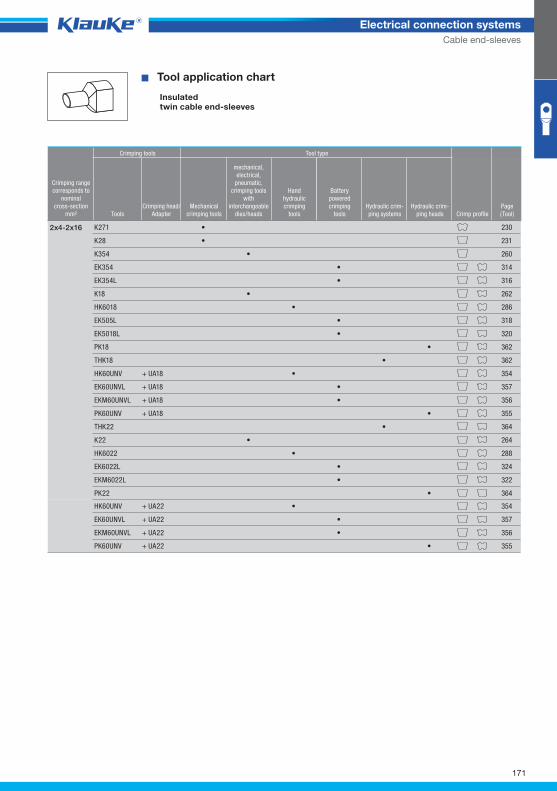
^WZT_ZAE_isoliert^
171
Electrical connection systems
Cable end-sleeves
HK60UNV + UA22 • 354
EK60UNVL + UA22 • 357
EKM60UNVL + UA22 • 356
PK60UNV + UA22 • 355
� Tool application chart
Insulatedtwin cable end-sleeves
Crimping tools Tool type
Crimping rangecorresponds to
nominalcross-section
mm² ToolsCrimping head/
AdapterMechanical
crimping tools
mechanical,electrical,
pneumatic, crimping tools
with interchangeable
dies/heads
Handhydraulic crimping
tools
Batterypowered crimping
toolsHydraulic crim-ping systems
Hydraulic crim-ping heads Crimp profile
Page(Tool)
K271 • 230
K28 • 231
K354 • 260
EK354 • 314
EK354L • 316
K18 • 262
HK6018 • 286
EK505L • 318
EK5018L • 320
PK18 • 362
THK18 • 362
HK60UNV + UA18 • 354
EK60UNVL + UA18 • 357
EKM60UNVL + UA18 • 356
PK60UNV + UA18 • 355
THK22 • 364
K22 • 264
HK6022 • 288
EK6022L • 324
EKM6022L • 322
PK22 • 364
2x4-2x16
Klauke Hauptkatalog EN_DIN A5.indb 171 07.10.2014 12:17:23
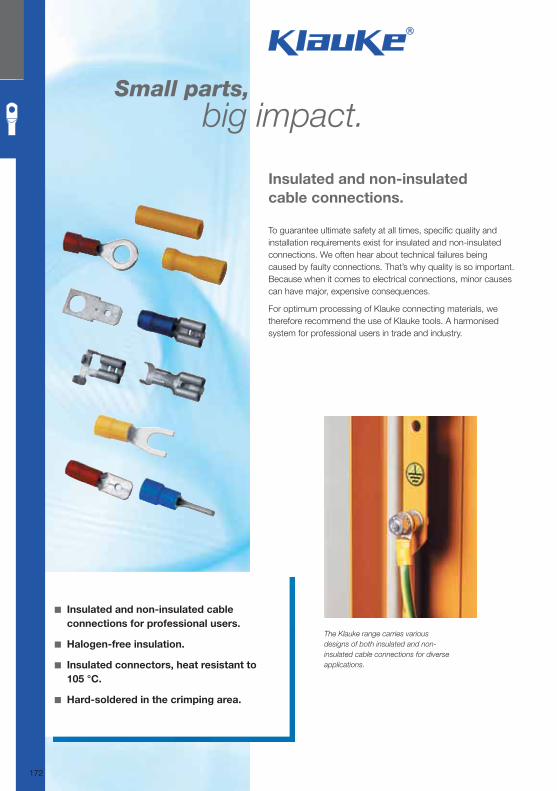
Small parts, big impact.
To guarantee ultimate safety at all times, specifi c quality and installation requirements exist for insulated and non-insulated connections. We often hear about technical failures being caused by faulty connections. That’s why quality is so important. Because when it comes to electrical connections, minor causes can have major, expensive consequences.
For optimum processing of Klauke connecting materials, we therefore recommend the use of Klauke tools. A harmonised system for professional users in trade and industry.
Insulated and non-insulated
cable connections.
◾ Insulated and non-insulated cable
connections for professional users.
◾ Halogen-free insulation.
◾ Insulated connectors, heat resistant to
105 °C.
◾ Hard-soldered in the crimping area.
The Klauke range carries various
designs of both insulated and non-
insulated cable connections for diverse
applications.
172
Klauke Hauptkatalog EN_DIN A5.indb 172 07.10.2014 12:17:24
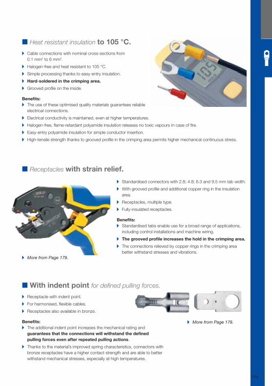
■ Heat resistant insulation to 105 °C.
▸ Cable connections with nominal cross-sections from
0.1 mm2 to 6 mm2.
▸ Halogen-free and heat resistant to 105 °C.
▸ Simple processing thanks to easy-entry insulation.
▸ Hard-soldered in the crimping area.
▸ Grooved profi le on the inside.
Benefi ts: ▸ The use of these optimised quality materials guarantees reliable
electrical connections.
▸ Electrical conductivity is maintained, even at higher temperatures.
▸ Halogen-free, fl ame-retardant polyamide insulation releases no toxic vapours in case of fi re.
▸ Easy-entry polyamide insulation for simple conductor insertion.
▸ High-tensile strength thanks to grooved profi le in the crimping area permits higher mechanical continuous stress.
▸ Standardised connectors with 2.8; 4.8; 6.3 and 9.5 mm tab width.
▸ With grooved profi le and additional copper ring in the insulation
area.
▸ Receptacles, multiple type.
▸ Fully-insulated receptacles.
Benefi ts: ▸ Standardised tabs enable use for a broad range of applications,
including control installations and machine wiring.
▸ The grooved profi le increases the hold in the crimping area.
▸ The connections relieved by copper rings in the crimping area
better withstand stresses and vibrations.
▸ More from Page 179.
■ With indent point for defi ned pulling forces.
▸ Receptacle with indent point.
▸ For harmonised, fl exible cables.
▸ Receptacles also available in bronze.
Benefi ts: ▸ The additional indent point increases the mechanical rating and
guarantees that the connections will withstand the defi ned
pulling forces even after repeated pulling actions.
▸ Thanks to the material’s improved spring characteristics, connectors with
bronze receptacles have a higher contact strength and are able to better
withstand mechanical stresses, especially at high temperatures.
▸ More from Page 179.
■ Receptacles with strain relief.
173
Klauke_Hauptkatalog_ElektrVerbindungstechnik_10_Kabelverbindungen_GB.indd 173 10.10.2014 11:38:29
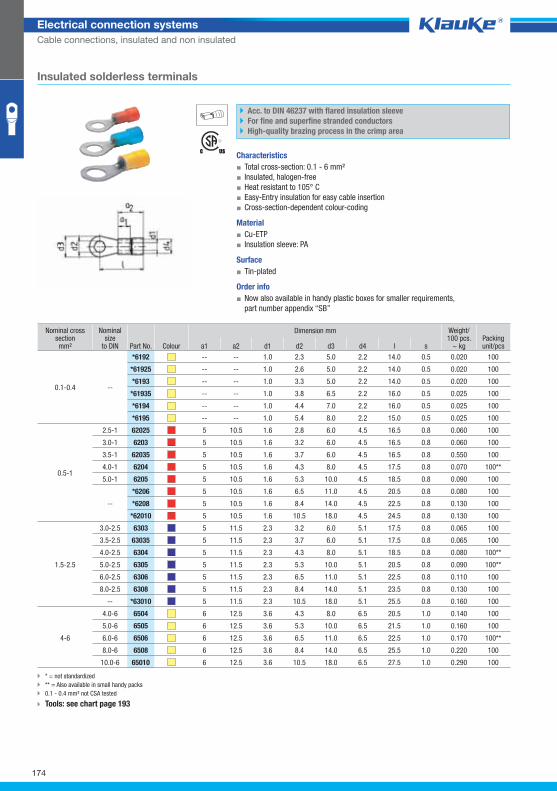
6192grp
174
Electrical connection systems
Cable connections, insulated and non insulated
Nominal cross section mm²
Nominal size
to DIN Part No. Colour
Dimension mm Weight/100 pcs.
~ kg Packing unit/pcs a1 a2 d1 d2 d3 d4 l s
0.1-0.4 --
*6192 -- -- 1.0 2.3 5.0 2.2 14.0 0.5 0.020 100
*61925 -- -- 1.0 2.6 5.0 2.2 14.0 0.5 0.020 100
*6193 -- -- 1.0 3.3 5.0 2.2 14.0 0.5 0.020 100
*61935 -- -- 1.0 3.8 6.5 2.2 16.0 0.5 0.025 100
*6194 -- -- 1.0 4.4 7.0 2.2 16.0 0.5 0.025 100
*6195 -- -- 1.0 5.4 8.0 2.2 15.0 0.5 0.025 100
0.5-1
2.5-1 62025 5 10.5 1.6 2.8 6.0 4.5 16.5 0.8 0.060 100
3.0-1 6203 5 10.5 1.6 3.2 6.0 4.5 16.5 0.8 0.060 100
3.5-1 62035 5 10.5 1.6 3.7 6.0 4.5 16.5 0.8 0.550 100
4.0-1 6204 5 10.5 1.6 4.3 8.0 4.5 17.5 0.8 0.070 100**
5.0-1 6205 5 10.5 1.6 5.3 10.0 4.5 18.5 0.8 0.090 100
--
*6206 5 10.5 1.6 6.5 11.0 4.5 20.5 0.8 0.080 100
*6208 5 10.5 1.6 8.4 14.0 4.5 22.5 0.8 0.130 100
*62010 5 10.5 1.6 10.5 18.0 4.5 24.5 0.8 0.130 100
1.5-2.5
3.0-2.5 6303 5 11.5 2.3 3.2 6.0 5.1 17.5 0.8 0.065 100
3.5-2.5 63035 5 11.5 2.3 3.7 6.0 5.1 17.5 0.8 0.065 100
4.0-2.5 6304 5 11.5 2.3 4.3 8.0 5.1 18.5 0.8 0.080 100**
5.0-2.5 6305 5 11.5 2.3 5.3 10.0 5.1 20.5 0.8 0.090 100**
6.0-2.5 6306 5 11.5 2.3 6.5 11.0 5.1 22.5 0.8 0.110 100
8.0-2.5 6308 5 11.5 2.3 8.4 14.0 5.1 23.5 0.8 0.130 100
-- *63010 5 11.5 2.3 10.5 18.0 5.1 25.5 0.8 0.160 100
4-6
4.0-6 6504 6 12.5 3.6 4.3 8.0 6.5 20.5 1.0 0.140 100
5.0-6 6505 6 12.5 3.6 5.3 10.0 6.5 21.5 1.0 0.160 100
6.0-6 6506 6 12.5 3.6 6.5 11.0 6.5 22.5 1.0 0.170 100**
8.0-6 6508 6 12.5 3.6 8.4 14.0 6.5 25.5 1.0 0.220 100
10.0-6 65010 6 12.5 3.6 10.5 18.0 6.5 27.5 1.0 0.290 100
Acc. to DIN 46237 with flared insulation sleeve
For fine and superfine stranded conductors
High-quality brazing process in the crimp area
Characteristics
▪ Total cross-section: 0.1 - 6 mm²
▪ Insulated, halogen-free
▪ Heat resistant to 105° C
▪ Easy-Entry insulation for easy cable insertion
▪ Cross-section-dependent colour-coding
Material
▪ Cu-ETP
▪ Insulation sleeve: PA
Surface
▪ Tin-plated
Order info
▪ Now also available in handy plastic boxes for smaller requirements,
part number appendix “SB”
Insulated solderless terminals
* = not standardized
** = Also available in small handy packs
0.1 - 0.4 mm² not CSA tested
Tools: see chart page 193
Klauke Hauptkatalog EN_DIN A5.indb 174 07.10.2014 12:17:25
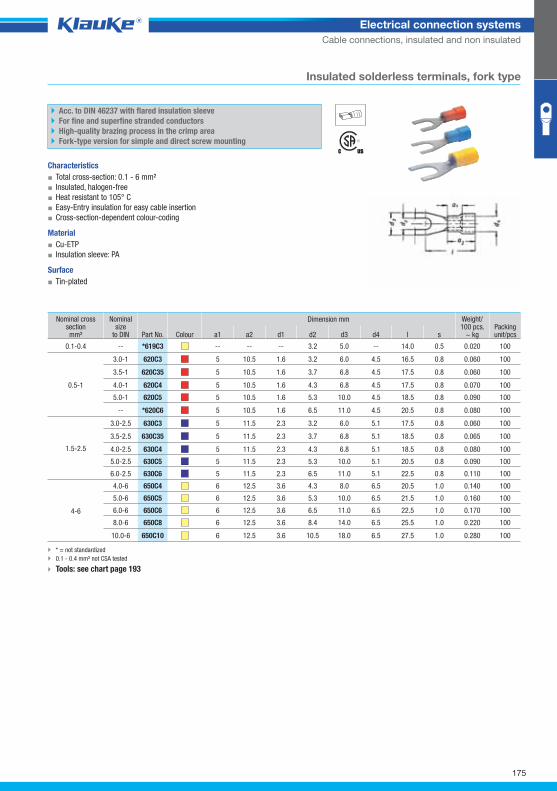
619c3grp
175
Electrical connection systems
Cable connections, insulated and non insulated
Nominal cross section mm²
Nominal size
to DIN Part No. Colour
Dimension mm Weight/100 pcs.
~ kg Packing unit/pcs a1 a2 d1 d2 d3 d4 l s
0.1-0.4 -- *619C3 -- -- -- 3.2 5.0 -- 14.0 0.5 0.020 100
0.5-1
3.0-1 620C3 5 10.5 1.6 3.2 6.0 4.5 16.5 0.8 0.060 100
3.5-1 620C35 5 10.5 1.6 3.7 6.8 4.5 17.5 0.8 0.060 100
4.0-1 620C4 5 10.5 1.6 4.3 6.8 4.5 17.5 0.8 0.070 100
5.0-1 620C5 5 10.5 1.6 5.3 10.0 4.5 18.5 0.8 0.090 100
-- *620C6 5 10.5 1.6 6.5 11.0 4.5 20.5 0.8 0.080 100
1.5-2.5
3.0-2.5 630C3 5 11.5 2.3 3.2 6.0 5.1 17.5 0.8 0.060 100
3.5-2.5 630C35 5 11.5 2.3 3.7 6.8 5.1 18.5 0.8 0.065 100
4.0-2.5 630C4 5 11.5 2.3 4.3 6.8 5.1 18.5 0.8 0.080 100
5.0-2.5 630C5 5 11.5 2.3 5.3 10.0 5.1 20.5 0.8 0.090 100
6.0-2.5 630C6 5 11.5 2.3 6.5 11.0 5.1 22.5 0.8 0.110 100
4-6
4.0-6 650C4 6 12.5 3.6 4.3 8.0 6.5 20.5 1.0 0.140 100
5.0-6 650C5 6 12.5 3.6 5.3 10.0 6.5 21.5 1.0 0.160 100
6.0-6 650C6 6 12.5 3.6 6.5 11.0 6.5 22.5 1.0 0.170 100
8.0-6 650C8 6 12.5 3.6 8.4 14.0 6.5 25.5 1.0 0.220 100
10.0-6 650C10 6 12.5 3.6 10.5 18.0 6.5 27.5 1.0 0.280 100
Insulated solderless terminals, fork type
Acc. to DIN 46237 with flared insulation sleeve
For fine and superfine stranded conductors
High-quality brazing process in the crimp area
Fork-type version for simple and direct screw mounting
Characteristics
▪ Total cross-section: 0.1 - 6 mm²
▪ Insulated, halogen-free
▪ Heat resistant to 105° C
▪ Easy-Entry insulation for easy cable insertion
▪ Cross-section-dependent colour-coding
Material
▪ Cu-ETP
▪ Insulation sleeve: PA
Surface
▪ Tin-plated
* = not standardized
0.1 - 0.4 mm² not CSA tested
Tools: see chart page 193
Klauke Hauptkatalog EN_DIN A5.indb 175 07.10.2014 12:17:26
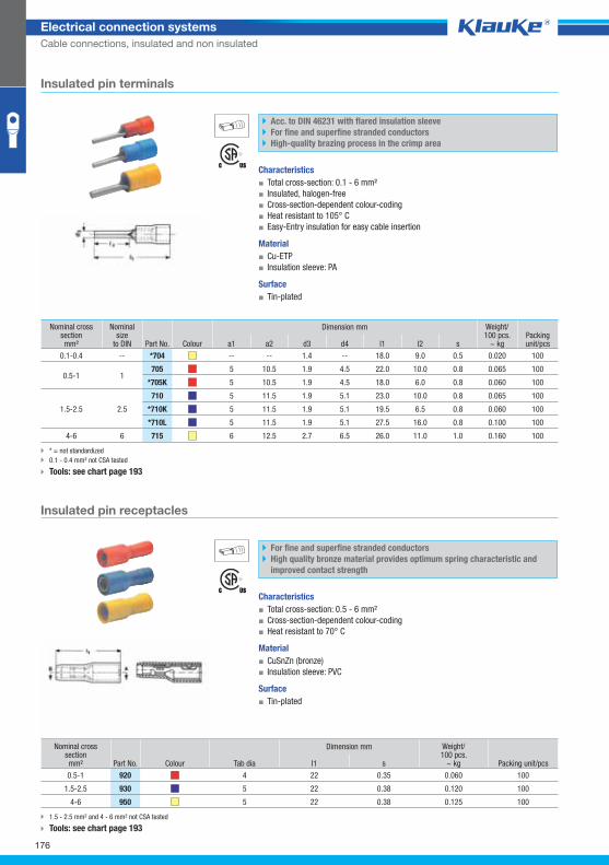
704grp
920grp
176
Electrical connection systems
Cable connections, insulated and non insulated
Nominal cross section mm²
Nominal size
to DIN Part No. Colour
Dimension mm Weight/100 pcs.
~ kg Packing unit/pcs a1 a2 d3 d4 l1 l2 s
0.1-0.4 -- *704 -- -- 1.4 -- 18.0 9.0 0.5 0.020 100
0.5-1 1 705 5 10.5 1.9 4.5 22.0 10.0 0.8 0.065 100
*705K 5 10.5 1.9 4.5 18.0 6.0 0.8 0.060 100
1.5-2.5 2.5
710 5 11.5 1.9 5.1 23.0 10.0 0.8 0.065 100
*710K 5 11.5 1.9 5.1 19.5 6.5 0.8 0.060 100
*710L 5 11.5 1.9 5.1 27.5 16.0 0.8 0.100 100
4-6 6 715 6 12.5 2.7 6.5 26.0 11.0 1.0 0.160 100
Nominal cross section mm² Part No. Colour
Dimension mm Weight/100 pcs.
~ kg Packing unit/pcs Tab dia l1 s
0.5-1 920 4 22 0.35 0.060 100
1.5-2.5 930 5 22 0.38 0.120 100
4-6 950 5 22 0.38 0.125 100
Insulated pin terminals
Acc. to DIN 46231 with flared insulation sleeve
For fine and superfine stranded conductors
High-quality brazing process in the crimp area
Characteristics
▪ Total cross-section: 0.1 - 6 mm²
▪ Insulated, halogen-free
▪ Cross-section-dependent colour-coding
▪ Heat resistant to 105° C
▪ Easy-Entry insulation for easy cable insertion
Material
▪ Cu-ETP
▪ Insulation sleeve: PA
Surface
▪ Tin-plated
* = not standardized
0.1 - 0.4 mm² not CSA tested
Tools: see chart page 193
Insulated pin receptacles
For fine and superfine stranded conductors
High quality bronze material provides optimum spring characteristic and
improved contact strength
Characteristics
▪ Total cross-section: 0.5 - 6 mm²
▪ Cross-section-dependent colour-coding
▪ Heat resistant to 70° C
Material
▪ CuSnZn (bronze)
▪ Insulation sleeve: PVC
Surface
▪ Tin-plated
1.5 - 2.5 mm² and 4 - 6 mm² not CSA tested
Tools: see chart page 193
Klauke Hauptkatalog EN_DIN A5.indb 176 07.10.2014 12:17:26

1020grp
920vgrp
177
Electrical connection systems
Cable connections, insulated and non insulated
Nominal cross section mm² Part No. Colour
Dimension mm Weight/100 pcs.
~ kg Packing unit/pcs Tab dia. l1 l2 s
0.5-1 1020 4 22 9 0.38 0.060 100
1.5-2.5 1030 5 22 9 0.38 0.075 100
4-6 1050 5 22 9 0.40 0.110 100
Nominal cross section mm² Part No. Colour
Dimension mm Weight/100 pcs.
~ kg Packing unit/pcs Tab dia. l1 s
0.5-1 920V 4 24 0.38 0.065 100
4-6 950V 5 27 0.40 0.150 100
Insulated pin connectors
For fine and superfine stranded conductors
Characteristics
▪ Total cross-section: 0.5 - 6 mm²
▪ Cross-section-dependent colour-coding
▪ Heat resistant to 70° C
Material
▪ CuZn (brass)
▪ Insulation sleeve: PVC
Surface
▪ Tin-plated to protect against corrosion
1.5 - 2.5 mm² and 4 - 6 mm² not CSA tested
Tools: see chart page 193
Insulated pin receptacles, fully insulated
For fine and superfine stranded conductors
High quality bronze material provides optimum spring characteristic and
improved contact strength
Characteristics
▪ Total cross-section: 0.5 - 6 mm²
▪ Insulated, halogen-free
▪ Cross-section-dependent colour-coding
▪ Heat resistant to 105° C
Material
▪ CuSnZn (bronze)
▪ Insulation sleeve: PA
Surface
▪ Tin-plated
4 - 6 mm² not CSA tested
Tools: see chart page 193
Klauke Hauptkatalog EN_DIN A5.indb 177 07.10.2014 12:17:27
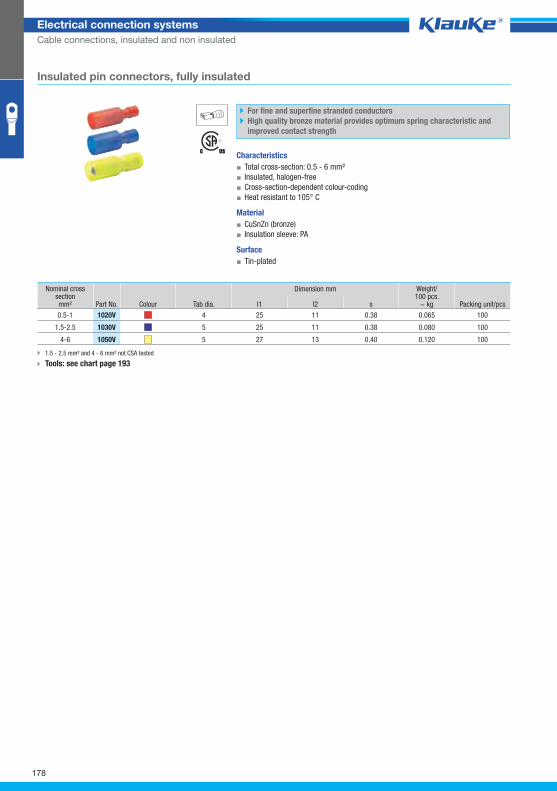
1020vgrp
178
Electrical connection systems
Cable connections, insulated and non insulated
Nominal cross section mm² Part No. Colour
Dimension mm Weight/100 pcs.
~ kg Packing unit/pcs Tab dia. l1 l2 s
0.5-1 1020V 4 25 11 0.38 0.065 100
1.5-2.5 1030V 5 25 11 0.38 0.080 100
4-6 1050V 5 27 13 0.40 0.120 100
Insulated pin connectors, fully insulated
For fine and superfine stranded conductors
High quality bronze material provides optimum spring characteristic and
improved contact strength
Characteristics
▪ Total cross-section: 0.5 - 6 mm²
▪ Insulated, halogen-free
▪ Cross-section-dependent colour-coding
▪ Heat resistant to 105° C
Material
▪ CuSnZn (bronze)
▪ Insulation sleeve: PA
Surface
▪ Tin-plated
1.5 - 2.5 mm² and 4 - 6 mm² not CSA tested
Tools: see chart page 193
Klauke Hauptkatalog EN_DIN A5.indb 178 07.10.2014 12:17:27
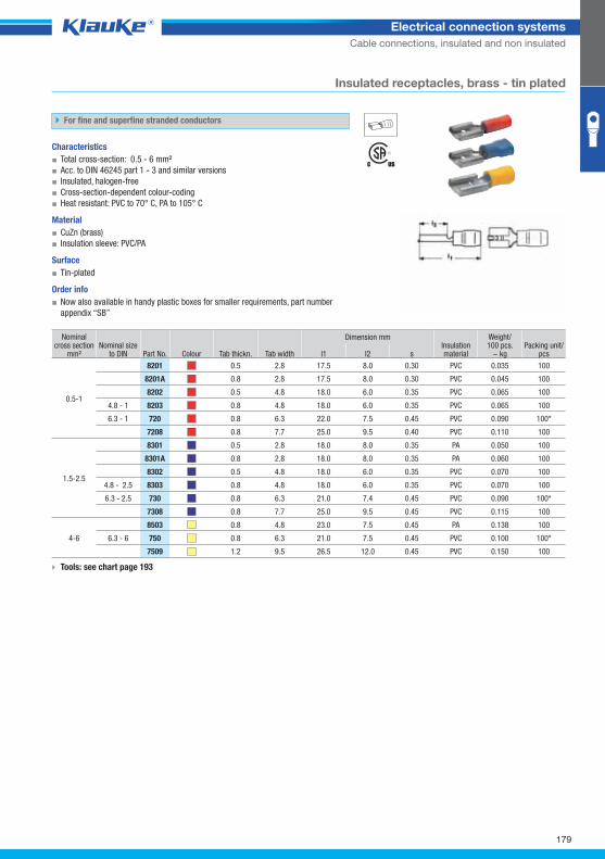
8201grp
179
Electrical connection systems
Cable connections, insulated and non insulated
Nominal cross section
mm² Nominal size
to DIN Part No. Colour Tab thickn. Tab width
Dimension mm Insulation material
Weight/100 pcs.
~ kg Packing unit/
pcs l1 l2 s
0.5-1
8201 0.5 2.8 17.5 8.0 0.30 PVC 0.035 100
8201A 0.8 2.8 17.5 8.0 0.30 PVC 0.045 100
8202 0.5 4.8 18.0 6.0 0.35 PVC 0.065 100
4.8 - 1 8203 0.8 4.8 18.0 6.0 0.35 PVC 0.065 100
6.3 - 1 720 0.8 6.3 22.0 7.5 0.45 PVC 0.090 100*
7208 0.8 7.7 25.0 9.5 0.40 PVC 0.110 100
1.5-2.5
8301 0.5 2.8 18.0 8.0 0.35 PA 0.050 100
8301A 0.8 2.8 18.0 8.0 0.35 PA 0.060 100
8302 0.5 4.8 18.0 6.0 0.35 PVC 0.070 100
4.8 - 2.5 8303 0.8 4.8 18.0 6.0 0.35 PVC 0.070 100
6.3 - 2.5 730 0.8 6.3 21.0 7.4 0.45 PVC 0.090 100*
7308 0.8 7.7 25.0 9.5 0.45 PVC 0.115 100
4-6
8503 0.8 4.8 23.0 7.5 0.45 PA 0.138 100
6.3 - 6 750 0.8 6.3 21.0 7.5 0.45 PVC 0.100 100*
7509 1.2 9.5 26.5 12.0 0.45 PVC 0.150 100
Insulated receptacles, brass - tin plated
For fine and superfine stranded conductors
Characteristics
▪ Total cross-section: 0.5 - 6 mm²
▪ Acc. to DIN 46245 part 1 - 3 and similar versions
▪ Insulated, halogen-free
▪ Cross-section-dependent colour-coding
▪ Heat resistant: PVC to 70° C, PA to 105° C
Material
▪ CuZn (brass)
▪ Insulation sleeve: PVC/PA
Surface
▪ Tin-plated
Order info
▪ Now also available in handy plastic boxes for smaller requirements, part number
appendix “SB”
Tools: see chart page 193
Klauke Hauptkatalog EN_DIN A5.indb 179 07.10.2014 12:17:27
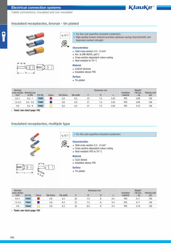
720bzgrp
720azgrp
180
Electrical connection systems
Cable connections, insulated and non insulated
Nominal cross section
mm² Nominal size
to DIN Part No. Colour Tab thickn. Tab width
Dimension mm Insulation material
Weight/100 pcs.
~ kg Packing unit/
pcs l1 l2 s
0,5-1 6,3 - 1 720BZ 0,8 6,3 22 7,5 0,45 PVC 0,09 100
1,5-2,5 6,3 - 2,5 730BZ 0,8 6,3 21 7,4 0,45 PVC 0,09 100
4-6 6,3 - 6 750BZ 0,8 6,3 21 7,5 0,45 PVC 0,10 100
Nominal cross section
mm² Part No. Colour Tab thickn. Tab width
Dimension mm Insulation material
Weight/100 pcs.
~ kg Packing unit/
pcs l1 l2 l3 s
0.5-1 720AZ 0.8 6.3 22 7.5 8 0.4 PVC 0.11 100
1.5-2.5 730AZ 0.8 6.3 22 7.5 8 0.4 PVC 0.11 100
4-6 750AZ 0.8 6.3 25 8.0 8 0.4 PVC 0.18 100
Insulated receptacles, bronze - tin plated
For fine and superfine stranded conductors
High quality bronze material provides optimum spring characteristic and
improved contact strength
Characteristics
▪ Total cross-section: 0.5 - 6 mm²
▪ Acc. to DIN 46245, part 3
▪ Cross-section-dependent colour-coding
▪ Heat resistant to 70° C
Material
▪ CuSnZn (bronze)
▪ Insulation sleeve: PVC
Surface
▪ Tin-plated
Tools: see chart page 193
Insulated receptacles, multiple type
For fine and superfine stranded conductors
Characteristics
▪ Total cross-section: 0.5 - 6 mm²
▪ Cross-section-dependent colour-coding
▪ Heat resistant: PVC to 70° C
Material
▪ CuZn (brass)
▪ Insulation sleeve: PVC
Surface
▪ Tin-plated
Tools: see chart page 193
Klauke Hauptkatalog EN_DIN A5.indb 180 07.10.2014 12:17:28
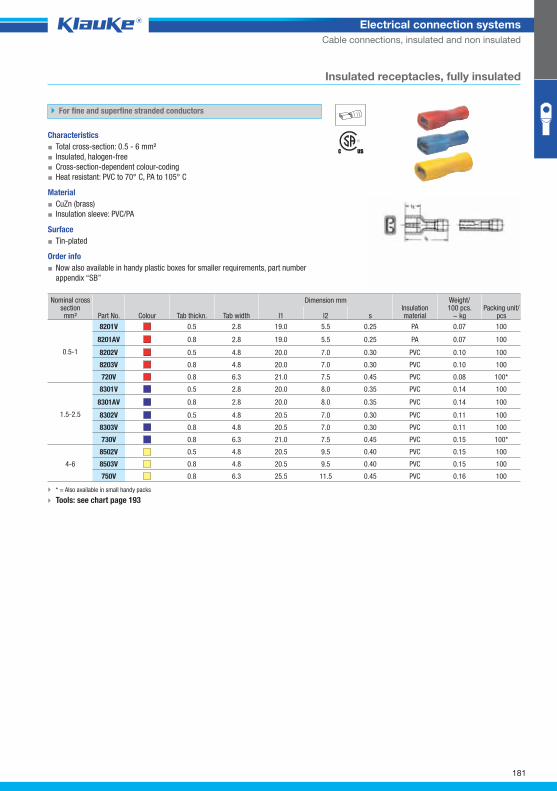
8201vgrp
181
Electrical connection systems
Cable connections, insulated and non insulated
Nominal cross section mm² Part No. Colour Tab thickn. Tab width
Dimension mm Insulation material
Weight/100 pcs.
~ kg Packing unit/
pcs l1 l2 s
0.5-1
8201V 0.5 2.8 19.0 5.5 0.25 PA 0.07 100
8201AV 0.8 2.8 19.0 5.5 0.25 PA 0.07 100
8202V 0.5 4.8 20.0 7.0 0.30 PVC 0.10 100
8203V 0.8 4.8 20.0 7.0 0.30 PVC 0.10 100
720V 0.8 6.3 21.0 7.5 0.45 PVC 0.08 100*
1.5-2.5
8301V 0.5 2.8 20.0 8.0 0.35 PVC 0.14 100
8301AV 0.8 2.8 20.0 8.0 0.35 PVC 0.14 100
8302V 0.5 4.8 20.5 7.0 0.30 PVC 0.11 100
8303V 0.8 4.8 20.5 7.0 0.30 PVC 0.11 100
730V 0.8 6.3 21.0 7.5 0.45 PVC 0.15 100*
4-6
8502V 0.5 4.8 20.5 9.5 0.40 PVC 0.15 100
8503V 0.8 4.8 20.5 9.5 0.40 PVC 0.15 100
750V 0.8 6.3 25.5 11.5 0.45 PVC 0.16 100
Insulated receptacles, fully insulated
For fine and superfine stranded conductors
Characteristics
▪ Total cross-section: 0.5 - 6 mm²
▪ Insulated, halogen-free
▪ Cross-section-dependent colour-coding
▪ Heat resistant: PVC to 70° C, PA to 105° C
Material
▪ CuZn (brass)
▪ Insulation sleeve: PVC/PA
Surface
▪ Tin-plated
Order info
▪ Now also available in handy plastic boxes for smaller requirements, part number
appendix “SB”
* = Also available in small handy packs
Tools: see chart page 193
Klauke Hauptkatalog EN_DIN A5.indb 181 07.10.2014 12:17:28
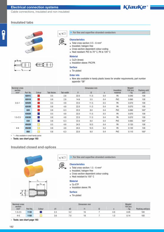
8201cgrp
1130grp
182
Electrical connection systems
Cable connections, insulated and non insulated
Nominal cross section mm² Part No. Colour Tab thickn. Tab width
Dimension mm Insulation material
Weight/100 pcs.
~ kg Packing unit/
pcs l1 l2 s
0.5-1
8201C 0.5 2.8 22.0 11.5 0.4 PA 0.040 100
8201B 0.8 2.8 14.6 5.5 0.4 PVC 0.060 100
8202B 0.5 4.8 22.0 11.5 0.5 PA 0.070 100
8203B 0.8 4.8 22.0 11.5 0.4 PA 0.070 100
820 0.8 6.3 22.0 8.0 0.4 PVC 0.060 100*
1.5-2.5
8302B 0.5 4.8 22.0 11.5 0.5 PA 0.070 100
8303B 0.8 4.8 22.0 11.5 0.4 PA 0.070 100
830 0.8 6.3 22.0 8.0 0.4 PVC 0.065 100*
4-6
8502B 0.5 4.8 24.5 10.5 0.4 PA 0.120 100
8503B 0.8 4.8 24.5 10.5 0.4 PA 0.120 100
850 0.8 6.3 22.0 8.0 0.4 PVC 0.110 100*
Nominal cross section mm² Part No. Colour
Dimension mm Weight/100 pcs.
~ kg Packing unit/pcs d1 d2 l1 l2 s
1.5-2.5 1130 2.3 5.2 16 7 0.8 0.05 100
4-6 1150 3.6 7.0 18 7 1.0 0.14 100
Insulated tabs
For fine and superfine stranded conductors
Characteristics
▪ Total cross-section: 0.5 - 6 mm²
▪ Insulated, halogen-free
▪ Cross-section-dependent colour-coding
▪ Heat resistant: PVC to 70° C, PA to 105° C
Material
▪ CuZn (brass)
▪ Insulation sleeve: PVC/PA
Surface
▪ Tin-plated
Order info
▪ Now also available in handy plastic boxes for smaller requirements, part number
appendix “SB”
* = Also available in small handy packs
Tools: see chart page 193
Insulated closed end-splices
For fine and superfine stranded conductors
Characteristics
▪ Total cross-section: 1.5 - 6 mm²
▪ Insulated, halogen-free
▪ Cross-section-dependent colour-coding
▪ Heat resistant to 105° C
Material
▪ Cu-ETP
▪ Insulation sleeve: PA
Surface
▪ Tin-plated
Tools: see chart page 193
Klauke Hauptkatalog EN_DIN A5.indb 182 07.10.2014 12:17:29
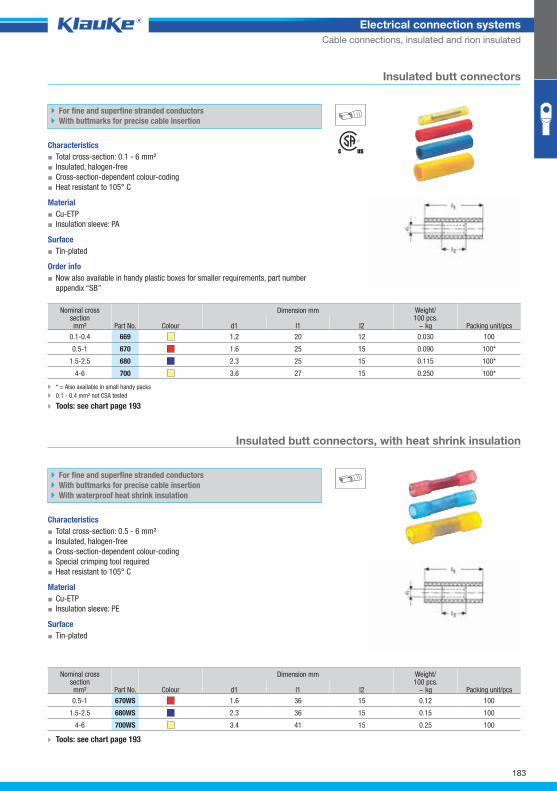
669grp
670wsgrp
183
Electrical connection systems
Cable connections, insulated and non insulated
Nominal cross section mm² Part No. Colour
Dimension mm Weight/100 pcs.
~ kg Packing unit/pcs d1 l1 l2
0.1-0.4 669 1.2 20 12 0.030 100
0.5-1 670 1.6 25 15 0.090 100*
1.5-2.5 680 2.3 25 15 0.115 100*
4-6 700 3.6 27 15 0.250 100*
Nominal cross section mm² Part No. Colour
Dimension mm Weight/100 pcs.
~ kg Packing unit/pcs d1 l1 l2
0.5-1 670WS 1.6 36 15 0.12 100
1.5-2.5 680WS 2.3 36 15 0.15 100
4-6 700WS 3.4 41 15 0.25 100
Tools: see chart page 193
* = Also available in small handy packs
0.1 - 0.4 mm² not CSA tested
Tools: see chart page 193
Insulated butt connectors, with heat shrink insulation
For fine and superfine stranded conductors
With buttmarks for precise cable insertion
With waterproof heat shrink insulation
Characteristics
▪ Total cross-section: 0.5 - 6 mm²
▪ Insulated, halogen-free
▪ Cross-section-dependent colour-coding
▪ Special crimping tool required
▪ Heat resistant to 105° C
Material
▪ Cu-ETP
▪ Insulation sleeve: PE
Surface
▪ Tin-plated
Insulated butt connectors
For fine and superfine stranded conductors
With buttmarks for precise cable insertion
Characteristics
▪ Total cross-section: 0.1 - 6 mm²
▪ Insulated, halogen-free
▪ Cross-section-dependent colour-coding
▪ Heat resistant to 105° C
Material
▪ Cu-ETP
▪ Insulation sleeve: PA
Surface
▪ Tin-plated
Order info
▪ Now also available in handy plastic boxes for smaller requirements, part number
appendix “SB”
Klauke Hauptkatalog EN_DIN A5.indb 183 07.10.2014 12:17:29
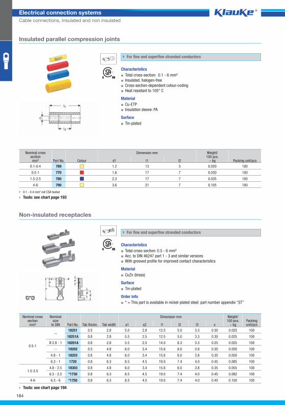
769grp
18251grp
184
Electrical connection systems
Cable connections, insulated and non insulated
Nominal cross section mm² Part No. Colour
Dimension mm Weight/100 pcs.
~ kg Packing unit/pcs d1 l1 l2
0.1-0.4 769 1.2 13 5 0.020 100
0.5-1 770 1.6 17 7 0.030 100
1.5-2.5 780 2.3 17 7 0.035 100
4-6 790 3.6 21 7 0.105 100
Nominal cross section mm²
Nominal size
to DIN Part No. Tab thickn. Tab width
Dimension mm Weight/100 pcs.
~ kg Packing unit/pcs a1 a2 l1 l2 l3 s
0.5-1
-- 18251 0.5 2.8 5.0 2.8 12.5 5.0 3.3 0.30 0.025 100
18251A 0.8 2.8 5.5 2.5 12.5 5.0 3.3 0.30 0.025 100
B 2.8 - 1 18201A 0.8 2.8 5.5 2.5 14.0 6.3 3.3 0.25 0.025 100
-- 18202 0.5 4.8 6.0 3.4 15.6 6.0 3.8 0.35 0.050 100
4.8 - 1 18203 0.8 4.8 6.0 3.4 15.6 6.0 3.8 0.35 0.050 100
6.3 - 1 1720 0.8 6.3 8.5 4.5 19.0 7.4 4.0 0.45 0.085 100
1.5-2.5 4.8 - 2.5 18303 0.8 4.8 6.0 3.4 15.6 6.0 3.8 0.35 0.055 100
6.3 - 2.5 *1730 0.8 6.3 8.5 4.5 19.0 7.4 4.0 0.45 0.082 100
4-6 6.3 - 6 *1750 0.8 6.3 8.5 4.5 19.0 7.4 4.0 0.45 0.100 100
0.1 - 0.4 mm² not CSA tested
Tools: see chart page 193
Tools: see chart page 194
Insulated parallel compression joints
For fine and superfine stranded conductors
Characteristics
▪ Total cross-section: 0.1 - 6 mm²
▪ Insulated, halogen-free
▪ Cross-section-dependent colour-coding
▪ Heat resistant to 105° C
Material
▪ Cu-ETP
▪ Insulation sleeve: PA
Surface
▪ Tin-plated
Non-insulated receptacles
For fine and superfine stranded conductors
Characteristics
▪ Total cross-section: 0.5 - 6 mm²
▪ Acc. to DIN 46247 part 1 - 3 and similar versions
▪ With grooved profile for improved contact characteristics
Material
▪ CuZn (brass)
Surface
▪ Tin-plated
Order info
▪ * = This part is available in nickel-plated steel; part number appendix “ST”
Klauke Hauptkatalog EN_DIN A5.indb 184 07.10.2014 12:17:30
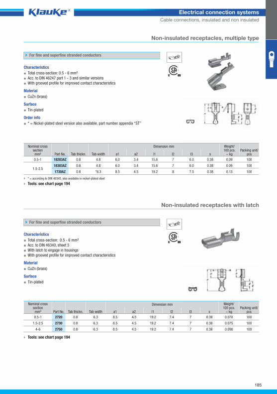
18203azgrp
2720grp
185
Electrical connection systems
Cable connections, insulated and non insulated
Nominal cross section mm² Part No. Tab thickn. Tab width
Dimension mm Weight/100 pcs.
~ kg Packing unit/
pcs a1 a2 l1 l2 l3 s
0.5-1 18203AZ 0.8 4.8 6.0 3.4 15.6 7 6.0 0.38 0.09 100
1.5-2.5 18303AZ 0.8 4.8 6.0 3.4 15.6 7 6.0 0.38 0.09 100
1730AZ 0.8 *6.3 8.5 4.5 19.2 8 7.5 0.38 0.13 100
Non-insulated receptacles, multiple type
For fine and superfine stranded conductors
Characteristics
▪ Total cross-section: 0.5 - 6 mm²
▪ Acc. to DIN 46247 part 1 - 3 and similar versions
▪ With grooved profile for improved contact characteristics
Material
▪ CuZn (brass)
Surface
▪ Tin-plated
Order info
▪ * = Nickel-plated steel version also available, part number appendix “ST”
* = according to DIN 46345, also available in nickel-plated steel
Tools: see chart page 194
Non-insulated receptacles with latch
For fine and superfine stranded conductors
Characteristics
▪ Total cross-section: 0.5 - 6 mm²
▪ Acc. to DIN 46340, sheet 3
▪ With latch to engage in housings
▪ With grooved profile for improved contact characteristics
Material
▪ CuZn (brass)
Surface
▪ Tin-plated
Nominal cross section mm² Part No. Tab thickn. Tab width
Dimension mm Weight/100 pcs.
~ kg Packing unit/
pcs a1 a2 l1 l2 l3 s
0.5-1 2720 0.8 6.3 8.5 4.5 19.2 7.4 7 0.38 0.070 100
1.5-2.5 2730 0.8 6.3 8.5 4.5 19.2 7.4 7 0.38 0.075 100
4-6 2750 0.8 6.3 8.5 4.5 19.2 7.4 7 0.38 0.090 100
Tools: see chart page 194
Klauke Hauptkatalog EN_DIN A5.indb 185 07.10.2014 12:17:31
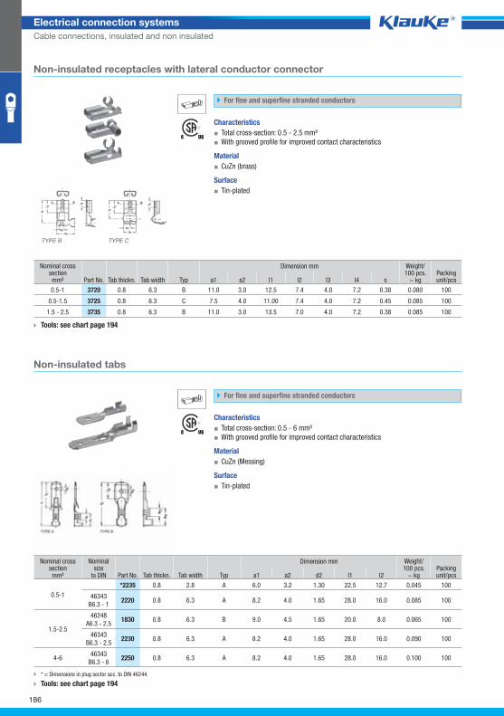
3720grp
2235grp
186
Electrical connection systems
Cable connections, insulated and non insulated
Nominal cross section mm² Part No. Tab thickn. Tab width Typ
Dimension mm Weight/100 pcs.
~ kg Packing unit/pcs a1 a2 l1 l2 l3 l4 s
0.5-1 3720 0.8 6.3 B 11.0 3.0 12.5 7.4 4.0 7.2 0.38 0.080 100
0.5-1.5 3725 0.8 6.3 C 7.5 4.0 11.00 7.4 4.0 7.2 0.45 0.085 100
1.5 - 2.5 3735 0.8 6.3 B 11.0 3.0 13.5 7.0 4.0 7.2 0.38 0.085 100
Non-insulated tabs
For fine and superfine stranded conductors
Characteristics
▪ Total cross-section: 0.5 - 6 mm²
▪ With grooved profile for improved contact characteristics
Material
▪ CuZn (Messing)
Surface
▪ Tin-plated
Nominal cross section mm²
Nominal size
to DIN Part No. Tab thickn. Tab width Typ
Dimension mm Weight/100 pcs.
~ kg Packing unit/pcs a1 a2 d2 l1 l2
0.5-1
*2235 0.8 2.8 A 6.0 3.2 1.30 22.5 12.7 0.045 100
46343
B6.3 - 1 2220 0.8 6.3 A 8.2 4.0 1.65 28.0 16.0 0.085 100
1.5-2.5
46248
A6.3 - 2.5 1830 0.8 6.3 B 9.0 4.5 1.65 20.0 8.0 0.065 100
46343
B6.3 - 2.5 2230 0.8 6.3 A 8.2 4.0 1.65 28.0 16.0 0.090 100
4-6 46343
B6.3 - 6 2250 0.8 6.3 A 8.2 4.0 1.65 28.0 16.0 0.100 100
Non-insulated receptacles with lateral conductor connector
For fine and superfine stranded conductors
Characteristics
▪ Total cross-section: 0.5 - 2.5 mm²
▪ With grooved profile for improved contact characteristics
Material
▪ CuZn (brass)
Surface
▪ Tin-plated
Tools: see chart page 194
* = Dimensions in plug sector acc. to DIN 46244
Tools: see chart page 194
Klauke Hauptkatalog EN_DIN A5.indb 186 07.10.2014 12:17:31
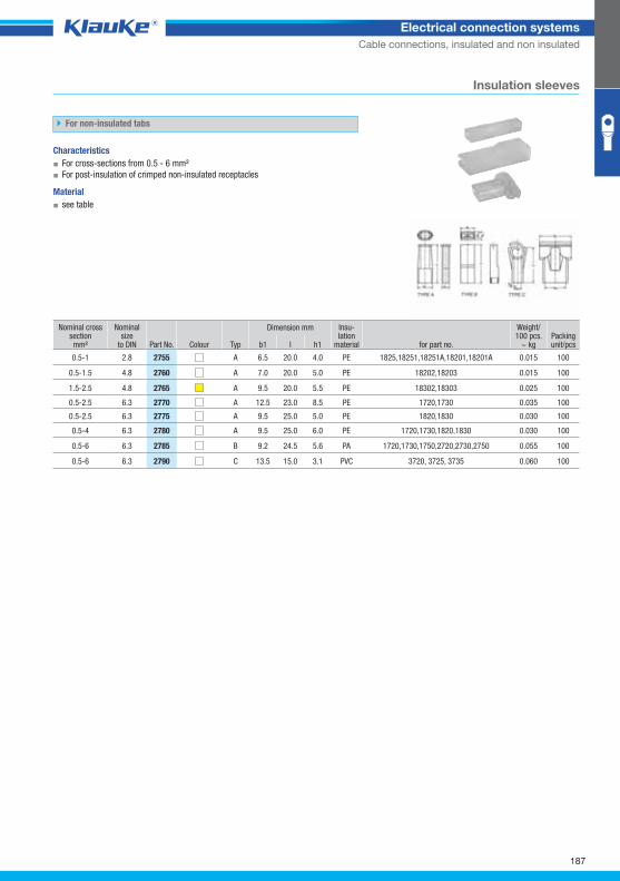
2755grp
187
Electrical connection systems
Cable connections, insulated and non insulated
Nominal cross section mm²
Nominal size
to DIN Part No. Colour Typ
Dimension mm Insu-lation
material for part no.
Weight/100 pcs.
~ kg Packing unit/pcs b1 l h1
0.5-1 2.8 2755 A 6.5 20.0 4.0 PE 1825,18251,18251A,18201,18201A 0.015 100
0.5-1.5 4.8 2760 A 7.0 20.0 5.0 PE 18202,18203 0.015 100
1.5-2.5 4.8 2765 A 9.5 20.0 5.5 PE 18302,18303 0.025 100
0.5-2.5 6.3 2770 A 12.5 23.0 8.5 PE 1720,1730 0.035 100
0.5-2.5 6.3 2775 A 9.5 25.0 5.0 PE 1820,1830 0.030 100
0.5-4 6.3 2780 A 9.5 25.0 6.0 PE 1720,1730,1820,1830 0.030 100
0.5-6 6.3 2785 B 9.2 24.5 5.6 PA 1720,1730,1750,2720,2730,2750 0.055 100
0.5-6 6.3 2790 C 13.5 15.0 3.1 PVC 3720, 3725, 3735 0.060 100
Insulation sleeves
For non-insulated tabs
Characteristics
▪ For cross-sections from 0.5 - 6 mm²
▪ For post-insulation of crimped non-insulated receptacles
Material
▪ see table
Klauke Hauptkatalog EN_DIN A5.indb 187 07.10.2014 12:17:32
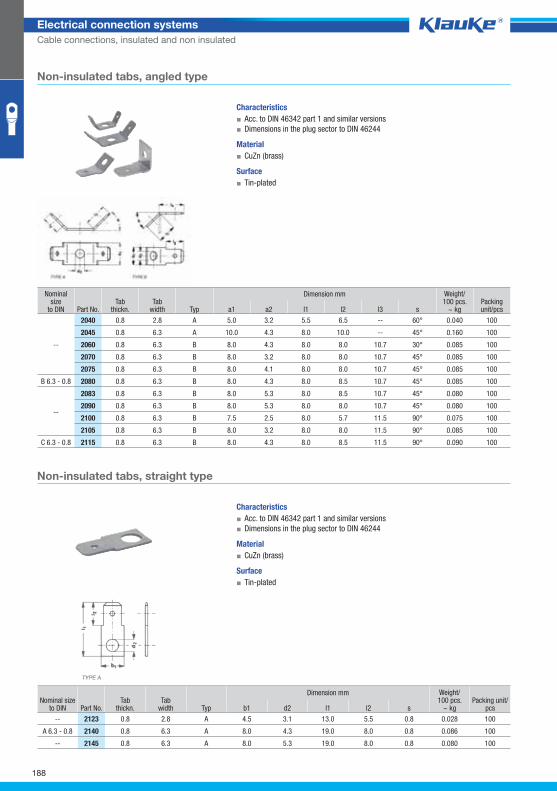
2040grp
2123grp
188
Electrical connection systems
Cable connections, insulated and non insulated
Nominal size
to DIN Part No. Tab
thickn. Tab
width Typ
Dimension mm Weight/100 pcs.
~ kg Packing unit/pcs a1 a2 l1 l2 l3 s
--
2040 0.8 2.8 A 5.0 3.2 5.5 6.5 -- 60° 0.040 100
2045 0.8 6.3 A 10.0 4.3 8.0 10.0 -- 45° 0.160 100
2060 0.8 6.3 B 8.0 4.3 8.0 8.0 10.7 30° 0.085 100
2070 0.8 6.3 B 8.0 3.2 8.0 8.0 10.7 45° 0.085 100
2075 0.8 6.3 B 8.0 4.1 8.0 8.0 10.7 45° 0.085 100
B 6.3 - 0.8 2080 0.8 6.3 B 8.0 4.3 8.0 8.5 10.7 45° 0.085 100
--
2083 0.8 6.3 B 8.0 5.3 8.0 8.5 10.7 45° 0.080 100
2090 0.8 6.3 B 8.0 5.3 8.0 8.0 10.7 45° 0.080 100
2100 0.8 6.3 B 7.5 2.5 8.0 5.7 11.5 90° 0.075 100
2105 0.8 6.3 B 8.0 3.2 8.0 8.0 11.5 90° 0.085 100
C 6.3 - 0.8 2115 0.8 6.3 B 8.0 4.3 8.0 8.5 11.5 90° 0.090 100
Nominal sizeto DIN Part No.
Tab thickn.
Tab width Typ
Dimension mm Weight/100 pcs.
~ kg Packing unit/
pcs b1 d2 l1 l2 s
-- 2123 0.8 2.8 A 4.5 3.1 13.0 5.5 0.8 0.028 100
A 6.3 - 0.8 2140 0.8 6.3 A 8.0 4.3 19.0 8.0 0.8 0.086 100
-- 2145 0.8 6.3 A 8.0 5.3 19.0 8.0 0.8 0.080 100
Non-insulated tabs, angled type
Characteristics
▪ Acc. to DIN 46342 part 1 and similar versions
▪ Dimensions in the plug sector to DIN 46244
Material
▪ CuZn (brass)
Surface
▪ Tin-plated
Non-insulated tabs, straight type
Characteristics
▪ Acc. to DIN 46342 part 1 and similar versions
▪ Dimensions in the plug sector to DIN 46244
Material
▪ CuZn (brass)
Surface
▪ Tin-plated
Klauke Hauptkatalog EN_DIN A5.indb 188 07.10.2014 12:17:32
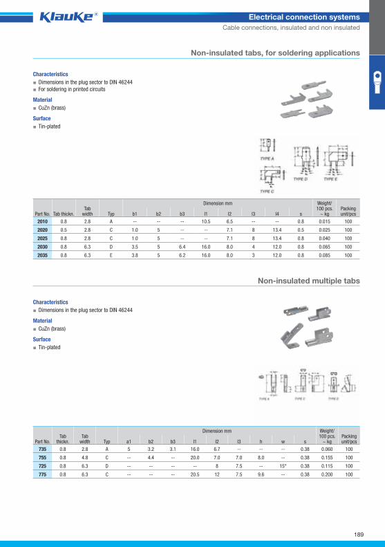
2010grp
735grp
189
Electrical connection systems
Cable connections, insulated and non insulated
Part No. Tab thickn. Tab
width Typ
Dimension mm Weight/100 pcs.
~ kg Packing unit/pcs b1 b2 b3 l1 l2 l3 l4 s
2010 0.8 2.8 A -- -- -- 10.5 6.5 -- -- 0.8 0.015 100
2020 0.5 2.8 C 1.0 5 -- -- 7.1 8 13.4 0.5 0.025 100
2025 0.8 2.8 C 1.0 5 -- -- 7.1 8 13.4 0.8 0.040 100
2030 0.8 6.3 D 3.5 5 6.4 16.0 8.0 4 12.0 0.8 0.065 100
2035 0.8 6.3 E 3.8 5 6.2 16.0 8.0 3 12.0 0.8 0.085 100
Part No. Tab
thickn. Tab
width Typ
Dimension mm Weight/100 pcs.
~ kg Packing unit/pcs a1 b2 b3 l1 l2 l3 h w s
735 0.8 2.8 A 5 3.2 3.1 16.0 6.7 -- -- -- 0.38 0.060 100
755 0.8 4.8 C -- 4.4 -- 20.0 7.0 7.0 8.0 -- 0.38 0.155 100
725 0.8 6.3 D -- -- -- -- 8 7.5 -- 15° 0.38 0.115 100
775 0.8 6.3 C -- -- -- 20.5 12 7.5 9.6 -- 0.38 0.200 100
Non-insulated tabs, for soldering applications
Characteristics
▪ Dimensions in the plug sector to DIN 46244
▪ For soldering in printed circuits
Material
▪ CuZn (brass)
Surface
▪ Tin-plated
Non-insulated multiple tabs
Characteristics
▪ Dimensions in the plug sector to DIN 46244
Material
▪ CuZn (brass)
Surface
▪ Tin-plated
Klauke Hauptkatalog EN_DIN A5.indb 189 07.10.2014 12:17:33
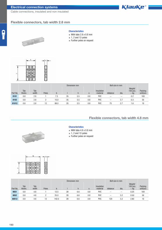
8101grp
8051grp
190
Electrical connection systems
Cable connections, insulated and non insulated
Dimension mm Bolt size in mm
Part No. Tab
thickn. Tab
width Poles b l h s Insulation material distance dia.
Weight/100 pcs.
~ kg Packing unit/pcs
8101 0.8 2.8 1 7.5 35 5.5 0.8 PVC -- -- 0.2 100
8102 0.8 2.8 2 15.0 35 5.5 0.8 PVC -- 2.7 0.3 50
81012 0.8 2.8 12 88.0 35 5.5 0.8 PVC 75 2.7 1.6 10
Dimension mm Bolt size in mm
Part No. Tab
thickn. Tab
width Poles b l h s Insulation material distance dia.
Weight/100 pcs.
~ kg Packing unit/pcs
8051 0.8 4.8 1 12.5 28 6.6 0.8 PVC -- -- 0.25 100
8052 0.8 4.8 2 25.0 28 6.6 0.8 PVC -- 3.2 0.50 50
80512 0.8 4.8 12 142.0 28 6.6 0.8 PVC 120 3.2 2.80 10
Flexible connectors, tab width 2.8 mm
Characteristics
▪ With tabs 2.8 x 0.8 mm
▪ 1, 2 and 12-poles
▪ Further poles on request
Flexible connectors, tab width 4.8 mm
Characteristics
▪ With tabs 4.8 x 0.8 mm
▪ 1, 2 and 12-poles
▪ Further poles on request
Klauke Hauptkatalog EN_DIN A5.indb 190 07.10.2014 12:17:33
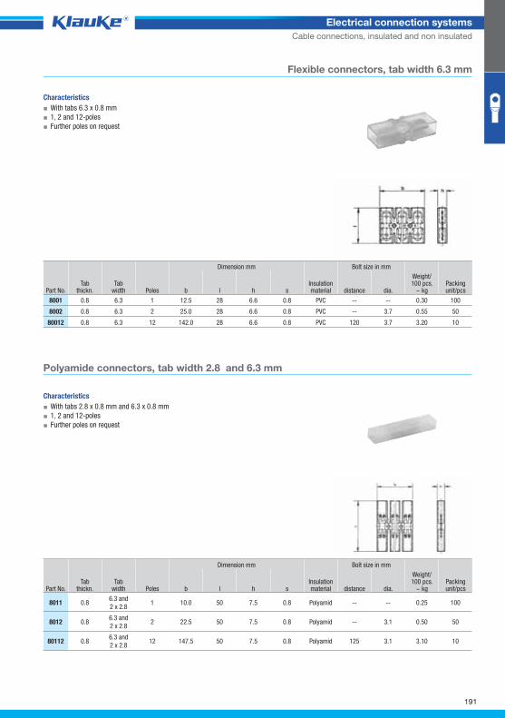
8001grp
8011grp
191
Electrical connection systems
Cable connections, insulated and non insulated
Dimension mm Bolt size in mm
Part No. Tab
thickn. Tab
width Poles b l h s Insulation material distance dia.
Weight/100 pcs.
~ kg Packing unit/pcs
8001 0.8 6.3 1 12.5 28 6.6 0.8 PVC -- -- 0.30 100
8002 0.8 6.3 2 25.0 28 6.6 0.8 PVC -- 3.7 0.55 50
80012 0.8 6.3 12 142.0 28 6.6 0.8 PVC 120 3.7 3.20 10
Dimension mm Bolt size in mm
Part No. Tab
thickn. Tab
width Poles b l h s Insulation material distance dia.
Weight/100 pcs.
~ kg Packing unit/pcs
8011 0.8 6.3 and
2 x 2.8 1 10.0 50 7.5 0.8 Polyamid -- -- 0.25 100
8012 0.8 6.3 and
2 x 2.8 2 22.5 50 7.5 0.8 Polyamid -- 3.1 0.50 50
80112 0.8 6.3 and
2 x 2.8 12 147.5 50 7.5 0.8 Polyamid 125 3.1 3.10 10
Flexible connectors, tab width 6.3 mm
Characteristics
▪ With tabs 6.3 x 0.8 mm
▪ 1, 2 and 12-poles
▪ Further poles on request
Polyamide connectors, tab width 2.8 and 6.3 mm
Characteristics
▪ With tabs 2.8 x 0.8 mm and 6.3 x 0.8 mm
▪ 1, 2 and 12-poles
▪ Further poles on request
Klauke Hauptkatalog EN_DIN A5.indb 191 07.10.2014 12:17:34
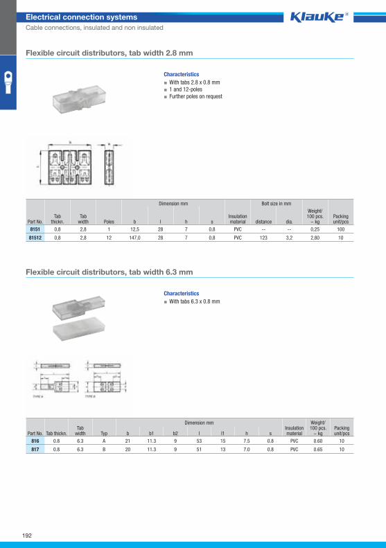
8151grp
816grp
192
Electrical connection systems
Cable connections, insulated and non insulated
Dimension mm Bolt size in mm
Part No. Tab
thickn. Tab
width Poles b l h s Insulation material distance dia.
Weight/100 pcs.
~ kg Packing unit/pcs
8151 0,8 2,8 1 12,5 28 7 0,8 PVC -- -- 0,25 100
81512 0,8 2,8 12 147,0 28 7 0,8 PVC 123 3,2 2,80 10
Flexible circuit distributors, tab width 2.8 mm
Characteristics
▪ With tabs 2.8 x 0.8 mm
▪ 1 and 12-poles
▪ Further poles on request
Flexible circuit distributors, tab width 6.3 mm
Characteristics
▪ With tabs 6.3 x 0.8 mm
Part No. Tab thickn. Tab
width Typ
Dimension mm Insulation material
Weight/100 pcs.
~ kg Packing unit/pcs b b1 b2 l l1 h s
816 0.8 6.3 A 21 11.3 9 53 15 7.5 0.8 PVC 0.60 10
817 0.8 6.3 B 20 11.3 9 51 13 7.0 0.8 PVC 0.65 10
Klauke Hauptkatalog EN_DIN A5.indb 192 07.10.2014 12:17:34
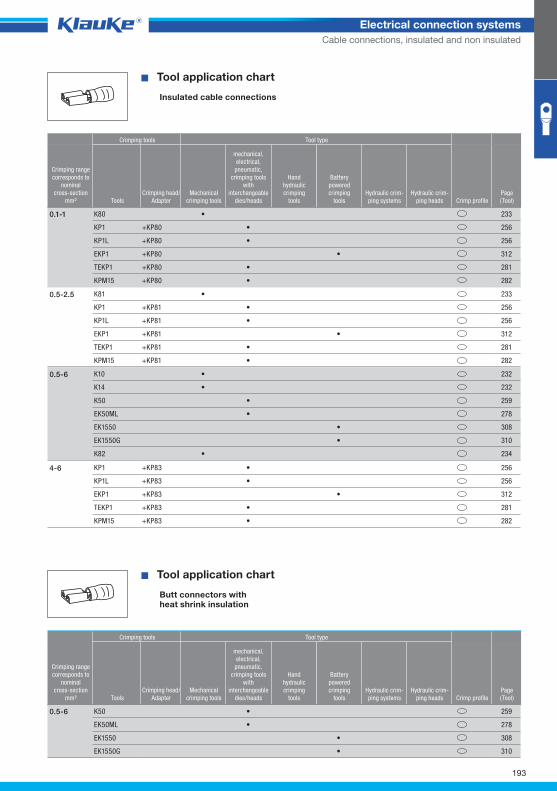
^WZT_KV_isoliert^
^WZT_SV_isoliert^
193
Electrical connection systems
Cable connections, insulated and non insulated
� Tool application chart
Insulated cable connections
Crimping tools Tool type
Crimping rangecorresponds to
nominalcross-section
mm² ToolsCrimping head/
AdapterMechanical
crimping tools
mechanical,electrical,
pneumatic, crimping tools
with interchangeable
dies/heads
Handhydraulic crimping
tools
Batterypowered crimping
toolsHydraulic crim-ping systems
Hydraulic crim-ping heads Crimp profile
Page(Tool)
K80 • 233
KP1 +KP80 • 256
KP1L +KP80 • 256
EKP1 +KP80 • 312
TEKP1 +KP80 • 281
KPM15 +KP80 • 282
0.1-1
K81 • 233
KP1 +KP81 • 256
KP1L +KP81 • 256
EKP1 +KP81 • 312
TEKP1 +KP81 • 281
KPM15 +KP81 • 282
0.5-2.5
K10 • 232
K14 • 232
K50 • 259
EK50ML • 278
EK1550 • 308
EK1550G • 310
K82 • 234
0.5-6
KP1 +KP83 • 256
KP1L +KP83 • 256
EKP1 +KP83 • 312
TEKP1 +KP83 • 281
KPM15 +KP83 • 282
4-6
� Tool application chart
Butt connectors withheat shrink insulation
Crimping tools Tool type
Crimping rangecorresponds to
nominalcross-section
mm² ToolsCrimping head/
AdapterMechanical
crimping tools
mechanical,electrical,
pneumatic, crimping tools
with interchangeable
dies/heads
Handhydraulic crimping
tools
Batterypowered crimping
toolsHydraulic crim-ping systems
Hydraulic crim-ping heads Crimp profile
Page(Tool)
K50 • 259
EK50ML • 278
EK1550 • 308
EK1550G • 310
0.5-6
Klauke Hauptkatalog EN_DIN A5.indb 193 07.10.2014 12:17:35
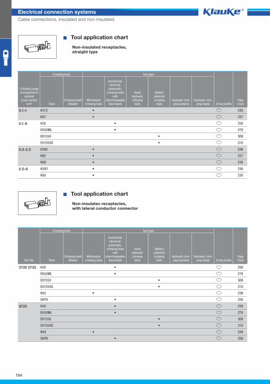
^WZT_FSH_gerade^
^WZT_FSH_seitlich^
194
Electrical connection systems
Cable connections, insulated and non insulated
� Tool application chart
Non-insulated receptacles,straight type
Crimping tools Tool type
Crimping rangecorresponds to
nominalcross-section
mm² ToolsCrimping head/
AdapterMechanical
crimping tools
mechanical,electrical,
pneumatic, crimping tools
with interchangeable
dies/heads
Handhydraulic crimping
tools
Batterypowered crimping
toolsHydraulic crim-ping systems
Hydraulic crim-ping heads Crimp profile
Page(Tool)
K572 • 235
K67 • 237
0.1-1
K50 • 259
EK50ML • 278
EK1550 • 308
EK1550G • 310
0.1-6
K582 • 236
K65 • 237
K68 • 239
0.5-2.5
K592 • 236
K60 • 235
0.5-6
� Tool application chart
Non-insulatec receptacles,with lateral conductor connector
Crimping tools Tool type
Part No. ToolsCrimping head/
AdapterMechanical
crimping tools
mechanical,electrical,
pneumatic, crimping tools
with interchangeable
dies/heads
Handhydraulic crimping
tools
Batterypowered crimping
toolsHydraulic crim-ping systems
Hydraulic crim-ping heads Crimp profile
Page(Tool)
K50 • 259
EK50ML • 278
EK1550 • 308
EK1550G • 310
K63 • 238
SKP6 • 258
3720 3735
K50 • 259
EK50ML • 278
EK1550 • 308
EK1550G • 310
K64 • 238
SKP6 • 258
3725
Klauke Hauptkatalog EN_DIN A5.indb 194 07.10.2014 12:17:35
195
Electrical connection systems
Cable connections, insulated and non insulated
Klauke Hauptkatalog EN_DIN A5.indb 195 07.10.2014 12:17:35
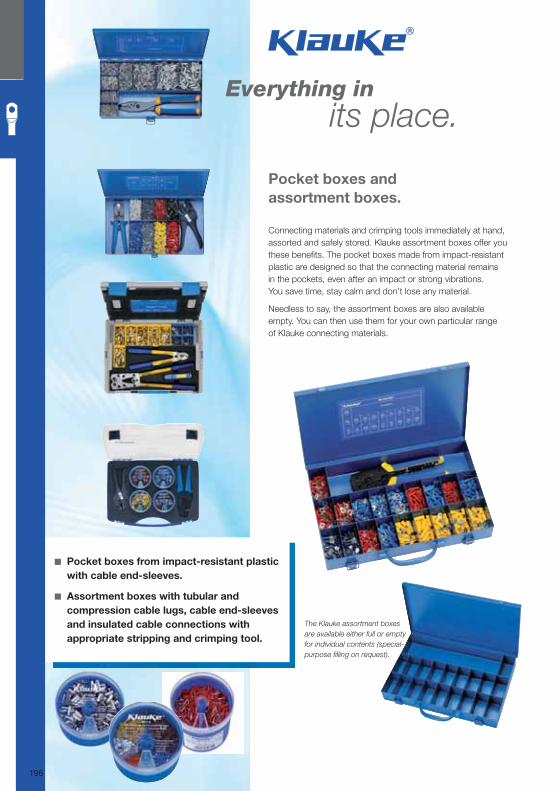
Pocket boxes and
assortment boxes.
Connecting materials and crimping tools immediately at hand, assorted and safely stored. Klauke assortment boxes offer you these benefi ts. The pocket boxes made from impact-resistant plastic are designed so that the connecting material remains in the pockets, even after an impact or strong vibrations. You save time, stay calm and don’t lose any material.
Needless to say, the assortment boxes are also available empty. You can then use them for your own particular range of Klauke connecting materials.
Everything in its place.
◾ Pocket boxes from impact-resistant plastic
with cable end-sleeves.
◾ Assortment boxes with tubular and
compression cable lugs, cable end-sleeves
and insulated cable connections with
appropriate stripping and crimping tool.
The Klauke assortment boxes
are available either full or empty
for individual contents (special-
purpose fi lling on request).
196
Klauke Hauptkatalog EN_DIN A5.indb 196 07.10.2014 12:17:36
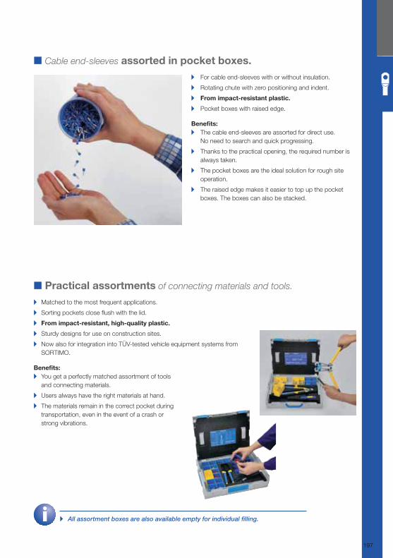
▸ All assortment boxes are also available empty for individual fi lling.
■ Cable end-sleeves assorted in pocket boxes.
▸ For cable end-sleeves with or without insulation.
▸ Rotating chute with zero positioning and indent.
▸ From impact-resistant plastic.
▸ Pocket boxes with raised edge.
Benefi ts: ▸ The cable end-sleeves are assorted for direct use.
No need to search and quick progressing.
▸ Thanks to the practical opening, the required number is
always taken.
▸ The pocket boxes are the ideal solution for rough site
operation.
▸ The raised edge makes it easier to top up the pocket
boxes. The boxes can also be stacked.
■ Practical assortments of connecting materials and tools.
▸ Matched to the most frequent applications.
▸ Sorting pockets close fl ush with the lid.
▸ From impact-resistant, high-quality plastic.
▸ Sturdy designs for use on construction sites.
▸ Now also for integration into TÜV-tested vehicle equipment systems from
SORTIMO.
Benefi ts: ▸ You get a perfectly matched assortment of tools
and connecting materials.
▸ Users always have the right materials at hand.
▸ The materials remain in the correct pocket during
transportation, even in the event of a crash or
strong vibrations.
197
Klauke Hauptkatalog EN_DIN A5.indb 197 07.10.2014 12:17:38
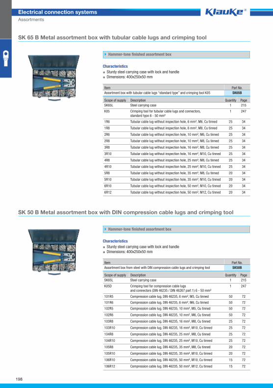
SK65Bgrp
SK50Bgrp
198
Electrical connection systems
Assortments
SK 65 B Metal assortment box with tubular cable lugs and crimping tool
Hammer-tone finished assortment box
Characteristics
▪ Sturdy steel carrying case with lock and handle
▪ Dimensions: 400x250x50 mm
Item Part No.
Assortment box with tubular cable lugs “standard type” and crimping tool K05 SK65B
Scope of supply Description Quantity Page
SK65L Steel carrying case 1 215
K05 Crimping tool for tubular cable lugs and connectors,
standard type 6 - 50 mm²
1 247
1R6 Tubular cable lug without inspection hole, 6 mm², M6, Cu tinned 25 34
1R8 Tubular cable lug without inspection hole, 6 mm², M8, Cu tinned 25 34
2R6 Tubular cable lug without inspection hole, 10 mm², M6, Cu tinned 25 34
2R8 Tubular cable lug without inspection hole, 10 mm², M8, Cu tinned 25 34
3R8 Tubular cable lug without inspection hole, 16 mm², M8, Cu tinned 25 34
3R10 Tubular cable lug without inspection hole, 16 mm², M10, Cu tinned 25 34
4R8 Tubular cable lug without inspection hole, 25 mm², M8, Cu tinned 25 34
4R10 Tubular cable lug without inspection hole, 25 mm², M10, Cu tinned 25 34
5R8 Tubular cable lug without inspection hole, 35 mm², M8, Cu tinned 20 34
5R10 Tubular cable lug without inspection hole, 35 mm², M10, Cu tinned 20 34
6R10 Tubular cable lug without inspection hole, 50 mm², M10, Cu tinned 20 34
6R12 Tubular cable lug without inspection hole, 50 mm², M12, Cu tinned 20 34
SK 50 B Metal assortment box with DIN compression cable lugs and crimping tool
Hammer-tone finished assortment box
Characteristics
▪ Sturdy steel carrying case with lock and handle
▪ Dimensions: 400x250x50 mm
Item Part No.
Assortment box from steel with DIN compression cable lugs and crimping tool SK50B
Scope of supply Description Quantity Page
SK65L Steel carrying case 1 215
K05D Crimping tool for compression cable lugs
and connectors (DIN 46235 / DIN 46267 part 1) 6 - 50 mm²
1 247
101R5 Compression cable lug, DIN 46235, 6 mm², M5, Cu tinned 50 72
101R6 Compression cable lug, DIN 46235, 6 mm², M6, Cu tinned 50 72
102R5 Compression cable lug, DIN 46235, 10 mm², M5, Cu tinned 50 72
102R6 Compression cable lug, DIN 46235, 10 mm², M6, Cu tinned 50 72
103R8 Compression cable lug, DIN 46235, 16 mm², M8, Cu tinned 25 72
103R10 Compression cable lug, DIN 46235, 16 mm², M10, Cu tinned 25 72
104R8 Compression cable lug, DIN 46235, 25 mm², M8, Cu tinned 25 72
104R10 Compression cable lug, DIN 46235, 25 mm², M10, Cu tinned 25 72
105R8 Compression cable lug, DIN 46235, 35 mm², M8, Cu tinned 20 72
105R10 Compression cable lug, DIN 46235, 35 mm², M10, Cu tinned 20 72
106R10 Compression cable lug, DIN 46235, 50 mm², M10, Cu tinned 15 72
106R12 Compression cable lug, DIN 46235, 50 mm², M12, Cu tinned 15 72
Klauke Hauptkatalog EN_DIN A5.indb 198 07.10.2014 12:17:38
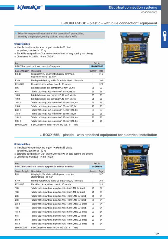
LBOXX65BCBgrp
LBOXX65Bgrp
199
Electrical connection systems
Assortments
L-BOXX 65BCB - plastic - with blue connection® equipment
Extensive equipment based on the blue connection® product line,
including crimping tool, cutting tool and electrician‘s knife
Characteristics
▪ Manufactured from shock and impact resistant ABS plastic,
very robust, loadable to 100 kg
▪ Stackable using an Easy-Click system which allows an easy opening and closing
▪ Dimensions: 442x357x117 mm (W/D/H)
Item Part No.
L-BOXX from plastic with blue connection® equipment LBOXX65BCB
Scope of supply Description Quantity Page
K05BC Crimping tool for tubular cable lugs and connectors,
blue connection® 6 - 50 mm²
1 246
K100 Hand-operated cutting tool for Cu and Al cables to 14 mm dia. 1 268
KL740416 Electrician‘s knife, without blade 4 - 16 mm dia. 1 520
6B6 Rohrkabelschuhe, blue connection®, 6 mm², M6, Cu 25 26
6B8 Tubular cable lugs, blue connection®, 6 mm², M8, Cu 25 26
10B6 Rohrkabelschuhe, blue connection®, 10 mm², M6, Cu 25 26
10B8 Rohrkabelschuhe, blue connection®, 10 mm², M8, Cu 25 26
16B10 Tubular cable lugs, blue connection®, 16 mm², M10, Cu 25 26
25B8 Tubular cable lugs, blue connection®, 25 mm², M8, Cu 20 26
25B10 Tubular cable lugs, blue connection®, 25 mm², M10, Cu 20 26
35B8 Tubular cable lugs, blue connection®, 35 mm², M8, Cu 20 26
35B10 Tubular cable lugs, blue connection®, 35 mm², M10, Cu 20 26
50B10 Tubular cable lugs, blue connection®, 50 mm², M10, Cu 20 26
LBOXX102LFG L-BOXX with front handle (W/D/H: 442 x 357 x 117 mm) 1
L-BOXX 65B - plastic - with standard equipment for electrical installation
Characteristics
▪ Manufactured from shock and impact resistant ABS plastic,
very robust, loadable to 100 kg
▪ Stackable using an Easy-Click system which allows an easy opening and closing
▪ Dimensions: 442x357x117 mm (W/D/H)
Item Part No.
L-BOXX from plastic with standard equipment for electrical installation LBOXX65B
Scope of supply Description Quantity Page
K05 Crimping tool for tubular cable lugs and connectors,
standard type 6 - 50 mm²
1 247
K100 Hand-operated cutting tool for Cu and Al cables to 14 mm dia. 1 268
KL740416 Electrician‘s knife, without blade 4 - 16 mm dia. 1 520
1R6 Tubular cable lug without inspection hole, 6 mm², M6, Cu tinned 25 34
1R8 Tubular cable lug without inspection hole, 6 mm², M8, Cu tinned 25 34
2R6 Tubular cable lug without inspection hole, 10 mm², M6, Cu tinned 25 34
2R8 Tubular cable lug without inspection hole, 10 mm², M8, Cu tinned 25 34
3R10 Tubular cable lug without inspection hole, 16 mm², M10, Cu tinned 25 34
4R8 Tubular cable lug without inspection hole, 25 mm², M8, Cu tinned 20 34
4R10 Tubular cable lug without inspection hole, 25 mm², M10, Cu tinned 20 34
5R8 Tubular cable lug without inspection hole, 35 mm², M8, Cu tinned 20 34
5R10 Tubular cable lug without inspection hole, 35 mm², M10, Cu tinned 20 34
6R10 Tubular cable lug without inspection hole, 50 mm², M10, Cu tinned 15 34
LBOXX102LFG L-BOXX with front handle (W/D/H: 442 x 357 x 117 mm) 1
Klauke Hauptkatalog EN_DIN A5.indb 199 07.10.2014 12:17:39
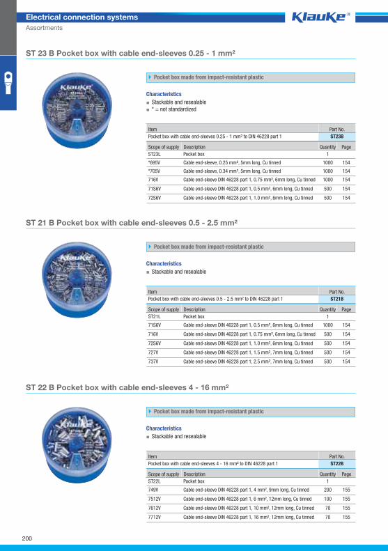
ST23Bgrp
ST21Bgrp
ST22Bgrp
200
Electrical connection systems
Assortments
ST 23 B Pocket box with cable end-sleeves 0.25 - 1 mm²
Pocket box made from impact-resistant plastic
Characteristics
▪ Stackable and resealable
▪ * = not standardized
Item Part No.
Pocket box with cable end-sleeves 0.25 - 1 mm² to DIN 46228 part 1 ST23B
Scope of supply Description Quantity Page
ST23L Pocket box 1
*695V Cable end-sleeve, 0.25 mm², 5mm long, Cu tinned 1000 154
*705V Cable end-sleeve, 0.34 mm², 5mm long, Cu tinned 1000 154
716V Cable end-sleeve DIN 46228 part 1, 0.75 mm², 6mm long, Cu tinned 1000 154
71S6V Cable end-sleeve DIN 46228 part 1, 0.5 mm², 6mm long, Cu tinned 500 154
72S6V Cable end-sleeve DIN 46228 part 1, 1.0 mm², 6mm long, Cu tinned 500 154
ST 21 B Pocket box with cable end-sleeves 0.5 - 2.5 mm²
Pocket box made from impact-resistant plastic
Characteristics
▪ Stackable and resealable
Item Part No.
Pocket box with cable end-sleeves 0.5 - 2.5 mm² to DIN 46228 part 1 ST21B
Scope of supply Description Quantity Page
ST21L Pocket box 1
71S6V Cable end-sleeve DIN 46228 part 1, 0.5 mm², 6mm long, Cu tinned 1000 154
716V Cable end-sleeve DIN 46228 part 1, 0.75 mm², 6mm long, Cu tinned 500 154
72S6V Cable end-sleeve DIN 46228 part 1, 1.0 mm², 6mm long, Cu tinned 500 154
727V Cable end-sleeve DIN 46228 part 1, 1.5 mm², 7mm long, Cu tinned 500 154
737V Cable end-sleeve DIN 46228 part 1, 2.5 mm², 7mm long, Cu tinned 500 154
ST 22 B Pocket box with cable end-sleeves 4 - 16 mm²
Pocket box made from impact-resistant plastic
Characteristics
▪ Stackable and resealable
Item Part No.
Pocket box with cable end-sleeves 4 - 16 mm² to DIN 46228 part 1 ST22B
Scope of supply Description Quantity Page
ST22L Pocket box 1
749V Cable end-sleeve DIN 46228 part 1, 4 mm², 9mm long, Cu tinned 200 155
7512V Cable end-sleeve DIN 46228 part 1, 6 mm², 12mm long, Cu tinned 100 155
7612V Cable end-sleeve DIN 46228 part 1, 10 mm², 12mm long, Cu tinned 70 155
7712V Cable end-sleeve DIN 46228 part 1, 16 mm², 12mm long, Cu tinned 70 155
Klauke Hauptkatalog EN_DIN A5.indb 200 07.10.2014 12:17:39
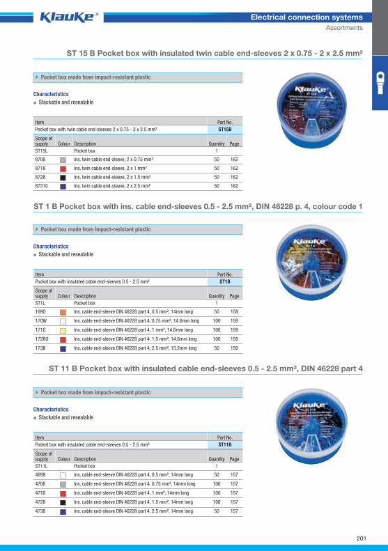
ST15Bgrp
ST1Bgrp
ST11Bgrp
201
Electrical connection systems
Assortments
ST 15 B Pocket box with insulated twin cable end-sleeves 2 x 0.75 - 2 x 2.5 mm²
Pocket box made from impact-resistant plastic
Characteristics
▪ Stackable and resealable
Item Part No.
Pocket box with twin cable end-sleeves 2 x 0.75 - 2 x 2.5 mm² ST15B
Scope of supply Colour Description Quantity Page
ST15L Pocket box 1
8708 Ins. twin cable end-sleeve, 2 x 0.75 mm² 50 162
8718 Ins. twin cable end-sleeve, 2 x 1 mm² 50 162
8728 Ins. twin cable end-sleeve, 2 x 1.5 mm² 50 162
87310 Ins. twin cable end-sleeve, 2 x 2.5 mm² 50 162
ST 1 B Pocket box with ins. cable end-sleeves 0.5 - 2.5 mm², DIN 46228 p. 4, colour code 1
Pocket box made from impact-resistant plastic
Characteristics
▪ Stackable and resealable
Item Part No.
Pocket box with insulated cable end-sleeves 0.5 - 2.5 mm² ST1B
Scope of supply Colour Description Quantity Page
ST1L Pocket box 1
169O Ins. cable end-sleeve DIN 46228 part 4, 0.5 mm², 14mm long 50 158
170W Ins. cable end-sleeve DIN 46228 part 4, 0.75 mm², 14.6mm long 100 159
171G Ins. cable end-sleeve DIN 46228 part 4, 1 mm², 14.6mm long 100 159
172RO Ins. cable end-sleeve DIN 46228 part 4, 1.5 mm², 14.6mm long 100 159
173B Ins. cable end-sleeve DIN 46228 part 4, 2.5 mm², 15.2mm long 50 159
ST 11 B Pocket box with insulated cable end-sleeves 0.5 - 2.5 mm², DIN 46228 part 4
Pocket box made from impact-resistant plastic
Characteristics
▪ Stackable and resealable
Item Part No.
Pocket box with insulated cable end-sleeves 0.5 - 2.5 mm² ST11B
Scope of supply Colour Description Quantity Page
ST11L Pocket box 1
4698 Ins. cable end-sleeve DIN 46228 part 4, 0.5 mm², 14mm long 50 157
4708 Ins. cable end-sleeve DIN 46228 part 4, 0.75 mm², 14mm long 100 157
4718 Ins. cable end-sleeve DIN 46228 part 4, 1 mm², 14mm long 100 157
4728 Ins. cable end-sleeve DIN 46228 part 4, 1.5 mm², 14mm long 100 157
4738 Ins. cable end-sleeve DIN 46228 part 4, 2.5 mm², 14mm long 50 157
Klauke Hauptkatalog EN_DIN A5.indb 201 07.10.2014 12:17:39
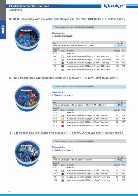
ST31Bgrp
ST12Bgrp
ST2Bgrp
202
Electrical connection systems
Assortments
ST 31 B Pocket box with ins. cable end-sleeves 0.5 - 2.5 mm², DIN 46228 p. 4, colour code 2
Pocket box made from impact-resistant plastic
Characteristics
▪ Stackable and resealable
Item Part No.
Pocket box with insulated cable end-sleeves 0.5 - 2.5 mm² ST31B
Scope of supply Colour Description Quantity Page
ST31L Pocket box 1
1698 Ins. cable end-sleeve DIN 46228 part 4, 0.5 mm², 13mm long 50 160
1708 Ins. cable end-sleeve DIN 46228 part 4, 0.75 mm², 13.5mm long 100 160
1718 Ins. cable end-sleeve DIN 46228 part 4, 1 mm², 13.5mm long 100 160
1728 Ins. cable end-sleeve DIN 46228 part 4, 1.5 mm², 13.5mm long 100 160
1738 Ins. cable end-sleeve DIN 46228 part 4, 2.5 mm², 14.5mm long 50 160
ST 12 B Pocket box with insulated cable end-sleeves 4 - 16 mm², DIN 46228 part 4
Pocket box made from impact-resistant plastic
Characteristics
▪ Stackable and resealable
Item Part No.
Pocket box with insulated cable end-sleeves 4 - 16 mm² to DIN 46228 part 4 ST12B
Scope of supply Colour Description Quantity Page
ST12L Pocket box 1
47410 Ins. cable end-sleeve DIN 46228 part 4, 4 mm², 17mm long 50 157
47512 Ins. cable end-sleeve DIN 46228 part 4, 6 mm², 20mm long 20 157
47612 Ins. cable end-sleeve DIN 46228 part 4, 10 mm², 22mm long 20 157
47712 Ins. cable end-sleeve DIN 46228 part 4, 16 mm², 24mm long 10 157
ST 2 B Pocket box with cable end-sleeves 4 - 16 mm², DIN 46228 part 4, colour code 1
Pocket box made from impact-resistant plastic
Characteristics
▪ Stackable and resealable
Item Part No.
Pocket box with insulated cable end-sleeves 4 - 16 mm² ST2B
Scope of supply Colour Description Quantity Page
ST2L Pocket box 1
174GR Ins. cable end-sleeve DIN 46228 part 4, 4 mm², 16.5mm long 50 159
175S Ins. cable end-sleeve DIN 46228 part 4, 6 mm², 20mm long 20 159
176E Ins. cable end-sleeve DIN 46228 part 4, 10 mm², 21.5mm long 20 159
177GR Ins. cable end-sleeve DIN 46228 part 4, 16 mm², 22.2mm long 10 159
Klauke Hauptkatalog EN_DIN A5.indb 202 07.10.2014 12:17:39
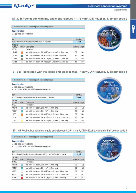
ST32Bgrp
ST3Bgrp
ST13Bgrp
203
Electrical connection systems
Assortments
ST 32 B Pocket box with ins. cable end-sleeves 4 - 16 mm², DIN 46228 p. 4, colour code 2
Pocket box made from impact-resistant plastic
Characteristics
▪ Stackable and resealable
Item Part No.
Pocket box with insulated cable end-sleeves 4 - 16 mm² ST32B
Scope of supply Colour Description Quantity Page
ST32L Pocket box 1
17410 Ins. cable end-sleeve DIN 46228 part 4, 4 mm², 16.5mm long 50 160
17512 Ins. cable end-sleeve DIN 46228 part 4, 6 mm², 20mm long 20 160
17612 Ins. cable end-sleeve DIN 46228 part 4, 10 mm², 21.5mm long 20 160
17712 Ins. cable end-sleeve DIN 46228 part 4, 16 mm², 23.5mm long 10 160
ST 3 B Pocket box with ins. cable end-sleeves 0.25 - 1 mm², DIN 46228 p. 4, colour code 1
Pocket box made from impact-resistant plastic
Characteristics
▪ Stackable and resealable
▪ * = Part No. 167H and 168T are not standardized
Item Part No.
Pocket box with insulated twin cable end-sleeves 0.25-1 mm² ST3B
Scope of supply Colour Description Quantity Page
ST3L Pocket box 1
*167H Ins. cable end-sleeve, 0.25 mm², 10.4mm long 30 158
*168T Ins. cable end-sleeve, 0.34 mm², 10.4mm long 30 158
169O Ins. cable end-sleeve DIN 46228 part 4, 0.5 mm², 14mm long 30 158
170W Ins. cable end-sleeve DIN 46228 part 4, 0.75 mm², 14.6mm long 30 159
171G Ins. cable end-sleeve DIN 46228 part 4, 1 mm², 14.6mm long 30 159
ST 13 B Pocket box with ins. cable end-sleeves 0.25 - 1 mm², DIN 46228 p. 4 and similar, colour code 1
Pocket box made from impact-resistant plastic
Characteristics
▪ Stackable and resealable
▪ * = Part No. 167H and 168T are not standardized
Item Part No.
Pocket box with insulated cable end-sleeves 0.25 - 1 mm² to DIN 46228 part 4 ST13B
Scope of supply Colour Description Quantity Page
ST13L Pocket box 1
*167H Ins. cable end-sleeve, 0.25 mm², 10.4mm long 30 158
*168T Ins. cable end-sleeve, 0.34 mm², 10.4mm long 30 158
4698 Ins. cable end-sleeve DIN 46228 part 4, 0.5 mm², 14mm long 30 157
4708 Ins. cable end-sleeve DIN 46228 part 4, 0.75 mm², 14mm long 30 157
4718 Ins. cable end-sleeve DIN 46228 part 4, 1 mm², 14mm long 30 157
Klauke Hauptkatalog EN_DIN A5.indb 203 07.10.2014 12:17:40
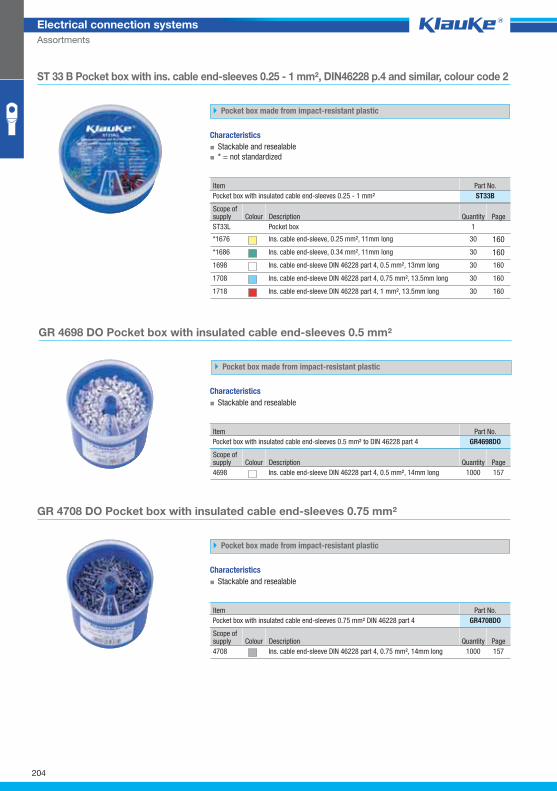
ST33Bgrp
GR4698DOgrp
GR4708DOgrp
204
Electrical connection systems
Assortments
ST 33 B Pocket box with ins. cable end-sleeves 0.25 - 1 mm², DIN46228 p.4 and similar, colour code 2
Pocket box made from impact-resistant plastic
Characteristics
▪ Stackable and resealable
▪ * = not standardized
Item Part No.
Pocket box with insulated cable end-sleeves 0.25 - 1 mm² ST33B
Scope of supply Colour Description Quantity Page
ST33L Pocket box 1
*1676 Ins. cable end-sleeve, 0.25 mm², 11mm long 30 160
*1686 Ins. cable end-sleeve, 0.34 mm², 11mm long 30 160
1698 Ins. cable end-sleeve DIN 46228 part 4, 0.5 mm², 13mm long 30 160
1708 Ins. cable end-sleeve DIN 46228 part 4, 0.75 mm², 13.5mm long 30 160
1718 Ins. cable end-sleeve DIN 46228 part 4, 1 mm², 13.5mm long 30 160
GR 4698 DO Pocket box with insulated cable end-sleeves 0.5 mm²
Pocket box made from impact-resistant plastic
Characteristics
▪ Stackable and resealable
Item Part No.
Pocket box with insulated cable end-sleeves 0.5 mm² to DIN 46228 part 4 GR4698DO
Scope of supply Colour Description Quantity Page
4698 Ins. cable end-sleeve DIN 46228 part 4, 0.5 mm², 14mm long 1000 157
GR 4708 DO Pocket box with insulated cable end-sleeves 0.75 mm²
Pocket box made from impact-resistant plastic
Characteristics
▪ Stackable and resealable
Item Part No.
Pocket box with insulated cable end-sleeves 0.75 mm² DIN 46228 part 4 GR4708DO
Scope of supply Colour Description Quantity Page
4708 Ins. cable end-sleeve DIN 46228 part 4, 0.75 mm², 14mm long 1000 157
Klauke Hauptkatalog EN_DIN A5.indb 204 07.10.2014 12:17:40
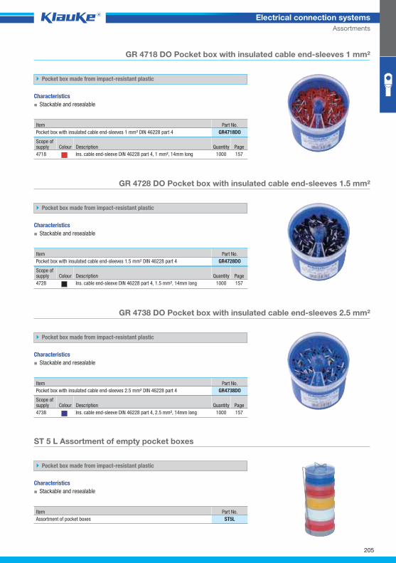
GR4718DOgrp
GR4728DOgrp
GR4738DOgrp
ST5Lgrp
205
Electrical connection systems
Assortments
GR 4718 DO Pocket box with insulated cable end-sleeves 1 mm²
Pocket box made from impact-resistant plastic
Characteristics
▪ Stackable and resealable
Item Part No.
Pocket box with insulated cable end-sleeves 1 mm² DIN 46228 part 4 GR4718DO
Scope of supply Colour Description Quantity Page
4718 Ins. cable end-sleeve DIN 46228 part 4, 1 mm², 14mm long 1000 157
GR 4728 DO Pocket box with insulated cable end-sleeves 1.5 mm²
Pocket box made from impact-resistant plastic
Characteristics
▪ Stackable and resealable
Item Part No.
Pocket box with insulated cable end-sleeves 1.5 mm² DIN 46228 part 4 GR4728DO
Scope of supply Colour Description Quantity Page
4728 Ins. cable end-sleeve DIN 46228 part 4, 1.5 mm², 14mm long 1000 157
GR 4738 DO Pocket box with insulated cable end-sleeves 2.5 mm²
Pocket box made from impact-resistant plastic
Characteristics
▪ Stackable and resealable
Item Part No.
Pocket box with insulated cable end-sleeves 2.5 mm² DIN 46228 part 4 GR4738DO
Scope of supply Colour Description Quantity Page
4738 Ins. cable end-sleeve DIN 46228 part 4, 2.5 mm², 14mm long 1000 157
ST 5 L Assortment of empty pocket boxes
Pocket box made from impact-resistant plastic
Characteristics
▪ Stackable and resealable
Item Part No.
Assortment of pocket boxes ST5L
Klauke Hauptkatalog EN_DIN A5.indb 205 07.10.2014 12:17:41
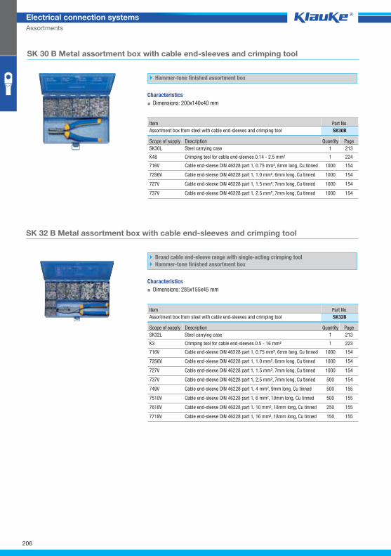
SK30Bgrp
SK32Bgrp
206
Electrical connection systems
Assortments
SK 30 B Metal assortment box with cable end-sleeves and crimping tool
Hammer-tone finished assortment box
Characteristics
▪ Dimensions: 200x140x40 mm
Item Part No.
Assortment box from steel with cable end-sleeves and crimping tool SK30B
Scope of supply Description Quantity Page
SK30L Steel carrying case 1 213
K48 Crimping tool for cable end-sleeves 0.14 - 2.5 mm² 1 224
716V Cable end-sleeve DIN 46228 part 1, 0.75 mm², 6mm long, Cu tinned 1000 154
72S6V Cable end-sleeve DIN 46228 part 1, 1.0 mm², 6mm long, Cu tinned 1000 154
727V Cable end-sleeve DIN 46228 part 1, 1.5 mm², 7mm long, Cu tinned 1000 154
737V Cable end-sleeve DIN 46228 part 1, 2.5 mm², 7mm long, Cu tinned 1000 154
SK 32 B Metal assortment box with cable end-sleeves and crimping tool
Broad cable end-sleeve range with single-acting crimping tool
Hammer-tone finished assortment box
Characteristics
▪ Dimensions: 285x155x45 mm
Item Part No.
Assortment box from steel with cable end-sleeves and crimping tool SK32B
Scope of supply Description Quantity Page
SK32L Steel carrying case 1 213
K3 Crimping tool for cable end-sleeves 0.5 - 16 mm² 1 223
716V Cable end-sleeve DIN 46228 part 1, 0.75 mm², 6mm long, Cu tinned 1000 154
72S6V Cable end-sleeve DIN 46228 part 1, 1.0 mm², 6mm long, Cu tinned 1000 154
727V Cable end-sleeve DIN 46228 part 1, 1.5 mm², 7mm long, Cu tinned 1000 154
737V Cable end-sleeve DIN 46228 part 1, 2.5 mm², 7mm long, Cu tinned 500 154
749V Cable end-sleeve DIN 46228 part 1, 4 mm², 9mm long, Cu tinned 500 155
7510V Cable end-sleeve DIN 46228 part 1, 6 mm², 10mm long, Cu tinned 500 155
7618V Cable end-sleeve DIN 46228 part 1, 10 mm², 18mm long, Cu tinned 250 155
7718V Cable end-sleeve DIN 46228 part 1, 16 mm², 18mm long, Cu tinned 150 155
Klauke Hauptkatalog EN_DIN A5.indb 206 07.10.2014 12:17:41
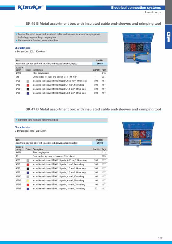
SK45Bgrp
SK47Bgrp
207
Electrical connection systems
Assortments
SK 45 B Metal assortment box with insulated cable end-sleeves and crimping tool
Four of the most important insulated cable end-sleeves in a steel carrying case
including single-acting crimping tool
Hammer-tone finished assortment box
Characteristics
▪ Dimensions: 200x140x40 mm
Item Part No.
Assortment box from steel with Ins. cable end-sleeves and crimping tool SK45B
Scope of supply Colour Description Quantity Page
SK30L Steel carrying case 1 213
K48 Crimping tool for cable end-sleeves 0.14 - 2.5 mm² 1 224
4708 Ins. cable end-sleeve DIN 46228 part 4, 0.75 mm², 14mm long 300 157
4718 Ins. cable end-sleeve DIN 46228 part 4, 1 mm², 14mm long 300 157
4728 Ins. cable end-sleeve DIN 46228 part 4, 1.5 mm², 14mm long 300 157
4738 Ins. cable end-sleeve DIN 46228 part 4, 2.5 mm², 14mm long 200 157
SK 47 B Metal assortment box with insulated cable end-sleeves and crimping tool
Hammer-tone finished assortment box
Characteristics
▪ Dimensions: 285x155x45 mm
Item Part No.
Assortment box from steel with Ins. cable end-sleeves and crimping tool SK47B
Scope of supply Colour Description Quantity Page
SK32L Steel carrying case 1 213
K3 Crimping tool for cable end-sleeves 0.5 - 16 mm² 1 223
4708 Ins. cable end-sleeve DIN 46228 part 4, 0.75 mm², 14mm long 200 157
4718 Ins. cable end-sleeve DIN 46228 part 4, 1 mm², 14mm long 200 157
4728 Ins. cable end-sleeve DIN 46228 part 4, 1.5 mm², 14mm long 200 157
4738 Ins. cable end-sleeve DIN 46228 part 4, 2.5 mm², 14mm long 200 157
47410 Ins. cable end-sleeve DIN 46228 part 4, 4 mm², 17mm long 100 157
47512 Ins. cable end-sleeve DIN 46228 part 4, 6 mm², 20mm long 100 157
47618 Ins. cable end-sleeve DIN 46228 part 4, 10 mm², 28mm long 100 157
47718 Ins. cable end-sleeve DIN 46228 part 4, 16 mm², 28mm long 50 157
Klauke Hauptkatalog EN_DIN A5.indb 207 07.10.2014 12:17:41
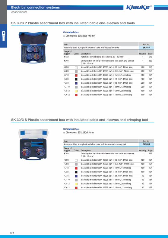
SK303Pgrp
SK303Sgrp
208
Electrical connection systems
Assortments
SK 30/3 P Plastic assortment box with insulated cable end-sleeves and tools
Characteristics
▪ Dimensions: 395x295x106 mm
Item Part No.
Assortment box from plastic with Ins. cable end-sleeves and tools SK303P
Scope of supply Colour Description Quantity Page
K432 Automatic wire stripping tool K43/2 0.02 - 10 mm² 1 516
K303 Crimping tool for cable end-sleeves and twin cable end-sleeves
0.08 - 10 mm²
1 229
4698 Ins. cable end-sleeve DIN 46228 part 4, 0.5 mm², 14mm long 400 157
4708 Ins. cable end-sleeve DIN 46228 part 4, 0.75 mm², 14mm long 400 157
4718 Ins. cable end-sleeve DIN 46228 part 4, 1 mm², 14mm long 400 157
4728 Ins. cable end-sleeve DIN 46228 part 4, 1.5 mm², 14mm long 400 157
4738 Ins. cable end-sleeve DIN 46228 part 4, 2.5 mm², 14mm long 200 157
47410 Ins. cable end-sleeve DIN 46228 part 4, 4 mm², 17mm long 200 157
47512 Ins. cable end-sleeve DIN 46228 part 4, 6 mm², 20mm long 100 157
47612 Ins. cable end-sleeve DIN 46228 part 4, 10 mm², 22mm long 100 157
SK 30/3 S Plastic assortment box with insulated cable end-sleeves and crimping tool
Characteristics
▪ Dimensions: 275x230x83 mm
Item Part No.
Assortment box from plastic with Ins. cable end-sleeves and crimping tool SK303S
Scope of supply Colour Description Quantity Page
K303 Crimping tool for cable end-sleeves and twin cable end-sleeves
0.08 - 10 mm²
1 229
4698 Ins. cable end-sleeve DIN 46228 part 4, 0.5 mm², 14mm long 100 157
4708 Ins. cable end-sleeve DIN 46228 part 4, 0.75 mm², 14mm long 100 157
4718 Ins. cable end-sleeve DIN 46228 part 4, 1 mm², 14mm long 100 157
4728 Ins. cable end-sleeve DIN 46228 part 4, 1.5 mm², 14mm long 100 157
4738 Ins. cable end-sleeve DIN 46228 part 4, 2.5 mm², 14mm long 50 157
47410 Ins. cable end-sleeve DIN 46228 part 4, 4 mm², 17mm long 50 157
47512 Ins. cable end-sleeve DIN 46228 part 4, 6 mm², 20mm long 30 157
47612 Ins. cable end-sleeve DIN 46228 part 4, 10 mm², 22mm long 30 157
Klauke Hauptkatalog EN_DIN A5.indb 208 07.10.2014 12:17:41
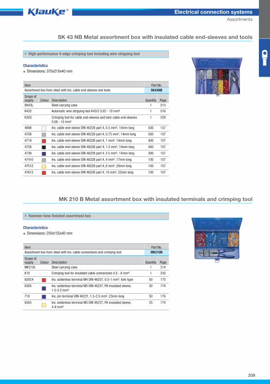
SK43NBgrp
209
Electrical connection systems
Assortments
SK 43 NB Metal assortment box with insulated cable end-sleeves and tools
High-performance 4-edge crimping tool including wire stripping tool
Characteristics
▪ Dimensions: 370x210x40 mm
Item Part No.
Assortment box from steel with Ins. cable end-sleeves and tools SK43NB
Scope of supply Colour Description Quantity Page
SK43L Steel carrying case 1 213
K432 Automatic wire stripping tool K43/2 0.02 - 10 mm² 1 516
K303 Crimping tool for cable end-sleeves and twin cable end-sleeves
0.08 - 10 mm²
1 229
4698 Ins. cable end-sleeve DIN 46228 part 4, 0.5 mm², 14mm long 500 157
4708 Ins. cable end-sleeve DIN 46228 part 4, 0.75 mm², 14mm long 500 157
4718 Ins. cable end-sleeve DIN 46228 part 4, 1 mm², 14mm long 400 157
4728 Ins. cable end-sleeve DIN 46228 part 4, 1.5 mm², 14mm long 400 157
4738 Ins. cable end-sleeve DIN 46228 part 4, 2.5 mm², 14mm long 300 157
47410 Ins. cable end-sleeve DIN 46228 part 4, 4 mm², 17mm long 100 157
47512 Ins. cable end-sleeve DIN 46228 part 4, 6 mm², 20mm long 100 157
47612 Ins. cable end-sleeve DIN 46228 part 4, 10 mm², 22mm long 100 157
MK 210 B Metal assortment box with insulated terminals and crimping tool
Hammer-tone finished assortment box
Characteristics
▪ Dimensions: 250x155x40 mm
Item Part No.
Assortment box from steel with Ins. cable connections and crimping tool MK210B
Scope of supply Colour Description Quantity Page
MK210L Steel carrying case 1 214
K10 Crimping tool for insulated cable connections 0.5 - 6 mm² 1 232
620C4 Ins. solderless terminal M4 DIN 46237, 0.5-1 mm², fork-type 50 175
6305 Ins. solderless terminal M5 DIN 46237, PA insulated sleeve,
1.5-2.5 mm²
50 174
710 Ins. pin terminal DIN 46231, 1.5-2.5 mm², 23mm long 50 176
6505 Ins. solderless terminal M5 DIN 46237, PA insulated sleeve,
4-6 mm²
25 174
Klauke Hauptkatalog EN_DIN A5.indb 209 07.10.2014 12:17:42
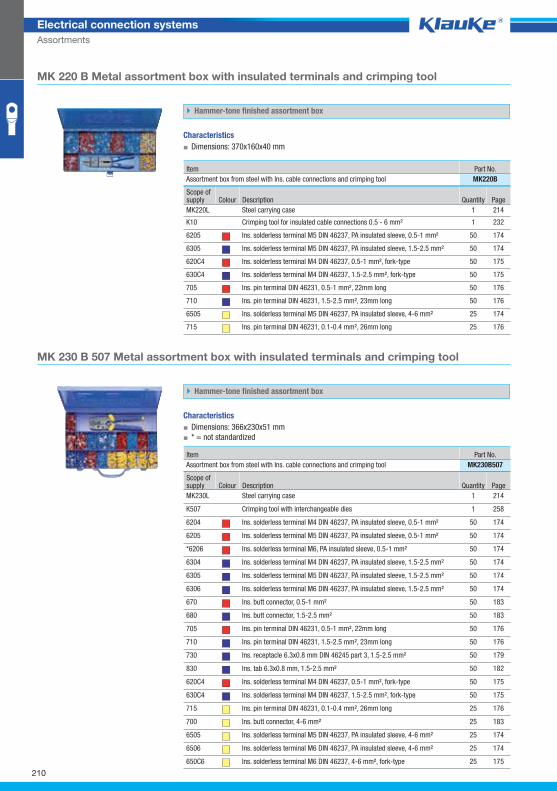
MK220Bgrp
MK230B507grp
210
Electrical connection systems
Assortments
MK 220 B Metal assortment box with insulated terminals and crimping tool
Hammer-tone finished assortment box
Characteristics
▪ Dimensions: 370x160x40 mm
Item Part No.
Assortment box from steel with Ins. cable connections and crimping tool MK220B
Scope of supply Colour Description Quantity Page
MK220L Steel carrying case 1 214
K10 Crimping tool for insulated cable connections 0.5 - 6 mm² 1 232
6205 Ins. solderless terminal M5 DIN 46237, PA insulated sleeve, 0.5-1 mm² 50 174
6305 Ins. solderless terminal M5 DIN 46237, PA insulated sleeve, 1.5-2.5 mm² 50 174
620C4 Ins. solderless terminal M4 DIN 46237, 0.5-1 mm², fork-type 50 175
630C4 Ins. solderless terminal M4 DIN 46237, 1.5-2.5 mm², fork-type 50 175
705 Ins. pin terminal DIN 46231, 0.5-1 mm², 22mm long 50 176
710 Ins. pin terminal DIN 46231, 1.5-2.5 mm², 23mm long 50 176
6505 Ins. solderless terminal M5 DIN 46237, PA insulated sleeve, 4-6 mm² 25 174
715 Ins. pin terminal DIN 46231, 0.1-0.4 mm², 26mm long 25 176
MK 230 B 507 Metal assortment box with insulated terminals and crimping tool
Hammer-tone finished assortment box
Characteristics
▪ Dimensions: 366x230x51 mm
▪ * = not standardized
Item Part No.
Assortment box from steel with Ins. cable connections and crimping tool MK230B507
Scope of supply Colour Description Quantity Page
MK230L Steel carrying case 1 214
K507 Crimping tool with interchangeable dies 1 258
6204 Ins. solderless terminal M4 DIN 46237, PA insulated sleeve, 0.5-1 mm² 50 174
6205 Ins. solderless terminal M5 DIN 46237, PA insulated sleeve, 0.5-1 mm² 50 174
*6206 Ins. solderless terminal M6, PA insulated sleeve, 0.5-1 mm² 50 174
6304 Ins. solderless terminal M4 DIN 46237, PA insulated sleeve, 1.5-2.5 mm² 50 174
6305 Ins. solderless terminal M5 DIN 46237, PA insulated sleeve, 1.5-2.5 mm² 50 174
6306 Ins. solderless terminal M6 DIN 46237, PA insulated sleeve, 1.5-2.5 mm² 50 174
670 Ins. butt connector, 0.5-1 mm² 50 183
680 Ins. butt connector, 1.5-2.5 mm² 50 183
705 Ins. pin terminal DIN 46231, 0.5-1 mm², 22mm long 50 176
710 Ins. pin terminal DIN 46231, 1.5-2.5 mm², 23mm long 50 176
730 Ins. receptacle 6.3x0.8 mm DIN 46245 part 3, 1.5-2.5 mm² 50 179
830 Ins. tab 6.3x0.8 mm, 1.5-2.5 mm² 50 182
620C4 Ins. solderless terminal M4 DIN 46237, 0.5-1 mm², fork-type 50 175
630C4 Ins. solderless terminal M4 DIN 46237, 1.5-2.5 mm², fork-type 50 175
715 Ins. pin terminal DIN 46231, 0.1-0.4 mm², 26mm long 25 176
700 Ins. butt connector, 4-6 mm² 25 183
6505 Ins. solderless terminal M5 DIN 46237, PA insulated sleeve, 4-6 mm² 25 174
6506 Ins. solderless terminal M6 DIN 46237, PA insulated sleeve, 4-6 mm² 25 174
650C6 Ins. solderless terminal M6 DIN 46237, 4-6 mm², fork-type 25 175
Klauke Hauptkatalog EN_DIN A5.indb 210 07.10.2014 12:17:42
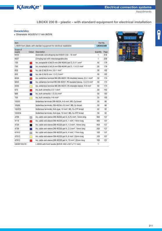
LBOXX230Bgrp
211
Electrical connection systems
Assortments
LBOXX 230 B - plastic - with standard equipment for electrical installation
Characteristics
▪ Dimensions: 442x357x117 mm (W/D/H)
Item Part No.
L-BOXX from plastic with standard equipment for electrical installation. LBOXX230B
Scope of supply Colour Description Quantity Page
K432 Automatic wire stripping tool K43/2 0.02 - 10 mm² 1 516
K507 Crimping tool with interchangeable dies 1 258
720 Ins. receptacle 6.3x0.8 mm DIN 46245 part 3, 0.5-1 mm² 50 179
730 Ins. receptacle 6.3x0.8 mm DIN 46245 part 3, 1.5-2.5 mm² 50 179
820 Ins. tab 6.3x0.8 mm, 0.5-1 mm² 50 182
830 Ins. tab 6.3x0.8 mm, 1.5-2.5 mm² 50 182
6204 Ins. solderless terminal M4 DIN 46237, PA insulated sleeve, 0.5-1 mm² 50 174
6305 Ins. solderless terminal M5 DIN 46237, PA insulated sleeve, 1.5-2.5 mm² 50 174
6506 Ins. solderless terminal M6 DIN 46237, PA insulated sleeve, 4-6 mm² 50 174
670 Ins. butt connector, 0.5-1 mm² 50 183
680 Ins. butt connector, 1.5-2.5 mm² 50 183
700 Ins. butt connector, 4-6 mm² 25 183
16505 Solderless terminals DIN 46234, 4-6 mm², M5, Cu tinned 50 88
16506 Solderless terminals, DIN 46234, 4-6 mm², M6, Cu tinned 50 88
1652C5 Solderless terminals, fork-type, 10 mm², M5, Cu-ETP tinned 50 92
1652C6 Solderless terminals, fork-type, 10 mm², M6, Cu-ETP tinned 50 92
4708 Ins. cable end-sleeve DIN 46228 part 4, 0.75 mm², 14mm long 400 157
4718 Ins. cable end-sleeve DIN 46228 part 4, 1 mm², 14mm long 400 157
4728 Ins. cable end-sleeve DIN 46228 part 4, 1.5 mm², 14mm long 400 157
4738 Ins. cable end-sleeve DIN 46228 part 4, 2.5 mm², 14mm long 200 157
47410 Ins. cable end-sleeve DIN 46228 part 4, 4 mm², 17mm long 100 157
47512 Ins. cable end-sleeve DIN 46228 part 4, 6 mm², 20mm long 100 157
47612 Ins. cable end-sleeve DIN 46228 part 4, 10 mm², 22mm long 100 157
LBOXX102LFG L-BOXX with front handle (W/D/H: 442 x 357 x 117 mm) 1
Klauke Hauptkatalog EN_DIN A5.indb 211 07.10.2014 12:17:42
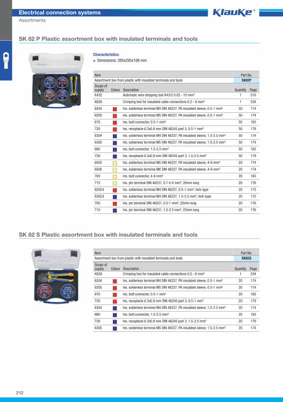
SK82Pgrp
SK82Sgrp
212
Electrical connection systems
Assortments
SK 82 P Plastic assortment box with insulated terminals and tools
Characteristics
▪ Dimensions: 395x295x106 mm
Item Part No.
Assortment box from plastic with insulated terminals and tools SK82P
Scope of supply Colour Description Quantity Page
K432 Automatic wire stripping tool K43/2 0.02 - 10 mm² 1 516
K82A Crimping tool for insulated cable connections 0,5 - 6 mm² 1 234
6204 Ins. solderless terminal M4 DIN 46237, PA insulated sleeve, 0.5-1 mm² 50 174
6205 Ins. solderless terminal M5 DIN 46237, PA insulated sleeve, 0.5-1 mm² 50 174
670 Ins. butt connector, 0.5-1 mm² 50 183
720 Ins. receptacle 6.3x0.8 mm DIN 46245 part 3, 0.5-1 mm² 50 179
6304 Ins. solderless terminal M4 DIN 46237, PA insulated sleeve, 1.5-2.5 mm² 50 174
6305 Ins. solderless terminal M5 DIN 46237, PA insulated sleeve, 1.5-2.5 mm² 50 174
680 Ins. butt connector, 1.5-2.5 mm² 50 183
730 Ins. receptacle 6.3x0.8 mm DIN 46245 part 3, 1.5-2.5 mm² 50 179
6505 Ins. solderless terminal M5 DIN 46237, PA insulated sleeve, 4-6 mm² 20 174
6506 Ins. solderless terminal M6 DIN 46237, PA insulated sleeve, 4-6 mm² 20 174
700 Ins. butt connector, 4-6 mm² 20 183
715 Ins. pin terminal DIN 46231, 0.1-0.4 mm², 26mm long 20 176
620C4 Ins. solderless terminal M4 DIN 46237, 0.5-1 mm², fork-type 20 175
630C4 Ins. solderless terminal M4 DIN 46237, 1.5-2.5 mm², fork-type 20 175
705 Ins. pin terminal DIN 46231, 0.5-1 mm², 22mm long 20 176
710 Ins. pin terminal DIN 46231, 1.5-2.5 mm², 23mm long 20 176
SK 82 S Plastic assortment box with insulated terminals and tools
Item Part No.
Assortment box from plastic with insulated terminals and tools SK82S
Scope of supply Colour Description Quantity Page
K82A Crimping tool for insulated cable connections 0,5 - 6 mm² 1 234
6204 Ins. solderless terminal M4 DIN 46237, PA insulated sleeve, 0.5-1 mm² 20 174
6205 Ins. solderless terminal M5 DIN 46237, PA insulated sleeve, 0.5-1 mm² 20 174
670 Ins. butt connector, 0.5-1 mm² 20 183
720 Ins. receptacle 6.3x0.8 mm DIN 46245 part 3, 0.5-1 mm² 20 179
6304 Ins. solderless terminal M4 DIN 46237, PA insulated sleeve, 1.5-2.5 mm² 20 174
680 Ins. butt connector, 1.5-2.5 mm² 20 183
730 Ins. receptacle 6.3x0.8 mm DIN 46245 part 3, 1.5-2.5 mm² 20 179
6305 Ins. solderless terminal M5 DIN 46237, PA insulated sleeve, 1.5-2.5 mm² 20 174
Klauke Hauptkatalog EN_DIN A5.indb 212 07.10.2014 12:17:42
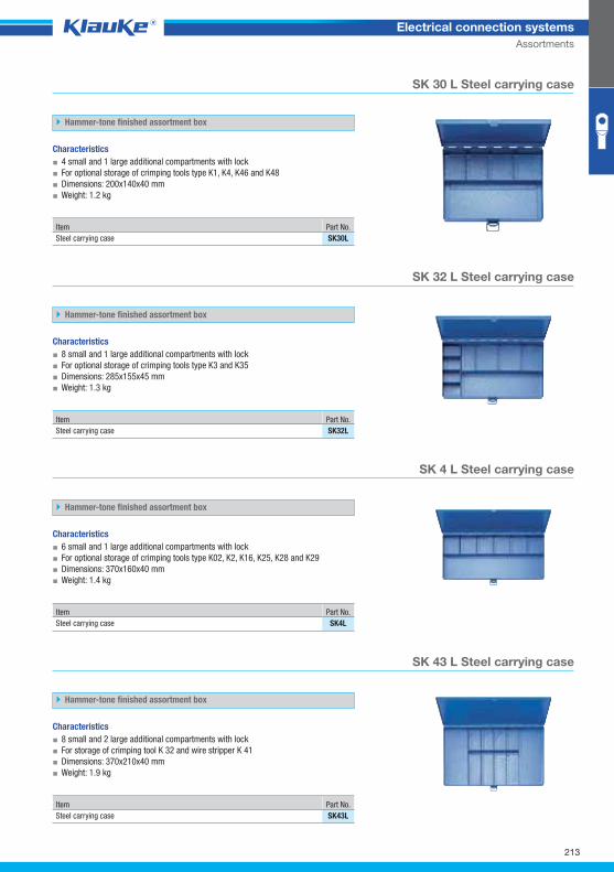
SK30Lgrp
SK32Lgrp
SK4Lgrp
SK43Lgrp
213
Electrical connection systems
Assortments
SK 30 L Steel carrying case
Hammer-tone finished assortment box
Characteristics
▪ 4 small and 1 large additional compartments with lock
▪ For optional storage of crimping tools type K1, K4, K46 and K48
▪ Dimensions: 200x140x40 mm
▪ Weight: 1.2 kg
Item Part No.
Steel carrying case SK30L
SK 32 L Steel carrying case
Hammer-tone finished assortment box
Characteristics
▪ 8 small and 1 large additional compartments with lock
▪ For optional storage of crimping tools type K3 and K35
▪ Dimensions: 285x155x45 mm
▪ Weight: 1.3 kg
Item Part No.
Steel carrying case SK32L
SK 4 L Steel carrying case
Hammer-tone finished assortment box
Characteristics
▪ 6 small and 1 large additional compartments with lock
▪ For optional storage of crimping tools type K02, K2, K16, K25, K28 and K29
▪ Dimensions: 370x160x40 mm
▪ Weight: 1.4 kg
Item Part No.
Steel carrying case SK4L
SK 43 L Steel carrying case
Hammer-tone finished assortment box
Characteristics
▪ 8 small and 2 large additional compartments with lock
▪ For storage of crimping tool K 32 and wire stripper K 41
▪ Dimensions: 370x210x40 mm
▪ Weight: 1.9 kg
Item Part No.
Steel carrying case SK43L
Klauke Hauptkatalog EN_DIN A5.indb 213 07.10.2014 12:17:43
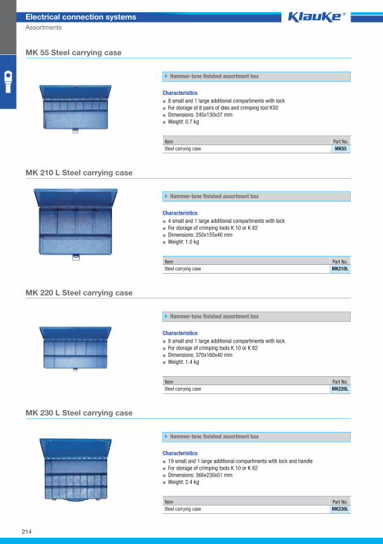
MK55grp
MK210Lgrp
MK220Lgrp
MK230Lgrp
214
Electrical connection systems
Assortments
MK 55 Steel carrying case
Hammer-tone finished assortment box
Characteristics
▪ 8 small and 1 large additional compartments with lock
▪ For storage of 8 pairs of dies and crimping tool K50
▪ Dimensions: 245x130x37 mm
▪ Weight: 0.7 kg
Item Part No.
Steel carrying case MK55
MK 210 L Steel carrying case
Hammer-tone finished assortment box
Characteristics
▪ 4 small and 1 large additional compartments with lock
▪ For storage of crimping tools K 10 or K 82
▪ Dimensions: 250x155x40 mm
▪ Weight: 1.0 kg
Item Part No.
Steel carrying case MK210L
MK 220 L Steel carrying case
Hammer-tone finished assortment box
Characteristics
▪ 8 small and 1 large additional compartments with lock
▪ For storage of crimping tools K 10 or K 82
▪ Dimensions: 370x160x40 mm
▪ Weight: 1.4 kg
Item Part No.
Steel carrying case MK220L
MK 230 L Steel carrying case
Hammer-tone finished assortment box
Characteristics
▪ 19 small and 1 large additional compartments with lock and handle
▪ For storage of crimping tools K 10 or K 82
▪ Dimensions: 366x230x51 mm
▪ Weight: 2.4 kg
Item Part No.
Steel carrying case MK230L
Klauke Hauptkatalog EN_DIN A5.indb 214 07.10.2014 12:17:43
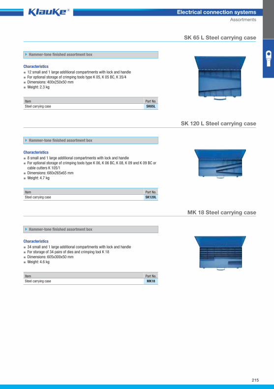
SK65Lgrp
SK120Lgrp
MK18grp
215
Electrical connection systems
Assortments
SK 65 L Steel carrying case
Hammer-tone finished assortment box
Characteristics
▪ 12 small and 1 large additional compartments with lock and handle
▪ For optional storage of crimping tools type K 05, K 05 BC, K 35/4
▪ Dimensions: 400x250x50 mm
▪ Weight: 2.3 kg
Item Part No.
Steel carrying case SK65L
SK 120 L Steel carrying case
Hammer-tone finished assortment box
Characteristics
▪ 8 small and 1 large additional compartments with lock and handle
▪ For optional storage of crimping tools type K 06, K 06 BC, K 08, K 09 and K 09 BC or
cable cutters K 105/1
▪ Dimensions: 680x265x65 mm
▪ Weight: 4.7 kg
Item Part No.
Steel carrying case SK120L
MK 18 Steel carrying case
Hammer-tone finished assortment box
Characteristics
▪ 34 small and 1 large additional compartments with lock and handle
▪ For storage of 34 pairs of dies and crimping tool K 18
▪ Dimensions: 605x300x50 mm
▪ Weight: 4.6 kg
Item Part No.
Steel carrying case MK18
Klauke Hauptkatalog EN_DIN A5.indb 215 07.10.2014 12:17:43
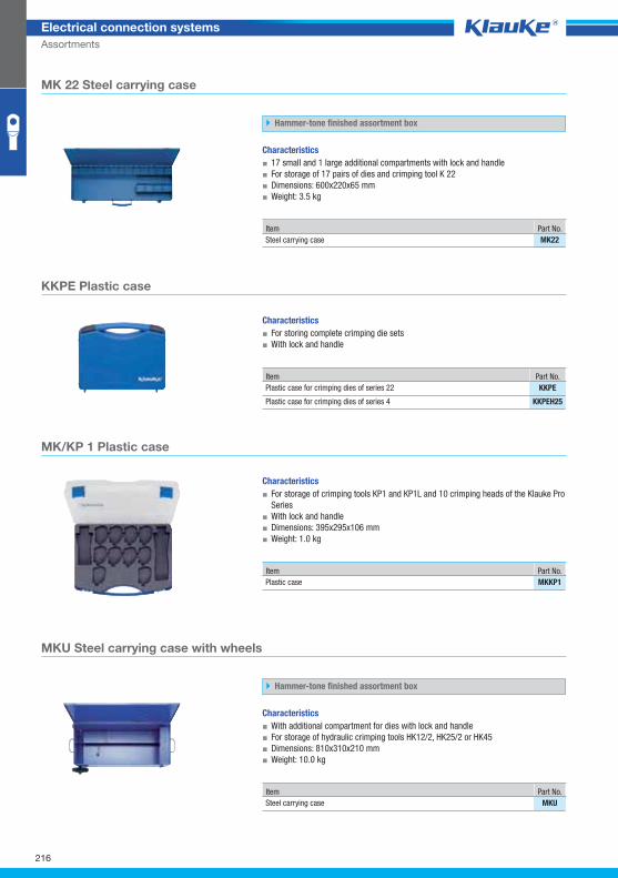
MK22grp
KKPEgrp
MKKP1grp
MKUgrp
216
Electrical connection systems
Assortments
MK 22 Steel carrying case
Hammer-tone finished assortment box
Characteristics
▪ 17 small and 1 large additional compartments with lock and handle
▪ For storage of 17 pairs of dies and crimping tool K 22
▪ Dimensions: 600x220x65 mm
▪ Weight: 3.5 kg
Item Part No.
Steel carrying case MK22
KKPE Plastic case
Characteristics
▪ For storing complete crimping die sets
▪ With lock and handle
Item Part No.
Plastic case for crimping dies of series 22 KKPE
Plastic case for crimping dies of series 4 KKPEH25
MK/KP 1 Plastic case
Characteristics
▪ For storage of crimping tools KP1 and KP1L and 10 crimping heads of the Klauke Pro
Series
▪ With lock and handle
▪ Dimensions: 395x295x106 mm
▪ Weight: 1.0 kg
Item Part No.
Plastic case MKKP1
MKU Steel carrying case with wheels
Hammer-tone finished assortment box
Characteristics
▪ With additional compartment for dies with lock and handle
▪ For storage of hydraulic crimping tools HK12/2, HK25/2 or HK45
▪ Dimensions: 810x310x210 mm
▪ Weight: 10.0 kg
Item Part No.
Steel carrying case MKU
Klauke Hauptkatalog EN_DIN A5.indb 216 07.10.2014 12:17:44
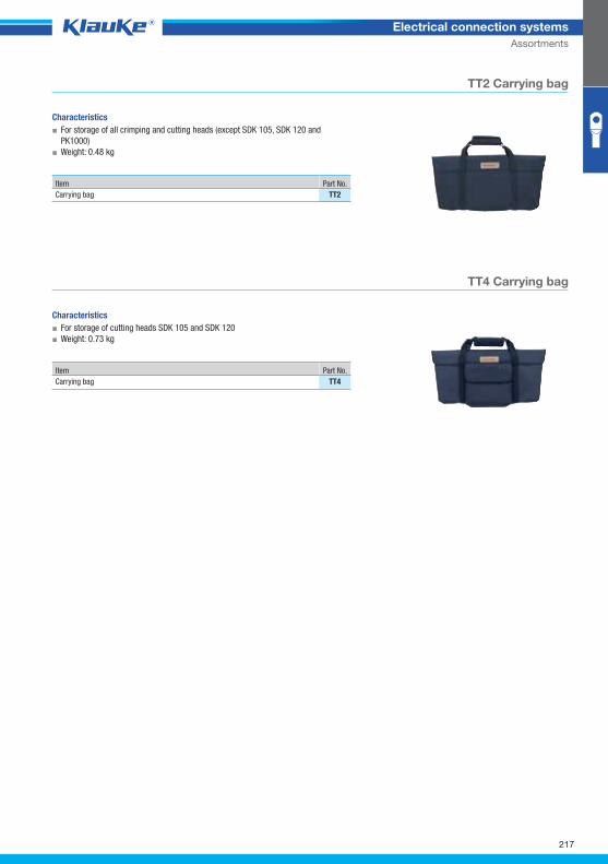
TT2grp
TT4grp
217
Electrical connection systems
Assortments
TT2 Carrying bag
Characteristics
▪ For storage of all crimping and cutting heads (except SDK 105, SDK 120 and
PK1000)
▪ Weight: 0.48 kg
Item Part No.
Carrying bag TT2
TT4 Carrying bag
Characteristics
▪ For storage of cutting heads SDK 105 and SDK 120
▪ Weight: 0.73 kg
Item Part No.
Carrying bag TT4
Klauke Hauptkatalog EN_DIN A5.indb 217 07.10.2014 12:17:44