Embed Size (px)
Citation preview
Electrical Circuit TroubleshootingAPTA Bus Technical Maintenance Committee Webinar M a r c h 3 1 , 2 0 2 0

Welcome
Lisa JerramDirector-Bus Programs and Emerging Vehicle TechnologiesAPTAWashington, DC
Staff AdvisorAPTA Bus Technical Maintenance Committee
Electrical Circuit Troubleshooting Webinar I 2
Housekeeping
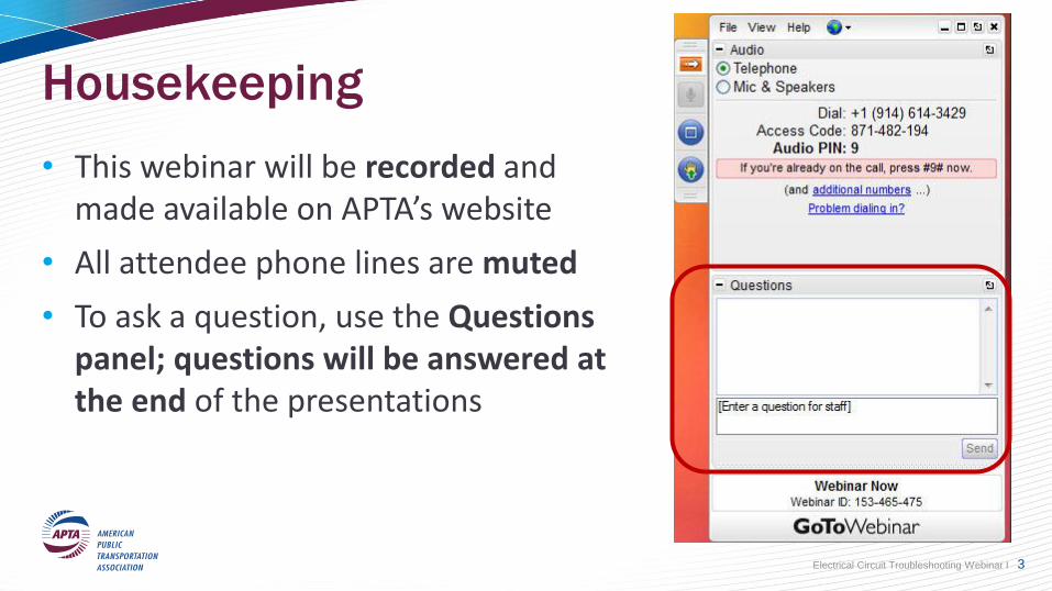
• This webinar will be recorded and made available on APTA’s website
• All attendee phone lines are muted
• To ask a question, use the Questions panel; questions will be answered at the end of the presentations
Electrical Circuit Troubleshooting Webinar I 3
Moderator
Obed MejiaSenior Bus Equipment Maintenance Instructor LA MetroLos Angeles, CA
Vice Chair-Webinars APTA Bus Technical Maintenance Committee
Electrical Circuit Troubleshooting Webinar I 4
Objectives
Attendees will learn about:
1. Performing circuit testing to identify open circuit
2. Performing a voltage drop test to identify high resistance conditions
3. Identifying faulty ground conditions
Electrical Circuit Troubleshooting Webinar I 5
Presenter
Andrew Warren, Jr.Equipment Maintenance InstructorLA MetroLos Angeles, CA
Electrical Circuit Troubleshooting Webinar I 6

Introduction The most common electrical circuit faults you will encounter when working on bus electrical systems are: open circuits; short circuits; and high resistance.
Open Circuit - any break (open) in the current path of a series circuit makes the entire circuit inoperative. In a parallel circuit, only the branch effected by the open is inoperative.
Short Circuit - this can be a short-to-ground or short-to-voltage. This may cause a component to continuously operate regardless of switch position, or a fuse to repeatedly blow, depending on the fault.
Unwanted Resistance - the load device does not receive the proper voltage/current to perform work and may operate sluggishly, dim, or not operate at all.
Electrical Circuit Troubleshooting Webinar I 7
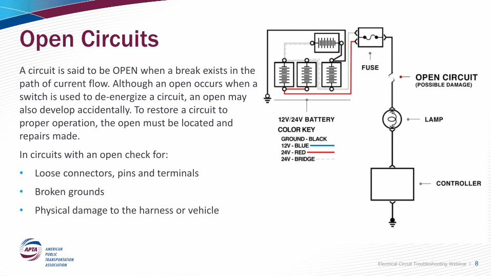
Open CircuitsA circuit is said to be OPEN when a break exists in the path of current flow. Although an open occurs when a switch is used to de-energize a circuit, an open may also develop accidentally. To restore a circuit to proper operation, the open must be located and repairs made.
In circuits with an open check for:
• Loose connectors, pins and terminals
• Broken grounds
• Physical damage to the harness or vehicle
Electrical Circuit Troubleshooting Webinar I 8
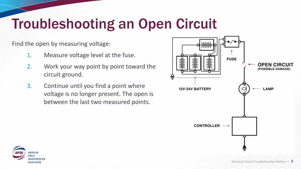
Troubleshooting an Open Circuit
Find the open by measuring voltage:
1. Measure voltage level at the fuse.
2. Work your way point by point toward the circuit ground.
3. Continue until you find a point where voltage is no longer present. The open is between the last two measured points.
Electrical Circuit Troubleshooting Webinar I 9
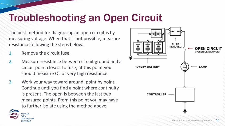
Troubleshooting an Open Circuit
The best method for diagnosing an open circuit is by measuring voltage. When that is not possible, measure resistance following the steps below.
1. Remove the circuit fuse.
2. Measure resistance between circuit ground and a circuit point closest to fuse; at this point you should measure OL or very high resistance.
3. Work your way toward ground, point by point. Continue until you find a point where continuity is present. The open is between the last two measured points. From this point you may have to further isolate using the method above.
Electrical Circuit Troubleshooting Webinar I 10
Short CircuitsA short circuit is a fault that creates an unwanted path between two parts of a circuit, or a short can bridge two circuits together.
A short can be:
• An unwanted path between part of a circuit and ground (short to ground).
• An unwanted path between two separate circuits (short to power/wire to wire).
• An unwanted path between two parts of a circuit, some of the loads may be bypassed on circuit.
• An unwanted current path inside a component, internal resistance of load too low.
Most common short circuit is short to ground. This short typically blows the circuit fuse or pops the breaker.
Note: It may not be possible to troubleshoot the circuit under its own power.
Electrical Circuit Troubleshooting Webinar I 11
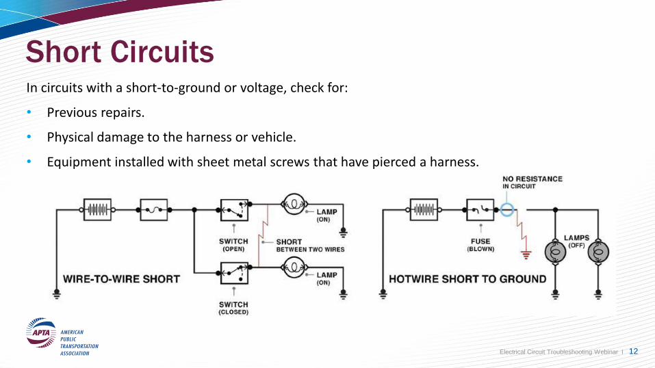
Short CircuitsIn circuits with a short-to-ground or voltage, check for:
• Previous repairs.
• Physical damage to the harness or vehicle.
• Equipment installed with sheet metal screws that have pierced a harness.
Electrical Circuit Troubleshooting Webinar I 12
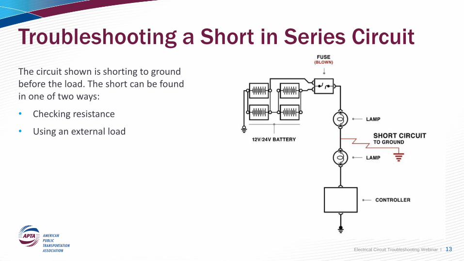
Troubleshooting a Short in Series Circuit
The circuit shown is shorting to ground before the load. The short can be found in one of two ways:
• Checking resistance
• Using an external load
Electrical Circuit Troubleshooting Webinar I 13
Troubleshooting a Short in Series Circuit –
External Load
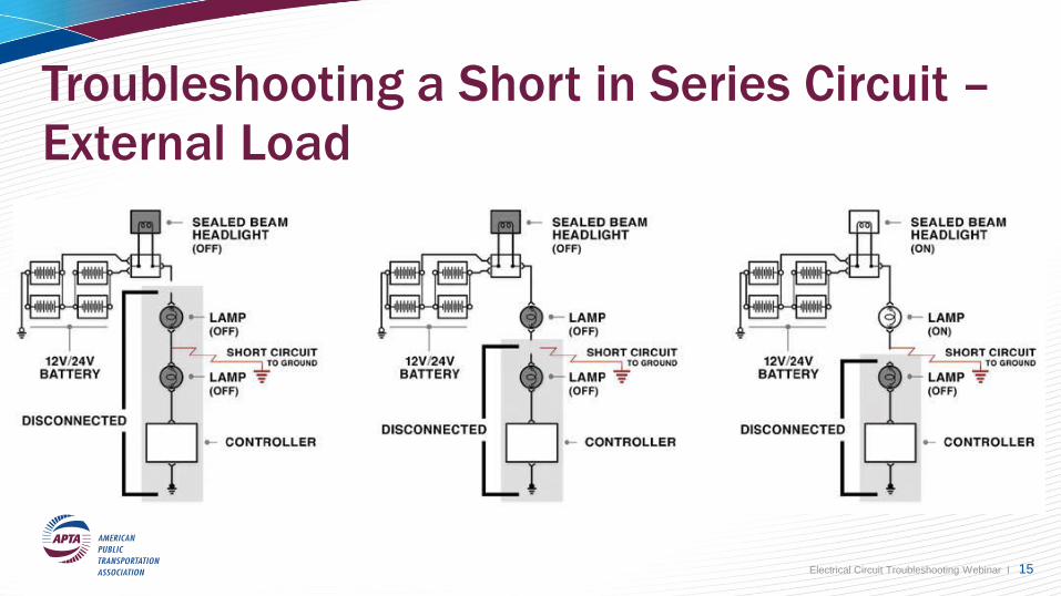
For some faults, using tools other than a DMM may help diagnose a fault faster. If there is a short to ground in a series circuit, a test light may help you pinpoint the short location.
1. Remove the fuse.
2. Jumper in an external load (a light works well for this).
3. Apply power to the circuit- the light will turn ON.
4. Start by disconnecting the connection point closest to the external load and work your way towards ground.
5. The light will continue to remain lit when you disconnect the section past the short.
Electrical Circuit Troubleshooting Webinar I 14
Troubleshooting a Short in Series Circuit –
External Load
Electrical Circuit Troubleshooting Webinar I 15
Troubleshooting a Short in Series Circuit –
Measuring ResistanceIf a circuit has a high resistance, then we could use a DMM to help locate which part of the circuit has the fault. Set the DMM to read Ohms, and then remove all voltage from the circuit by disconnecting the batteries or removing the fuse.
1. Disconnect the connection point closest to the power source.
2. Connect the meter to the connection point closest to the power source and ground.
Note: The measured resistance here should be close to 0Ω. Leave the meter in place.
3. Disconnect the next accessible connection point moving towards ground.
4. The point where continuity is lost is where the short is located.
Electrical Circuit Troubleshooting Webinar I 16
Unwanted Resistance Circuit FaultsUnwanted resistance in a circuit can prevent it from operating normally.
• Unwanted resistance in a circuit can be a poor connection, burned pin, corroded wire / terminal or a faulty component.
• Normal Resistance in a healthy circuit should be very close to 0 ohms using no voltage when the circuit in ON. Higher resistance indicates a possible problem. A dim bulb can be an indicator of high resistance.
This unwanted resistance can best be detected when the circuit is ON by performing voltage drop measurements.
Electrical Circuit Troubleshooting Webinar I 17
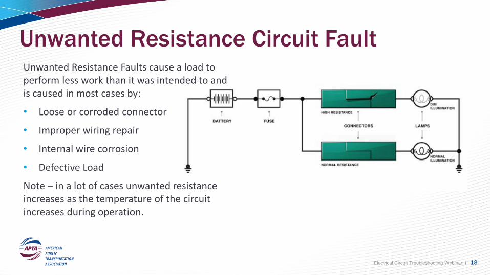
Unwanted Resistance Circuit FaultUnwanted Resistance Faults cause a load to perform less work than it was intended to and is caused in most cases by:
• Loose or corroded connector
• Improper wiring repair
• Internal wire corrosion
• Defective Load
Note – in a lot of cases unwanted resistance increases as the temperature of the circuit increases during operation.
Electrical Circuit Troubleshooting Webinar I 18
Unwanted Resistance Circuit Fault
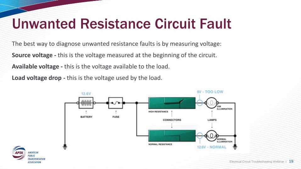
The best way to diagnose unwanted resistance faults is by measuring voltage:
Source voltage - this is the voltage measured at the beginning of the circuit.
Available voltage - this is the voltage available to the load.
Load voltage drop - this is the voltage used by the load.
Electrical Circuit Troubleshooting Webinar I 19
Voltage Drop Measurements
Measuring voltage drop is one of the most useful tests you can perform. A voltage drop test checks for loss of voltage in each portion of the circuit while the circuit is connected, powered and operated.
Note: Voltage drop testing requires you to back probe, all components remain connected during testing.
A voltage drop test is done as follows:
1. Place the positive lead in the most positive section of the circuit you are testing.
2. Place the ground lead on the most negative section of the circuit you are testing.
3. Operate the circuit with the meter leads in place and note the reading.
Remember that voltage dropped is voltage consumed by resistance in the circuit.
Electrical Circuit Troubleshooting Webinar I 20
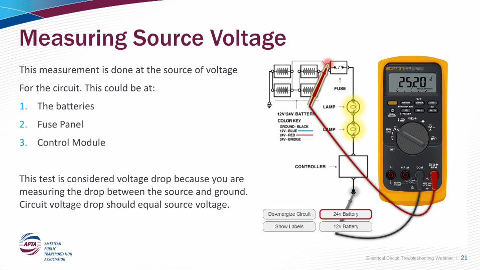
Measuring Source Voltage
This measurement is done at the source of voltage
For the circuit. This could be at:
1. The batteries
2. Fuse Panel
3. Control Module
This test is considered voltage drop because you are measuring the drop between the source and ground. Circuit voltage drop should equal source voltage.
Electrical Circuit Troubleshooting Webinar I 21
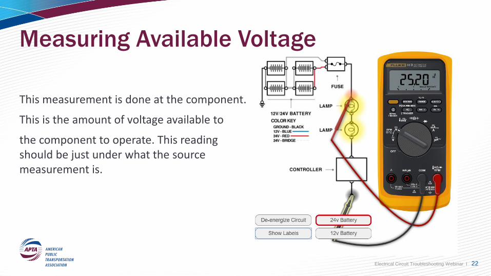
Measuring Available Voltage
This measurement is done at the component.
This is the amount of voltage available to
the component to operate. This reading should be just under what the source measurement is.
Electrical Circuit Troubleshooting Webinar I 22
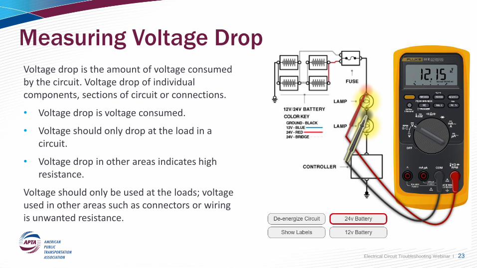
Measuring Voltage Drop
Voltage drop is the amount of voltage consumed by the circuit. Voltage drop of individual components, sections of circuit or connections.
• Voltage drop is voltage consumed.
• Voltage should only drop at the load in a circuit.
• Voltage drop in other areas indicates high resistance.
Voltage should only be used at the loads; voltage used in other areas such as connectors or wiring is unwanted resistance.
Electrical Circuit Troubleshooting Webinar I 23
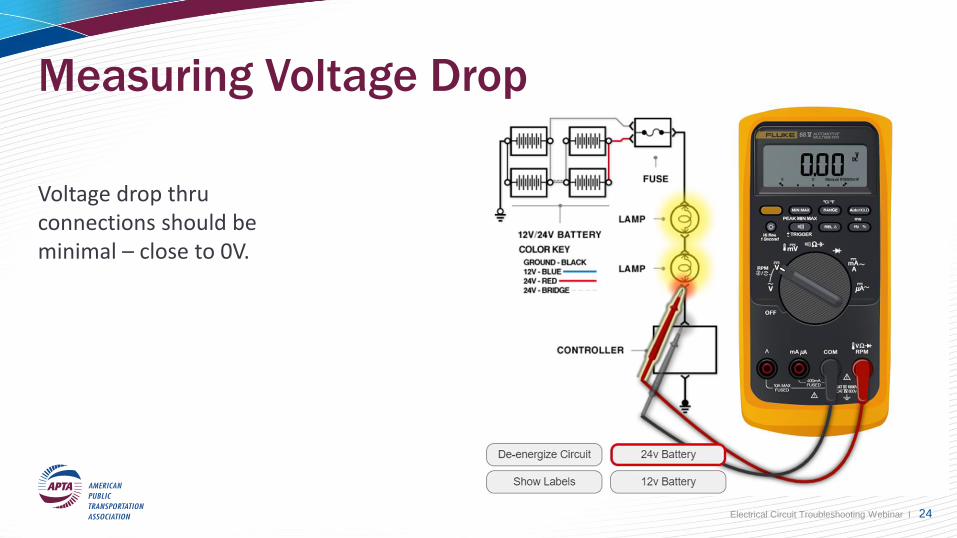
Measuring Voltage Drop
Voltage drop thru connections should be minimal – close to 0V.
Electrical Circuit Troubleshooting Webinar I 24
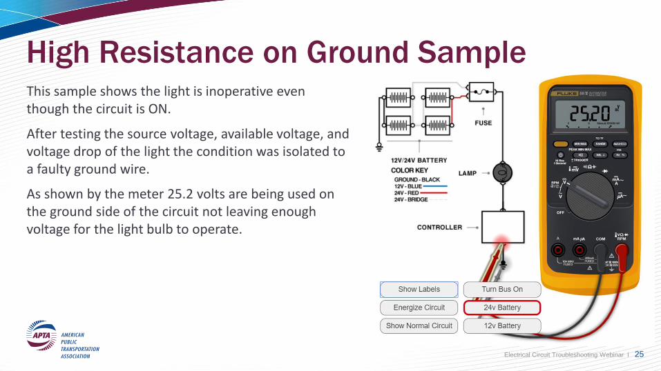
High Resistance on Ground SampleThis sample shows the light is inoperative even though the circuit is ON.
After testing the source voltage, available voltage, and voltage drop of the light the condition was isolated to a faulty ground wire.
As shown by the meter 25.2 volts are being used on the ground side of the circuit not leaving enough voltage for the light bulb to operate.
Electrical Circuit Troubleshooting Webinar I 25
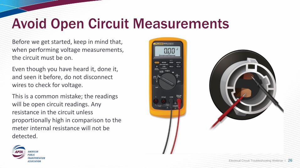
Avoid Open Circuit MeasurementsBefore we get started, keep in mind that, when performing voltage measurements, the circuit must be on.
Even though you have heard it, done it, and seen it before, do not disconnect wires to check for voltage.
This is a common mistake; the readings will be open circuit readings. Any resistance in the circuit unless proportionally high in comparison to the meter internal resistance will not be detected.
Electrical Circuit Troubleshooting Webinar I 26
Open Circuit Reading – Bad Experience Condition: No Start - Repeat Road Calls.
A mechanic is working on a No Start condition on a Cummins gas engine. During the diagnosis, an active code for throttle plate
position sensor low input voltage is found. As part of the diagnostic procedure, the mechanic checks for available voltage to the throttle
plate and measures 12.5V. Since there is full battery voltage available to the throttle, the mechanic concludes that the throttle plate is
defective and needs replacement. The mechanic replaces the throttle plate, but the No Start condition does not go away.
What did the mechanic do wrong? As part of the diagnostic process, the mechanic checked available voltage to the throttle plate and
found 12.5 volts. It is here where a serious mistake was made: when the mechanic made the measurement, the throttle plate connector
was disconnected. As some of you may know, it is easier to disconnect this component and check it, than it is to back probe it. The
reading of 12.5 volts was actually an open circuit reading which did not reflect high resistance in the circuit.
When another mechanic took over the repair, the same diagnostic procedure was performed. This time however, available voltage was
checked with the throttle plate connected, and the measured voltage was 3V, indicating high resistance on the supply wire. Further
testing revealed a loose connector behind the fuse box. An easy replacement of the connector terminal pins took care of the problem.
So remember, when measuring voltage on any circuit, NEVER OPEN THE CIRCUIT.
Electrical Circuit Troubleshooting Webinar I 27
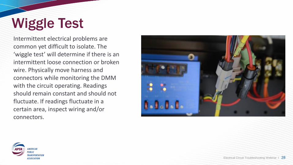
Wiggle Test Intermittent electrical problems are common yet difficult to isolate. The ‘wiggle test’ will determine if there is an intermittent loose connection or broken wire. Physically move harness and connectors while monitoring the DMM with the circuit operating. Readings should remain constant and should not fluctuate. If readings fluctuate in a certain area, inspect wiring and/or connectors.
Electrical Circuit Troubleshooting Webinar I 28
Summary
Proper diagnosis of electrical circuits is key to successfully repairing buses the first time.
Remember! All diagnostic tests done correctly will get you to the problem.
Our preference is to perform voltage test whenever possible since the circuit in ON while is being tested. This simulates more closely a real-world situation.
Electrical Circuit Troubleshooting Webinar I 29
Thank You!
A recording of this webinar will be available on www.apta.com.
Please complete the post webinar evaluation. A link to the online evaluation will be emailed to you this afternoon.
Electrical Circuit Troubleshooting Webinar I 30