Embed Size (px)
Citation preview

Electrical and Electronics Engineering: An International Journal (ELELIJ) Vol 2, No 2, May 2013
1
PROTECTION COORDINATION OF DISTRIBUTION
SYSTEMS EQUIPPED WITH DISTRIBUTED
GENERATIONS
Ahmed Kamel
1, M. A. Alaam
2, Ahmed M. Azmy
3 and A. Y. Abdelaziz
4
1South Delta Electricity Distribution Company, Tanta, Egypt
Department of Electrical Power & Machines Engineering, Faculty of
Engineering, Tanta University, Tanta, Egypt [email protected]
[email protected] 4Electrical Power & Machines Department, Faculty of Engineering, Ain Shams
University, Cairo, Egypt [email protected]
ABSTRACT
Coordination among protective devices in distribution systems will be affected by adding distributed
generators (DGs) to the existing network. That is attributed to the changes in power flow directions and
fault currents magnitudes and directions due to the insertion of DG units in the distribution system, which
may cause mis-coordination between protection devices. This paper presents an approach to overcome the
impacts of DG units insertion on the protection system and to avoid the mis-coordination problem. The
proposed approach depends on activating the directional protection feature which is available in most
types of modern microprocessor-based reclosers. This will be accompanied by an updating of relays and
reclosers settings to achieve the correct coordination. It's clear that this approach do not need any extra
costs or any extra equipment to be installed in the distribution system. An existing 11 kV feeder, simulated
on ETAP package, is used to prove the suitability and effectiveness of the proposed approach. The results
ensure the possibility of achieving the proper coordination between protective devices after inserting DG
units if the proper and suitable settings of these devices are realized.
KEYWORDS
Protection Coordination, Distribution Networks, Distributed Generation (DG), ETAP, Recloser.
1. INTRODUCTION
Connection of DGs to distribution systems brings up several environmental, economical and
technical benefits such as reduced environmental pollution, improved voltage profile, reduced
electric losses, increased distribution system capacity and increased system reliability [1]. The
previous studies [2-6] have shown that DGs insertion in distribution systems changes short circuit
current levels and direction of power flow. This may cause significant impact on the protection
system such as protection-devices mis-coordination and asynchronous reclosing. Protection
system for distribution networks uses simple protection devices such as over current relays,
reclosers and fuses, where the coordination between these devices is well established assuming
radial systems. Penetration of DGs in distribution system should be accompanied with changes in
the protection scheme to overcome the previously mentioned impacts.

Electrical and Electronics Engineering: An International Journal (ELELIJ) Vol 2, No 2, May 2013
2
N. Hadjsaid and et al in [7] present an example to study the impact of DG penetration in
distribution systems on the fault currents passing through protection devices. They suggested that
the protection coordination should be checked after the connection of each DG unit. The effect of
distributed generation on fuse-recloser coordination in distribution systems was studied in [8 and
9], where it is stated that DG connection can result in loosing coordination between these devices.
An adaptive protection scheme for optimal coordination of over-current relays taking in to
account DG units insertion was introduced in [10], where new relay setting technique was
implemented for changes in loads and generation. A study for the technical impacts of distributed
generation on fuse based protection and an approach to avoid DG impacts was introduced in [11].
A solution for the coordination problem was introduced in [12] based on dividing the distribution
system into zones separated by remotely controlled breakers. The faulted zone is disconnected by
tripping the appropriate breaker. The disadvantage of this approach is its high cost and
complexity of communication and control especially for long feeders. An expert system for
protective-devices coordination in radial distribution networks with small power producers was
introduced in [13]. This presents a very useful approach for coordinating multiple protective
relays in a distribution system. However, computer program is just the assistant for the short
circuit calculation. The configurations of the protective devices still have to be specified by
human. So, the expert system is just the alternative way for the protective device coordination.
Artificial Neural Network (ANN) has been used in protection coordination [14 and 15]. ANN
may be helpful in calculating power flow and fault levels, but coordination settings may be too
complicated for ANN to deal with because they depend primarily on expertise of grid operator. A
protection scheme for a distribution network with DG units considers the application of multi-
layer perceptron neural network (MLPNN) for fault location [16] was introduced. However, due
to the structure and training algorithm of the MLPNN, the speed of this method is not suitable for
fast and accurate protection.
A classification technique for recloser-fuse coordination in distribution systems with distributed
generation has been proposed [17]. This approach is based on two main steps: protection
coordination assessment and protection coordination improvement. In the coordination
assessment step, the coordination status after integrating DG to the system is classified as either
coordination holds or coordination lost. The coordination improvement step is based on
decreasing the number of cases where coordination is lost. The main disadvantage of this
approach is its capability to decrease the number of cases where coordination is lost. This means
that it does not present a solution for all possible faults with all possible DG locations and it does
not take into account insertion of more than one DG. An expert system for protection
coordination of distribution system with distributed generators was presented in [18]. The expert
system employs a knowledge base and inference process to improve the coordination settings of
protective devices to accommodate the penetration of distributed generators. However, this
system produces preliminary settings and still need to be revised by an expert user. The authors
proposed in [19] an adaptive current protection scheme for distribution systems with distributed
generation. The scope of this scheme concerned only with the coordination between protective
relays but it does not take in to account coordination between relays and other protection devices
used in the distribution systems such as fuses and reclosers. A neural network and backtracking
based protection coordination scheme was used for distribution system with distributed
generation in [20]. An automated fault location method is developed using a two stage radial
basis function neural network (RBFNN) in which the first RBFNN determines the fault distance
from each source while the second RBFNN identifies the exact faulty line. After identifying the
exact faulty line, protection relay coordination is implemented. A new protection coordination
strategy using the backtracking algorithm is proposed, which considers the main protection

Electrical and Electronics Engineering: An International Journal (ELELIJ) Vol 2, No 2, May 2013
3
algorithm to coordinate the operating states of relays so as to isolate the faulty line. Then, a
backup protection algorithm is considered to complete the protection coordination scheme for
isolating the malfunction relays of the main protection system. The main disadvantage of using
neural networks in protection systems coordination is the low speed of data processing and
communication, which is not suitable for fast and accurate protection decision.
In this paper, the impact of DG on the coordination of protection system in distribution networks
will be investigated. In addition, a proposed approach is introduced to overcome the protection-
devices mis-coordination problem, which results from the DGs insertion in distribution networks.
The most severe impact of DGs insertion is the great change in power flow and fault currents
directions, so obviously the solution of the mis-coordination problem will be the use of
directional protection. By activating this feature in reclosers and updating the fuses sizes and
protection devices settings in a proper way, the mis-coordination problem can be easily solved
without replacing the existing protective devices or changing the coordination methodology.
2. DISTRIBUTION SYSTEM DESCRIPTION
To study the impact of DG insertion in distribution systems on the protection coordination and to
check the performance, accuracy and suitability of the proposed approach, a real distribution
system is used. The system is a 75 node, 11 kV distribution feeder, which is an actual feeder in
Elgharbia electricity sector- Kotour city. The single line diagram and the protection devices
locations for this feeder are shown in Figure 1. This feeder has been simulated using ETAP 6
package to perform load flow, short circuit and protection coordination studies.
Figure 1. Single line diagram the real 11 kV distribution feeder

Electrical and Electronics Engineering: An International Journal (ELELIJ) Vol 2, No 2, May 2013
4
3. COORDINATION STUDY FOR THE DISTRIBUTION SYSTEM WITHOUT DG
The total connected load of this feeder is 6536 kVA and hence, the maximum full load current is
344 A. Overcurrent protection setting of the relay should be taken as 1.25 of this current [21],
which equals 430 A. The total connected load downstream the recloser is 4514 kVA, thus, the
recloser downstream maximum full load current is 237A. Overcurrent protection setting of the
recloser should be taken as 1.25 of this current, which is 297A. Fuse size will be also taken as
1.25 of the maximum full load current of the connected load on its lateral [21]. In order to
coordinate these devices with each other, the difference between the operating time of the primary
and backup protection should always be greater than 200 ms [21]. According to the previous
setting values and fuses sizes, the original coordination between the protection devices is shown
in Figure 2.
Figure 2. Original coordination without DG units
From the protection point of view, this distribution system is divided into 20 protection zones.
Relay protection zone is from node 1 to node 32 on the main feeder, while recloser protection
zone is from node 32 to node 75 on the main feeder. In addition, each one of the 18 laterals
represents a separate protection zone and will be named as its fuse name. From the coordination
curves in Figure 2, Table 1 can be derived to summarize the primary and the backup protection
devices for each zone.

Electrical and Electronics Engineering: An International Journal (ELELIJ) Vol 2, No 2, May 2013
5
Protection
Zone
Primary
protection
device
Backup
protection
device
Protection
Zone
Primary
protection
device
Backup
protection
device
Relay
zone Relay
Incoming feeder
Protection F9 zone Fuse F9 Recloser
Recloser
zone Recloser Relay F10 zone Fuse F10 Recloser
F1 zone Fuse F1 Relay F11 zone Fuse F11 Recloser
F2 zone Fuse F2 Relay F12 zone Fuse F12 Recloser
F3 zone Fuse F3 Relay F13 zone Fuse F13 Recloser
F4 zone Fuse F4 Relay F14 zone Fuse F14 Recloser
F5 zone Fuse F5 Relay F15 zone Fuse F15 Recloser
F6 zone Fuse F6 Relay F16 zone Fuse F16 Recloser
F7 zone Fuse F7 Relay F17 zone Fuse F17 Recloser
F8 zone Fuse F8 Recloser F18 zone Fuse F18 Recloser
Table 1. Primary and backup protection device for each zone
From this table, it is clear that there is a good coordination between protection devices in normal
operation.
4. IMPACT OF DG ON THE PROTECTION COORDINATION
To study the impact of DG insertion on the protection coordination of the previously described
distribution feeder, two DGs are inserted in the feeder. DG1 is placed upstream the recloser at
node 11 and DG2 is placed downstream the recloser at node 46. Table 2 shows all possible faults
and the response operation of the protection system after DG insertion according to the original
coordination.
Faulted
zone
Protection system operation
Actual tripping Correct tripping
Primary Backup Primary Backup
Relay
zone
Relay Incoming feeder protection Relay Incoming feeder protection
Fuse F4 DG1 protection Fuse F4 DG1 protection
Fuse F10 Recloser Recloser Fuse F10
Recloser
zone
Fuse F4 DG1 protection Recloser Relay, fuse F4
Recloser Relay fuse F10 DG2 protection
fuse F10 DG2 protection - -
F1 zone Fuse F1 Relay, fuse F4, fuse F10 Fuse F1 Relay, fuse F4, recloser
F2 zone Fuse F2 Relay, fuse F4, fuse F10 Fuse F2 Relay, fuse F4, recloser
F3 zone Fuse F3 Relay, fuse F4, fuse F10 Fuse F3 Relay, fuse F4, recloser
F4 zone Fuse F4 Relay, fuse F10 Fuse F4 Relay, recloser
DG1
protection
- DG1
protection
-
F5 zone Fuse F5 Relay, fuse F4, fuse F10 Fuse F5 Relay, fuse F4,recloser
F6 zone Fuse F6 Relay, fuse F4, fuse F10 Fuse F6 Relay, fuse F4,recloser
F7 zone Fuse F7 Relay, fuse F4, fuse F10 Fuse F7 Relay, fuse F4,recloser
F8 zone Fuse F8 Fuse F4, recloser, fuse F10 Fuse F8 Recloser, fuse F10
Electrical and Electronics Engineering: An International Journal (ELELIJ) Vol 2, No 2, May 2013
6
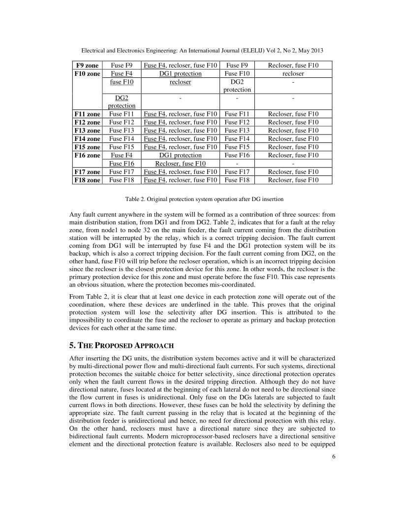
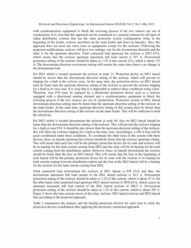
F9 zone Fuse F9 Fuse F4, recloser, fuse F10 Fuse F9 Recloser, fuse F10
F10 zone Fuse F4 DG1 protection Fuse F10 recloser
fuse F10 recloser DG2
protection
-
DG2
protection
- - -
F11 zone Fuse F11 Fuse F4, recloser, fuse F10 Fuse F11 Recloser, fuse F10
F12 zone Fuse F12 Fuse F4, recloser, fuse F10 Fuse F12 Recloser, fuse F10
F13 zone Fuse F13 Fuse F4, recloser, fuse F10 Fuse F13 Recloser, fuse F10
F14 zone Fuse F14 Fuse F4, recloser, fuse F10 Fuse F14 Recloser, fuse F10
F15 zone Fuse F15 Fuse F4, recloser, fuse F10 Fuse F15 Recloser, fuse F10
F16 zone Fuse F4 DG1 protection Fuse F16 Recloser, fuse F10
Fuse F16 Recloser, fuse F10 - -
F17 zone Fuse F17 Fuse F4, recloser, fuse F10 Fuse F17 Recloser, fuse F10
F18 zone Fuse F18 Fuse F4, recloser, fuse F10 Fuse F18 Recloser, fuse F10
Table 2. Original protection system operation after DG insertion
Any fault current anywhere in the system will be formed as a contribution of three sources: from
main distribution station, from DG1 and from DG2. Table 2, indicates that for a fault at the relay
zone, from node1 to node 32 on the main feeder, the fault current coming from the distribution
station will be interrupted by the relay, which is a correct tripping decision. The fault current
coming from DG1 will be interrupted by fuse F4 and the DG1 protection system will be its
backup, which is also a correct tripping decision. For the fault current coming from DG2, on the
other hand, fuse F10 will trip before the recloser operation, which is an incorrect tripping decision
since the recloser is the closest protection device for this zone. In other words, the recloser is the
primary protection device for this zone and must operate before the fuse F10. This case represents
an obvious situation, where the protection becomes mis-coordinated.
From Table 2, it is clear that at least one device in each protection zone will operate out of the
coordination, where these devices are underlined in the table. This proves that the original
protection system will lose the selectivity after DG insertion. This is attributed to the
impossibility to coordinate the fuse and the recloser to operate as primary and backup protection
devices for each other at the same time.
5. THE PROPOSED APPROACH
After inserting the DG units, the distribution system becomes active and it will be characterized
by multi-directional power flow and multi-directional fault currents. For such systems, directional
protection becomes the suitable choice for better selectivity, since directional protection operates
only when the fault current flows in the desired tripping direction. Although they do not have
directional nature, fuses located at the beginning of each lateral do not need to be directional since
the flow current in fuses is unidirectional. Only fuse on the DGs laterals are subjected to fault
current flows in both directions. However, these fuses can be hold the selectivity by defining the
appropriate size. The fault current passing in the relay that is located at the beginning of the
distribution feeder is unidirectional and hence, no need for directional protection with this relay.
On the other hand, reclosers must have a directional nature since they are subjected to
bidirectional fault currents. Modern microprocessor-based reclosers have a directional sensitive
element and the directional protection feature is available. Reclosers also need to be equipped
Electrical and Electronics Engineering: An International Journal (ELELIJ) Vol 2, No 2, May 2013
7
with synchronization equipment to block the reclosing process if the two sources are out of
synchronism. It is clear that this approach can be considered as a general solution for all types of
radial distribution systems that use the same protection system configuration (relay at the
beginning of the feeder, recloser anywhere on the main feeder and fuses on laterals). Also, this
approach does not need any extra costs or equipments except for the reclosers. Following the
proposed modifications, recloser will have two settings: one for the downstream direction and the
other is for the upstream direction. Total connected load upstream the recloser is 2022 kVA,
which means that the recloser upstream maximum full load current is 107 A. Overcurrent
protection setting of the recloser should be taken as 1.25 of this current [21], which is about 133
A. The downstream direction overcurrent setting will remain the same since there is no change in
the downstream load.
For DG1 which is located upstream the recloser at node 11; Protection device on DG1 lateral
should be slower than the downstream direction setting of the recloser, which will prevent its
tripping for a fault at the recloser zone. At the same time, the protection device on DG1 lateral
must be faster than the upstream direction setting of the recloser to prevent the recloser tripping
for a fault in its own zone. It is clear that it is impossible to achieve these conditions using a fuse.
Therefore, fuse F10 must be replaced by a directional protection device such as a recloser
equipped with a directional sensing element and a synchronization equipment to block the
reclosing process if the two sources are out of synchronism. Protection system at DG1 lateral
downstream direction setting must be faster than the upstream direction setting of the recloser on
the main feeder. At the same time, upstream direction setting of this system must be slower than
the downstream direction setting of the recloser on the main feeder. This will be sufficient to hold
the selectivity.
For DG2 which is located downstream the recloser at node 46; fuse on DG2 lateral should be
faster than the downstream direction setting of the recloser. This will prevent the recloser tripping
for a fault at zone F10. It should be also slower than the upstream direction setting of the recloser,
this will allow the recloser tripping for a fault at the relay zone. Accordingly, a 100 A fuse will be
good coordinated under these conditions. To coordinate the other fuses in the system with these
devices, fuses on laterals upstream the recloser should be faster than the recloser upstream setting.
This will ensure that each fuse will be the primary protection device for its zone and recloser will
be its backup for the fault current coming from DG2 and the relay will be its backup for the fault
current coming from the distribution station. However, fuses on laterals downstream the recloser
should be faster than the fuse on DG2 lateral. This will ensure that the fuse at the beginning of
each lateral will be the primary protection device for its zone with the recloser is its backup for
fault current coming from the distribution station and the fuse at the DG2 lateral will be a backup
for the recloser for the fault current coming from DG2.
Total connected load downstream the recloser at DG1 lateral is 658 kVA and thus, the
downstream maximum full load current of the DG1 lateral recloser is 34.5 A. Overcurrent
protection setting of the recloser should be taken as 1.25 of this current, which is about 43 A. On
the other hand, total connected load upstream DG1 lateral recloser is 5878 kVA, which causes an
upstream maximum full load current of the DG1 lateral recloser of 308.5 A. Overcurrent
protection setting of the recloser should be taken as 1.25 of this current, which is about 385 A.
Figure 3 shows the time current curves of the relay, recloser, DG1 lateral recloser and DG2 lateral
fuse according to the proposed approach.
Table 3 summarizes the primary and the backup protection devices for each zone to study the
protection devices coordination after applying the previously mentioned approach.

Electrical and Electronics Engineering: An International Journal (ELELIJ) Vol 2, No 2, May 2013
8
Figure 3. New coordination after DGs insertion according to the proposed approach
Protection system tripping Faulted
zone Backup Primary
- Relay Relay
zone DG1 protection system DG1 lateral recloser
Fuse F10 Recloser
Relay , DG1 lateral recloser Recloser Recloser
zone DG2 protection system fuse F10
Relay, DG1 lateral recloser, recloser Fuse F1 F1 zone
Relay, DG1 lateral recloser, recloser Fuse F2 F2 zone
Relay, DG1 lateral recloser, recloser Fuse F3 F3 zone
Relay, recloser DG1 lateral recloser F4 zone
- DG1 protection system
Relay, DG1 lateral recloser, recloser Fuse F5 F5 zone
Relay, DG1 lateral recloser, recloser Fuse F6 F6 zone
Relay, DG1 lateral recloser, recloser Fuse F7 F7 zone
Recloser, fuse F10 Fuse F8 F8 zone
Recloser, fuse F10 Fuse F9 F9 zone
recloser Fuse F10 F10 zone
- DG2 protection system
Recloser, fuse F10 Fuse F11 F11 zone
Recloser, fuse F10 Fuse F12 F12 zone
Recloser, fuse F10 Fuse F13 F13 zone
Recloser, fuse F10 Fuse F14 F14 zone

Electrical and Electronics Engineering: An International Journal (ELELIJ) Vol 2, No 2, May 2013
9
Recloser, fuse F10 Fuse F15 F15 zone
Recloser, fuse F10 Fuse F16 F16 zone
Recloser, fuse F10 Fuse F17 F17 zone
Recloser, fuse F10 Fuse F18 F18 zone
Table 3. Primary and backup protection devices for each zone according to the proposed approach
According to the proposed coordination approach, it is clear that the selectivity among protective
devices will not be affected after DGs insertion in the distribution system. Regarding the first case
in Table 3 for instance, for a fault at the relay zone (from node1 to node 30 on the main feeder)
the fault current coming from the distribution station will be interrupted by the relay, this is a
correct tripping decision. The fault current coming from DG1 will be interrupted by the DG1
lateral recloser and DG1 protection system will be its backup this is a correct tripping decision.
The fault current coming from DG2 will be interrupted by the recloser and fuse F10 will be its
backup this is also a correct tripping decision. Another example a fault at the recloser zone (from
node32 to node 75 on the main feeder) the fault current coming from both the distribution station
and DG1 will be interrupted by the recloser and its backup will be DG1 lateral recloser and the
relay this is a correct coordinated tripping decision. The fault current coming from DG2 will be
interrupted by the fuse F10 and the DG2 protection system will be its backup. Another example a
fault at F8 zone (from node 32 to node 33) the fault current coming from all sources will be
interrupted by the fuse F8 since it is the primary protection device for this zone and it is faster
than all the protection devices that will sense this fault current, the recloser will be its backup for
the fault current coming from the distribution station and DG1, and fuse F10 will be its backup
for the fault current coming from DG2. Thus, it is clear that the correct coordination will be
established after applying the proposed approach of coordination. To ensure that the proposed
approach will operate properly for any DG penetration level, a more detailed investigation about
the effect of changing the DG size on the fault current and then on the operating times of the
protection devices is performed as in the following section.
6. EFFECT OF CHANGING DG SIZE ON THE PROPOSED APPROACH
To prove the validity of the proposed approach for any DG penetration level, the impact of
changing DG size on the proposed protection scheme is studied in detail. By increasing the DG
size, its contribution in any fault current in the system will increase. This will cause a decrease in
the contribution of the distribution station fault current, which will lead to a higher relay
operating time. The fault current contribution of DG units for different DG sizes are given in
Table 4 for a three-phase fault case just downstream the main recloser at node 34. The
corresponding fault current contribution of each source is listed from the simulation results. In
addition, the corresponding operating time of each protection device in the fault current path is
listed from the coordination curves. For the sake of simplicity, each of the two DGs will have the
same size of 1MW, which will be increased in steps up to 6MW, i.e. approximately the total
connected load of the feeder.

Electrical and Electronics Engineering: An International Journal (ELELIJ) Vol 2, No 2, May 2013
10
DG
size
Fault current contribution in
amperes
Operating time in seconds
Distribution
station
DG1 DG2 Relay Main
recloser
DG1 lateral
recloser
DG2 lateral
fuse
1MW 1720 802 544 2.72 0.268 4.68 3.0
2MW 1460 1310 1080 4 0.231 1.61 0.567
3MW 1280 1660 1610 5.24 0.207 0.993 0.268
4MW 1150 1920 2130 7.2 0.188 0.722 0.175
5MW 1050 2110 2650 8.68 0.181 0.588 0.129
6MW 976 2270 3160 10.9 0.105 0.506 0.105
Table 4. Fault current contribution of each source and the corresponding operating time of each protection
device for a 3-phase fault at node 34 for different DG sizes
From the operating times in the previous table, it is clear that the operating time of the main
recloser is always less than the operating time of relay and DG1 lateral recloser. This will
guarantee the correct coordination between these devices for any fault downstream the main
recloser at any DG penetration level. The same verification will be repeated but for a three-phase
fault located at a point upstream the main recloser, for example at node 25. Table 5 summarizes
the simulation results for the fault current contribution of each source and the operating times of
each protection device.
DG
size
fault current contribution
in amperes
Operating time in seconds
Distribution
station
DG1 DG2 Relay Main
recloser
DG1 lateral
recloser
DG2 lateral
fuse
1MW 2800 1310 502 1.07 1.17 1.58 3.81
2MW 2550 2290 928 1.31 0.369 0.526 0.808
3MW 2350 3040 1290 1.55 0.207 0.3 0.4
4MW 2190 3640 1610 1.74 0.148 0.227 0.27
5MW 2060 4130 1890 2.1 0.116 0.181 0.2
6MW 1950 4540 2130 2.34 0.099 0.153 0.17
Table 5. Fault current contribution of each source and the corresponding operating time of each protection
device for a 3-phase fault at node 25 for different DG sizes
As listed in this table, the operating times of the main recloser is always less than the operating
times of the DG2 lateral fuse. This will guarantee the correct coordination for any fault upstream
the main recloser for any DG penetration level.
According to simulation results, it is clear that the proposed protection scheme will hold its
coordination for any DG penetration level and for faults anywhere in the system.
7. CONCLUSION
This paper has presented a study for the impact of distributed generation on protection devices
coordination of radial feeder distribution systems and proposed an approach to overcome this

Electrical and Electronics Engineering: An International Journal (ELELIJ) Vol 2, No 2, May 2013
11
impact. The proposed approach depends on using directional protection feature in reclosers and
updating recloser setting and fuse size to achieve the correct coordination after DG insertion. The
proposed approach is tested on a real distribution feeder simulated on ETAP program. The
simulation results demonstrate the correct coordination between all protective devices. The results
ensure the possibility of achieving the correct coordination between protective devices after
inserting the DG units when the proper choice of these devices with suitable settings is
implemented.
REFERENCES
[1] Barker, P. P. and R. W. De Mello (2000). “Determining the impact of distributed generation
on power systems”, I. Radial distribution systems. Power Engineering Society Summer
Meeting, 2000. IEEE.
[2] Kauhaniemi K, Kumpulainen L. “Impact of distributed generation on the protection of
distribution networks”. In: Eighth IEE international conference on developments in power
system protection, vol. 1. 2004. pp. 315–8.
[3] de Britto TM, Morais DR, Marin MA, Rolim JG, Zurn HH, Buendgens RF. “Distributed
generation impacts on the coordination of protection systems in distribution networks”. In:
IEEE/PES transmission and distribution conference and exposition: Latin America; 2004. p.
623–8.
[4] Boutsika TN, Papathanassiou SA. “Short-circuit calculations in networks with distributed
generation”. Electric Power Syst Res 2008; 78(7):1181–91.
[5] Conti S. “Analysis of distribution network protection issues in presence of dispersed
generation”. Electric Power Syst Res 2009; 79 (1):49–56.
[6] Ghosh S, Ghoshal SP, Ghosh S. “Optimal sizing and placement of distributed generation in a
network system”. Int J Electric Power Energy Syst 2010; 32(8):849–56.
[7] N. Hadjsaid, J. F. Canard, and F. Dumas, “Dispersed generation impact on distribution
networks”, Computer Applications in Power, IEEE, vol. 12, pp. 22-28, 1999.
[8] A. A. Girgis and S. M. Brahma, “Effect of distributed generation on protective device
coordination in distribution system”, Proc. IEEE Large Eng. Syst. Conf., 2001, pp. 115–119.
[9] S. M. Brahma and A. A. Girgis, “ Microprocessor-based reclosing to coordinate fuse and
recloser in a system with high penetration of distributed generation”, Power Engineering
Society Winter Meeting, 2002. IEEE, 2002, pp. 453-458 vol.1.
[10] A. Y. Abdelaziz, H. E. A. Talaat, A. I. Nosseir, and A. A. Hajjar, “An adaptive protection
scheme for optimal coordination of overcurrent relays”, Electric Power Systems Research,
vol. 61, pp. 1-9, 2002.
[11] T. Tran-Quoc, C. Andrieu, and N. Hadjsaid, “Technical impacts of small distributed
generation units on LV networks”, in Power Engineering Society General Meeting, 2003,
IEEE, 2003, p. 2464 Vol. 4.
[12] S. M. Brahma and A. A. Girgis, “Development of adaptive protection scheme for distribution
systems with high penetration of distributed generation,” IEEE Trans. Power Del., vol. 19,
no. 1, pp. 56–63, Jan. 2004.

Electrical and Electronics Engineering: An International Journal (ELELIJ) Vol 2, No 2, May 2013
12
[13] K. Tuitemwong and S. Premrudeepreechacharn, “Expert System for Protective Devices
Coordination in Radial Distribution Network with Small Power Producers”, Power Tech,
2007 IEEE Lausanne, 2007, pp. 1159-1164.
[14] Sanaye-Pasand M, Khorashadi-Zadeh H. “An extended ANN-based high speed accurate
distance protection algorithm”. Int J Electric Power Energy Syst 2006; 28(6):387–95.
[15] Rezaei N, Haghifam MR. “Protection scheme for a distribution system with distributed
generation using neural networks”. Int J Electric Power Energy Syst 2008; 30(4):235–41.
[16] Javadian SAM, Haghifam MR, Rezaei N. “A fault location and protection scheme for
distribution systems in presence of dg using MLP neural networks”, IEEE power & energy
society general meeting; 2009. p. 1–8.
[17] A. F. Naiem, Y. Hegazy, A. Y. Abdelaziz and M. A. Elsharkawy “A Classification
Technique for Recloser-Fuse Coordination in Distribution Systems with Distributed
Generation,” IEEE Trans. Power Del., Vol. 27, No. 1, 2012.
[18] K. Tuitemwong and S. Premrudeepreechacharn, "Expert system for protection coordination
of distribution system with distributed generators," International Journal of Electrical Power
& Energy Systems, vol. 33, pp. 466–471, 2011.
[19] Jing Ma and Xi Wang, "A novel adaptive current protection scheme for distribution systems
with distributed generation," International Journal of Electrical Power & Energy Systems,
vol. 43, pp. 1460–1466, 2012.
[20] H. Zayandehroodi and A. Mohamed, "A novel neural network and backtracking based
protection coordination scheme for distribution system with distributed generation,"
International Journal of Electrical Power & Energy Systems, vol. 43, pp. 868–879, 2012.
[21] IEEE 242-2001 recommended practice for protection and coordination of industrial and
commercial power systems, 2001.
Authors
Ahmed Kamel was born in Tanta, Egypt, in 1984. He received the B.Sc. degree in
electrical power engineering from Tanta University, Tanta, in 2006. Currently, he is a
protection engineer in South Delta Electricity Distribution Company, Egyptian
Ministry of Electricity and Energy. His research interest is the impact of distributed
generation on distribution systems’ protection.
Mohamed A. Alaam was born in El-Gharbia, Egypt. He received the B.Sc., M.Sc. and
Ph.D. degrees in electrical engineering from the Tanta University, Egypt in 1997, 2003
and 2008, respectively. He is associated professor in department of Electrical Power
and Machines Engineering- Tanta University. His research topics are directed to the
power system analysis, intelligent techniques, dynamic simulation, digital relaying, and
power system protection applications.

Electrical and Electronics Engineering: An International Journal (ELELIJ) Vol 2, No 2, May 2013
13
Ahmed M. Azmy was born in El-Menoufya, Egypt. He received the B.Sc. and M.Sc.
degrees in electrical engineering from the El-Menoufya University, Egypt in 1991 and
1996, respectively. He received the Ph.D. degrees in electrical engineering from the
university Duisburg-Essen, Germany in 2005. He is the head of department of
Electrical Power and Machines Engineering- Tanta University, director of the
automated library project in Tanta University- director of the quality assurance unit and
executive director of the continuous improvement and qualification for accreditation
program. His research topics are directed to the intelligent techniques, dynamic
simulation, smart grids, distributed generating units and renewable energy resources. Dr. Azmy has been
awarded Tanta University Incentive Awards (2010) and Prizes for international publishing in 2010, 2012
and 2013.
Almoataz Y. Abdelaziz received the B. Sc. and M. Sc. degrees in electrical
engineering from Ain Shams University, Cairo, Egypt in 1985, 1990 respectively and
the Ph. D. degree in electrical engineering according to the channel system between
Ain Shams University, Egypt and Brunel University, England in 1996. He is currently
a professor of electrical power engineering in Ain Shams University. His research
areas include the applications of artificial intelligence to power systems and protection
and new evolutionary & heuristic optimization techniques in power systems operation,
planning and control. He has authored or coauthored more than 140 refereed journal
and conference papers. Dr. Abdelaziz is a senior editor of Ain Shams Engineering Journal, member of the
editorial board and a reviewer of technical papers in several international journals and conferences. He is
also a member in IEEE, IET and the Egyptian Sub-Committees of IEC and CIGRE`. Dr. Abdelaziz has
been awarded Ain Shams University Prize for distinct researches in 2002 and for international publishing in
2011 and 2012.