Embed Size (px)
Citation preview
Code No: R09220205 SET-1R09 B.Tech II Year - II Semester Examinations, December-2011 / January-2012
NETWORK THEORY (ELECTRICAL AND ELECTRONICS ENGINEERING)
Time: 3 hours Max. Marks: 80 Answer any five questions
All questions carry equal marks - - -
1.a) Derive the relation between line and phase voltages and currents in a balanced delta
connected system. b) A balanced three phase load of 25+j30Ω per phase is connected in delta across 440V,
3 phase supply. Determine line currents, phase currents & Total active power. Also draw the phasor diagram. [15]
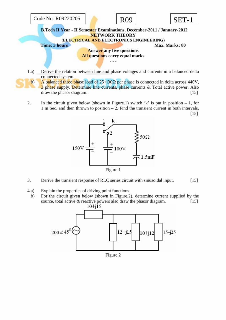
2. In the circuit given below (shown in Figure.1) switch ‘k’ is put in position – 1, for
1 m Sec. and then thrown to position – 2. Find the transient current in both intervals. [15]
Figure.1
3. Derive the transient response of RLC series circuit with sinusoidal input. [15] 4.a) Explain the properties of driving point functions. b) For the circuit given below (shown in Figure.2), determine current supplied by the
source, total active & reactive powers also draw the phasor diagram. [15]
Figure.2
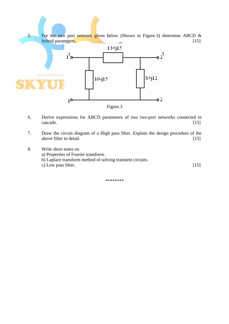
5. For the two port network given below (Shown in Figure.3) determine ABCD &
hybrid parameters. [15]
Figure.3
6. Derive expressions for ABCD parameters of two two-port networks connected in
cascade. [15] 7. Draw the circuit diagram of a High pass filter. Explain the design procedure of the
above filter in detail. [15] 8. Write short notes on a) Properties of Fourier transform. b) Laplace transform method of solving transient circuits. c) Low pass filter. [15]
********

Code No: R09220401 Code No: R09220205 R09R09 SET-2SET-2 B.Tech II Year - II Semester Examinations, December-2011 / January-2012
NETWORK THEORY (ELECTRICAL AND ELECTRONICS ENGINEERING)
Time: 3 hours Max. Marks: 80 Answer any five questions
All questions carry equal marks - - -
1.a) What are the different methods used for measuring power in three phase circuits? b) A balanced the phase load of 30+j40Ω per phase is star connected across 400 V,
50 Hz, 3-phase supply. Determine phase currents and phase voltages. Also draw the phasor diagram. [15]
2. Obtain the expression for i(t) when the switch ‘S’ is closed at t= 0 (shown in
Figure.1). Discuss the three cases of over damped, under damped and critically damped conditions. Sketch the voltage variation across each element. [15]
Figure.1
3. A sinusoidal voltage of 100Sin50t is applied to a series circuit of R = 15Ω and
L = 2.5H at t=0 (shown in Figure.2). By Laplace transform method, determine the current i(t) for all t≥0. Assume zero initial conditions. [15]
Figure.2
4. For the circuit given below (shown in Figure.3) determine the current through each
element, source currents and total power dissipated. [15]

Figure.3
5. For the two port network given below (shown in Figure.4) determine Y and ABCD
parameters. [15]
Figure.4
6. Derive expressions for Impedance parameters of two two-port networks connected in series. [15]
7. Draw the circuit diagram of a Band pass filter. Explain the design procedure of the
above filter in detail. [15] 8. Write short notes on
a) Phase angle spectra. b) Fourier transform properties. c) Driving Point Functions. [15]
********

Code No: R09220205 SET-3R09 B.Tech II Year - II Semester Examinations, December-2011 / January-2012
NETWORK THEORY (ELECTRICAL AND ELECTRONICS ENGINEERING)
Time: 3 hours Max. Marks: 80 Answer any five questions
All questions carry equal marks - - -
1.a) With the help of circuit diagram, explain the procedure of measuring power in three
phase circuits using two watt meters. b) A balanced three load of (15-j20)Ω per phase is delta connected across 220V, 50Hz,
3-phase supply. Calculate total active and reactive power. Also draw the complete phasor diagram. [15]
2. In the circuit shown in Figure.1 the switch is closed on the position – 1 at t=0 there by
applied a D.C. voltage of 150V to series R-L circuit. At t = 500µSec, the switch is moved to position-2 obtain the expression for current i(t) in the both intervals sketch i(t). [15]
Figure.1
3. A sinusoidal voltage of 75Sin30t is applied to a series circuit of R = 20Ω and L =
1.5H at t=0 (shown in Figure.2). By differential equation method, determine the current i(t) for all t≥0. Assume zero initial conditions. [15]
Figure.2
4.a) What is transform impedance & transform circuit? b) For the circuit given below (shown in Figure.3) determine the current in each branch.
Also draw the phasor diagram. [15]

Figure.3
5. For the two port network given below (shown in Figure.4) determine Z and ABCD
parameters. [15]
Figure.4
6. Derive expressions for transmission parameters of two two-port networks connected
in cascade. [15] 7. Design a symmetrical T attenuator to give 2 dB attenuation to have a characteristic
impedance of 150Ω. [15] 8. Write short notes on a) Line and phase angle spectra b) Fourier integrals c) Poles and zeros of Networks Functions. [15]
********

Code No: R09220205 SET-4R09 B.Tech II Year - II Semester Examinations, December-2011 / January-2012
NETWORK THEORY (ELECTRICAL AND ELECTRONICS ENGINEERING)
Time: 3 hours Max. Marks: 80 Answer any five questions
All questions carry equal marks - - -
1.a) Derive the relationship between line and phase voltage and currents in a balanced star
connected system. b) Prove that the power in three phase circuit can be measured using two watt meters. [15] 2. In the circuit given below (shown in Figure.1) switch ‘k’ is put in position – 1, for
1 m Sec and then thrown to position-2. Find the transient current in both intervals. [15]
Figure.1
3. A sinusoidal voltage of 105Sin40t is applied to a series circuit of R = 25Ω and
L = 1.5H at t = 0 (shown in Figure.2), by Laplace transform method. Determine the current i(t) for all t ≥0. Assume zero initial conditions. [15]
Figure.2
4. Determine Impedance and hybrid parameters of the following two port network
(shown in Figure.3). [15]

Figure.3
5.a) For the circuit given below (shown in Figure.4) determine current supplied by source
& power factor.
Figure.4
b) What is the Signature of poles & zeros? [15]
6. Derive expressions for Admittance parameters of two two-port networks connected in
parallel. [15] 7. Design a symmetrical T-attenuation to give 20 dB attenuation and to have
characteristic impedance of 300Ω. [15] 8. Write short notes on a) Fourier transform theorems. b) Exponential form of Fourier series c) Transform impedance & Transform circuits. [15]
********

JNTUWORLD
R09 SET No - 1CODE NO: R09220205
II B.TECH - II SEMESTER EXAMINATIONS, APRIL/MAY, 2011 NETWORK THEORY
(ELECTRICAL AND ELECTRONICS ENGINEERING) Time: 3hours Max. Marks: 75
Answer any FIVE questions All Questions Carry Equal Marks
- - - 1.a) Derive the expression for the power measured and power factor in the two watt meter
method applied for balanced loads. b) A 3-phase 500 V motor operates at a power factor of 0.4 and takes an input power of
30 kW. Two watt meters are employed to measure the input power. Find readings on each instrument. [7+8]
2.a) The circuit shown in the figure 1 has no stored energy. Find the Laplace transform of
current supplied by the battery up on the closure of switch at t = 0. Hence find the initial and final values of the current.
Figure 1
b) Explain the procedure adopted for the evaluation of initial conditions. [8+7] 3.a) Derive expression for the transient response of an R L series circuit excited by
sinusoidal excitation. b) A series R C circuit with R = 100 Ω and C = 25 µF has a sinusoidal excitation
V(t) = 250 Sin 500t. Find the total current assuming that the capacitor is initially uncharged. [7+8]
4.a) Find the transform impedance of the network shown in below figure 2. b) What is a transfer function? Explain the necessary conditions for transfer functions. [8+7]
Figure 2
www.jntuworld.com
www.jntuworld.com
JNTUWORLD
SET No - 1R09CODE NO: R09220205
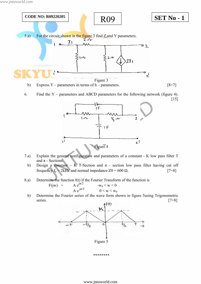
5.a) For the circuit shown in the figure 3 find Z and Y parameters.
Figure 3
b) Express Y – parameters in terms of h – parameters. [8+7] 6. Find the Y – parameters and ABCD parameters for the following network (figure 4). [15]
Figure 4
7.a) Explain the general configuration and parameters of a constant - K low pass filter T
and π - Sections. b) Design a constant – K T-Section and π - section low pass filter having cut off
frequency fc = 2kHz and normal impedance Z0 = 600 Ω. [7+8] 8.a) Determine the function f(t) if the Fourier Transform of the function is
F(jw) = A ejπ/2 -w0 < w < 0 A e-jπ/2 0 < w < w0
b) Determine the Fourier series of the wave form shown in figure 5using Trigonometric series. [7+8]
Figure 5
********
www.jntuworld.com
www.jntuworld.com

JNTUWORLD
R09 SET No - 2CODE NO: R09220205
II B.TECH - II SEMESTER EXAMINATIONS, APRIL/MAY, 2011 NETWORK THEORY
(ELECTRICAL AND ELECTRONICS ENGINEERING) Time: 3hours Max. Marks: 75
Answer any FIVE questions All Questions Carry Equal Marks
- - - 1.a) Derive expression for the power measured in two watt meter method for un balanced
loads. b) The two watt meter readings in a 3 - phase power measurement are 800 W and 400 W.
The latter reading is being obtained after the reversal of current coil. Calculate the total power and power factor of the load. [7+8]
2.a) A current source of the figure 1 shown below supplies at current i ( t ) = 0, 0t ≤ i (t) = t, t > 0. Find (t) 0V
Figure 1
b) Derive the expression for the transient response of RC series circuit excited by a dc voltage source. Use Laplace technique. [8+7]
3.a) Derive the expression for the transient response of an RLC series circuit excited by a
Sinusoidal source. b) A Sinusoidal Voltage of 12 sin 8 t Volts is applied at t = 0 to a RC series of R= 4Ω
and L = 1 H. By Laplace transform method determine the circuit current i (t) for . Assume zero initial condition. [7+8]
0t ≥
4.a) Explain the necessary conditions for driving point functions. b) Find the transform impedance of the following circuit (figure 2). [8+7]
Figure 2
www.jntuworld.com
www.jntuworld.com
JNTUWORLD
SET No - 2R09CODE NO: R09220205
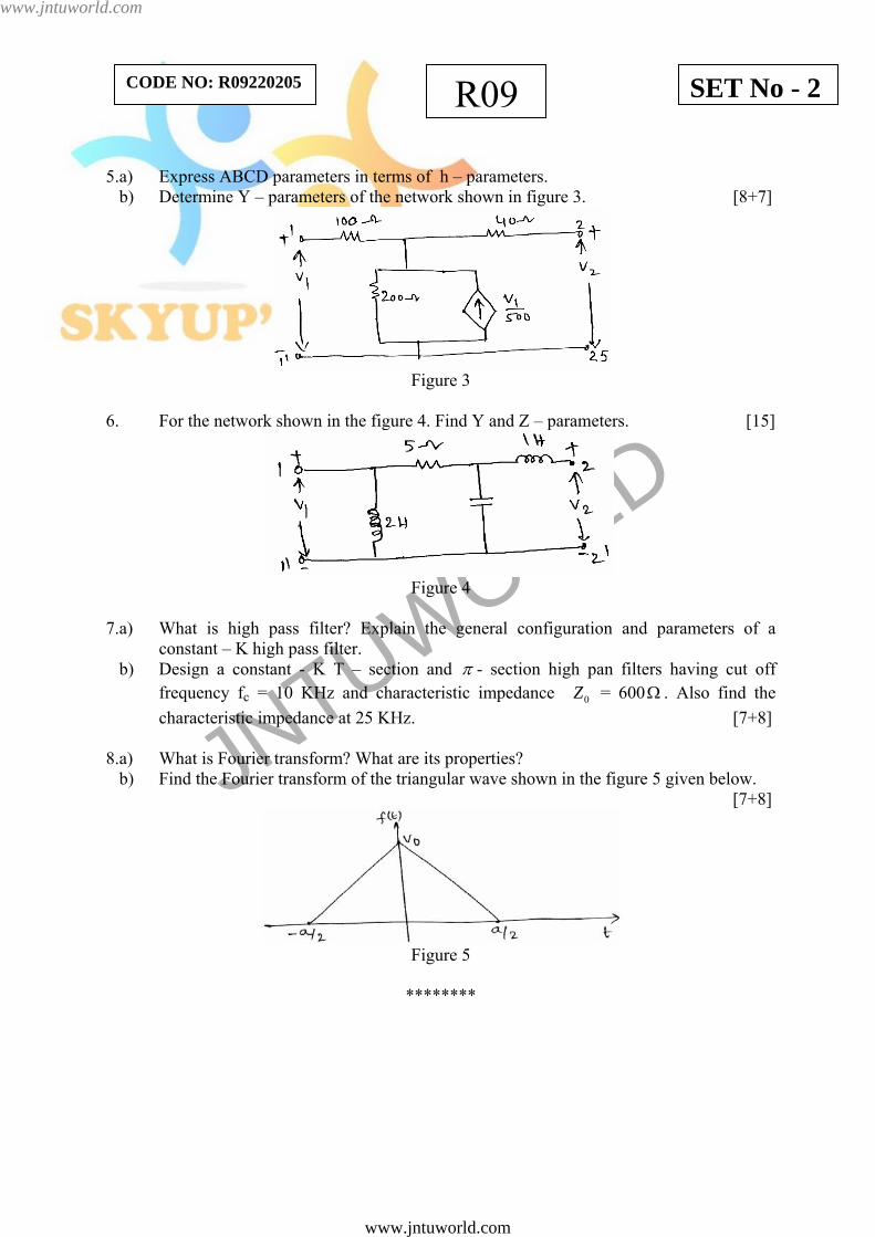
5.a) Express ABCD parameters in terms of h – parameters. b) Determine Y – parameters of the network shown in figure 3. [8+7]
Figure 3
6. For the network shown in the figure 4. Find Y and Z – parameters. [15]
Figure 4
7.a) What is high pass filter? Explain the general configuration and parameters of a
constant – K high pass filter. b) Design a constant - K T – section and π - section high pan filters having cut off
frequency fc = 10 KHz and characteristic impedance 0Z = 600 . Also find the characteristic impedance at 25 KHz. [7+8]
Ω
8.a) What is Fourier transform? What are its properties? b) Find the Fourier transform of the triangular wave shown in the figure 5 given below. [7+8]
Figure 5
********
www.jntuworld.com
www.jntuworld.com
JNTUWORLD
R09 SET No - 3CODE NO: R09220205
II B.TECH - II SEMESTER EXAMINATIONS, APRIL/MAY, 2011 NETWORK THEORY
(ELECTRICAL AND ELECTRONICS ENGINEERING) Time: 3hours Max. Marks: 75
Answer any FIVE questions All Questions Carry Equal Marks
- - - 1.a) Discuss the effect of variation of power factor on the readings of two watt meters used
in 3-phase power measurement. b) Calculate the active and reactive components of the currents in each phase of a star
connected generator supplying at 11 kV to a load of 5 MW at 0.8 pf lagging. What is the value of new output if the total current is same and the pf is raised to 0.85? [7+8]
2.a) Derive the expressions for the transient current of RL series circuit when excited by a
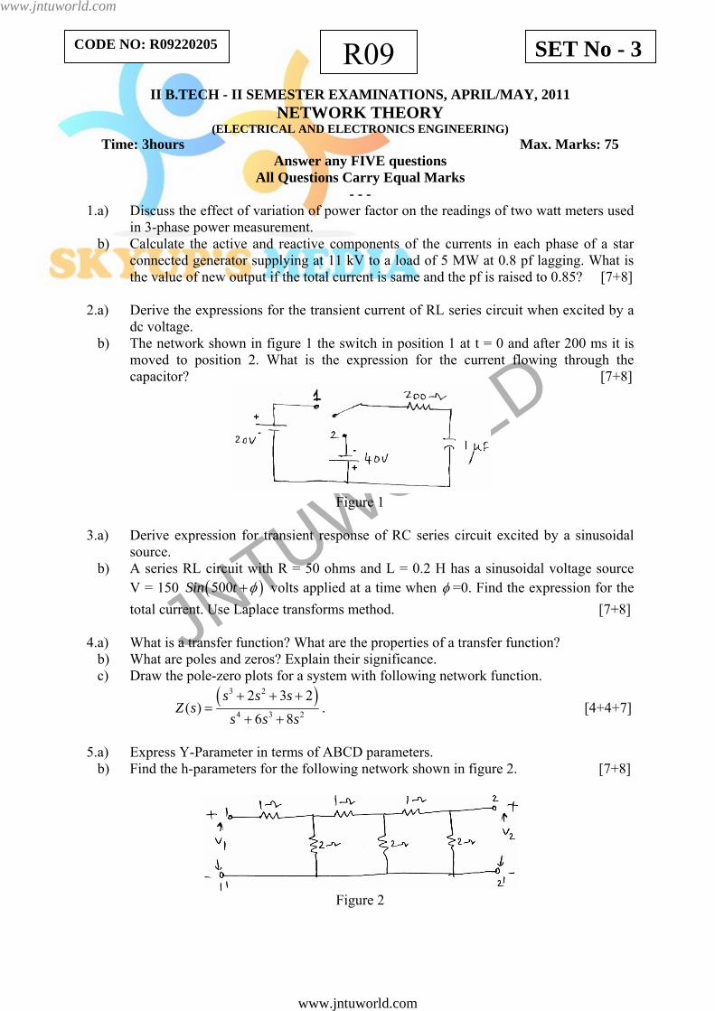
dc voltage. b) The network shown in figure 1 the switch in position 1 at t = 0 and after 200 ms it is
moved to position 2. What is the expression for the current flowing through the capacitor? [7+8]
Figure 1
3.a) Derive expression for transient response of RC series circuit excited by a sinusoidal source. b) A series RL circuit with R = 50 ohms and L = 0.2 H has a sinusoidal voltage source V = 150 (500Sin t )φ+ volts applied at a time when φ =0. Find the expression for the total current. Use Laplace transforms method. [7+8]
4.a) What is a transfer function? What are the properties of a transfer function? b) What are poles and zeros? Explain their significance. c) Draw the pole-zero plots for a system with following network function.
( )3 2
4 3 2
2 3 2( )
6 8s s s
Z ss s s+ + +
=+ +
. [4+4+7]
5.a) Express Y-Parameter in terms of ABCD parameters. b) Find the h-parameters for the following network shown in figure 2. [7+8]
Figure 2
www.jntuworld.com
www.jntuworld.com

JNTUWORLD
SET No - 3R09CODE NO: R09220205 6. For the following network shown in figure 3 determine h-parameters and ABCD
parameters. [15]
Figure 3
7.a) What is an m-derived filter? Explain the general configuration and parameters of m- derived low pass filter for T and Π-Sections.
b) Design an m derived high pass Π-Section filter having a cut off frequency 3250 Hz. The frequency of infinite attenuation may be taken at 2750 Hz. The characteristic impedance is 450Ω. [7+8]
8.a) State and explain Fourier Theorem.
b) The sweep voltage wave form is shown in the figure 4 given below. Find the exponential form of the Fourier series. Draw the frequency and phase spectrums. [7+8]
Figure 4
* * * * *
www.jntuworld.com
www.jntuworld.com
JNTUWORLD
R09 SET No - 4CODE NO: R09220205
II B.TECH - II SEMESTER EXAMINATIONS, APRIL/MAY, 2011 NETWORK THEORY
(ELECTRICAL AND ELECTRONICS ENGINEERING) Time: 3hours Max. Marks: 75
Answer any FIVE questions All Questions Carry Equal Marks
- - - 1.a) Explain the measurement of reactive power in a 3-phase circuit single wattmeter
method. b) A balanced 3-phase star connected load of 200 kW takes a leading current of 150 amps with a line voltage of 1200 V at 60 Hz. What are the circuit constants of the load per phase? [7+8] 2.a) Derive the expression for the transient response in an RLC series circuit excited by a
DC source. b) A constant voltage is applied to a series RL circuit at t = 0. The voltage across the
inductor at t = 3.46 ms is 20 V and 5 V at t = 25 ms. Obtain R if L = 2H. [7+8] 3.a) A series RLC circuit with R = 10 Ω, L = 0.1 H and C = 2µF is excited by a source with v(t) = 200 ( )250 4Cos t Π+ . Determine the complete solution for the current when the
circuit is closed at t = 0. b) Derive the expression for the transient response of RC series circuit excited by a sinusoidal excitation. Use Laplace transform approach. [7+8] 4.a) How can you assess the nature of time domain response from pole-zero plot? Explain. b) Find the transform impedance of the following circuit shown in figure 1. [7+8]
Figure 1
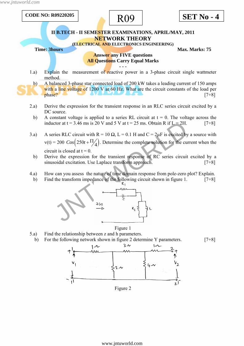
5.a) Find the relationship between z and h parameters. b) For the following network shown in figure 2 determine Y parameters. [7+8]
Figure 2
www.jntuworld.com
www.jntuworld.com

JNTUWORLD
SET No - 4R09CODE NO: R09220205
6. For the following network shown in figure 3 determine Y and Z parameters. [15]
Figure 3
7.a) What is a band pass filter? Explain the general configuration and various parameters of constant-k band pass filters for T and Π-Sections. b) What are the steps involved in design of composite filter? [7+8] 8.a) Find the exponential form of the Fourier Series expansion for the periodic rectangular
pulse train shown in figure 4. Also draw frequency spectrum taking 16
pTT
= .
Figure 4
b) What are the properties of Fourier Transform? [8+7]
* * * * *
www.jntuworld.com
www.jntuworld.com