Embed Size (px)
Citation preview

Electrical and Computer Engineering
12/07/06
DSRC Accident Warning System at
IntersectionRicha Prasad ● Raza Kanjee ● Hui Zhu ● Thai Nguyen
Professor Prishro-NikAdvisor, Assistant Professor, ECE
Professor NiAdvisor, Assistant Professor, CEE
Team Pishro-Nik & Ni

2Electrical and Computer Engineering
12/07/06
Content• Introduction
• The Design
• Deliverables
• System Block Diagram
• MDR Specifications
• Spec 1 – Latency Calculations
• Spec 2 – Transceiver
• Spec 3 – Traffic Light
• Power Specifications
• Product Cost
• PDR I Questions
• Summary
3Electrical and Computer Engineering
12/07/06
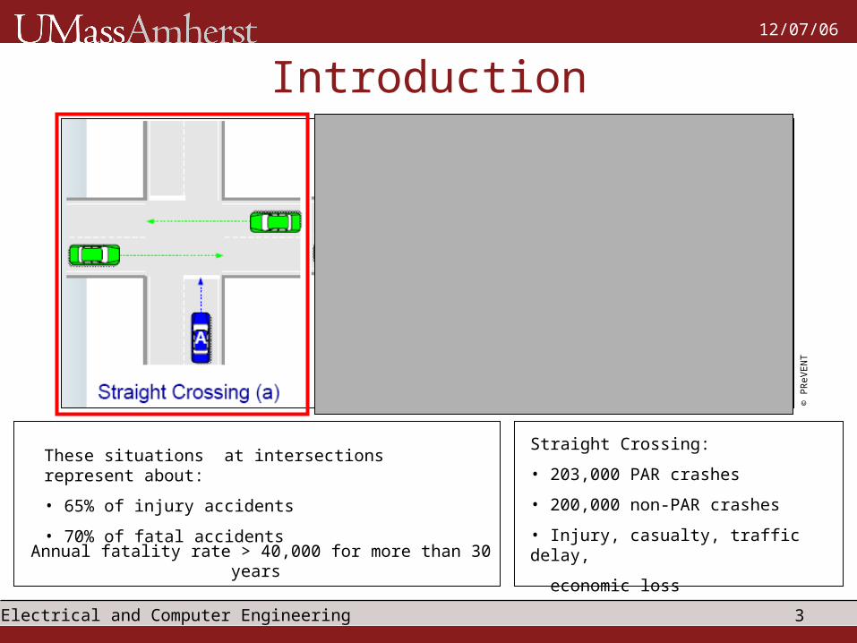
Introduction
These situations at intersections represent about:
• 65% of injury accidents
• 70% of fatal accidents
Annual fatality rate > 40,000 for more than 30 years
© P
ReV
EN
T
Straight Crossing:
• 203,000 PAR crashes
• 200,000 non-PAR crashes
• Injury, casualty, traffic delay,
economic loss

4Electrical and Computer Engineering
12/07/06
The DesignVII DSRC
• Vehicle Infrastructure Integration
Entertainment
Safety
Traffic
Routing
Weather
Tutor • Dedicated Short Range Communication
• 5.9 GHz Frequency Band
• Allocated for VII
• IEEE Standard: 802.11p
Path Suggestion
Speed Suggestion
Pedestrian Warning
Traffic Management
© P
ReV
EN
T
5Electrical and Computer Engineering
12/07/06
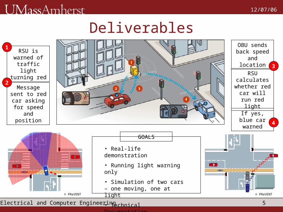
DeliverablesRSU is
warned of traffic light turning red
Message sent to red car asking for speed
and position
OBU sends back speed and location
RSU calculates
whether red car will run
red light
If yes, blue car warned
1
2
3
4
GOALS
• Real-life demonstration
• Running light warning only
• Simulation of two cars – one moving, one at light
• Technical Documentation
© PReVENT © PReVENT

6Electrical and Computer Engineering
12/07/06
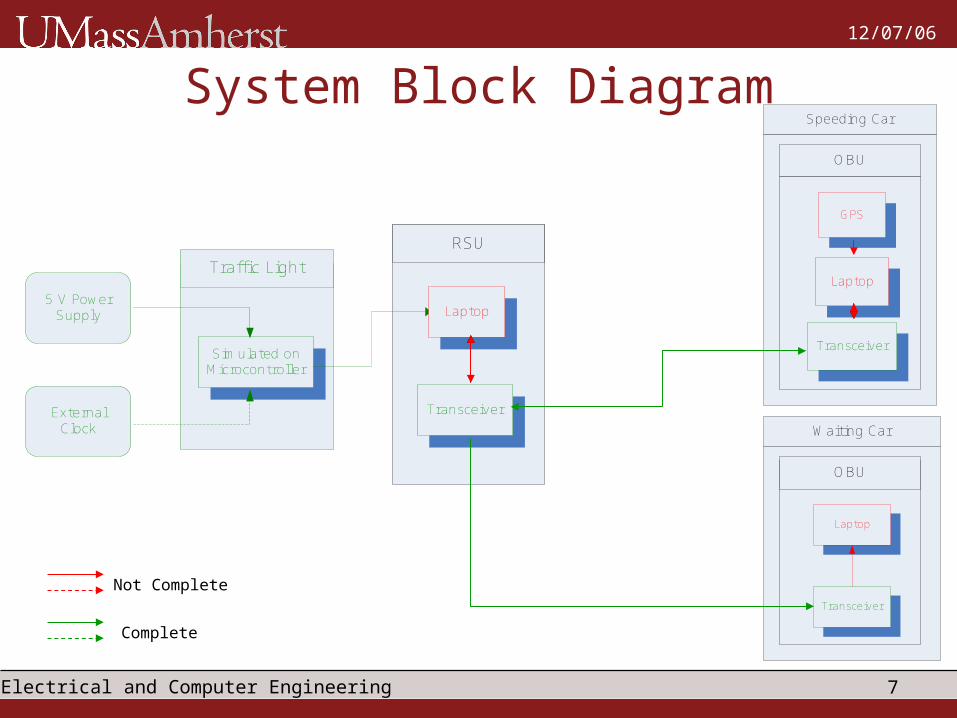
System Block Diagram
Traffic Light
RSU
Speeding Car
Waiting Car
5 V Power Supply
External Clock
Simulated on Microcontroller
OBU
GPS
OBU
Laptop
TransceiverInformation Signal
Control Signal
Power Supply
SpeedLocation
Log dataTransfer
Do Nothing
Calculate if car will run
red light
Traffic light turning red?
No
Yes Alarm signal
Alarm signal
Laptop
Transceiver
Laptop
Transceiver
7Electrical and Computer Engineering
12/07/06
System Block Diagram
Traffic Light
RSU
Speeding Car
Waiting Car
5 V Power Supply
External Clock
Simulated on Microcontroller
OBU
GPS
OBU
Laptop
Transceiver
Laptop
Transceiver
Laptop
Transceiver
Not Complete
Complete

8Electrical and Computer Engineering
12/07/06
MDR SpecificationsAIM
• Changing conditions recognized by laptop
• Display of changing conditions on Bar LEDTraffic Light
• Hardware Simulation of traffic light
• Data communicated = random && != GPS
• Two-way communication between laptopsTransceiver
• Wireless connection between Bridge & AP
• Background for Accident Conditions
• Determination of car running red lightLatency
Calculations
• Distance for Vehicle Warning
9Electrical and Computer Engineering
12/07/06
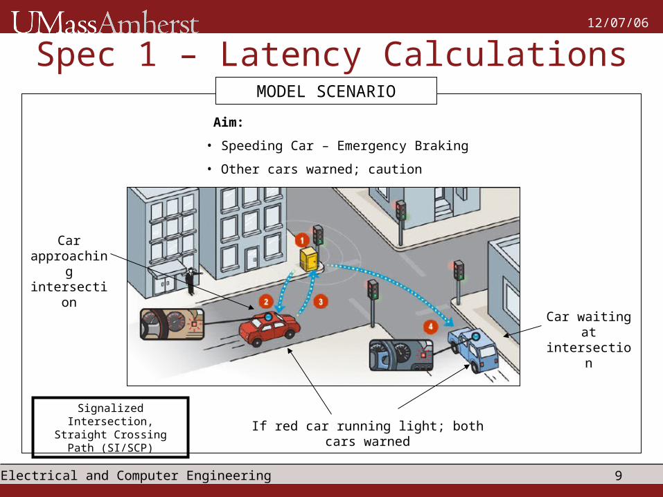
Spec 1 – Latency CalculationsMODEL SCENARIO
Car approaching intersection
Car waiting at intersection
If red car running light; both cars warned
Aim:
• Speeding Car – Emergency Braking
• Other cars warned; caution
Signalized Intersection, Straight Crossing Path
(SI/SCP)

10Electrical and Computer Engineering
12/07/06
Spec 1 - Latency CalculationsBACKGROUND OF ACCIDENTS
0%
2%
4%
6%
8%
10%
12%
14%
16%
18%
0-5 6-10 11-15 16-20 21-25 26-30 31-35 36-40 41-45 46-50 51-55 56+
Snowy or Icy 2%
Wet Pavement 19%
Dry 79% No Adverse Weather
66%
Rain 12% Snow/Sleet 12%
Daylight 72%
Dark, Lighted
22%
Dark, Unlighted
3%
Dawn/Dusk 3%
Travel Velocity (mph)
SI/SC
P C
rash
Occ
urr
ence
SI/SCP Crash Occurrence due to Pavement Condition
SI/SCP Crash Occurrence due to Ambient Weather Condition
SI/SCP Crash Occurrence due to Ambient Light Condition
Driver Inattention
36.4%
Failed to Obey Signal 23.2%
Tried to beat Signal 16.2%
Driver Intoxication
12.9%
Other 5.9%
Vision Obstructed 4.3% Vehicle Defect 1.9%

11Electrical and Computer Engineering
12/07/06
Spec 1 – Latency CalculationsWARNING SYSTEM
Green Light?Start
Amber Light?
Red Light?
Car can clear?
Warning
No Action
No
No
No
No
Yes
Yes
Yes
Yes
Factors
• Travel Speed
• Duration of amber light
• Level of braking
• Driver + machine delays
12Electrical and Computer Engineering
12/07/06
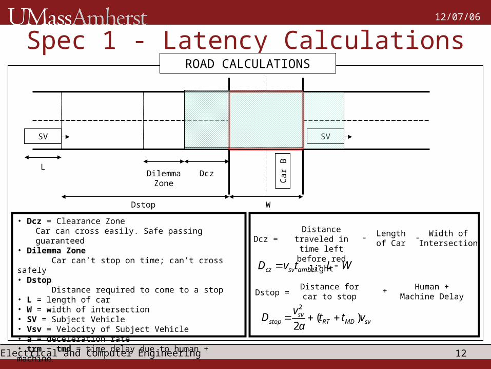
Spec 1 - Latency CalculationsROAD CALCULATIONS
SV
Car
B
SV
DczDilemma Zone
Dstop W
L
• Dcz = Clearance ZoneCar can cross easily. Safe passing guaranteed
• Dilemma Zone Car can’t stop on time; can’t cross safely• Dstop Distance required to come to a stop• L = length of car• W = width of intersection• SV = Subject Vehicle• Vsv = Velocity of Subject Vehicle• a = deceleration rate• trm + tmd = time delay due to human + machine
Distance traveled in time left before
red light
Length of Car
Width of IntersectionDcz = - -
svMDRTsv
stop vtta
vD )(
2
2
WLtvD ambersvcz
Distance for car to stop
Human + Machine DelayDstop = +

13Electrical and Computer Engineering
12/07/06
Spec 1 - Latency CalculationsROAD CALCULATIONS
0
50
100
150
200
250
300
5 10 15 20 25 30 35 40 45 50 55 60 65 70 75 80 85 90 95 100
Dcz30 Dcz25 Dcz20 Dcz15 Dcz10 Dcz5 Speed (kph)
Dcz
(m
)
Dcz at different speeds with different amounts of time left before red light

14Electrical and Computer Engineering
12/07/06
Spec 1 - Latency CalculationsROAD CALCULATIONS
In Dcz?
a = + or 0?
Calculate deceleration for v =0 at stop line
Comfortable range?
Time to reach stop line
Calculate Dstop
Dstop < Dloc
Warning
ts < tg
30s to Red
No Action
ts = time to reach stop line
tg = time for light to turn green
Dloc = distance from stop line
Yes
Yes
Yes
Yes
No
No
Yes
No
No
No

15Electrical and Computer Engineering
12/07/06
Spec 1 - Latency CalculationsSYSTEM LATENCIES
Traffic Light
Laptop
Transceiver
GPS
Laptop
Transceiver
R
S
U
O
B
U
Almost Immediate Almost Immediate
Almost ImmediateAlmost Immediate
• 2400 baud = 19200 bps
• Longitude + Latitude + Speed Info = 12 bytes = 96 bits
• GPS Update = every 0.5s
• Size sent = 192 bps
• Available versus Used = 100:1
• Human + Machine Delay = 2.0s
• Comfortable deceleration = 0 to 3 m/s 2
• Status Messages: > 30s for red light
• Event Messages: < 30s for red light
1. Status Messages: RSU Laptop logs and saves data
2. Event Messages: RSU performs calculations 3. Status Messages: ALL calculations and data saved

16Electrical and Computer Engineering
12/07/06
Spec 2 - TransceiverSPECIFICATIONS
• Airbornedirect Serial Bridge
• RS232 Serial Communication
• 802.11b/g Compliant
• 5 VDC External Supply
CONNECTIVITY
12 VDC
Ethernet
5 VDC
Serial
RSU OBU
Access Point
Bridge
802.11g

17Electrical and Computer Engineering
12/07/06
Spec 2 - TransceiverOUTPUT
OBU
RSU
Video Available on Request!

18Electrical and Computer Engineering
12/07/06
Spec 3 – Traffic LightSET UP
Bar LED Traffic Light
Power is on
Microprocessor programmed with traffic light code
Maxim chip – TTL to RS232 and vice versa
External Clock
JTAG programmer
Indicator of data transfer
Powered by USB
• Green to Warning – 60 s
• Warning to Yellow – 25 s
• Yellow to Red – 5 s
• Green to Red – 90 s
Warning – 30 s

19Electrical and Computer Engineering
12/07/06
Spec 3 – Traffic LightSPECIFICATIONS
SV
Car
B
SV
DczDilemma Zone
Dstop W
L
Dilemma Zone
• Subject Vehicle cannot cross safely before red light
• Subject Vehicle cannot stop safely at stop line
Aim
• Reduce Dilemma Zone
Gazis et. Al:sv
svyDesignDelarDesignAmbe v
LW
a
Vtt
2Posted Speed Limit
tam
ber
5 s
20Electrical and Computer Engineering
12/07/06
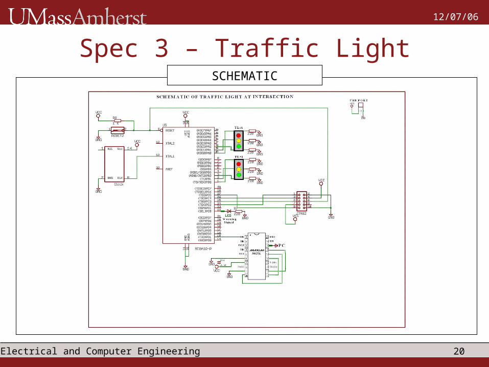
Spec 3 – Traffic LightSCHEMATIC
21Electrical and Computer Engineering
12/07/06
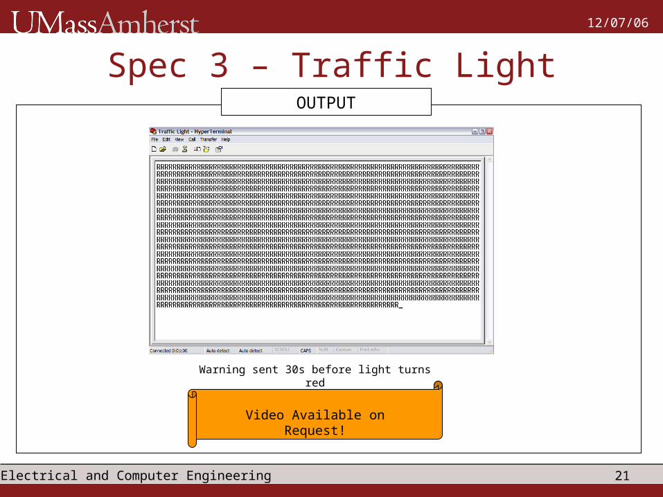
Spec 3 – Traffic LightOUTPUT
Warning sent 30s before light turns red
Video Available on Request!

22Electrical and Computer Engineering
12/07/06
Power Specifications
USB Cable
• USB provides 5 VDC
Powers:
- GPS
- Airbornedirect Bridge
- Traffic Light
• Laptop – self-powered
• Wireless Access Point – 12 VDC
• Solution – 5V to 12V Booster Circuit

23Electrical and Computer Engineering
12/07/06
Product Cost

24Electrical and Computer Engineering
12/07/06
PDR I Questions1. We can adjust the traffic light to prevent collisions. So why do we need the
system?
• System too dynamic, unreliable.
• Predictability of traffic lights lost
2. Elevation on highway. How check if signal received by RSU is from OBU on same highway at which RSU is located?
• GPS provides altitude data
• If RSU altitude != OBU altitude; ignore signal
3. Losing connection with GPS. Solution?
• OBD II Implementation
• DGPS prevents full loss of connection with GPS
4. Urban setting – Accuracy and loss of connection with GPS
• OBD II Implementation
• Video cameras, laser sensors

25Electrical and Computer Engineering
12/07/06
PDR I Questions5. Plan for testing equipment?
• Step 1 – Test in Lab
• Step 2 – Test in field
6. Performance of project under different road and weather conditions?
• Specification 1 – Latency Calculations
• Majority of accidents – normal conditions
7. Theoretical Latency Measurements?
• Specification 1 – Latency Calculations
• Step 3 – Record all data in field
• Step 4 – Debug and test further in lab
8. Vehicle not on road approaching intersection?
• Specify road width
• If collision predicted, should warn regardless

26Electrical and Computer Engineering
12/07/06
Summary
Traffic Light3
Transceiver2
Latency Calculations1
1. Traffic Light
2. Transceiver Communication
3. Latency Calculations
4. a. GPS-Laptop Communication
b. GPS data reception by RSU Laptop
5. RSU Laptop Road Calculation Algorithm
CHECKLIST
MDR SPECIFICATIONS