Embed Size (px)
Citation preview

Electrical and Automation System for Power Generation and Transmission KONTROLMATİK 1
ELECTRICAL AND AUTOMATION SYSTEM
FOR POWER GENERATION AND TRANSMISSION

2 KONTROLMATİK Electrical and Automation System for Power Generation and Transmission Electrical and Automation System for Power Generation and Transmission KONTROLMATİK 3
Enerji üretim ve iletiminde elektrik ve otomasyon sistemleri
One of the most significant necessities of today, electric power has become a value that needs to be monitored carefully from production to consumption. This is primarily due to rate of depletion of fossil fuels and the challenge of global warming the world is facing. Producing electricity at relevant costs, minimizing the impact on the environment during production and delivering power to users at high quality standards with minimum losses are the most critical issues of today.
Older power production technologies did not offer the
benefits of modern technologies currently in use.
Consequently, losses occur with these systems at all
stages from manufacturing to consumption and impact
on the environment is consistently at high levels. On the
other hand, use of „smart“ automation systems and
advanced electrical infrastructures in modern energy
generation and transmission systems can contribute to
improved productivity and energy quality as well as
decreased losses.
Another issue that needs addressing is generating
maximum amount of power with minimum cost.
Optimization in energy, power generation and
transmission systems have become a significant factor
for protecting world‘s natural resources that are
depleted at a fast pace.
Furthermore, information management systems
including management of data from power generation
and transmission systems provide advantages in terms
of preventing faults, quickly eliminating interruptions
and reporting of events.
At Kontrolmatik, we help increase the performance and
productivity of power plants, we provide facilities for
monitoring and security of switchyards and help delivery
of electricity with the lowest possible losses. We achieve
these by means of automation systems and electrical
infrastructures we design and implement specifically to
meet the requirements of our customers operating in the
energy sector.
As one of the leading engineering companies in Turkey,
Kontrolmatik has successfully installed and delivered a
number of projects in a relatively short time. Dynamism
and experience of our team at Kontrolmatik have
challenged and accomplished local and international
projects with great success.
Kontrolmatik builds and installs panels and other
essential hardware for its solutions within its own
capacities; which is the underlying factor behind its
policy of high quality turn-key solutions delivered to
customers.
Kontrolmatik is taking firm steps in becoming a global
brand with its continuous strive in expanding its
products and systems range, employing the most current
technologies.
Having its headquarters in İstanbul, Kontrolmatik offers
a range of projects and services, targeted for its
customer base at home and abroad and intended at
effective use of energy resources. To achieve this, the
quality of data we measure and collect is important. We
have a broad range of testing and measuring equipment
that allows us to collect the most accurate data.
Regularly audited by TÜV, Kontrolmatik meets and
maintains all the requirements of ISO 9001:2000 quality
management system standards and have been the
recipient of ISO 9001:2000 quality system certificate
since 2008.
ABOUT US

4 KONTROLMATİK Electrical and Automation System for Power Generation and Transmission Electrical and Automation System for Power Generation and Transmission KONTROLMATİK 5
Basic engineering and consultancy services for power plantsn Performance evaluation, inspection, review of power
plantsn Electrical single line diagramsn Field layoutn Process flowcharts inspection and reviewn P & I diagrams inspection and reviewn Auction Technical Specifications specifications
inspection and reviewn Performance test procedures for power plants,
inspection and review
Detailed engineering and consultancy services for power plantsn P & ID equipment coding (ISA/KKS) and I & C
inspectionn Electrical load listn MCC control circuit diagramsn Lists and connections of instruments, signals, and
cablesn Instrument assembly documentationn Instrument design and technical spec.sn Function descriptions and logic diagramsn Control panel designn Evaluation of price offer for relevant equipment and
systems
Services we provide for power transmission systemsn Short circuit calculations
- In accordance with IEC60909 standard, computer
aided calculation of maximum and minimum
1 phase, phase-phase and 3 phase short circuit
currents that may occur in busbarsn Calculation of parameters for relays to be used in the
system according to the selectivity which will be used
in the system as a result of short circuit analysisn Drawing short circuit and thermal resistance curves of
transformers on graph papern Drawing short circuit and thermal resistance curves of
MV cables on graph papern Marking minimum short circuit currents to occur in the
system on the graph papern Advanced and detailed reportingn Monitoring tripping times of relays automatically by
simulating the failuresn Selection of MV power cables (inspection with respect
to voltage drop, current carrying, and short circuit)
n Load flow studyn Transient stability studyn Calculation of setting values of motor protection
relaysn Calculation of setting values of generator protection
relaysn Inspection of behavior of the system during operation
of high power motorsn Calculation of transformer power
– Calculation of lighting voltage drop
– Lightning rod (lightning protection) calculations
– Neutral resistance sizing
– Conductor cross section calculation
– Earthing calculations
– Current transformer sizing
– Current–rectifier selection
– Determining relay coordination and relay setting
values
General servicesn Design and analysis of power systems
– Short circuit analysis
– Load flow analysis, load–shedding
– Stability analysis, transition stability, voltage
stability
– Relay coordination, selectivity analysis
– Harmonic analysis, electromagnetic transition
analysis
– Design of power systems
– Grid quality, interconnection works
– Frequency regulation
– Power system stability
– Mathematical modeling of power plantsn Energy SCADA solutionsn Balance of Plant (thermal, natural gas, hydroelectrical)n IEC 61850 and communications applicationsn Applications for industrial processes (DCS, Distributed
Control System)n Power quality analysis and modelingn Power plants TEİAŞ RTU and communication solutionsn Power plants TEİAŞ auxiliary services solutions
(Primary and secondary frequency control, reactive
power control)n Substations; secondary project, relay, panel, and
SCADA solutionsn Electrification solutions for transportation and rail
systemsn Panel solutions
Services we provide for power generation plantsn Design and procurement of control systems
– Architectural design of control systems
– Equipment selection of control systems
– Design and manufacturing of control panels
– Supply of hardware and software panelsn Control systems implementation
– PLC/DCS programming
– Configuration of hardware/software
– HMI/console engineering
– FAT (factory acceptance tests)n Control systems, start–up and commissioning
– SAT (site acceptance tests)
– Commissioning
– Field servicesn Process control engineering
– Functional logic descriptions and logic diagrams
– Control systems specifications
– Instrument design, instrument specifications and
data sheets
– Instrument connection diagrams
– Instrument list, cable list, signal list, alarm list
– Loop cabling diagrams
OUR SERVICES

6 KONTROLMATİK Electrical and Automation System for Power Generation and Transmission Electrical and Automation System for Power Generation and Transmission KONTROLMATİK 7
Electrical andautomation systemin power plants
Monitoring, controlling and reporting of all components of the generation process in power plants are all critical
factors for producing high quality power with lowest possible loss and cost.
By effective use of control systems and electrical infrastructure we install based on the type and capacity of your
power plant, we help you to realize your return on investments within a short period of time.
The two basic infrastructure systems and services we provide for power plants are; automation systems and
electrical systems.
These systems are further described in detail in proceeding pages.
Automation systems
n Balance of plantn Control systemsn PLC systemsn Compact DCS systemsn Advanced DCS systemsn SCADA systemsn Turbine control and protection systems
Electric systems
n Synchronizationn Protection systems (generators, turbines and
transformers)n Excitation systems, automatic voltage regulators
(AVR)n Static starter systemn Measurement

8 KONTROLMATİK Electrical and Automation System for Power Generation and Transmission Electrical and Automation System for Power Generation and Transmission KONTROLMATİK 9
IEC
61
85
0
Mod
bus
Mod
uleb
us
PR
OFI
BU
S /
Foun
dati
on F
ield
bus
/ M
odul
ebus
PR
OFI
BU
S /
PR
OFI
NET
/ M
odul
ebus
/ D
evic
eNet
SafetyProcess Instrumentation Devices PLC and DCS ConnectionsProcess ElectrificationPower Automation
Facility Network
Main System Servers
Field Network
Protection and Control LED
System Network Panel 800Workstation
Wireless HART Gateway AC800M
High Integrity Controller
AC800MController
Motor Controller
Variable Speed Control Drivers
Medium Voltage Switchboards
S900/IO
S800/IO Fire and Gas
Closing
S800, S100...
Wireless HART
Advant, MOD, Harmony...
AUTOMATION SYSTEMS INPOWER PLANTS
Contributions of automation systems to power plants
n Opportunity to access all control parameters from
any point in the systemn Managing and monitoring the entire system from a
single control platformn Rapid command issuingn Integration of electric infrastructure and automation
systemsn Prior determination and prevention of unexpected
faults and reduction of maintenance timen Secure data acquisition and fast data flow
Automation and control systems enable efficient and safe operation of power plants by minimizing the risks. Monitoring and reporting ensure the opportunity to access all control points from any given point in the system as well as flexibility, speed and minimized faults. Kontrolmatik maximizes automation through ”Balance of Plant“ integration, control systems and turbine control systems specifically designed for your facility.
System architecture

10 KONTROLMATİK Electrical and Automation System for Power Generation and Transmission Electrical and Automation System for Power Generation and Transmission KONTROLMATİK 11
Controller
Servers
PROFINET Field Bus Network
Workstations
Control Network
Low Voltage Switchboards
Medium Voltage Switchgears
Power Transformer
Web HMI
IEC 61850
GIS
AIS
HV
Excitation Control
Field Bus Structure
Instrumentation Devices
Valve
Low Voltage Products
Remote ConnectionsDriver
Proxy for Profibus and other busses
Power Distribution Process Electrification Process Control
BALANCE OF PLANT
Independent from the type of your power plant, our
experience and engineering know-how allows us to
provide ”Balance of Plant“ integration specific to your
installations and turn-key system integration.
Balance of Plant includes systems, components and
structures in a power plant other than the main
generation system and heat recovery systems (e.g. gas
turbines, steam turbines...). BOP aims to combine various
independent control systems on a single platform.
Integration of these systems in an optimum way, ability
to share data among systems and the flexibility
introduced by this system are important parameters
leading to the efficiency and productivity of a power
plant.
Services we provide within the Balance of Plant packagen Modulation controln Sequence controln Boiler burning controln Feed water pump controln Boiler safety supervisionn Data acquisitionn Electrical system controln “Balance of Plant” equipment control
n Stack gas desulphurization controln Turbine controln Turbine supervision instrumentation devicesn Combined Cycle controln Emergency shutdownn Data transfer to ERP systemn Boiler optimizationn System efficiency map

12 KONTROLMATİK Electrical and Automation System for Power Generation and Transmission Electrical and Automation System for Power Generation and Transmission KONTROLMATİK 13
BALANCE OF PLANT
MainSteamValves
Turbine Auxiliaries
Building Services
Generator and Auxiliary
Turbine and Auxiliary
Boiler
BoPE
Environmental Control Systems
Main Plant Auxiliary Systems
Electricity
Water
Sewage
Site Facilitiesduring Construction
Main Fuel• Unloading• Storage• Preparation• Transfer
Startup Fuel• Unloading• Storage• Transfer
Fly Ash• Transfer• Storage• Loading
HP Feed Heating
HV Switchyard
Start up Diesel
Water Chemistry
CW Chemistry
AirEvacuation
Condenser
FireFighting
Sewage Plant
WastewaterTreatment
Discharge
CoolingTower
PotableWater
Mobile Equipment
TechnicalBuildings • Boiler Building
• Turbine Building• Electrical Building• Auxiliary Technical Buildings
• Administration Building• Canteen / Social Building• Workshop• Warehouse• Gate House• Fence
Ammonia• Unloading• Storage• Transfer
Sorbent• Unloading• Storage• Preparation• Transfer
Gypsum• Preparation• Transfer• Storage• Loading
Bottom Ash• Transfer• Storage
Silos& Mills
AuxiliaryBoierBoiler
Burner Pressure Firing Parts
NonTechnicalBuildings
HVAC
Boier C&I
BOP / Plant C&I
Lighting
Lightning
FD Fan
SCR /De-NOx
ESP
FGD
Stack
PA Fan
Communication / IT
Plant DCS & Interfaces
Generator C&I / AVR / CTs / VTs
IDFan
Electrical Systems
MV / LV / DC
Step up TransformerGenerator
Auxiliaries
LP Feed Heating
By pass
CPP
HP Pipework & Valves
By pass
GenHPT LPT
Water Treatment
CW Mech Cleaning
ST C&I

14 KONTROLMATİK Electrical and Automation System for Power Generation and Transmission Electrical and Automation System for Power Generation and Transmission KONTROLMATİK 15
Advanced DCS Systems
Advanced DCS systems are used for accessing multiple
applications and multiple data from any workstation
located at any point at the power plant. ABB System
800xA advanced DCS systems increases productivity as
well as decreasing risks and costs.
Integrated engineering infrastructure of the System
800xA minimizes complexities from planning to
configuration and from library management to
commissioning, and offers savings by supporting
lifespan of automation projects. Compliant with IEC
61508 and IEC61511, System 800xA provides security
for the entire system and minimizes the risk ratio.
Powerful reporting feature enables reporting by
processing any process related information. The
advanced planning feature of System 800xA allows a
multitude of different requirements for increasing
production, to be identified beforehand. Also,
continuously monitoring the state of equipment in a
power plant with System 800xA allows for preventive
maintenance which is important to achieve investment
optimization.
Advantages offered by System 800xA in energy productionn A platform that can meet future process and
electrical systems requirementsn Capable of meeting IEC 61850 requirementsn User-friendly user interfacen Ability to access from any point outside the facilityn Quick fault analysis capabilityn Outstanding engineering skills and qualityn Low budget operation and managementn Simple system architecturen Unique technology and integration with existing
systems
CONTROL SYSTEMS
PLC Systems
PLC offers maximum speed and efficiency in production
processes and is an ideal solution for a multitude of
automation needs; from simple to complex that require
high performance, low cost and flexibility. ABB‘s AC500
automation platform for PLC applications is capable of
meeting these ever increasing customer requirements.
With its scalable architecture, AC500 secures your
investment. Managing more than one field bus with a
single control system, user-friendly structure, easy
configuration and ample communication possibilities are
other significant advantages provided by AC500 PLC to
our customers.
Compact DCS Systems
Compact and scalable DCS systems -in addition to
providing powerful automation functions- present low
cost advantage for hardware and software. Ensuring
minimum engineering and maximum automation
facilities, ABB Freelance compact DCS systems have open
and modern system architecture. With its distributed
architecture installed at the field by controllers, it can
effectively reduce cabling costs. Freelance requires single
software for application engineering, commissioning and
fault finding and therefore can be fully integrated into
field bus management control system. Visual components
pre- engineered for operators are one of many
advantages to users.
With its ability to work on standard computer hardware, in
addition to control systems such as DCS, PLC as well as
capability to convert all control parameters into visual
control tools, SCADA software makes it possible to expand
the system to meet changes in future requirements.
Based on open protocol, SCADA is hardware and
manufacturer independent and therefore capable of
expanding to meet future requirements. It contributes to
facilitating reporting and detailed analysis, minimizing
faults, evaluation and improvement on energy efficiency
and system performance.

16 KONTROLMATİK Electrical and Automation System for Power Generation and Transmission Electrical and Automation System for Power Generation and Transmission KONTROLMATİK 17
SCADA SYSTEMS
SCADA (Supervisory Control and Data Acquisition)
system basically consists of human-machine interfaces
(HMI), host and client computer systems, remote
terminal units (RTU), DCS and PLCs, various
communication structures, and different instruments.
HMI is the interface that provides process data to the
operator and therefore allowing the operator to monitor
and control the process. RTU is the unit that provides
connection with sensors in the process, converts sensor
signals into digital signals and sends these signals
upstream to the system. PLC is a configurable and
flexible field device that performs similar functions
locally.
Created as a visual control platform intended for all
supervision, control and monitoring, SCADA can be
present on one or more networks together with sub-
systems mentioned above. This structure allows SCADA
quick and easy access to process data and helps taking
precaution against potential faults.
The entire control architecture covering a number of
systems can be transferred to SCADA over DCSs; such as
turbine and boiler control, cooling systems control,
monitoring coal transportation line, switchyard and MCC
panels, controlling condensers and analyzing gases in a
power plant etc.
In addition to control functions, SCADA offers many
facilities such as monitoring events and alarms,
examining and reporting information retrospectively,
providing information to remote operators via GSM
networks. Production report drafts required by electric
utilities companies can be prepared beforehand with
reporting function and automatically created at desired
intervals (daily, weekly, monthly, etc.). Also, “predictive
maintenance” can be made by monitoring operation
times and alarms of actuators such as breakers, engines,
pumps, valves located in the field. In this way, faults
which may occur can be estimated, and down times may
be shortened. With Thin Clients or Web Clients, state of
the system can also be monitored from any remote point
outside of the plant.

Electrical and Automation System for Power Generation and Transmission KONTROLMATİK 19
TURBINE CONTROL AND PROTECTION SYSTEMS
Turbines are at the heart of the electric generation
process and play an active role for converting
mechanical energy into electric energy. Turbines can be
classified as steam, gas, hydro and wind turbines
according to the energy resources they require.
Parameters that are controlled in a turbine control
system may be adapted based on the type of energy
resource. As an example, for the purpose of continuous
and quality energy production in thermal power plants,
it is necessary to control and monitor different
parameters such as water amount and water circulation,
control of feed-water, boiler water temperature, amount
of fuel, pressure, igniter control system, water cooling
system, all the way from burning fuel stage to obtaining
steam and turning turbines.
Turbines can be controlled with PLCs or dedicated
control devices. These systems perform critical closed
closed-loop algorithms such as speed and load control.
Apart from general SCADA interface for controlling and
monitoring, alarm and reporting functions can be
provided with a local and dedicated interface. Data
obtained from the site can be transferred into
SCADA system.
Benefitsn Low lifespan costn Optimized operationn Excellent reliabilityn Increased turbine lifespan via sensitive controlsn Short commissioning timen Decreases in fault costs and repair timesn Fully automated operation eliminating operator
errorsn Quick access to information
For Turbine Control Systems, we use ABB AC800M and
AC870P solutions and Woodward turbine control
solutions.
Turbine protection systems and valve positioning
products are additional components supplementing the
system. Speed, the most critical parameter for rotating
parts, is continuously monitored. Protection systems
are connected to other field devices such as speed
measurement devices and servo valves in turbines.
These provide over speed protection and valve
positioning controls independent from main control.
Turbines are protected and their lifespan is extended
by monitoring many critical parameters such as speed,
oil pressure, temperature, etc. As a result, a quicker,
more flexible, functionally enriched turbine control
system is obtained.

20 KONTROLMATİK Electrical and Automation System for Power Generation and Transmission Electrical and Automation System for Power Generation and Transmission KONTROLMATİK 21
ELECTRIC SYSTEMS IN POWER PLANTS
Facilities need qualified and trained human power, large investment expenses and technologies in order to meet the increasing demand for energy. At this point, automation and smart electric infrastructure is now an indispensable characteristics.
Generator synchronization systems are devices for
providing network and generator safety and security that
are generally used in power generation facilities,
industrial facilities such as cogeneration facilities,
marine industry, hospitals, shopping centers and hotels.
The main purpose of using generators is to minimize
power interruption time and keep continuous power
where connection is available.
The main function of generator synchronization systems
is to transfer energy from the network to the generator
or in reverse case to ensure transition of supplied energy
with synchronized amplitude, phase angle and frequency.
Otherwise overloading can occur at the network or
generator, irregularities may occur at the network,
breakers may open or generators may be damaged.
The main purpose of performing the synchronization
process is to automatically or manually ensure network
and generator security.
During synchronization process, in case a fault occurs on
one of the serially connected channels in a ”dual
channel“ application, the other channel is also blocked.
This configuration increases security. In applications
with “back-up”, in case of any fault anyone of the parallel
connected devices, the other one overtakes the function
and ensure its continuous operation.
SYNCHROTACT product range from ABB is a device
preventing switching in asynchronous mode where there
is significant difference between voltage and phase
angles. Prior to connecting these systems,
SYNCHROTACT brings voltage and speed of generator to
automatically adjusted tolerance interval taking into
account voltage, frequency, phase angle and breaker
switching time. Digital dual channel and redundant
synchronization systems provide high level of reliability.
SYNCHRONIZATION
Kontrolmatik installs turn key excitation systems,
generator protection systems, synchronization systems,
energy invoicing/automated meter reading systems.
Furthermore, as additional services we implement
various applications such as primary and secondary
frequency control systems, reactive power control
systems.
Main applications n Synchronizationn Protection systems
– Generator
– Turbine
– Transformern Excitation systems, automatic voltage regulators
(AVR)n Static starter systemn Measurementn Network connection and power qualityn MCC panel systems PROTECTION SYSTEMS
In a power plant, generators and transformers are units
that are the most likely to have faults and thus they
should be protected in the best manner. Generator
protection includes transformers and auxiliary
transformers in addition the generator itself. In principle
the generator protection includes determining faults and
irregular states within the shortest possible time and
minimizing damages that may occur.
Regardless of the generator type, we provide the most
efficient electric infrastructure as well as secure and
economic systems integration by establishing the criteria
in which a generator can work securely and efficiently.
We use ABB protection units which have modular
hardware, have flexible structure, and utilize
microprocessor based technology. Protection functions
can be selected taking suitable redundancy into account.
This enables reliable, secure and economic functioning of
the generators.
Relion product range designed by ABB for generator
protection provides wide range of products for
protection, control, measurement, and supervision of
generators, transformers, and power lines. Relion product
range meets the requirements of IEC 61850 standard.
The 24 analog inputs of devices that we use ensures
main and redundant protection with a single product.
Alternatively, protection of additional elements such as
transformers can be included to the protection scope of
generators. In addition to cost saving advantage, using
less products reduces the amount of installation and
maintenance work.
These devices offer injection based 100% protection of
stator and earthing faults and 3rd degree harmonic
based 100% protection of stator and earthing faults.
Secure operation is ensured even in low loads.

22 KONTROLMATİK Electrical and Automation System for Power Generation and Transmission Electrical and Automation System for Power Generation and Transmission KONTROLMATİK 23
EXCITATION SYSTEMS
Excitation systems have significant effects on dynamic
performance of generators. Quality of generator voltage
and reactive power, as well as quality of energy
distributed to all electric end users are all determined by
excitation systems.
There are various excitation systems:n Brushless excitation systemsn Rotary excitation machinery and automatic voltage
regulator (AVR)n Static excitation systems (SES) feeding rotors
directly over brushes with thyristor bridge.
The main function of excitation system is to provide
variable DC current having short-period excess load
capacity, control output voltage having proper accuracy,
guarantee stable operation, communicate with power
plant control system and ensure operation of generator
within operating limits.
In systems installed by Kontrolmatik, we use ABB‘s
UNITROL series microprocessor based voltage regulators
with rotary excitation and static excitation systems for
controlling of any type of synchronous machinery (motor
and generator).
UNITROL® includes automatic voltage regulators (AVRs)
and static excitation systems (SESs) that can be used in
any size synchronous generator and motor.
Advantagesn Customer-oriented standardizationn System solutions tailored to customer needsn Compliant with ISO 9001/ISO 14001 quality
management systemsn Worldwide commissioning and maintenance servicesn Quick commissioning and maintenance time with
user friendly software tool
STATIC STARTER SYSTEM (FOR GAS TURBINES)
MEASUREMENT
In power plants, measurement equipment with high level
of sensitivity determines how much energy is supplied
to customers from the production field. Measured values
are current, voltage, active and reactive power. These
values are used for pricing energy consumed and
obtaining statistical data.
Gas turbines need boosting for reaching ignition
point (60% of nominal speed). For gas turbines over
40MW, this can be achieved with two different methods.
n Pony motor with gears on main shaftn Static frequency converter (SFC) that directly
connects to generator terminals and enables
operation of the generator as an electric motor at the
beginning of the phase.
Static starter enables acceleration of the generator
smoothly without any vibration or voltage drop. Also, it
helps deceleration of the generator smoothly. A single
SFC can operate several generators connected in-line.
24 KONTROLMATİK Electrical and Automation System for Power Generation and Transmission Electrical and Automation System for Power Generation and Transmission KONTROLMATİK 25
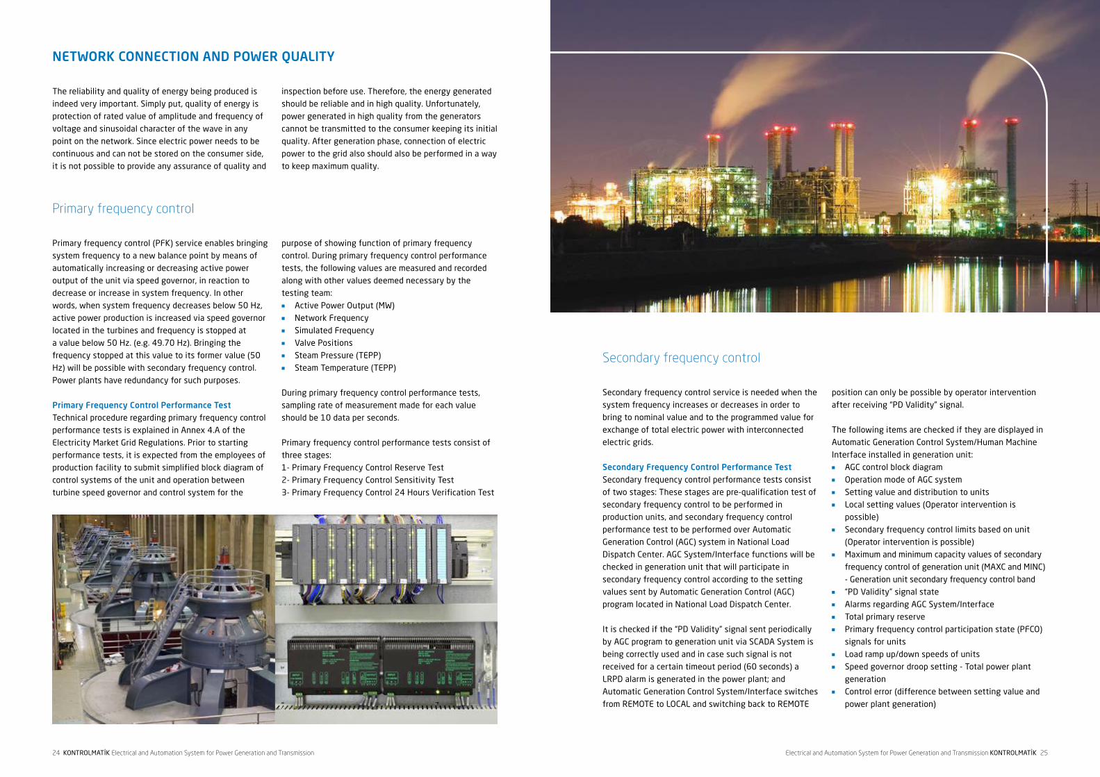
Secondary frequency control
Secondary frequency control service is needed when the
system frequency increases or decreases in order to
bring to nominal value and to the programmed value for
exchange of total electric power with interconnected
electric grids.
Secondary Frequency Control Performance TestSecondary frequency control performance tests consist
of two stages: These stages are pre-qualification test of
secondary frequency control to be performed in
production units, and secondary frequency control
performance test to be performed over Automatic
Generation Control (AGC) system in National Load
Dispatch Center. AGC System/Interface functions will be
checked in generation unit that will participate in
secondary frequency control according to the setting
values sent by Automatic Generation Control (AGC)
program located in National Load Dispatch Center.
It is checked if the “PD Validity” signal sent periodically
by AGC program to generation unit via SCADA System is
being correctly used and in case such signal is not
received for a certain timeout period (60 seconds) a
LRPD alarm is generated in the power plant; and
Automatic Generation Control System/Interface switches
from REMOTE to LOCAL and switching back to REMOTE
position can only be possible by operator intervention
after receiving “PD Validity” signal.
The following items are checked if they are displayed in
Automatic Generation Control System/Human Machine
Interface installed in generation unit:n AGC control block diagramn Operation mode of AGC systemn Setting value and distribution to unitsn Local setting values (Operator intervention is
possible)n Secondary frequency control limits based on unit
(Operator intervention is possible)n Maximum and minimum capacity values of secondary
frequency control of generation unit (MAXC and MINC)
- Generation unit secondary frequency control bandn “PD Validity” signal staten Alarms regarding AGC System/Interfacen Total primary reserven Primary frequency control participation state (PFCO)
signals for unitsn Load ramp up/down speeds of unitsn Speed governor droop setting - Total power plant
generationn Control error (difference between setting value and
power plant generation)
NETWORK CONNECTION AND POWER QUALITY
The reliability and quality of energy being produced is
indeed very important. Simply put, quality of energy is
protection of rated value of amplitude and frequency of
voltage and sinusoidal character of the wave in any
point on the network. Since electric power needs to be
continuous and can not be stored on the consumer side,
it is not possible to provide any assurance of quality and
inspection before use. Therefore, the energy generated
should be reliable and in high quality. Unfortunately,
power generated in high quality from the generators
cannot be transmitted to the consumer keeping its initial
quality. After generation phase, connection of electric
power to the grid also should also be performed in a way
to keep maximum quality.
Primary frequency control
Primary frequency control (PFK) service enables bringing
system frequency to a new balance point by means of
automatically increasing or decreasing active power
output of the unit via speed governor, in reaction to
decrease or increase in system frequency. In other
words, when system frequency decreases below 50 Hz,
active power production is increased via speed governor
located in the turbines and frequency is stopped at
a value below 50 Hz. (e.g. 49.70 Hz). Bringing the
frequency stopped at this value to its former value (50
Hz) will be possible with secondary frequency control.
Power plants have redundancy for such purposes.
Primary Frequency Control Performance TestTechnical procedure regarding primary frequency control
performance tests is explained in Annex 4.A of the
Electricity Market Grid Regulations. Prior to starting
performance tests, it is expected from the employees of
production facility to submit simplified block diagram of
control systems of the unit and operation between
turbine speed governor and control system for the
purpose of showing function of primary frequency
control. During primary frequency control performance
tests, the following values are measured and recorded
along with other values deemed necessary by the
testing team: n Active Power Output (MW)n Network Frequencyn Simulated Frequencyn Valve Positionsn Steam Pressure (TEPP)n Steam Temperature (TEPP)
During primary frequency control performance tests,
sampling rate of measurement made for each value
should be 10 data per seconds.
Primary frequency control performance tests consist of
three stages:
1- Primary Frequency Control Reserve Test
2- Primary Frequency Control Sensitivity Test
3- Primary Frequency Control 24 Hours Verification Test

26 KONTROLMATİK Electrical and Automation System for Power Generation and Transmission Electrical and Automation System for Power Generation and Transmission KONTROLMATİK 27
Reactive power control
Reactive power is required for operation of all devices
that need the effect of magnetic field. Reactive energy
is needed for all devices (e.g. electric motors etc.)
particularly for transformers operating with magnetic
field. However, transferring reactive energy to energy
transmission lines by producing in generation facilities
causes limitation on active power that a line can carry,
and consequently decrease on the line capacity due to
the reason that reactive energy occupies space just as
active energy on transmission lines do. Consequently,
reactive power factor should be kept at levels
determined by regulations.
Reactive Power Control and Synchronous Condenser Performance TestOperation in over-excitation: Means reactive power is
delivered to the system by the generator.
Operation in under-excitation: Means reactive power is
drawn from the system by the generator.
Power quality analysis
Electricity produced at the plant sustains losses and
quality is compromised until delivered to the consumer.
Irregular use of transformers and cables from generation
facilities to the consumer as well as use of illegal
connections to the network inevitably affect quality and
dependability. Therefore, it is very important to ensure
top-quality electricity distributed from the power plants.
Quality of power in simple terms is protection of rated
value of amplitude and frequency of voltage and
sinusoidal character of wave in any point on the
network. Fluctuations in voltage amplitude, power
interruptions, changes like pulses, harmonics, frequency
changes, flicker, three-phase imbalances are the primary
known reasons for power quality losses.
Loads that take non-sinusoidal currents from the
network cause severe harmonic pollution in transmission
and distribution systems and creates line voltage drops
causing disturbance of voltage waveform. Potentially
problematic points should be prevented during grid
design or points presenting danger should be identified
by making risk estimations.
In order to create solutions to increase the quality of
energy generated, the reasons for lack of quality should
be identified, the occurrence times should be
determined and this data should be used to create
classifications. By measuring power quality, different
parameters such as voltage and current changes can be
recorded and necessary precautions can be prepared
based on the results of such measurements; consistency
of the system can be ensured, and great commercial
benefits can be obtained by preventing non-scheduled
power cuts. Continuously monitoring the network
enables obtaining necessary data required for statistical
analysis of problems seen in power systems. This will
allow determining the precautions for future.
Compliant standardsn IEC 61000-4-30: Power quality measurement
methods, Class An IEC EN 61000-4-7: Harmonic measurement manualn IEC EN 61000-4-15: Flickermetern EN 50160: Voltage Characteristics of Electricity
Supplied by Public Distribution Systems
Features of the softwaren FFT analysisn Vectorscope, oscilloscopen Power and energy monitoringn Voltage monitoring with EN 50160 Flickermetern Symmetrical component analyzer for 3 phase
systemsn Power network impedance analyzern Semi periodical RMS monitoringn Transitive log device and fault log devicen Voltage telegram and alarmsn Digital inputs
In addition to records captured in power plants during
generation unit secondary frequency control tests, the
following values will be recorded from SCADA system by
TEİAŞ National Load Dispatch Center:
n Setting values sent by National Load Dispatch Centern System frequency valuen Active power generation of power plant/block/unitn Active power generation of units (when necessary)
Maximum reaction time should be 30 seconds in order to
start changing power output of generation unit which
provides secondary frequency control service, and it
should reach required generation level according to the
loading speed determined as result of tests. Loading
speed of units providing secondary frequency control
service should be as follows depending on the fuel type:
n At least 6% of nominal power per minute for diesel
oil, fuel oil, and natural gas generation facilitiesn Between 1.5% and 2.5% of nominal power for
hydroelectric generation facilities with reservoirn Between 2% and 4% of nominal power for generation
facilities using hard coal as a fueln Between 1% and 2% of nominal power for generation
facilities using lignite as a fuel

28 KONTROLMATİK Electrical and Automation System for Power Generation and Transmission Electrical and Automation System for Power Generation and Transmission KONTROLMATİK 29
MCC panels are panel systems where engine main
feeding units and control devices are located.
Control devices such as PLC and DCS and other devices
required for SCADA and communications infrastructure
are found in control section of the MCC panel.
Panels are important components of the system and are
supplementary in projects we implement. For all systems
that we install, Kontrolmatik can produce type-tested
distribution panels including form 4-B, MCC Panels
(Motor Control Panels) and Motor Driver Panels up to 400
KW within our own capacities.
In accordance with IEC 60439-1 standard, we separate
functional sections from each other within the panels
with form applied LV Distribution and MCC panels, in
order to increase the safety of personnel and facilities.
For custom applications, we can produce panel
applications with IP66 protection class as well as UL50
certified panel applications in accordance with American
standards. We use RAL7035 and RAL7032 colors as
standard.
We use custom-designed bus systems for power
distribution systems and especially MCC panels.
MCC PANEL SOLUTIONS
30 KONTROLMATİK Electrical and Automation System for Power Generation and Transmission Electrical and Automation System for Power Generation and Transmission KONTROLMATİK 31
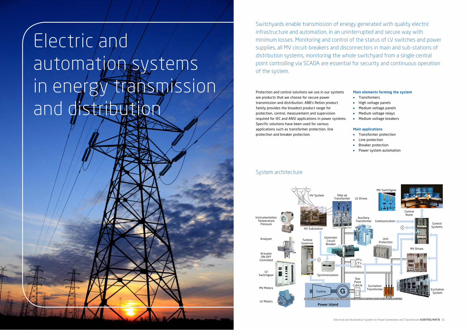
Electric andautomation systems in energy transmission and distribution
Switchyards enable transmission of energy generated with quality electric infrastructure and automation, in an uninterrupted and secure way with minimum losses. Monitoring and control of the status of LV switches and power supplies, all MV circuit-breakers and disconnectors in main and sub-stations of distribution systems, monitoring the whole switchyard from a single central point controlling via SCADA are essential for security and continuous operation of the system.
Protection and control solutions we use in our systems
are products that we choose for secure power
transmission and distribution. ABB‘s Relion product
family provides the broadest product range for
protection, control, measurement and supervision
required for IEC and ANSI applications in power systems.
Specific solutions have been used for various
applications such as transformer protection, line
protection and breaker protection.
Main elements forming the systemn Transformersn High voltage panels n Medium voltage panels n Medium voltage relays n Medium voltage breakers
Main applicationsn Transformer protection n Line protection n Breaker protectionn Power system automation
System architecture
1
1

32 KONTROLMATİK Electrical and Automation System for Power Generation and Transmission Electrical and Automation System for Power Generation and Transmission KONTROLMATİK 33
Substation automation includes power control systems
in substations, signal measurement, protection as well
as remote management devices and functions intended
for transferring field data into central station. In order to
perform control operations in a reliable way, state of the
switchyard should be continuously monitored. This
means reliable products and secure communication with
control center are essential.
The technological advancements allow the use of
distributed control systems in switchyards instead of
central control. The most important elements of this
system are relay systems called intelligent electronic
devices (IEDs). Basic needs such as protection, control,
monitoring and communication can be handled by
intelligent electronic devices.
Functionsn Monitoring and controlling states of all LV switches
and power supplies, all MV switchgears and breakers
in all main and sub-systems of the distribution
systemn Configuration of SCADA software for monitoring and
control of all stations from a control centern Monitoring measured values (active, reactive energy,
current, voltage, frequency, etc.), events, alarms,
recording and displaying event dates, reporting and
energy management
System architecturen Control systemsn SCADAsn RTUsn IEC
SUBSTATION AUTOMATION UP TO 500KV
SCADAs allow controlling the power transmission and
distribution systems at anytime from any point. Real-
time monitoring helps controlling and monitoring of
primary and secondary equipment in energy
transmission and distribution sites. Intelligent electronic
devices can easily and securely be protected and
controlled via an operator panel.
Accurate and reliable information is critical for proper
and safe operation. ABB‘s SCADA systems we employ in
systems we install maximize access to information by
means of communication with the whole infrastructure
and redundant system servers. SCADAs ensure the
safety of personnel in many different ways. For example,
breakers and disconnectors are located in a separate
control room in order to prevent personnel injuries. When
maintenance work is performed inside these rooms,
activity can be monitored from SCADA and operators are
informed that such activity is in progress. Different
access authorization levels can be defined to prevent
undesired interventions.
SCADA prevents sudden operation of primary equipment
and tests whether the selected equipment can be
operated safely or not prior to executing the command.
This allows for prevention of dangerous operations.
Dynamic busbar coloring function ensures instant access
by operator to powered, non-powered, and earthed parts
of the busbar.
Features and functions of SCADAn Controlling and monitoring primary processesn Single-line diagram with busbar coloringn List of events and alarmsn Trends and graphsn Blocking listsn System supervisionn Setting of relay parametersn Loading and evaluation of fault log filesn Monitoring power qualityn Data concentration and signal groupingn Standard solutions, open interfaces, and protocols for
integration of 3rd party intelligent electronic devicesn Adaptation of customer specific needs: displays,
signal processing, etc.n Integrated online configuration toolsn GPS time synchronizationn Multi language supportn Multi level user authorizationn High performancen Operation over remote workstations and via webn Standard PC hardware and Microsoft Windows
operation systemn Master protocols: LON, SPA, IEC 61850-8-1, IEC
60870-5-101, IEC 60870-5-103, IEC 60870-5-104,
RP 570/571, DNP 3.0 Serial/LAN, Modbus RTU,
Modbus TCP/IP, ANSI X3.28 FD/HD, Modbus TCP/IP,
I35/P214, ADLP 180, RCOMn Slave protocols: IEC 60870-5-101, IEC 60870-5104,
DNP 3.0 Serial/LAN, RP 570/571, F4F
(Westinghouse)n Open interfaces: OPC DA client S server, ODBC client,
DDE clientn Programming interfaces for application and
communication additionsn OPC
SCADA SYSTEMS FOR SUBSTATIONSAUTOMATION SYSTEMS INENERGY TRANSMISSION

34 KONTROLMATİK Electrical and Automation System for Power Generation and Transmission Electrical and Automation System for Power Generation and Transmission KONTROLMATİK 35
IEC61850 is an international standard that enables
integration of SCADA system with RTUs and protection
relays within the same environment. In order to meet
future needs and ensure reliable operation, the systems
in operation as well as devices used for power systems
communications should be compliant with IEC61850
standard.
Systems that consist of devices compliant with
IEC61850 ensure secure operation under most
demanding environments without compromising
performance and ensure continuous and high quality
energy in the system.
IEC61850 integrates IEC60870-5-101 communication
protocol defined between telecontrol control center and
station RTU, and IEC60870-5- 103 communication
protocol defined between RTUs and protection relays.
The standard is based on Ethernet communication
infrastructure that is widely used for its speed and cost-
effectiveness. Systems compliant with IEC6180 ensure
ease of integration, efficient and fast data sharing and
cost effectiveness and meet a wide spectrum of
communication needs.
At Kontrolmatik, all systems we install are configured in
accordance with IEC6185.
IEC61850 APPLICATIONS
Power systems can be remotely controlled via RTUs
(remote terminal units) with flexible and modular design.
Kontrolmatik uses RTU560 series by ABB that can be
mounted on DIN rail. Open architecture of RTUs enable
excellent adaptation to scalability of power systems and
ensures expansion in various applications.
RTU supports integrated serial and Ethernet
communication. RTU permits communication with up to
16 host systems through different protocols. Standard
protocols supported by RTUs include IEC 60870-5-101/-
104– DNP3, serial and TCP/IP– Modbus serial and other
special protocols such as TCP/IP, Indactic 33/35,
RP570/71, and third party special protocols Telegyr
TG800, Sinaut 8FW, Conitel 300, Estel, Harris
5000/6000, Hitachi, and etc.
Advantages provided to the system by RTUn RTUs‘ flexible and modular structure provide full
control for integrated functions.n Scalable structure enables station support,
reinforcement and updates.n Advanced diagnostics tools decrease operating and
maintenance costs.n PLC and network component functions can be
performed with a single RTU system using integrated
Human Machine Interface (HMI) functionalityn Single RTU solution for all systems - from complex to
simple.n Open architecture of RTU can be adapted to perform
on many applications. Hardware or software
additions can easily be implemented for a number of
applications.n Supports redundancy.
REMOTE MONITORING AND CONTROL TECHNOLOGY (RTU)

36 KONTROLMATİK Electrical and Automation System for Power Generation and Transmission Electrical and Automation System for Power Generation and Transmission KONTROLMATİK 37
Protection applications in transmission lines
PROTECTION ON ENERGY TRANSMISSION AND DISTRIBUTION LINES
To assure reliability of the system, it is important to detect faults at any point on the power transmission and distribution lines immediately. Systems in use should be sensitive enough to detect even the smallest fault current, ensure safe operation under severe outdoors environment, and comply with the IEC61850 standard. We install Relion protection and control equipment by ABB to provide maximum safety with critical operating characteristics.
ELECTRIC SYSTEMS IN POWER TRANSMISSION AND DISTRIBUTION
Bay ControlProvides controlling, monitoring and protection functions
for ground switches of circuit breakers and disconnectors
in various switch configurations. Products have been
extensively used in a wide array of applications. They
meet the requirements of IEC61850.
Busbar ProtectionEnsures busbar, mesh corners and T-connections
protection and monitoring from medium voltage up to
very high voltage levels. Single or double busbars are
protected with circuit breakers with or without transfer
bus through wide I/O capacity.
Line Differential ProtectionProtection, monitoring and controlling of aerial lines and
cables up to five lines. Secure single/double/three phase
opening/closing and synchrocheck automatic closing can
be performed with line differential protection function
divided into phases for products used. Additionally,
transformer feeders, generators and transformer blocks
can be controlled.
Transformer ProtectionQuick selective protection, monitoring and control are
provided for any type of transformer (e.g. two and three
wound transformers, step-up transformers, power
stations and special railway transformers). Additionally,
protection can be performed together with switching for
autotransformers, phase-shifting transformers, and
shunt reactors. Multi breaker transformer arrangement
can be made with up to six three-phase current limiting
inputs that are within differential protection.
Communication capability allows integration with other
devices in the system or use as a standalone component.

38 KONTROLMATİK Electrical and Automation System for Power Generation and Transmission Electrical and Automation System for Power Generation and Transmission KONTROLMATİK 39
Protection relays and control panels specifically
developed for rail transportation systems provide any
type of protection, control and monitoring function.
Designed by employing state-of-art numerical
technologies, protection panels provide feeding
protection function as well functioning as protection
relays for transformers. With large LCD display and
communication port, relays enable monitoring and
controlling critical important values such as current/
voltage/power factor.
Functionsn Digital distance protectionn Instantenous overcurrent protectionn Phase discordance order protectionn EMI/EMC noise analysisn Fuse fault detectionn Automatic reclosuren Circuit fault detectionn Breaker failure supervisionn Transformer protectionn Unbalanced current protection
Electrical protection in rail transportation
Breaker ProtectionBreakers can be protected individually in areas where
breaker fault protection or automatic reclosing function
is not suitable or not preferred within main line
protection. Additionally, redundancy protection,
synchronization, synchronization control and energizing
control features allow secure protection for a number of
applications.
Line Distance ProtectionA wide range of protection features can be achieved for
aerial lines and cables or aerial lines and cable
combinations. A complete distance protection is ensured
with selective single phase and three phase opening/
closing, synchronous and synchro-checked automatic
shutdown, power fluctuation detection and wide
communication logic. Transmission lines, cables or
grounded networks can be protected by five region
distance protection for phase-to-phase, phase-to-earth
faults. These products also have overcurrent protection
and communication feature.
Wide Area Protection Effective and real-time controlling, monitoring and
protection of power systems spread in a wide area is
achieved. These products provide AC voltage and current
to power systems as phasor (up to 8 analog phasors
including positive, negative, zero transitive, or all).
Ability to measure voltage and current at high precision
eliminates the need of external measurement
transducers. IEEE C37.118, IEC 61850-8-1 and DNP3.0
communication capacity facilitates integration into
existing infrastructure system. Various protection and
control functions can be performed with phasor data
measurement function. Excellent solutions are provided
for smart network applications.

40 KONTROLMATİK Electrical and Automation System for Power Generation and Transmission Electrical and Automation System for Power Generation and Transmission KONTROLMATİK 41
We provide infrastructure for any type of protection,
control, monitoring and communication requirements of
distribution systems from secondary infrastructure to
NCC level. We achieve this by protection and control
products compliant with IEC 61850 standards. These
protection and control devices make it possible to
collect, measure and report smart network elements
supporting power systems and investment management
systems.
Applicationsn Alarm reportingn Breaker protectionn Disturbance record devicesn Network line protection and controln Line differential protectionn Arc protectionn Network automationn Motor protectionn Transformer protection
Performance tests we perform to determine switchyard
compliance with quality standards are classified as
follows:
Secondary Protection Relay Tests1- Overcurrent relay tests
2- Voltage relay tests
3- Line distance protection relay tests
4- Line differential protection relay tests
5- Transformer & busbar differential protection relay
tests
6- Engine protection relay tests
7- Generator protection relay tests
8- Breaker fault protection relay tests
Power Transformer Tests1- Ratio tests
2- Winding resistance measurement test
3- Insulation test
4- Zero sequence impedance test
5- Short circuit voltage test
6- Copper/iron losses test
Tests for High Voltage Line Feeders1- Line parameter tests
2- Zero sequence impedance tests
3- Positive sequence impedance tests
Current Transformer Tests1- Ratio tests
2- Load test
3- Winding resistance measurement test
4- Saturation test
5- Insulation test
6- Polarity tests
Voltage Transformer Tests1- Ratio tests
2- Insulation test
3- Polarity test
Breaker Tests1- Opening-closing time measurement test
2- Contact resistance measurement test
3- Insulation test
Disconnector Tests1- Contact resistance measurement test
2- Insulation test
Primary / Secondary Field Performance Tests
Protection applications in distribution lines - MV

42 KONTROLMATİK Electrical and Automation System for Power Generation and Transmission Electrical and Automation System for Power Generation and Transmission KONTROLMATİK 43
TEİAŞ RTU COMMUNICATION IN POWER PLANTS
Within the scope of TEİAŞ National Load Dispatch SCADA
/ EMS System Project, it is a requirement to establish a
communication system between TEİAŞ SCADA system
and power generation and energy facilities with
autoproducer license (Hydroelectric Power Plants, Wind
Energy Plants, Thermal Plant). Our company provides
various solutions in this area such as OPGW
Communication, PAX Communication, Leased Line
communication, PLC communication, and RTU system.
Communication between National Control Center (NCC),
Emergency State Control Center and Regional Control
Center (RCC) is established using channels leased from
Turk Telekom, satellite channels (VSAT) and TEDAŞ‘s own
fiber-optic channels.
In order to increase data security, redundant
communication channels are used between NCC and RCC,
and between RCC and RTU. Data exchange between
Regional Control Centers and RTUs is over power line
carrier (PLC) channels, fiber-optics cables of TEDAŞ and
channels leased from Turk Telekom A.Ş.
Data communication rate of 200, 600, 1200, 2400,
9600, and 19200 bps are used between RCC and RTUs.
In Control Centers, RTU links are connected over
Telecontrol Interface (TCI) in a way that can be operated
as point-to-point or multidrop (party-line).
Data communication protocol used in Control Centers is
IEC 60870–6 (Inter Control Center Protocol)
communication protocol. For communication between
RTUs and control centers, IEC 60870-5-101
communication protocol is used for new RTUs, and F4F
communication protocol is used for older RTUs.
Information gathered by RTUs located in substations and
power plants gets processed and sent to Regional
Control Centers and from there to National Load Dispatch
and Emergency State Center. Control signals sent from
control centers are transmitted to power plants and
substations via RTUs.
With the help of RTUs, various measurements required
for monitoring and operation of National Interconnected
Electric Network are gathered. These include values for
generator units, active and reactive power values of
lines and transformers from plants and substations,
busbar voltage values, position details of transformer
tap changer, measurements of current and frequency
from different centers, additional data regarding plants,
information on breaker, disconnector and earth
disconnector for determining topology, alarm information
and energy measurements.
In general, analog measurements are sent to the control
center every 10 seconds if certain threshold is exceeded.
State and alarm information is sent whenever there is a
change in the state. Time-tag information will also be
sent to the control center for state and alarm information.
RTUs send the occurrence time of state changes to the
respective Regional Control Center as „time-stamp“. New
RTUs have 1 milliseconds resolution and remote control
for time-tagging state and alarm information. We use
RTU560 device from ABB in systems we install.
We provide solutions for all communication requirements
over TEİAŞ OPGW cables. With their advantegous price/
performance ratio and a long list of successful
references, UMUX and XMP products which offer SDH
and PDH on a single chassis are preferred solutions in
TEİAŞ OPGW projects.

44 KONTROLMATİK Electrical and Automation System for Power Generation and Transmission
Head Office:Koza Plaza A Blok K: 15 No: 58Tekstilkent Esenler - İstanbul TurkeyT: +90 212 659 24 41 - 438 24 41F: +90 212 659 24 81www.kontrolmatik.com
Factory:İstiklal Mah. Fevzi Çakmak Cad.No: 13/1 Esenyurt - İstanbul TurkeyT: +90 212 886 55 26F: +90 212 659 24 81