Embed Size (px)
Citation preview
ELECTRIC VEHICLE INTELLIGENT CONTROL
SYSTEM (EVICS)
VINCENT CHEAH BENG KEAT
A project report submitted in partial fulfilment of the
requirements for the award of the degree of
Bachelor (Hons.) of Electrical and Electronics Engineering
Faculty of Engineering and Science
Universiti Tunku Abdul Rahman
May 2011

ii
DECLARATION
I hereby declare that this project report is based on my original work except for
citations and quotations which have been duly acknowledged. I also declare that it
has not been previously and concurrently submitted for any other degree or award at
UTAR or other institutions.
Signature : _________________________
Name : _________________________
ID No. : _________________________
Date : _________________________

iii
APPROVAL FOR SUBMISSION
I certify that this project report entitled ELECTRIC VEHICLE INTELLIGENT
CONTROL SYSTEM (EVICS) was prepared by VINCENT CHEAH BENG
KEAT has met the required standard for submission in partial fulfilment of the
requirements for the award of Bachelor of Engineering (hons) Electrical and
Electronics Engineering Universiti Tunku Abdul Rahman.
Approved by,
Signature : _________________________
Supervisor : Dr. Chew Kuew Wai
Date : _________________________

iv
The copyright of this report belongs to the author under the terms of the
copyright Act 1987 as qualified by Intellectual Property Policy of University Tunku
Abdul Rahman. Due acknowledgement shall always be made of the use of any
material contained in, or derived from, this report.
© 2011, VINCENT CHEAH BENG KEAT. All right reserved.

v
ACKNOWLEDGEMENTS
Firstly, I would like to express our sincere thanks and gratitude towards our
supervisor, Dr. Chew Kuew Wai for his guidance, encouragement, and constructive
feedback throughout the entire duration of this project. Without his expertise and
helpfulness, this project will not be an ongoing project.
Next, I would like to extent my heartfelt gratitude towards my colleagues, as
we do not only working side by side to accomplish the overall project but more
importantly providing a lot of suggestions and feedbacks pertaining to one‟s project.
Apart from that I would also like to thank the University for providing all the
facilities upon completion of this project.
Finally, I would like to say thank you to my parent who are my constant
source of inspiration, motivation and pillar of for me to complete this final year
project.

vi
ELECTRIC VEHICLE INTELLIGENT CONTROL
SYSTEM (EVICS)
ABSTRACT ACKNOWLEDGEMENTS
This final year project presents Electric Car Intelligent Controller System project
aims to create a multiple platform controller that can control each and every function
needed to be implemented in an electric car system such as battery management
system, inverters, amplifiers, voltage converters, constant current controllers and
many more. However, the main problem faced is that most commonly used
microcontrollers usually used in the university assignments and projects such as PIC
(Peripheral Control Interface) is not powerful enough to control multiple functions in
the electric car intelligent controller system in long term. Despite using a few of the
most powerful PICs such as 24, 32, or even 64 series, we will not be able to
guarantee the reliability to control such complex systems such as the Lithium-ion
battery management system. Hence, Intel Atom processor platform is used.
Consequently, the main goal is to have an electric car equipped with a
comprehensive intelligent controller system that can manage the battery profile
accordingly and display certain interactive data to the users, such as:
The level of charges left in the battery on a monitor
Interaction with the user's commands accurately to operate the hardware
Ensure the safety aspect of the vehicle is always in good condition
Display warnings if something is not right
Manage the thermal or temperature level of the battery and controller
accordingly

vii
TABLE OF CONTENTS
DECLARATION ii
APPROVAL FOR SUBMISSION iii
ACKNOWLEDGEMENTS v
ABSTRACT vi
TABLE OF CONTENTS vii
LIST OF TABLES ix
LIST OF FIGURES x
LIST OF SYMBOLS / ABBREVIATIONS xiii
LIST OF APPENDICES xiv
CHAPTER
1 INTRODUCTION 1
1.1 Background 1
1.2 Aims and Objectives 2
2 LITERATURE REVIEW 3
2.1 Introduction 3
2.2 Battery Management System (BMS) 5
2.2.1 Battery Monitoring Unit (BMU) 6
2.2.2 Battery Control Unit (BCU) 7
2.2.3 Controller Area Network (CAN) 7
2.2.4 Thermal Management System (TMS) 7
2.3 Component of an Electrical Vehicle 8
2.4 Overview on EV‟s Power Management System 10
3 METHODOLOGY 11

viii
3.1 System Consideration 11
3.2 Software Consideration 13
3.3 Hardware Consideration 14
3.4 Overview Idea EVICS 18
4 RESULTS AND DISCUSSIONS 20
4.1 GUI 20
4.1.1 GUI Simulation based on Different conditions 21
4.2 XML Player 23
4.3 GUI Dynamic Time and Date Generation 29
4.4 Serial Communication 30
4.5 SOC Prediction Estimation 35
4.6 Webserver 36
4.7 Stage 1 of Battery Monitoring System 40
4.8 Copy Function from Adobe Flash Player 42
5 AWARDS AND ACHIEVEMENT 45
5.1 Research Paper Publications & Conference 45
5.1.1 Book Publications 47
5.2 Innovate Malaysia Design Competition 2011 (Intel track) 48
6 CONCLUSION AND RECOMMENDATIONS 50
6.1 Recommendations 50
6.2 Conclusion 51
REFERENCES 52
APPENDICES 54

ix
LIST OF TABLES
TABLE TITLE PAGE
4-1 Table shows each of the characters shared between Intel
board and PIC 34

x
LIST OF FIGURES
FIGURE TITLE PAGE
Figure 2-1 Proton Saga EV Green Propulsion 3
Figure 2-2 Charging profile of Lithium Battery 4
Figure 2-3 Conceptual representation of BMS primary function 5
Figure 2-4 Multiplexer to reduce component count 6
Figure 2-5 illustrates the major component for an electric vehicle 8
Figure 2-6 illustrates top level perspective of typical EV system
conditions 9
Figure 2-7 shows a very fundamental idea on each module and
every single module integrated together in order to
create an EV system 10
Figure 3-1 shows Universal-USB-Installer-1.8.2.6 in action 12
Figure 3-2 illustrates Intel board configuration 12
Figure 3-3 Adobe Flash (CS5) 13
Figure 3-4 Running Ubuntu 10.10 OS using Vmware
Workstation 14
Figure 3-5 16 Lead Acid Batteries from Yokohama for EV testing 15
Figure 3-6 Motors and its controller from Yokohama for EV
testing 16
Figure 3-7 Fundamental Concept of Acceleration Pedal in an EV 16
Figure 3-8 Bidirectional and Motor Speed Controller 17
Figure 3-9 Circuit Constructed on Bread Board 17

xi
Figure 3-10 EVICS overview 18
Figure 4-1 Flash Design Layouts 20
Figure 4-2 Dangerous zone 21
Figure 4-3Hide Player 21
Figure 4-4 No Flash Drive Detected 22
Figure 4-5 Flash Drive Detected 22
Figure 4-6 XML Player GUI 23
Figure 4-7 Linux Kernel 24
Figure 4-8 Bash Script together with its launcher 25
Figure 4-9 Launcher Program in Action Searching for Drive 25
Figure 4-10 Launcher Program detected the existence of Flash
Drive 26
Figure 4-11Similar Program running on Linux Shell 26
Figure 4-12 Block Behind Flash Drive Detection 27
Figure 4-13 Upper top of EV GUI 29
Figure 4-14 Serial Communication between Intel board with
PIC18F2550 30
Figure 4-15 Serial Communication using moserial 31
Figure 4-16 Serial communication data processing using shell 32
Figure 4-17 Block diagram pertaining to serial communication
protocol 33
Figure 4-18 Prediction of battery running time and distance left 35
Figure 4-19 Power up the whole system using 75AH Yokohama
battery 35
Figure 4-20 Intel board connects to a router for wireless LAN
connection 36
Figure 4-21 Connecting to Intel board using google chrome
[ev.cgi] 37

xii
Figure 4-22 Adding vehicle status record [ev_2.cgi] 37
Figure 4-23 View vehicle records [ev_1.cgi] 38
Figure 4-24 Block diagram behind webserver programming 38
Figure 4-25 Connected to the Intel board via putty - Windows 39
Figure 4-26 Putty connection connecting windows to Linux 39
Figure 4-27 creating a new file called “new_file” in putty 40
Figure 4-28 connecting to Intel board using Linux OS through via
SSH command 40
Figure 4-29 ADC in action 41
Figure 4-30 Mdm Zinc Builder 3.0 42
Figure 5-1 MUTRFC publication 47
Figure 5-2 Intel platform training October 2010 49
Figure 5-3 Preliminary Stage and Hardware Presentation April
2011 49
Figure 6-1 webcam application written in action script 50

xiii
LIST OF SYMBOLS / ABBREVIATIONS
V voltage, V
I current, A
R resistance, Ω
P Power, W
T torque, N.m
F force, N
r radius, m
ω angular velocity, rad/s
Vs speed, m/s or km/h
Hp horse power, Hp

xiv
LIST OF APPENDICES
APPENDIX TITLE PAGE
APPENDIX A: EVICS Design 54
APPENDIX B: AS 3.0 GUI Source code 56
APPENDIX C: Mplab serial communication source code 72
APPENDIX D: Bash Shell script 78
APPENDIX E: Webserver application 92

1
CHAPTER 1
1 INTRODUCTION
1.1 Background
The application for the designed Pulse Width Modulation Motor Control circuit
including Battery Management System is in the field of battery powered cars. This
new move towards renewable energy and environmental friendliness is definitely a
goal worth aiming for as the Earth‟s natural resources continue to diminish. Battery
powered vehicles are indeed a very important component in the future of electrical
and electronics engineering in this nation. This is evident considering Proton‟s latest
offering, the Proton Saga EV Green Propulsion, and is Malaysia‟s first very electric
vehicle. It is hoped that through the execution of this assignment, we as engineering
students may someday contribute towards the technological development in the field
of electronics of our very own country, Malaysia.
In an Electrical Vehicle (EV) design, the power management system and
controller plays an important role as a „brain‟ of the EV, to ensure the car can run
smoothly and in order. The main functions of a controller is basically to control the
main contactor and kill switch contactor, incorporating appropriate safety measures
and interlocks, control the reversing contactor, incorporating appropriate safety
measures and interlocks, power the vacuum pump in the EV braking System, power
the toaster heater contactor and power DC-to-DC-contactor, where as the power
management system ensured that the power distribution are in order and at the
meantime achieving maximum transfer efficiency. The power management system

2
includes converter circuit, charging circuit, motor drive and base drive circuit. In this
report, the works are mainly focus on power management system and base drive
circuit inclusive of their controller and converter circuit. The functionality of each of
the controller will be investigated and discussed.
1.2 Aims and Objectives
The overall project mainly focuses on the development of light weight electric
vehicles (EVs) using brushless DC motor. In this project, each and every
characteristic including the working principle of the electrical vehicle will be studied.
The scope in this project covers battery management system, converters and
controllers, motor characteristics and selection, braking and gearing system.
However, the battery power management system and controller including converters
will be examined and discussed in this paper.
.

3
CHAPTER 2
2 LITERATURE REVIEW
2.1 Introduction
Recently, Malaysia is owned their first homemade pure electric car, officially
known as Proton Saga EV Green Propulsion concept. The whole concept behind this
is to produce a fully functioning electrical vehicle with zero emission incorporates
with key technology such as battery management system. In order to achieve to this,
proton place more attention on the heart of the vehicle (Lithium Balance). This
Lithium Balance battery is placed together with plug in and play concept, with built
in management electronic (Sandeep Dhameja,2002).
Figure 2-1 Proton Saga EV Green Propulsion

4
The whole idea behind this concept is basically to develop a system that does
battery monitoring, in which it keeps track on the operational parameters charging
and discharging. This may also include voltage, currents, battery internal and
ambient temperature (temperature surrounding the vehicle). The controller in this
case, must be smart enough to provide proper protection to the system by providing
an appropriate indication to sound an alarm or electronically disconnect the battery
from the load if any of the parameters exceeds its limit.
There are mainly three objectives of having a BMS (Battery Management
System) inside an EV which are protecting Lithium Battery from any damage
typically by protecting the cells, prolong the lifespan of that battery and to maintain
the battery states in which allowed the system to run specific functions and
applications specifically attached to it.
The primary application of this BMS is to provide necessary monitoring and
control, avoiding the cells from damage due to over rating temperature condition.
This is essential as the vehicle may be working under harsh condition or even
differences in climate (Tropical Climates, Subtropical Climates, Mediterranean
Climates, Temperature climates, Arctic temperature and Desert Climates) within a
particular continent which affect the overall ambient temperature. Hence, individual
cell in the automotive must be protected by isolating the battery detect the cause of
the fault when an external fault takes place. To illustrate this, disconnect the battery
source when the heat generated within a system is severe. However, for non-severe
cases, we may turn on an additional fan attached in front of the battery.
Figure 2-2 Charging profile of Lithium Battery

5
Secondary major development of BMS refers to state of charge (SOC)
determination. This basically providing the user some indication the amount left over
before performing any recharging. This SOC estimation is also known as “Gas
Gauge” or “Fuel Gauge” functions. In this design, SOC basically calculates each of
the individual cells within the battery besides ensuring them from overstressed
condition (Zanthic Technologies, 2008). Apart from that, with SOC indicator, over-
charging and over-discharging condition can be prevented since each of the charging
and discharging cycle can easily be monitored.
2.2 Battery Management System (BMS)
Figure 2-3 Conceptual representation of BMS primary function
According to the figure 3 above, there are basically three main building blocks
needed to be considered throughout this design. They are Battery Monitoring Unit
(BMU), Battery Control Unit (BCU) and Controller Area Network (CAN) bus
vehicle communication network including its internal configuration to the vehicle‟s
management system. Note also that, other parts of the vehicle systems may not only
be connected to one another within a system, but more importantly, they are able to
communicate with BMS via CAN bus such as Thermal Management System,
including anti theft devices which has the capability to disable the battery. The ECU

6
(Engine Control Unit) module may not be needed, in the case where the parameter
concerning Internal Combustion Engine (ICE) is not being examined.
2.2.1 Battery Monitoring Unit (BMU)
The Battery Monitoring Unit is microcontroller based which is mainly used to
monitor health of the battery bank. In other words, BMU calculates battery capacities
apart from battery efficiency from time to time and simultaneously monitoring each
of the cells upon cell deterioration prior to failure as illustrated by three sub-module
of BMU. This sub-module is separated for the purpose of clarification. Battery
failure can easily be determined by monitoring the cell voltage during discharging.
Note that, in this case, the charging voltage drop should not be long enough. This
type of failure, however, can be classified as battery abuse in which the main causes
are high temperature and excessive charge current. Other typical factors that may
give rise to battery failure are ageing and premature-failure where they are caused by
corrosion and manufacturing defect respectively.
Figure 2-4 Multiplexer to reduce component count
Apart from monitoring all the cells in parallel, a multiplex architecture can easily
be interfaced to the BMU in order to reduce cost. Based on this design, only single
analog or digital output can be monitored from time to time. One of the drawbacks of
this system is that only one voltage cell can be determined at a time. Hence, a very
high speed mechanism is required such that each can be monitored sequentially.

7
2.2.2 Battery Control Unit (BCU)
Power electronics circuitry is the main component that lies within Battery
Control Unit (BCU). From figure 3, it is observed that BMU obtains its instruction in
terms of control signal from the earlier block that mentioned earlier, BMU to carry
out a specific task, such as controlling battery charging profile. In this case,
controlling the voltage and current charging profile, providing a top up charge to
each of the individual cell serving as a purpose to equalize all the charge within the
battery, fault isolation, regenerative braking switching to charge battery whenever it
is required, dump out excessive braking charges generated during breaking and last
but not least able to respond corresponding to the vehicle‟s operation mode. In order
to have these functions working properly, each of the battery cells must be equip
with highly expensive current switch, having the capability to do switching around
200 AMPS or more in order to perform necessary interconnect.
2.2.3 Controller Area Network (CAN)
Controller Area Network (CAN) was developed back in 1985, by Bosch to be
used in-vehicle network. Back in the past, automotive manufacturers start of by using
point to point wiring. As time goes by, it was realized that having a lot of wires not
only result in bulky, heavy but also expensive. Today, CAN is used instead of
traditional wiring as CAN not only cheap, less complexity, reduce in weight but
more importantly it has high-integrity serial data communication for real-time
control application integrated into standard in-vehicle network.
2.2.4 Thermal Management System (TMS)
Thermal Management System is designed to monitor variation in temperature
due to battery chemistry and performing necessary task such as heating or cooling
the battery cells depending on its state. Tests conducted in the laboratory and with

8
EV urban driving suggest that using a thermal management system improves the
mileage and battery life by at least 20%. Thermal management system plays a very
crucial role when performing rapid charging. Imagine, during the charging process,
large amount of charge is delivered to the EV, hence temperature issued is inevitable.
The primary design is to keep the battery insulated. The insulation will help to
enhance heat generation especially during winter or summer. On the other hands, as
for second criterion design, air flow circulation has to be properly distributed to
ensure minimum temperature, achieving equilibrium between battery and the
surrounding. Note different design criterion should takes place under various
operating conditions.
2.3 Component of an Electrical Vehicle
The main components of an electrical vehicle are motor, controller, power
supply and transmission channel.
Figure 2-5 illustrates the major component for an electric vehicle
9
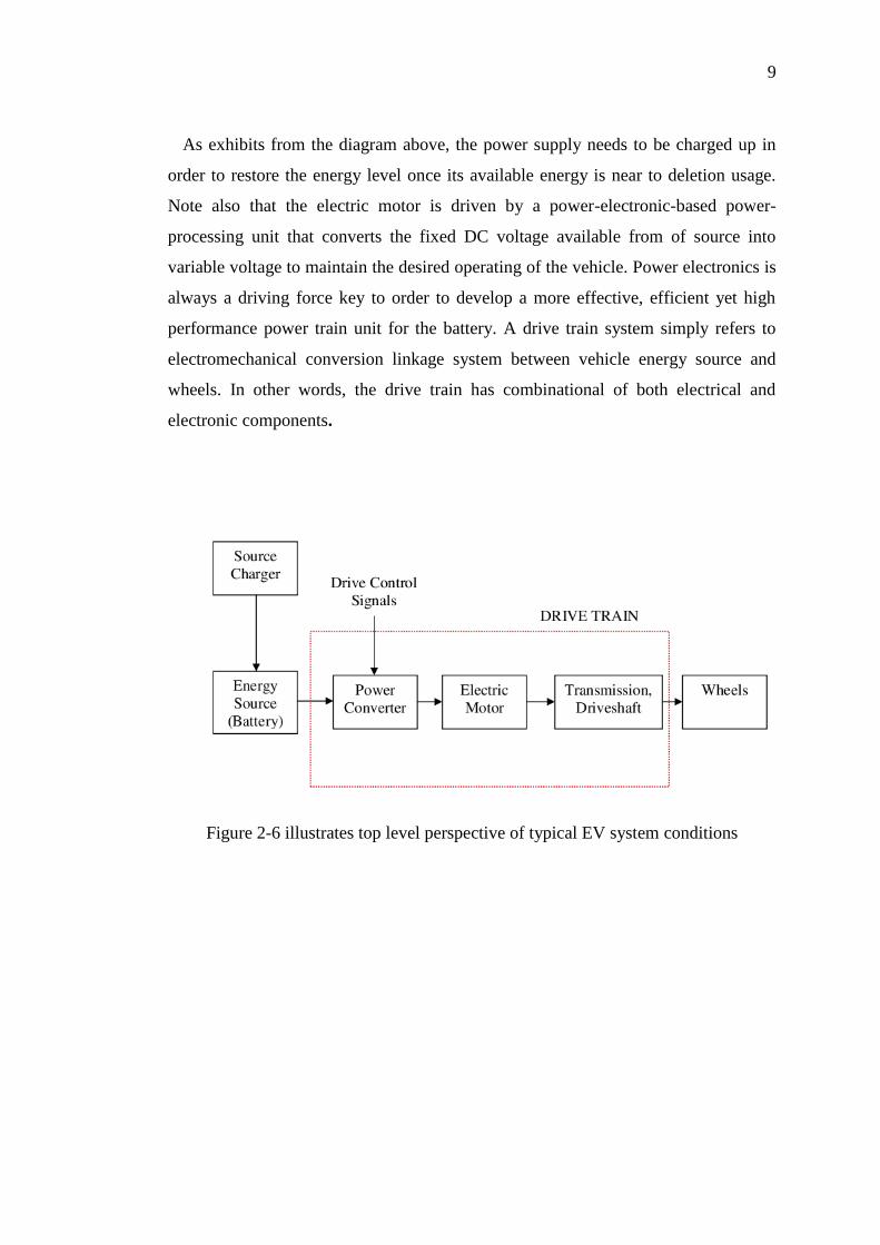
As exhibits from the diagram above, the power supply needs to be charged up in
order to restore the energy level once its available energy is near to deletion usage.
Note also that the electric motor is driven by a power-electronic-based power-
processing unit that converts the fixed DC voltage available from of source into
variable voltage to maintain the desired operating of the vehicle. Power electronics is
always a driving force key to order to develop a more effective, efficient yet high
performance power train unit for the battery. A drive train system simply refers to
electromechanical conversion linkage system between vehicle energy source and
wheels. In other words, the drive train has combinational of both electrical and
electronic components.
Figure 2-6 illustrates top level perspective of typical EV system conditions

10
2.4 Overview on EV’s Power Management System
Figure 2-7 shows a very fundamental idea on each module and every single module
integrated together in order to create an EV system

11
CHAPTER 3
3 METHODOLOGY
3.1 System Consideration
In this project, intelligent electric vehicle controller system, Intel atom board
(D510M0) and PICs microcontrollers will be used in this case in order to create a
stable and yet reliable system. Note that Intel atom board does not only provide great
opportunity for future implementations but more importantly unlike any other
processors, it does not consume a lot of power. Hence, in my opinion, it is the one of
the most suitable tools to be used as an embedded system of the vehicle.
Besides building and compiling kernel from scratch by repackaging Ubuntu
distribution like any embedded system, Linux OS typically Ubuntu 10.10, is being
installed on this system. With an OS, generally things become easier as most of the
drivers and libraries are right there for us. Moreover, there are also lots of open
source codes available in the internet relating to Linux OS which can be used on this
project. Take note also that kernel building and compilation may takes up a lot of
time and yet it may not be very successful due to software issue. As a result OS is
being installed directly instead.
Now let us take a closer look at storage devices that are available to us to
hold the contents of this OS. Some of these storage media are hard disks, floppy disk,
Zip disk, CDs, DvDs, tape, PC cards, flash memory card, USB flash drive and
microfilm. However, since this system is design for an embedded system towards
vehicle industries, SSD (solid state hardisk) would be most preferred solution as it

12
does not only has large storage capacity in nature but more importantly it does not
have any mechanical parts. Having no mechanical parts in SSD simply implies that
SSD can be avoided from damage due to vehicle shaking caused by uneven surface.
In order to start off with this project, a bootable flash drive with Linux OS
lies on to it is created. This however serves as one of the methods to install Linux OS
on to a SSD. Since, the price of a SSD is exorbitant in the market; normal hardisk is
used instead. A bootable Linux USB flash drive can easily be created using
Universal-USB-Installer-1.8.2.6, as shown in the figure below.
Figure 3-1 shows Universal-USB-Installer-1.8.2.6 in action
Figure 3-2 illustrates Intel board configuration
Besides that, since the I/O card expansion is not widely used in the computer
industries, yet very expensive. To overcome this problem, in term of saving time and

13
cost, PIC is being used instead. In this event, serial has to be taken in place. Further
elaboration on this design will be discussed in the following chapter.
3.2 Software Consideration
Another most essential design is none other than graphic user interface (GUI).
GUI provides easy navigation for user to communicate. This means that designed
GUI must not only be interactive but also able to provide an easy way as a mean of
communication to the users. There are many ways available for us to design GUI on
Linux OS. Some of these languages are python script, shell script, perl script,
Gambas (visual basic in Linux OS), Linux C programming (Gnome programming
using GTK+) and many more.
The easiest way out in order to design GUI is by using Adobe Flash (action
script 3.0). Through this way, Application Programmable Interface, API can easily
be created by underlying all the database programming underneath the GUI.
Moreover, with the use of adobe flash, GUI can easily be developed within a short
period of time.
Figure 3-3 Adobe Flash (CS5)

14
Database such as XML playlist can simply be created by using standard shell
called bash which is better known as GNU Bourne Again Shell, from the GNU suite
tools. Since this is an excellent shell that is always installed on Linux Systems, open
source, and is portable to almost all Linux variant, shell is indeed the best tool to
handle the entire database within Linux OS. Of course, with the used of shell script,
the level of complexity of a particular code can easily be reduced. Obviously, one
must be very well versed in that language. Nevertheless, having the knowledge of
Advanced Shell Script may even simplify shell script coding further. This however
may not be a good as compared to install Linux natively on the OS. This is because
running two OS simultaneously on top of one another may result in the losses of
RAM size during execution.
Figure 3-4 Running Ubuntu 10.10 OS using Vmware Workstation
3.3 Hardware Consideration
For hardware implementation, at this point AGM lead-acid will be used as a
first testing ground for the overall EV project. Of course, Lithium Polymer (LiPo)
battery will be coming into the whole picture once every testing concerning lead acid
battery has been done. This however could be done in the second phase of this
project.

15
Next, in order to ensure that the power management system able to run within
the whole vehicle, only one lead acid maintenance free battery (12V, 75AH) will be
used in this design. The whole idea behind this is to model the overall EV having
one enormous power source, approximately 196V of lead acid battery. In addition to
that, some of the BMPS feature such as cell monitoring and smart cell isolation will
not be taken into consideration since our battery sponsorship willing to do battery
research just to produce battery suitable to be used on our EV prototype.
Figure 3-5 16 Lead Acid Batteries from Yokohama for EV testing
Hardware design for this project covers battery monitoring system ranges
from monitoring battery status to temperature monitoring system. In this design,
watchdog timer will also be taken into consideration, in order to verify that sensors to
be used in monitoring those applications are working properly from time to time.
Apart from that, before proceeding any further in the design, it is very imperative for
us to understand the motor characteristic (torque profile) and state of charge (SOC)
before determining safe operating area (SOA) of the battery. Both of these studies
will be carried out my colleagues. In this testing, we will be running on motorcycle‟s
motor which then acts as a load for the whole system, as exhibits in the figure below.
Note that the batteries must be connected directly to its controller (drivers) before it
is ready to be coupled to the load.

16
Figure 3-6 Motors and its controller from Yokohama for EV testing
The fundamental connection concept between the battery, controller and
motor are almost the same as exhibits in the figure below.
Figure 3-7 Fundamental Concept of Acceleration Pedal in an EV
As seen from the figure above, the variation in speed of the motor is typically
controlled by PWM (Pulse Width Modulation). A simple circuit has been developed
to fully understand the DC controller‟s mechanism. In this circuit design, variation in
both speed and direction can easily be achieved. On top of that, modelling of the
vehicle‟s stop behaviour can also be attained when the potentiometer (direction and
speed controller) is adjusted to a specific value. To achieve this, the potential drops
across the potentiometer must be approximately 5V for the reason that both of the
op-amps will not be set as high. This simply means that none of the transistors are
17
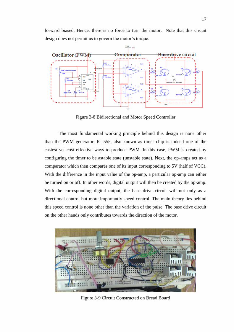
forward biased. Hence, there is no force to turn the motor. Note that this circuit
design does not permit us to govern the motor‟s torque.
Figure 3-8 Bidirectional and Motor Speed Controller
The most fundamental working principle behind this design is none other
than the PWM generator. IC 555, also known as timer chip is indeed one of the
easiest yet cost effective ways to produce PWM. In this case, PWM is created by
configuring the timer to be astable state (unstable state). Next, the op-amps act as a
comparator which then compares one of its input corresponding to 5V (half of VCC).
With the difference in the input value of the op-amp, a particular op-amp can either
be turned on or off. In other words, digital output will then be created by the op-amp.
With the corresponding digital output, the base drive circuit will not only as a
directional control but more importantly speed control. The main theory lies behind
this speed control is none other than the variation of the pulse. The base drive circuit
on the other hands only contributes towards the direction of the motor.
Figure 3-9 Circuit Constructed on Bread Board
18
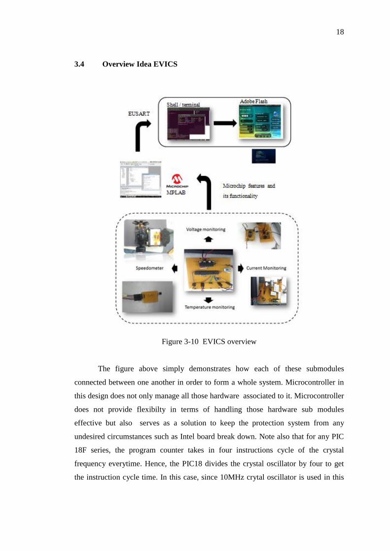
3.4 Overview Idea EVICS
Figure 3-10 EVICS overview
The figure above simply demonstrates how each of these submodules
connected between one another in order to form a whole system. Microcontroller in
this design does not only manage all those hardware associated to it. Microcontroller
does not provide flexibilty in terms of handling those hardware sub modules
effective but also serves as a solution to keep the protection system from any
undesired circumstances such as Intel board break down. Note also that for any PIC
18F series, the program counter takes in four instructions cycle of the crystal
frequency everytime. Hence, the PIC18 divides the crystal oscillator by four to get
the instruction cycle time. In this case, since 10MHz crytal oscillator is used in this

19
project, the instruction cycle frequency 2.5MHz. This basically means that the PIC
response time is to peform isolation takes about 400ns .
EUSART is used as a mean to interface to Intel atom board. Since serial only
enable one to send one character at a time. These characters must correspond to a
unique value in order to be able for board to distinguish among themselves so that it
knows where to be updated in the GUI. There is no way for flash to update itself
which is why shell script as known as bash script is introduced. Shell script is used in
this project to manipulate suitable result to be process by Adobe flash player, web
server application, and not be left out file to be copied to flash drive.
Copy to flash drive application can easily be obtained by combining mdm 3.0
features together with action script. With this manner, one can easily write to a file,
say text file. Once this text file has been updated, shell script can easily be written to
carry out a specific task within an operating system.
Webserver application can easily be set up also be set up with the use of
antiweb httpd. As discussed earlier, bash shell script can also be used as a tool to
update DHTML. Dynamic HTML (DHTML), enable technicians to obtain
information vehicle information directly with the used of website connected
wirelessly. On top of that, technicians also enable to access past vehicle records of
one vehicle before start to mend. In this case, one is able determine vehicle problem
easily. In this case, once the technicians finished repairing, they have to update the
vehicle‟s database.
20
CHAPTER 4
4 RESULTS AND DISCUSSIONS
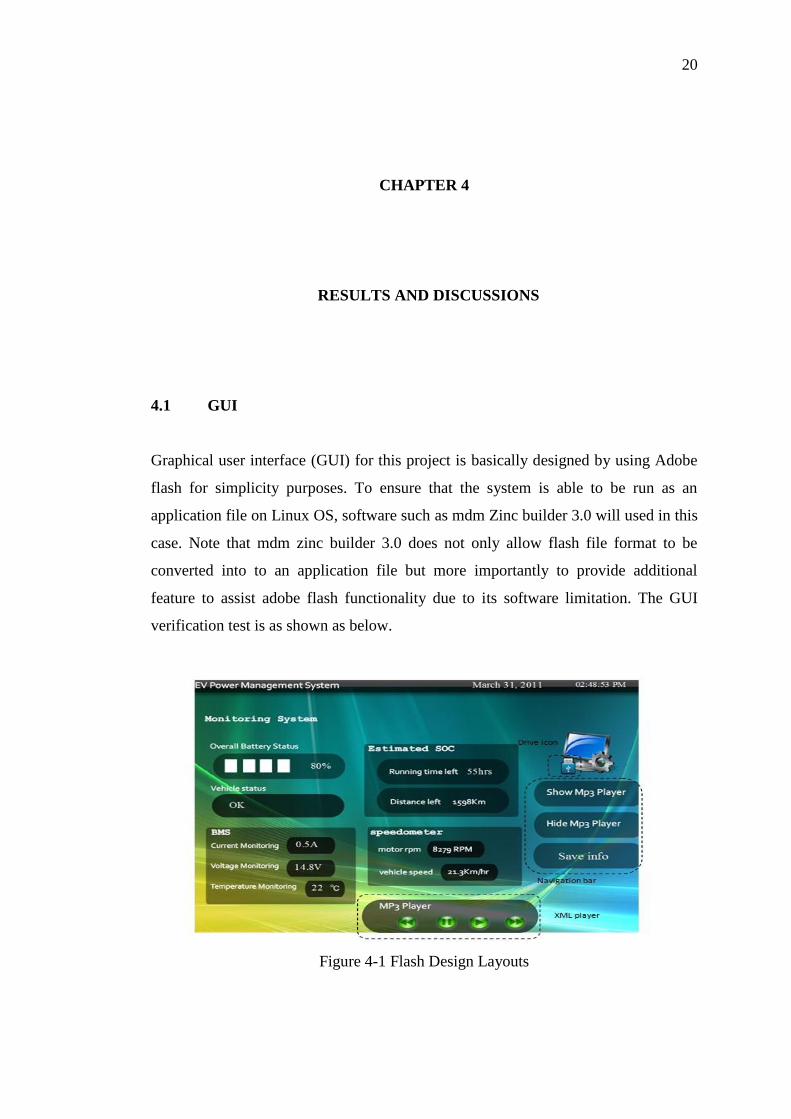
4.1 GUI
Graphical user interface (GUI) for this project is basically designed by using Adobe
flash for simplicity purposes. To ensure that the system is able to be run as an
application file on Linux OS, software such as mdm Zinc builder 3.0 will used in this
case. Note that mdm zinc builder 3.0 does not only allow flash file format to be
converted into to an application file but more importantly to provide additional
feature to assist adobe flash functionality due to its software limitation. The GUI
verification test is as shown as below.
Figure 4-1 Flash Design Layouts

21
4.1.1 GUI Simulation based on Different conditions
Figure 4-2 Dangerous zone
Figure 4-3Hide Player

22
Figure 4-4 No Flash Drive Detected
Figure 4-5 Flash Drive Detected

23
4.2 XML Player
XML player in this project serves as an additional feature for users to play
songs while they are on the road. To keep the system as simple as possible, the XML
player will only play mp3 file format. XML player simply indicates that the player
only plays song generated by the XML file. An XML file, in this case, playlist.xml
keeps all the songs directories once a flash drive is plug into the system. Once the
play button is pushed, each of the songs will be played respectively according to their
turn. Note that the playlist must be dynamic as it changes from time to time.
Figure 4-6 XML Player GUI
Next, there is no way for us to update time and date of GUI from time to time.
Hence, dynamic text with a little bit of Action Script 3.0 (AS 3) is written to support
that application. With the used of this dynamic time generation, updated XML
database, generated by unix shell script every 1 second will be read then by flash
player. In this case, the number of flash drive and its content will be up to date every
microprocessor‟s clock cycle. This simply means that the flash player has to be
updated by unix shell script and without it would be nothing but a static system.
The dynamic XML of a system typically, Linux OS can easily be written in
various languages but in this case bash script is considered it is indeed one of the
easiest ways to create dynamic database within a Linux webserver, CGI – Common
Gateway Interface. Of course, according to Linux GNU programming, Linux C
programming language can also be written to replace bash shell script, however one
must be very familiar with GNU libraries. Moreover, note that unlike any bash script
programming, Linux C programming must be compiled first before it is ready for
execution.

24
Figure 4-7 Linux Kernel
Now let us look into flash drive detection. In Linux OS it is very obvious that
USB storage devices will be auto mounted to the /media directory directly, as shown
in the figure above. Hence, the next stage would be nothing more than searching for
mp3 songs from this location. Once the locations of the songs are grabbed, they are
then dumped into playlist.xml. The XML generally holds the entire songs location
database inside a flash drive. As discussed, the XML database enables this player to
know which songs to be played at an instance of time besides providing its location.
Anyway, searching or even creating dynamic XML file was not as tricky as detecting
the presence of flash drive. In this case, the source code should not only be able to
perform checking, monitoring device every 1 second within the system but also
updating XML file once changes has been detected.
Crontab is generally a program that does task scheduling under Linux OS. In
other words, commands or even programs can be executed scheduler based on a
specific time attached to that task. This time frame could be as simple as a date or
subroutine. To have a better picture concerning subroutine, let us imagine of a task,
say XML bash script gets executed every one seconds, the complexity of writing a
source code can be reduced. Unfortunately, the slightest subroutine time frame on
this system can never be less than 1 minute. Thus, it may not be very so practical to
the users (there a long pause in the system – delay). In this case, it is understood that
the scheduler‟s deamon gets executed every 30 seconds. Moreover, it is learnt that
crontab can never execute script that contains continuous while loop. From
observation, setting the crontab to execute a script during boot up (only once – no
subroutine) does not really going to help much since the program stops its execution
when it sees while loop.

25
To solve this problem, the shell script is written in a form of application
program. In this case, the file is created such that it will launch basic terminal before
executing a program attached to it. This can be achieved by making another bash
script file to call for the main program (XML bash script program) upon execution.
Once this is ready, it is then to be placed in on Linux start up system called (system -
> preferences -> startup applications preferences) upon ready to for execution
during the next start up. To have a better illustration, please refer to the figure below.
Figure 4-8 Bash Script together with its launcher
Figure 4-9 Launcher Program in Action Searching for Drive

26
Figure 4-10 Launcher Program detected the existence of Flash Drive
Figure 4-11Similar Program running on Linux Shell

27
Figure 4-12 Block Behind Flash Drive Detection
Now let us take a closer look at the project modular design in order to
understand the program flow better. As seen from the figure above, a.sh is typically a
file that calls for an external terminal that is ready to execute another source code, in
this case, active.sh. The source code acive.sh typically checks the media directory for
any changes (every one second). Once it detects any changes it will write songs url
content and name of the flash drive connected to the system directly with the
corresponding XML tag. Flash drive detection not only used as mean to detect
numbers of songs that a system has but more importantly to be used as mean transfer
file directory. Without showing the name for each of the flash drives connected to a
system, one is unable to determine where the most updated monitoring status file to
be copied to. Apart from that to avoid from any circumstances, the XML player is
designed to play mp3 format on XML player.
XML player in flash player on the other hand can easily be designed by using
AS 3 (action script). The play function does not differ much as compared to any

28
other functions of the XML player - they all response to mouse click. As a
consequence, the source code for each of these functions will look almost the same
as one another. The word “play_btn” simply refers to name attached towards the
play symbol. From the source code below, once “play_btn” is clicked onPlay
function will then be executed.
AS 3.0 – play function
play_btn.addEventListener(MouseEvent.CLICK, onPlay);
function onPlay(e:MouseEvent):void
/*add source code here*/
The next function is certainly a very tricky utility to be handled. From the
source code, it is clearly understood that onNext function may not necessary comes
from mouse click. It may also come from playSong function since it has to start
playing the next song once the current song has already been played. Next, slight
modification in the source code has been made to the onNext function by making it
responses to all sorts of events. Note that mouse click is just one of an event in this
case. Part of the source code is as shows as below.
AS 3.0 – Moves to the Next Song
/*function designed to play a song */
function playSong(mySong:Number):void
…
my_channel.addEventListener(Event.SOUND_COMPLETE, onNext);
/*using playSong function to call for onNext function*/
next_btn.addEventListener(MouseEvent.CLICK, onNext);
function onNext(e:Event):void /*event */
/*add source code here*/

29
4.3 GUI Dynamic Time and Date Generation
Figure 4-13 Upper top of EV GUI
There is no way for us to update time and date of GUI from time to time.
Hence, dynamic text with a little bit of Action Script 3.0 (AS 3) is written. With the
used of dynamic time generation XML database will only be read every 0.25 second
at a time. This is essential to avoid the system from crash. Imagine that system tries
to read from the database every instruction cycle – not necessary one second. Part of
the source code is as shown as below. Do take note that the tick function takes place
every 500 ms.
AS 3.0 – Dynamic Reading from XML Database
function tick(event:TimerEvent):void
updateTimer(); /*functions that gets date and time */
/*loading playlist.xml to be used in processXML function */
var myXMLLoader:URLLoader = new URLLoader();
myXMLLoader.load(new URLRequest("playlist.xml"));
myXMLLoader.addEventListener(Event.COMPLETE, processXML);
Time and date has to be updated dynamically using dynamic text as discussed.
Each of these dynamic text created must be given a name in order to for us to
distinguish among them. In this case, “timetxt” and “datetxt” are names that given to
the time and date respectively. Note that the date that attained in this project is not
written in string data type. Therefore, they are then being transformed with the used
of pad(argument) function. The add symbol simply denotes appending all the strings
together as one entire string.
30
AS 3.0 – Date and Time Generation
function updateTimer():void
var date = new Date(); /*gets date from the system*/
…
/*display time and date using string data type*/
timetxt.text = hours_check(hours) + ":" + pad(mins)+ ":" + pad(secs) + " " +daylight;
datetxt.text = monthconvert(month) + " " + day + ", " + year;
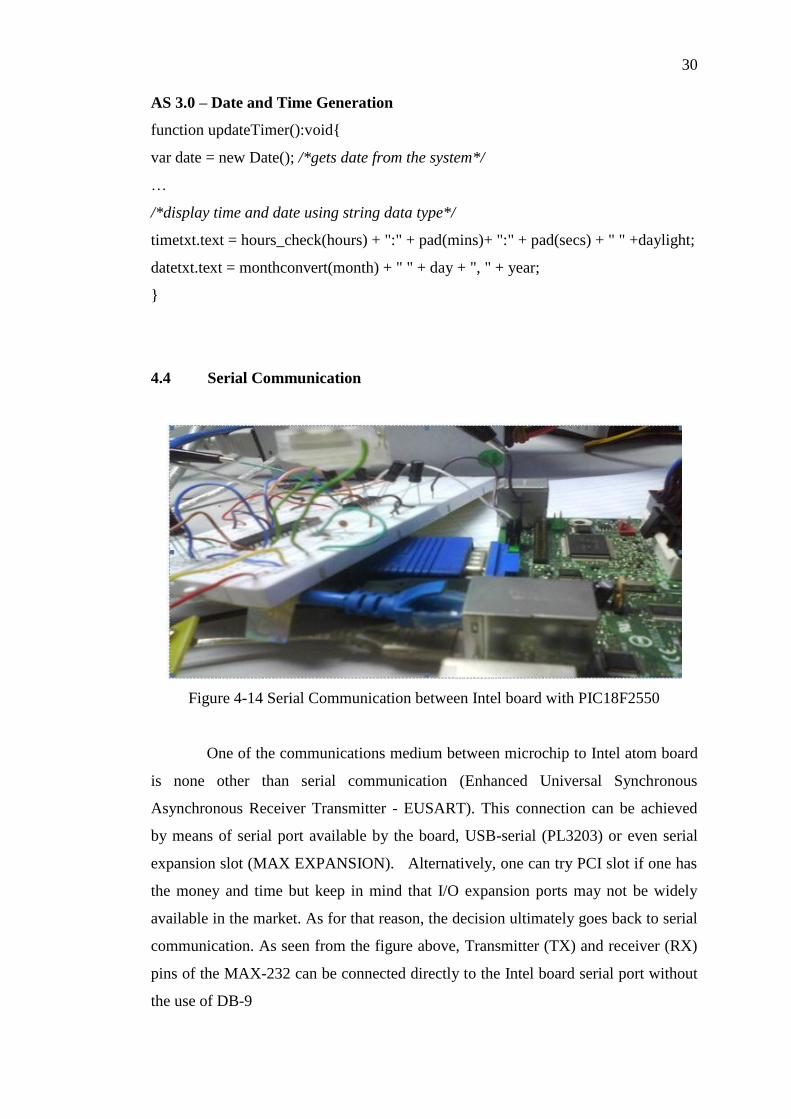
4.4 Serial Communication
Figure 4-14 Serial Communication between Intel board with PIC18F2550
One of the communications medium between microchip to Intel atom board
is none other than serial communication (Enhanced Universal Synchronous
Asynchronous Receiver Transmitter - EUSART). This connection can be achieved
by means of serial port available by the board, USB-serial (PL3203) or even serial
expansion slot (MAX EXPANSION). Alternatively, one can try PCI slot if one has
the money and time but keep in mind that I/O expansion ports may not be widely
available in the market. As for that reason, the decision ultimately goes back to serial
communication. As seen from the figure above, Transmitter (TX) and receiver (RX)
pins of the MAX-232 can be connected directly to the Intel board serial port without
the use of DB-9

31
Besides that to ensure that serial communication between the PIC and the
Intel board has been established, PIC18F2550 under Linux Operating System,
software such as GTKterm, minicom, moserial and Terminal had been tried out.
However, at the end of the day only terminal will considered since it has the
capability to store whatever it has received from serial just with use of shell script
(similar concept to XML generation).
Figure 4-15 Serial Communication using moserial
From our discussion above, it is easily noted that shell script does not only
plays an imperative role in terms of database programming ( creating dynamic XML)
but more importantly serves as intermediate system ensuring that Adobe Flash is able
to tag along with serial communication which is then attached to PIC. As stated,
there no ways for Adobe flash to obtain information directly from PIC just by using
serial communication‟s software as mentioned above. In other words, with the use
Linux programming, for instance shell script or GNU - C programming, suitable
dynamic data file can be created to suit the needs of AS 3. In this project, Linux shell
is used as a main tool to handle all of these applications.
32
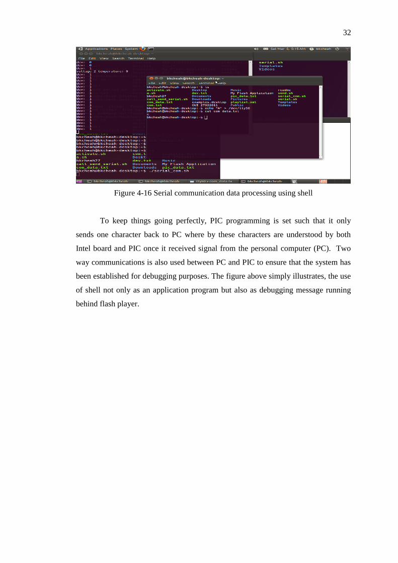
Figure 4-16 Serial communication data processing using shell
To keep things going perfectly, PIC programming is set such that it only
sends one character back to PC where by these characters are understood by both
Intel board and PIC once it received signal from the personal computer (PC). Two
way communications is also used between PC and PIC to ensure that the system has
been established for debugging purposes. The figure above simply illustrates, the use
of shell not only as an application program but also as debugging message running
behind flash player.
33
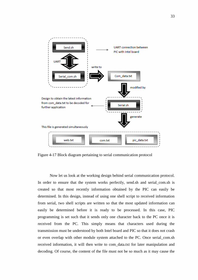
Figure 4-17 Block diagram pertaining to serial communication protocol
Now let us look at the working design behind serial communication protocol.
In order to ensure that the system works perfectly, send.sh and serial_com.sh is
created so that most recently information obtained by the PIC can easily be
determined. In this design, instead of using one shell script to received information
from serial, two shell scripts are written so that the most updated information can
easily be determined before it is ready to be processed. In this case, PIC
programming is set such that it sends only one character back to the PC once it is
received from the PC. This simply means that characters used during the
transmission must be understood by both Intel board and PIC so that it does not crash
or even overlap with other module system attached to the PC. Once serial_com.sh
received information, it will then write to com_data.txt for later manipulation and
decoding. Of course, the content of the file must not be so much as it may cause the

34
system response time to be very slow. As discussed earlier, a file is needed to
basically gets the most recent information and decode the information to some useful
information that people and action script (AS) 3.0 can understand. This is where the
file entitled serial.sh comes into picture. Text file entitled, pic_data.txt is designed so
that users are able download the monitoring results on the flash drive apart from
playing songs on the board itself. Com.txt on the other hand, serves as a
communication medium between flash player and bash script. Once, there is some
changes in the com.txt file, the flash player will ultimately vary as well.
4-1 Table shows each of the characters shared between Intel board and PIC

35
4.5 SOC Prediction Estimation
Figure 4-18 Prediction of battery running time and distance left
Another feature attached to the GUI is none other than battery predictions. With the
help of this module, one is able to prepare for the worst case scenario. This module
can easily be achieved based on some simple experiment. Based on the experiment, it
is easily observed that 1V drops across 12V, 75AH Yokohama battery, takes up
approximately 10 hours. In this experiment, to ensure that the results are practical,
the load used in this experiment is typically the integration of the entire sub module
together with speaker simulating the vehicle on the go. Of course, LCD monitor
screen will be used instead of touch screen devices in order to cut off some cost. The
Distance left can be computed easily by multiplying running time left with current
vehicle speed.
Figure 4-19 Power up the whole system using 75AH Yokohama battery
Battery pack

36
4.6 Webserver
Figure 4-20 Intel board connects to a router for wireless LAN connection
Another feature embedded into the board none other than to use the board as a
server. Of course, a wireless router has to be turned off in this case in order to
provide flexibility to the customer during servicing. Having such advantage,
technicians whom are servicing that vehicle can easily obtain battery profile
information and vehicle past records simply by connecting to the board via web
browser. In this case, the device can either be a personal computer or notebook
inclusive of todays‟ smart phones. In this case, one only has to know the board
board‟s IP address (static IP address set by a router – 192.168.0.102) and its port
number attached to the system. The port number, on the other hand, can easily be set
inside awhttpd.conf. 8384 is the port number set for this web application.
This can module can easily be implemented with the help of anti-web httpd.
An anti-web httpd is also known as a single process web server that relies on its
inherent simplicity to be robust and secure. It basically supports virtual hosts, CGI,
IPv6 and more. In this project, Common Gateway Interface (CGI) will be used
instead. CGI programming can easily be written as a mixture of bash scripts (server
side programming), HTML, javascript (client side programming), and CSS in order
37
to generate dynamic HTML with interactive feature and they normally placed in the
awhttpd/default directory. Of course in order to run the webserver application during
start up, crontab (linux scheduler) has to be used instead.
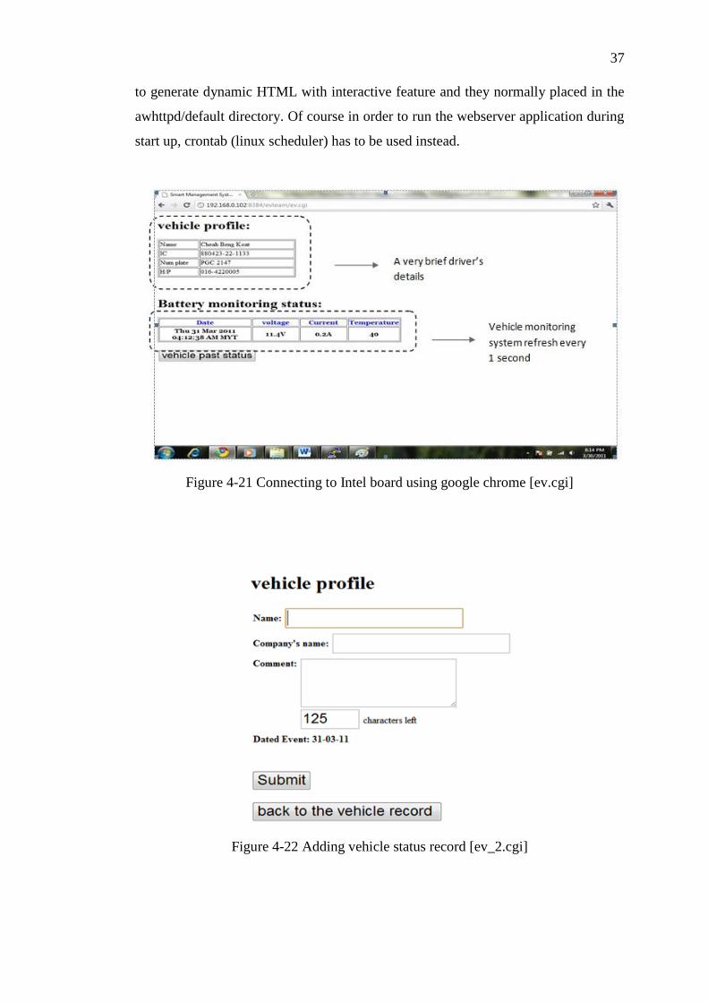
Figure 4-21 Connecting to Intel board using google chrome [ev.cgi]
Figure 4-22 Adding vehicle status record [ev_2.cgi]

38
Figure 4-23 View vehicle records [ev_1.cgi]
Figure 4-24 Block diagram behind webserver programming
On top of that with this wireless feature also enable Intel board to provide
flexibility especially to software engineers who are dealing with software issue. With
this, one need not even have to go to near the corresponding vehicle just to do
programming. All one has is nothing but connecting to the host computer via
wireless connection. This can be achieved by using putty (for window) and shell
(SSH – for Linux). By having this connection more than one programmer can gain
access to the board at an instant.

39
Figure 4-25 Connected to the Intel board via putty - Windows
Figure 4-26 Putty connection connecting windows to Linux

40
Figure 4-27 creating a new file called “new_file” in putty
Figure 4-28 connecting to Intel board using Linux OS through via SSH command
4.7 Stage 1 of Battery Monitoring System
Generally, as discussed above, there are mainly three main modules
concerning BMS. They are current monitoring system, voltage monitoring system
and temperature monitoring system.
coding to create
new file
New file created here
41
The current monitoring system plays a very important role in determining the
right amount to be injected into the battery terminal and at the meantime take
necessary a measurement if unexpected circumstances occur. In the purpose of
developing an effective yet efficient smart monitoring system, it is utmost important
for us to understand the battery charger‟s characteristic. Voltage monitoring and
temperature monitoring systems on the other hands are essential to ensure the safety
of the vehicle.
All of these monitoring systems can simply be achieved by using ADC
conversion of the PIC18F4680. With the use of PIC, not only numbers of wire
connection can be reduced, but more importantly enable us to perform direct
processing by connecting directly to the Intel board via Max-232. Reducing numbers
of wire will eventually enable one to obtain more accurate yet reliable result. Current
monitoring devices can easily be designed by placing a low resistance value in
between the charging circuit and the battery. These modules later have been followed
up by my fellow teammate, Kenny Gan and Gan Yu Han.
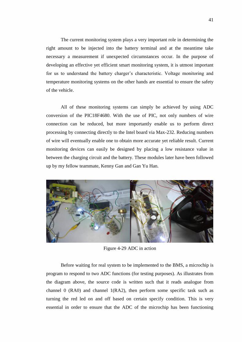
Figure 4-29 ADC in action
Before waiting for real system to be implemented to the BMS, a microchip is
program to respond to two ADC functions (for testing purposes). As illustrates from
the diagram above, the source code is written such that it reads analogue from
channel 0 (RA0) and channel 1(RA2), then perform some specific task such as
turning the red led on and off based on certain specify condition. This is very
essential in order to ensure that the ADC of the microchip has been functioning
42
properly. ADC input to the system in this case is model by potentiometer to model
variation in the BMS, as comprehended in the figure above. Later the red Led is
replace by a fan to confirm that the system able to trigger a transistor to power up a
fan as well. Of course, in this case, a capacitor is connected parallel with fan so that
there is enough current to produce sufficient to kick start a motor fan.
At this point, it is then realized that this project does not require a lot of ports.
This simply means that lesser circuit connections under micro-controller
implementation. Therefore, PIC18F4680 can simply be substituted by PIC18F2550
since it is best to implement everything inclusive of applications, functionalities
under one roof with a cheaper cost.
4.8 Copy Function from Adobe Flash Player
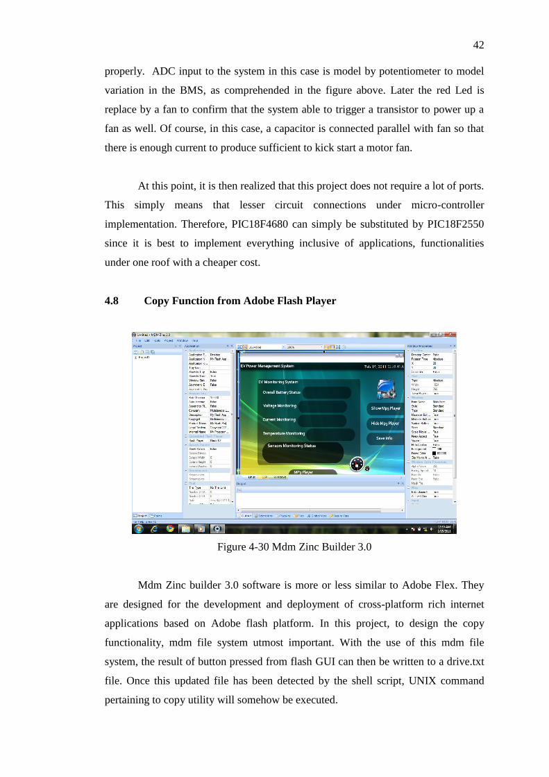
Figure 4-30 Mdm Zinc Builder 3.0
Mdm Zinc builder 3.0 software is more or less similar to Adobe Flex. They
are designed for the development and deployment of cross-platform rich internet
applications based on Adobe flash platform. In this project, to design the copy
functionality, mdm file system utmost important. With the use of this mdm file
system, the result of button pressed from flash GUI can then be written to a drive.txt
file. Once this updated file has been detected by the shell script, UNIX command
pertaining to copy utility will somehow be executed.

43
AS 3.0 – write to a file from Flash
function processXML(e:Event):void
var myXML:XML = new XML(e.target.data);
/*read XML file*/
if (dev_total == 0)
/*disable flash drive icon and save info navigation tool*/
else /*control invisiblility */
drive.visible = true;
save_txt.text="Save info"
save_info.visible=true;
save_info.addEventListener(MouseEvent.CLICK, function()gotoAndStop("three");
/*go to frame 3 and shows flash drive names connected on the system*/
switch (dev_total)
/*
The source code below gets the flash drive name from playlist.XML then display in
frame 3. Once the first object is pressed (obj1), say on one flash drive connected to
that system, the flash drive name will then be written on to drive.txt; ready to deploy
by shell scripts.
*/
case 1 : obj1.visible=true;
obj2.visible=true;
obj3.visible=false;
obj4.visible=false;
str=my_data[0].@URL /*get flash drive content */
nav1.text=str; /*Display dynamic text on the screen */
nav2.text="Back"
obj1.addEventListener(MouseEvent.CLICK,
function()mdm.FileSystem.saveFile("drive.txt", my_data[0].@URL ););
obj2.addEventListener(MouseEvent.CLICK, function()gotoAndStop("one"));

44
break;
… /*source code continue here*/
/*similar concept applies to case 2 and 3*/
)
//end if

45
CHAPTER 5
5 AWARDS AND ACHIEVEMENT
5.1 Research Paper Publications & Conference
B.K Cheah*, Y.H Gan, G.D Gan, Z.Y Phuan, M.K Yoong, C.K.Leong. K.W Chew,
“Case Study of EV Controller and Power Management System”, Malaysian
Universities Transportation Research Forum and Conference (MUTRFC), 21
December 2010, Uniten
Website:
http://www.uniten.edu.my/newhome/uploaded/coe_civil/mutrfc2010/020%20CASE
%20STUDY%20OF%20EV%20CONTROLLER%20AND%20POWER%20MANA
GEMENT%20SYSTEM.pdf
http://www.uniten.edu.my/newhome/uploaded/coe_civil/mutrfc2010/021%20UG.pdf
Z.Y Phuan* ,B.K Cheah, Y.H Gan, G.D Gan, M.K Yoong, C.K.Leong. K.W Chew,
“Design of Battery Pack For Electric Vehicle Based on Lithium-Ion Technology”,
Malaysian Universities Transportation Research Forum and Conference
(MUTRFC), 21 December 2010, Uniten
Website:
http://www.uniten.edu.my/newhome/uploaded/coe_civil/mutrfc2010/014%20DESIG
N%20OF%20BATTERY%20PACK%20fOR%20ELECTRIC%20VEHICLE%20B
ASED%20ON%20LITHIUM-ION%20TECHNOLOGY.pdf
46
G.D Gan*, B.K Cheah, Y.H Gan, Z.Y Phuan, M.K Yoong, C.K.Leong. K.W Chew,
“Studies of Electric Motors For Light-Weight Electric Vehicle”, Malaysian
Universities Transportation Research Forum and Conference (MUTRFC), 21
December 2010, Uniten
Website:
http://www.uniten.edu.my/newhome/uploaded/coe_civil/mutrfc2010/016%20STUDI
ES%20OF%20ELECTRIC%20MOTORS%20FOR%20LIGHT-
WEIGHT%20ELECTRIC%20VEHICLE.pdf
Y.H Gan*, B.K Cheah, G.D Gan, Z.Y Phuan, M.K Yoong, C.K.Leong. K.W Chew, “A
Study on Electric Car Chassis and Design Principle”, Malaysian Universities
Transportation Research Forum and Conference (MUTRFC), 21 December 2010,
Uniten
Website:
http://www.uniten.edu.my/newhome/uploaded/coe_civil/mutrfc2010/021%20A%20S
TUDY%20ON%20ELECTRIC%20CAR%20CHASSIS%20AND%20DESIGN%20
PRINCIPLE.pdf
C.K.Leong *, B.K Cheah, G.D Gan, Y.H Gan, Z.Y Phuan, M.K Yoong. K.W Chew,
“Ultra-Fast Charging System On Lithium Ion Battery”, IEEE (Sustainable Utilization
and Development in Engineering and Technology), 20 – 21 November 2010, UTAR
M.K Yoong*, B.K Cheah, G.D Gan, Y.H Gan, Z.Y Phuan, C.K.Leong. K.W Chew,
“Studies of Regenerative Braking In Electric Vehicle”, IEEE (Sustainable Utilization
and Development in Engineering and Technology), 20 – 21 November 2010, UTAR
47
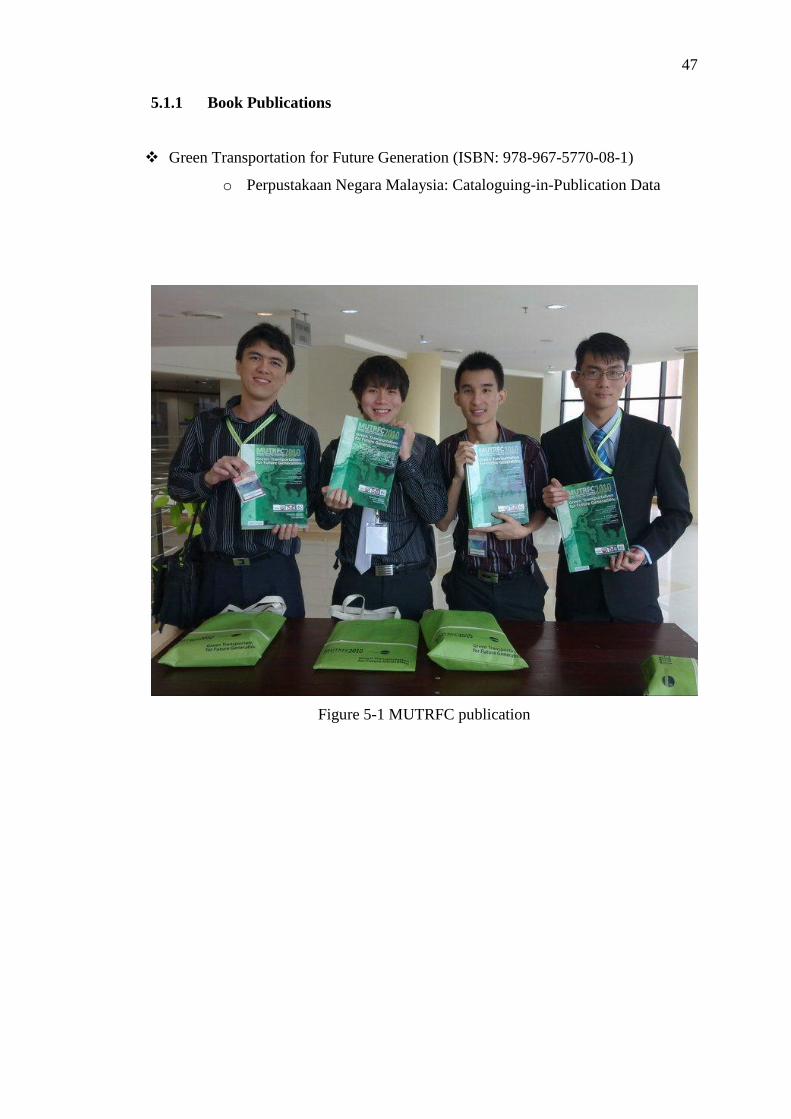
5.1.1 Book Publications
Green Transportation for Future Generation (ISBN: 978-967-5770-08-1)
o Perpustakaan Negara Malaysia: Cataloguing-in-Publication Data
Figure 5-1 MUTRFC publication

48
IEEE Student 2010 Project Exhibition
Figure 5-2 IEEE Student Exhibition
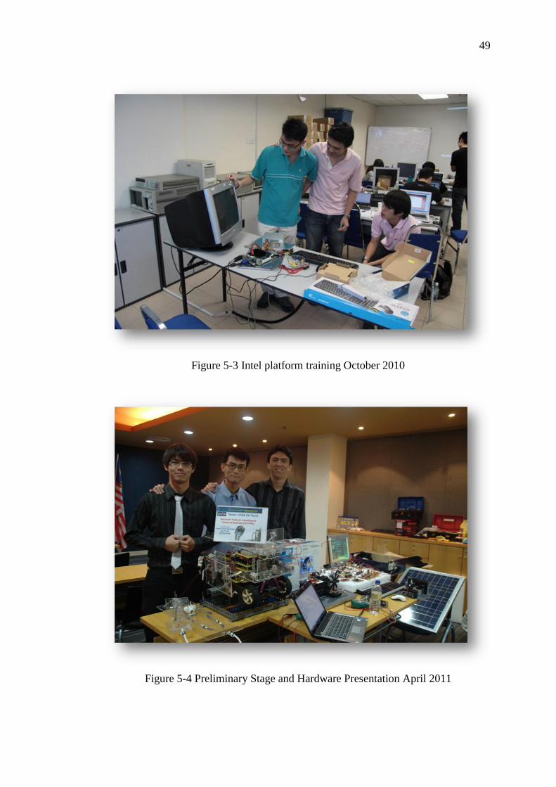
5.2 Innovate Malaysia Design Competition 2011 (Intel track)
For this project, three of members of our UTAR EV team, Gan Guo Dong, Gan Yu
Han and I had participated in the Innovate Malaysia Design Competition 2011 Intel
Track during May 2010 by making our final year project as part of the competition.
Through this competition we have gained a lot of experience. Some of these
experiences may include the Intel platform training at DreamCatcher, Penang in
October 2010 for three days and the Preliminary Stage and Hardware Presentation at
MSC Malaysia Innovation Centre, Cyberjaya in April 2011. Apart from that, our
Utar EV team has also been shortlisted as one of the top 5 teams that made it to the
grand finale.
49
Figure 5-3 Intel platform training October 2010
Figure 5-4 Preliminary Stage and Hardware Presentation April 2011

50
CHAPTER 6
6 CONCLUSION AND RECOMMENDATIONS
6.1 Recommendations
Figure 6-1 webcam application written in action script
In this project, there are lots of rooms for improvements. Webcam application
can easily be used to be interfaced to the Intel board for reversed parking utility. On
top of that with distance measurement devices, users are not only able to determine
how close in terms of visual but more importantly knowing it on the display itself.
Besides that creating a LAN connection for the technicians as a mean to
trouble shoot a vehicle effectively and efficiently, one must not only stop over here.
Developers should the system connected through the internet. Of course, the

51
information must be security enable to avoid hackers. Through this idea, technicians
from different area are able to provide their suggestion on how to improve the system
once they have received a real time data. Apart from that, future developers should
also a data logger to keep all the dangerous state information that takes place within
the vehicle. With some of these additional features, I believe technicians are able to
develop trouble shoot the vehicle better.
Next GPS module can also be integrated into the Intel atom board to improve
one‟s life style. With this, users do not only able to know where they are but more
importantly, they are able to determine where is the nearest charging station when
they really need one. Besides that, with advancement of technology in the IT area,
developers can also look into smart system embedded in vehicle. In this case, the
developers can design their system such that the system is able to provide real time
information which then enables users to make decision effectively. Those types of
information include, parking space availability, LRT expected arrival time, weather
forecast, and many more.
6.2 Conclusion
In this project, EVICS at this current stage, it is designed to handle power
management system of the vehicle by integrating all those monitoring system
together and at the same time perform necessary action once the system detects
dangerous area. These monitoring systems include voltage monitoring, current
monitoring, temperature monitoring and speedometer. Since this quite is an
enormous project, I will be the one fully take charge in software architecture design.
In this design, various programming languages had been used as a mean to integrate
all the system together. These languages include mcc18 (C programming -PIC), shell
script, JavaScript, CSS, HTML and action script. Note that the programming flow in
this design is very critical in order to ensure that the system is fully functional.

52
REFERENCES
Battery Management Systems (BMS) [Battery Management System for EV]. (n.d.). Retrieved
July 8, 2010,from Woodbank Communications.Batteries and Energy Storage Magazine
(BESTMAG) website: http://www.mpoweruk.com/bms.htm
Dallas Semiconductor. (n.d.). DS2751 Multichemistry Battery Fuel Gauge [Data Sheet
Specification on DS2751]. Retrieved July 20, 2010, from
http://www.alldatasheet.net/datasheet-pdf/pdf/114374/ MAXIM/DS2751.html
Guokai Xu, Xiuchun Zhao, Hang Su, & Zhenqiang Yang. (2008, June 1). [Review of the
controller main and control circuit]. A Pulse-width Modulation Based DC-DC Converter
for Electric Propulsion, 6(1), 1-3.
LITHIUM BALANCE A/ S. (n.d.). Case Study High speed Electric Vehicle [Lithium Battery
Management System]. Retrieved July 17, 2010, from
http://www.lithiumbalance.com/attachments/article/88/CaseStudyHighspeedElectricVehi
Cas.pdf
M J Schofield. (n.d.). The Controller Area Network (CAN) [key feature of CAN]. Retrieved
July 15, 2010, from http://www.mjschofield.com/
Microchip Technology Inc., T. C., & Microchip Technology Inc., S. D. (n.d.). "Developing
Affordable Mixed-Signal Power Systems for Battery Charger Applications" [Lithium Ion
Charging Profile].
Retrieved July 21, 2010, from
http://www.microchip.com/stellent/groups/designcenter_sg/documents/market_communi
cation/en027883.pdf
Mr PenyuBiru ·. (2009, July 20). Proton Saga Ev concept [Online forum message]. Retrieved
from http://carca-marba.blogspot.com/2009/07/proton-saga-ev-concept.html
Sandeep Dhameja. (2002). ELECTRIC VEHICLE BATTERY PERFORMANCE. In
ELECTRIC VEHICLE BATTERY SYSTEMS (p. 133) [Afterword]. (Original work

53
published 2002) Retrieved from http://www.pdfoo.com/ ebook-16617/electric-vehicle-
battery-systems.html
Zanthic Technologies Inc., S. D. L. (2008, June 25). A low cost Lithium Ion battery
management system for a multi-cell, high voltage battery pack [Low Cost Lithium
Battery Management]. Retrieved July 20, 2010, from http://www.zanthic.com/images/
A%20low%20cost%20Lithium%20Ion%20batter %20management%20system.pdf
54
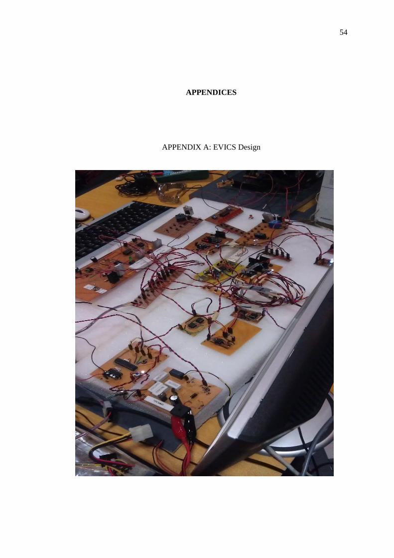
APPENDICES
APPENDIX A: EVICS Design

55
56
APPENDIX B: AS 3.0 GUI Source code
/********************************************
Title: time and date for the top bar
*********************************************/
var myTimer:Timer = new Timer(500);
myTimer.addEventListener(TimerEvent.TIMER,tick);
myTimer.start();
updateTimer();
var daylight:String="AM";
import mdm.*;
mdm.Application.init(this);
function tick(event:TimerEvent):void
updateTimer();
var myXMLLoader:URLLoader = new URLLoader();
myXMLLoader.load(new URLRequest("playlist.xml"));
myXMLLoader.addEventListener(Event.COMPLETE, processXML);
var urlLDR:URLLoader=new URLLoader();
var urlR:URLRequest=new URLRequest("com.txt");
urlLDR.addEventListener(Event.COMPLETE,f);
urlLDR.load(urlR);
/**
var myXMLLoader:URLLoader = new URLLoader();
myXMLLoader.load(new URLRequest("dev.xml"));
myXMLLoader.addEventListener(Event.COMPLETE, devXML);
57
**/
function updateTimer():void
var date = new Date();
/*vince test module 2011*/
var secs:uint = date.getSeconds();
var mins:uint = date.getMinutes();
var hours:uint = date.getHours();
var day:String = date.getDate();
var month:String = date.getMonth();
var year:String = date.getFullYear();
timetxt.text = hours_check(hours) + ":" + pad(mins)+ ":" + pad(secs) + " "
+daylight;
//datetxt.text = day + " " + monthconvert(month) + " " + year;
datetxt.text = monthconvert(month) + " " + day + ", " + year;
function hours_check(hours_num:Number)
var new_num:String;
if (hours_num > 12)
hours_num=hours_num-12;
daylight="PM"
else
daylight="AM"
if (hours_num == 0)
hours_num=12;
new_num=pad(hours_num);
return new_num;
/*converting number into string*/

58
function pad(number:Number)
var new_num:String = String(number);
if(new_num.length < 2)
new_num = "0" + new_num;
return new_num;
function monthconvert(month_num:String)
var month_name;
switch(month_num)
case "0" : month_name = "Jan"; break;
case "1" : month_name = "Feb"; break;
case "2" : month_name = "March"; break;
case "3" : month_name = "April"; break;
case "4" : month_name = "May"; break;
case "5" : month_name = "June"; break;
case "6" : month_name = "July"; break;
case "7" : month_name = "August"; break;
case "8" : month_name = "Sept"; break;
case "9" : month_name = "Oct"; break;
case "10" : month_name = "Nov"; break;
case "11" : month_name = "Dec"; break;
default: month_name = "ERROR";
return month_name;
/********************************************
Title: Time and Date generation
*********************************************/
59
var my_songs:XMLList;
var my_total:Number;
var my_sound:Sound;
var my_channel:SoundChannel;
var current_song:Number = 0
var song_position:Number;
var song_paused:Boolean;
var init:Boolean=true;
var my_data:XMLList;// drive <dev>
var dev_total: Number;
var str:String;
function playSong(mySong:Number):void
var myTitle = my_songs[mySong].@TITLE;
var myArtist = my_songs[mySong].@ARTIST;
var myURL = my_songs[mySong].@URL;
/* songs metadata
title_txt.text = myTitle;
artist_txt.text = myArtist;
*/
if (my_channel)
my_channel.stop();
my_channel.removeEventListener(Event.SOUND_COMPLETE, onNext);/*remove
listener*/
my_sound = new Sound();
my_sound.load(new URLRequest(myURL));
my_channel = my_sound.play();
my_channel.addEventListener(Event.SOUND_COMPLETE, onNext); //jump to next
songs...
60
pause_btn.addEventListener(MouseEvent.CLICK, onPause);
function onPause(e:MouseEvent):void
if(my_channel)/*checking channel before exe...20110114*/
song_position = my_channel.position;
my_channel.stop();
song_paused=true;
next_btn.addEventListener(MouseEvent.CLICK, onNext);
//function onNext(e:MouseEvent):void
function onNext(e:Event):void /*This used to have MouseEvent, change it to
Event*/
current_song++;
if (current_song>=my_total)
current_song=0;
playSong(current_song);
prev_btn.addEventListener(MouseEvent.CLICK, onPrev);
function onPrev(e:MouseEvent):void
current_song--;
if (current_song<0)
current_song = my_total-1;
playSong(current_song);
61
play_btn.addEventListener(MouseEvent.CLICK, onPlay);
function onPlay(e:MouseEvent):void
if (song_paused)
my_channel = my_sound.play(song_position);
song_paused=false;
else if(init)
playSong(current_song);
init=false;
function processXML(e:Event):void
var myXML:XML = new XML(e.target.data);
my_songs = myXML.SONG;
my_total = my_songs.length();
my_data = myXML.DEV;
//str=my_data[0].@URL;//read from file
//trace(str);
dev_total = my_data.length();
if (dev_total == 0)
drive.visible = false;
gotoAndStop("two");
save_info.visible=false;
save_txt.text=""
else
drive.visible = true;

62
save_txt.text="Save info"
save_info.visible=true;
save_info.addEventListener(MouseEvent.CLICK,
function()gotoAndStop("three");
switch (dev_total)
case 1 : obj1.visible=true;
obj2.visible=true;
obj3.visible=false;
obj4.visible=false;
str=my_data[0].@URL
nav1.text=str;
nav2.text="Back"
obj1.addEventListener(MouseEvent.CLICK,
function()mdm.FileSystem.saveFile("drive.txt", my_data[0].@URL ););
obj2.addEventListener(MouseEvent.CLICK,
function()gotoAndStop("one"));
break;
case 2 : obj1.visible=true;
obj2.visible=true;
obj3.visible=true;
obj4.visible=false;
str=my_data[0].@URL
nav1.text=str;
str=my_data[1].@URL
nav2.text=str;
nav3.text="Back"
obj1.addEventListener(MouseEvent.CLICK,
function()mdm.FileSystem.saveFile("drive.txt", my_data[0].@URL ););
obj2.addEventListener(MouseEvent.CLICK, function()
mdm.FileSystem.saveFile("drive.txt", my_data[1].@URL ););
obj3.addEventListener(MouseEvent.CLICK,
function()gotoAndStop("one"));
break;
case 3 : obj1.visible=true;
63
obj2.visible=true;
obj3.visible=true;
obj4.visible=true;
str=my_data[0].@URL
nav1.text=str;
str=my_data[1].@URL
nav2.text=str;
str=my_data[2].@URL
nav3.text=str;
nav4.text="Back"
obj1.addEventListener(MouseEvent.CLICK,
function()mdm.FileSystem.saveFile("drive.txt", my_data[0].@URL ););
obj2.addEventListener(MouseEvent.CLICK,
function()mdm.FileSystem.saveFile("drive.txt", my_data[1].@URL ););
obj3.addEventListener(MouseEvent.CLICK,
function()mdm.FileSystem.saveFile("drive.txt", my_data[2].@URL ););
obj4.addEventListener(MouseEvent.CLICK,
function()gotoAndStop("one"));
break;
)
//end if
/********************************************
Title: scroll bar control
Module: This module reads file that written in a staright line..
*********************************************/
function f(e:Event)
var info:String;
var i:Number;

64
var str_status:String;
var str_vehicle:String;
var str_sensor:String;
var str_current:String;
var str_temp:String;
var str_rpm:String;
/*new modifiaction made*/
var temp_1:Number;
var new_result:Number;
/*
string uder modification to suit one needs
bkcheah 20110219
*/
info=e.target.data;
str_status=info.substring(0,1);
str_current=info.substring(1,2);
str_temp=info.substring(2,3);
str_rpm=info.substring(3,5); //2 numbers
//str_current=info.substring(5,7);
//str_temp=info.substring(7,9);
//str_char=info.substring(10,info.length);
//trace(str_status); //disp str;
/*volatage status and volatge monitoring system*/
switch(str_status)
case "1" : movieClip_2.visible = false;
movieClip_3.visible = false;
movieClip_4.visible = false;
movieClip_5.visible = false;
movieClip_6.visible = false;
batt.text="0%";
65
vol.text="9.5V";
bat.text="0hr"
vehicle.text="OK"
temp_1=0;
break;
case "2" : movieClip_2.visible = true;
movieClip_3.visible = false;
movieClip_4.visible = false;
movieClip_5.visible = false;
movieClip_6.visible = false;
batt.text="20%";
vol.text="10.5V";
bat.text="10hrs"
vehicle.text="OK"
temp_1=10;
break;
case "3" : movieClip_2.visible = true;
movieClip_3.visible = true;
movieClip_4.visible = false;
movieClip_5.visible = false;
movieClip_6.visible = false;
batt.text="40%";
vol.text="11.4V";
bat.text="20hrs"
vehicle.text="OK"
temp_1=20;
break;
case "4" : movieClip_2.visible = true;
movieClip_3.visible = true;
movieClip_4.visible = true;
movieClip_5.visible = false;
movieClip_6.visible = false;
batt.text="60%";

66
vol.text="12.8V";
bat.text="35hrs"
vehicle.text="OK"
temp_1=35;
break;
case "5" : movieClip_2.visible = true;
movieClip_3.visible = true;
movieClip_4.visible = true;
movieClip_5.visible = true;
movieClip_6.visible = false;
batt.text="80%";
vol.text="14.8V";
bat.text="55hrs"
vehicle.text="OK"
temp_1=55;
break;
case "6" : movieClip_2.visible = true;
movieClip_3.visible = true;
movieClip_4.visible = true;
movieClip_5.visible = true;
movieClip_6.visible = true;
batt.text="100%";
vol.text="15.8V";
bat.text="65hrs"
vehicle.text="OK"
temp_1=65;
break;
/*bkcheah special condition*/
case "0" : movieClip_2.visible = false;
movieClip_3.visible = false;
movieClip_4.visible = false;
movieClip_5.visible = false;
movieClip_6.visible = false;

67
batt.text="0%";
vol.text="<9.0V";
bat.text="0hr"
vehicle.text="Dangerous"
temp_1=0;
break;
case "7" : movieClip_2.visible = true;
movieClip_3.visible = true;
movieClip_4.visible = true;
movieClip_5.visible = true;
movieClip_6.visible = true;
batt.text="100%";
vol.text=">17V";
bat.text="75hrs"
vehicle.text="Dangerous"
temp_1=75;
break
/*sensor monitoring system*/
/*
switch(str_sensor)
case "0" : sensor.text="OK"
break;
case "1" : sensor.text="System Error" //yet to be modified
vehicle.text="Dangerous"
break;
*/

68
/*current monitoring system */
switch(str_current)
case "0" : cur.text="0.0A"
break;
case "1" : cur.text="0.2A"
break;
case "2" : cur.text="0.3A"
break;
case "3" : cur.text="0.4A"
break;
case "4" : cur.text="0.5A"
break;
case "5" : cur.text="0.6A"
break;
case "6" : cur.text="0.7A"
break;
case "7" : cur.text="0.8A"
break;
case "8" : cur.text="0.9A"
break;
case "9" : cur.text=">1.0A"
vehicle.text="Dangerous"
break;
/*temperature monitoring system*/
switch(str_temp)
case "0" : temp.text="<20"
break;
case "1" : temp.text=" 22"
break;
case "2" : temp.text=" 27"
break;
case "3" : temp.text=" 32"
69
break;
case "4" : temp.text=" 37"
break;
case "5" : temp.text=" 40"
vehicle.text="Critical Temp"
break;
case "6" : temp.text=">41"
vehicle.text="Dangerous"
break;
/*temperature monitoring system*/
switch(str_rpm)
case "00" : rpm.text="0 RPM"
speed.text="0 Km/Hr"
new_result=temp_1 * 0;
dist.text=pad_str(new_result);
break;
case "01" : rpm.text="1030 RPM"
speed.text="1.3 Km/Hr"
new_result=temp_1 * 1;
dist.text=pad_str(new_result);
break;
case "02" : rpm.text="3284 RPM"
speed.text="4.2 Km/Hr"
new_result=temp_1 * 4;
dist.text=pad_str(new_result);
break;
case "03" : rpm.text="5744 RPM"
speed.text="7.4 Km/Hr"
new_result=temp_1 * 8;
dist.text=pad_str(new_result);
break;
case "04" : rpm.text="8279 RPM"

70
speed.text="10.7 Km/Hr"
new_result=temp_1 * 11;
dist.text=pad_str(new_result);
break;
case "05" : rpm.text="10915 RPM"
speed.text="14.1 Km/Hr"
new_result=temp_1 * 14;
dist.text=pad_str(new_result);
break;
case "06" : rpm.text="13427 RPM"
speed.text="17.4 Km/Hr"
new_result=temp_1 * 17;
dist.text=pad_str(new_result);
break;
case "07" : rpm.text="15920 RPM"
speed.text="20.5 Km/Hr"
new_result=temp_1 * 21;
dist.text=pad_str(new_result);
break;
case "08" : rpm.text="18510 RPM"
speed.text="23.9 Km/hr"
new_result=temp_1 * 24;
dist.text=pad_str(new_result);
break;
case "09" : rpm.text="21213 RPM"
speed.text="27.3 Km/hr"
new_result=temp_1 * 30;
dist.text=pad_str(new_result);
break;
case "10" : rpm.text="23942 RPM"
speed.text="30.9 Km/hr"
new_result=temp_1 * 40;
dist.text=pad_str(new_result);
break;

71
case "11" : rpm.text="26614 RPM"
speed.text="34.3 Km/hr"
new_result=temp_1 * 34;
dist.text=pad_str(new_result);
break;
case "12" : rpm.text="29102 RPM"
speed.text="37.5 Km/hr"
new_result=temp_1 * 38;
dist.text=pad_str(new_result);
break;
/*converting number into string*/
function pad_str(number:Number)
var new_num:String = String(number);
new_num = new_num + " "+ "Km";
return new_num;
stop();
xml_player.addEventListener(MouseEvent.CLICK,
function()gotoAndStop("one"));
xml_exit.addEventListener(MouseEvent.CLICK, function()gotoAndStop("two"));

72
APPENDIX C: Mplab serial communication source code
#include <p18f2550.h>
#include <string.h>
#include <usart.h>
#pragma config WDT = OFF //watchdog timer off
#pragma config FOSC = HS
#pragma config USBDIV = 2
void send(char);
void init(void);
void main (void)
char data;
unsigned char battery='a';
unsigned char current='k';
unsigned char temp='s';
unsigned int i,j,k;
init();
while(1)
/*******************************************************
MODULE : VOLATGE INDICATOR
CTRL : AN0 [INPUT] RB0 [OUT]
********************************************************/
ADCON0=0b00000001; //AN0
ADCON0bits.GO_DONE = 1;
while(ADCON0bits.GO_DONE != 0);/

73
if ( ADRESL < 0xE0 && ADRESH==0b00)
//PORTBbits.RB0=0x00;
i=0;
//*******************************************************************
**********************
/* [PROGRAMMING SAMPLING] <USING RB2 TEMP OUTPUT> */
if ( ADRESL >= 204 && ADRESL < 224)//1.0
battery='q'; //100%
else if ( ADRESL >= 183 && ADRESL < 204)//1.0
battery='p'; //80%
else if ( ADRESL >= 163 && ADRESL < 183)//0.9
battery='o'; //60%
else if ( ADRESL >= 149 && ADRESL < 163)//0.8
battery='n'; //40%
else if ( ADRESL >=137 && ADRESL < 149)//0.73
battery='m'; //20%
else if ( ADRESL >=122 && ADRESL < 137)//0.67
battery='l'; //0%
else
/*PROTECTION CIRCUIT FOR LESS THAN 9V*/
if ( ADRESL < 122)
//PORTBbits.RB0=0xFF;
i=1;
battery='k';
else
i=0;
//PORTBbits.RB0=0x00;
////endif
else
//PORTBbits.RB0=0xFF;
battery='r';

74
i=1;
/*******************************************************
MODULE : CURRENT MONITORING SYSTEM
CTRL : AN1 [INPUT] OUTPUT RB1
********************************************************/
ADCON0=0b00000101; //AN1
ADCON0bits.GO_DONE = 1;
while(ADCON0bits.GO_DONE != 0);//Loop here until A/D
conversion completes
if ( ADRESL < 0x14 && ADRESH==0b00)
//PORTBbits.RB1=0x00;
j=0;
if (ADRESL >=0 && ADRESL <3)
current='a';
else if (ADRESL >=3 && ADRESL <5)
current='b';
else if (ADRESL >=5 && ADRESL <7)
current='c';
else if (ADRESL >=7 && ADRESL <9)
current='d';
else if (ADRESL >=9 && ADRESL <11)
current='e';
else if (ADRESL >=11 && ADRESL <13)
current='f';
else if (ADRESL >=13 && ADRESL <15)
current='g';
else if (ADRESL >=17 && ADRESL <19)
current='h';
else
current='i';

75
//endif
else
//PORTBbits.RB1=0xFF;
j=1;
current='j';
/*******************************************************
MODULE : TEMPERATURE MONITORING SYSTEM
CTRL : AN2 [INPUT] RB2 [OUT]
********************************************************/
ADCON0=0b00001001; //AN2
ADCON0bits.GO_DONE = 1;
while(ADCON0bits.GO_DONE != 0);//Loop here until A/D
conversion completes
if ( ADRESL < 0x54 && ADRESH==0b00)
//PORTBbits.RB2=0x00;
k=0;
if (ADRESL >= 0 && ADRESL < 41)
temp='s';
else if (ADRESL >= 41 && ADRESL < 51)
temp='t';
else if (ADRESL >= 51 && ADRESL < 61)
temp='u';
else if (ADRESL >= 61 && ADRESL < 72)
temp='v';
else if (ADRESL >= 72 && ADRESL < 82)
temp='w';
else
temp='x';
else
temp='y';
k=1;

76
//PORTBbits.RB2=0xFF;
/*******************************************************
MODULE : ACTION CONTROL MODULE
********************************************************/
if (i==1 || j==1 || k==1)
PORTBbits.RB0=0xFF;
else
PORTBbits.RB0=0x00;
/*******************************************************
MODULE : COMMUNICATION PROTOCOL
********************************************************/
while (PIR1bits.RCIF==0);
data = RCREG;
if ( data == 'A' )
send(battery);
else if ( data == 'B' )
send(current);
else if (data == 'C')
send(temp);
else
TXREG = data ;
;
void init(void)
TRISAbits.TRISA0=1;
TRISAbits.TRISA1=1;
TRISAbits.TRISA2=1;
TRISAbits.TRISA3=1;

77
/////////////////////////////////////
TRISAbits.TRISA4=1;
TRISAbits.TRISA5=1;
/////////////////////////////////////
TRISB=0x0;
TXSTA = 0x22;
RCSTA = 0x90;
SPBRG = 15;
TXSTAbits.TXEN = 1;
RCSTAbits.SPEN = 1;
ADCON1=0b00001010;
ADCON2=0b10100110;
void send(char c)
while (PIR1bits.TXIF == 0);
TXREG = c;

78
APPENDIX D: Bash Shell script
#Author: bkcheah
#Module: obtain flash drive name and song content to be written in playlist.xml
#File name: active.sh
#!/bin/bash
#XML generator
#!/bin/bash
#COLOR CONFIG MODULE ################################
color()
if [ $1 -eq 1 ];then
echo -en '\E[;32m'"\033[1m$2\033[0m" #GREEN
elif [ $1 -eq 2 ];then
echo -en '\E[;33m'"\033[1m$2\033[0m" #YELLOW
elif [ $1 -eq 3 ];then
echo -en '\E[;31m'"\033[1m$2\033[0m" #RED
fi
#DEBUG MESSAGE MODULE ###############################
debecho ()
if [ $2 -eq 1 ];then
# echo "$1" >&2
echo -en '\E[;35m'"\033[1m$1\n\033[0m" >&2
fi
count=0
flag=0

79
#SOURCE CODE STARTS HERE
declare -r deb=1 #SETTING FOR DBG_DEBUG
declare -r red=3 yellow=2 green=1
while [ 1 ]
do
echo `pwd`
#let count++
#echo "count: $count"
dev=`df -h | wc -l`
let dev-=6
echo "dev: $dev"
if [ $dev -eq 0 ];then
tmp=$dev
elif [ "$dev" -ne "$tmp" ];then
#`$HOME/Desktop/xml_generator.sh`
#echo "test"
#########################################
: > $HOME/playlist.xml
#`cd /media`
song_name=`find /media . -name "*.mp3"`
rows=`find /media . -name "*.mp3" | wc -l `
#song_name=`find media/ -name "*.mp3" -type f -print`
#rows=`find media/ -name "*.mp3" -type f -print | wc -l`
#echo $song_name
for ((i=0; i<$rows; i++))
do
tmp=`expr $i + 1`
TEMP[$i]=` echo -e "$song_name" | cut -d$'\x0a' -f$tmp`
done

80
######################################################
# ---------------------display test
for ((i=0; i<$rows; i++))
do
# echo "$TEMP[$i]"
color $green "$TEMP[$i]"
# debecho "$TEMP[$i]" $deb
done
#####################################################
#DESIGN TO BE WRITTEN IN XML FORMAT
echo "<?xml version=\"1.0\" encoding=\"utf-8\"?>" > $HOME/playlist.xml
echo "<PLAYLIST>" >> $HOME/playlist.xml
for ((i=0; i<$rows; i++))
do
echo "<SONG URL= \"$TEMP[$i]\">" >> $HOME/playlist.xml
echo "</SONG>" >> $HOME/playlist.xml
# debecho "$TEMP[$i]" $deb
done
############## PROGRAM ENDS HERE #####################
echo
color $red "program completed written to:"
tput sgr0
color $yellow " $HOME/playlist.xml"
####
file_name=`ls /media`
rows=`ls /media | wc -l`

81
debecho "$file_name" $deb
for ((i=0; i<$rows; i++))
do
tmp=`expr $i + 1`
TEMP[$i]=` echo -e "$file_name" | cut -d$'\x0a' -f$tmp`
done
# ---------------------display test
for ((i=0; i<$rows; i++))
do
#echo "$TEMP[$i]" >> $HOME/dev.txt
echo "<DEV URL= \"$TEMP[$i]\">" >> $HOME/playlist.xml
echo "</DEV>" >> $HOME/playlist.xml
done
echo "</PLAYLIST>" >> $HOME/playlist.xml
##########################################
flag=1
tmp=$dev
fi
if [ $dev -eq 0 -a $flag -eq 1 ];then
##############################################
: > $HOME/playlist.xml
##############################################
flag=0
fi
sleep 0.25
done

82
#Author: bkcheah
#Module: run active.sh file as an application file
#File name: a.sh
xterm -e "bash $HOME/activate.sh; bash"
#Author: bkcheah
#Module: communicate with serial communication [send]
#File name: send.sh
while [ 1 ];
do
#xterm -e "echo "hello" /dev/ttyS0 > com_data.txt; bash"
echo "A" > /dev/ttyS1 #current monitoring
sleep 0.25
echo "B" > /dev/ttyS1 #voltage monitoring
sleep 0.25
echo "C" > /dev/ttyS1#temperature monitoring
sleep 0.25
echo "D" > /dev/ttyS1#speedometer
sleep 0.25
done
#Author: bkcheah
#Module: communicate with serial communication [receive]
#File name: com_serial.sh
: > $HOME/com_data.txt #erase the content of com_data.txt
sleep 1 # delay upon reading module starts up
xterm -e "cat /dev/ttyS1 > com_data.txt; bash"

83
#Author: bkcheah
#Module: decode serial for GUI, webserver, and user content (pic_data.txt)
#File name: serial.sh
#File generated: com.txt, pic_data.txt,web.txt
while [ 1 ] #main controller
do
info=`cat com_data.txt`
info_line=`cat com_data.txt | wc -l`
for ((i=0; i<$info_line; i++))
do
tmp=`expr $i + 1`
TEMP[$i]=` echo -e "$info" | cut -d$'\x0a' -f$tmp`
done
#debug display verificaton test [bkcheah]
for ((i=0; i<$info_line; i++))
do
echo "temp_data[$i]: $TEMP[$i]"
done
#grap the most recent data... [bkcheah 2011]
#echo "$TEMP[(($info_line-1))]"
# module: modification status
if [ $info_line -gt 3 ];then
: > com_data.txt #clean file
echo "$TEMP[(($info_line-1))]" > com_data.txt
fi
case "$TEMP[(($info_line-1))]" in
a)
current=0

84
cur=0.0A
;;
b)
current=1
cur=0.2A
;;
c)
current=2
cur=0.3A
;;
d)
current=3
cur=0.4A
;;
e)
current=4
cur=0.5A
;;
f)
current=5
cur=0.6A
;;
g)
current=6
cur=0.7A
;;
h)
current=7
cur=0.8A
;;
i)
current=8
cur=0.9A
;;

85
j)
current=9 #protective system sctivated
cur=">1.0A"
;;
k)
voltage=0
vol="<9.0V"
;;
l)
voltage=1
vol=9.5V
;;
m)
voltage=2
vol=10.5V
;;
n)
voltage=3
vol=11.4V
;;
o)
voltage=4
vol=12.8V
;;
p)
voltage=5
vol=14.8V
;;
q)
voltage=6
vol=15.8V
;;
r)
86
voltage=7
vol=">16V"
;;
s)
temperature=0
temp="<20"
;;
t) temperature=1
temp=22
;;
u)
temperature=2
temp=27
;;
v)
temperature=3
temp=32
;;
w)
temperature=4
temp=37
;;
x)
temperature=5
temp=40
;;
y) temperature=6
temp=">41"
87
;;
#Speedometer starts here..
K) rpm=00
rpm_t="0 rpm"
speed="0 Km/Hr"
;;
L) rpm=01
rpm_t="1030 rpm"
speed="1.3 Km/Hr"
;;
M) rpm=02
rpm_t="3284 rpm"
speed="4.2 Km/Hr"
;;
N) rpm=03
rpm_t="5744 rpm"
speed="7.4 Km/Hr"
;;
O) rpm=04
rpm_t="8279 rpm"
speed="10.7 Km/Hr"
;;
P) rpm=05
rpm_t="10915 rpm"
speed="14.1 Km/Hr"
;;
Q) rpm=06
rpm_t="13427 rpm"
speed="17.4 Km/Hr"
;;
R) rpm=07
rpm_t="15920 rpm"
88
speed="20.5 Km/Hr"
;;
S) rpm=08
rpm_t="18510 rpm"
speed="23.9 Km/Hr"
;;
T) rpm=09
rpm_t="21213 rpm"
speed="27.3 Km/Hr"
;;
U) rpm=10
rpm_t="23942 rpm"
speed="30.9 Km/Hr"
;;
V) rpm=11
rpm_t="26614 rpm"
speed="34.3 Km/Hr"
;;
W) rpm=12
rpm_t="29102 rpm"
speed="37.5 Km/Hr"
;;
*)
echo "Error coding" #bkcheah statement
;;
esac
#################################################
# MODULE: WRITE TO PIC_DATA.TXT [SYSTEM INFORMATION]
################################################
echo "voltage $voltage current: $current"
: > pic_data.txt #clear pic data file <bkcheah>
echo "Battery Management system" > pic_data.txt
echo "----------------------------" >> pic_data.txt

89
echo "voltage: $vol" >> pic_data.txt
echo "current: $cur" >> pic_data.txt
echo "temperature: $temp" >> pic_data.txt
echo -e "\n" >> pic_data.txt
echo "Speedometer" >> pic_data.txt
echo "----------------------------" >> pic_data.txt
echo "motor rpm: $rpm_t" >> pic_data.txt
echo "vehicle speed: $speed" >> pic_data.txt
#REGENERATION OF THE SYSTEM
: > $HOME/awhttpd/default/evteam/web.txt
echo "$vol" > $HOME/awhttpd/default/evteam/web.txt
echo "$cur" >> $HOME/awhttpd/default/evteam/web.txt
echo "$temp" >> $HOME/awhttpd/default/evteam/web.txt
#################################################
# MODULE: WRITE TO A FILE UNDERSTOOD BY AS 3.0
################################################
#voltage=3
echo $voltage$current$temperature$rpm > com.txt
#echo $voltage > com.txt
`sleep 0.25` #quater of a second ...
done
#Author: bkcheah
#Module: as an application file to start up webserver application after rebooting
#File name: web.sh
xterm -e "cd $HOME/awhttpd/; ./awhttpd . ; bash"
#xterm -e "./awhttpd .; bash"

90
#Author: bkcheah
#Module: copy utility behind the scene of BMS GUI
#File name: drive_reader.sh
while [ 1 ]
do
name=`cat drive.txt`
name="$name/"
char_num_check=`cat drive.txt | wc -m`
if [ $char_num_check -ne 0 ];then
#echo "copied to $name"
#data manipulation starts here
num=$((`echo $name |sed 's/[^ ]//g'|wc -m`-1)) #space counter
echo "[@@] $name | num of space : $num"
let num++
for ((i=0; i<$num; i++))
do
tmp0=`expr $i + 1`
TEMP[$i]=`echo "$name" | cut -d\ -f$tmp0 `
done
# vince dislay module
#############################################
for ((i=0; i<$num; i++))
do
echo "vince_test_value[$i]: $TEMP[$i]"
done
############################################

91
str=""
str_1="" #original string
(( rev=$num-1 ))
#echo "rev : $rev"
for((i=0;i<$rev;i++))
do
str_1="$TEMP[$i]"
str="$str$str_1\ "
done
str="$str$TEMP[$rev]"
## display module to check for the link
echo "final test [@@@] /media/$str"
echo "test: $((`echo $str |sed 's/[^ ]//g'|wc -m`-1))"
#ready to be sent to the module and modified
`cp $HOME/pic_data.txt /media/$str`
: > drive.txt
fi
sleep 0.25
done
92
APPENDIX E: Webserver application
#Author: bkcheah
#Module: obtain vehicle information every 1 second
#File name: ev.cgi
# File location: /home/bkcheah/awhttpd/default/evteam
echo "Content-type: text/html"
echo -e "\r\n"
# webserver application starts here
url="http://192.168.0.102:8384/evteam/ev.cgi"
# system specification
name="Cheah Beng Keat"
ic="880423-22-1133"
num_plate="PGC 2147"
h_phone="016-4220005"
cat << 'EOF'
<!DOCTYPE html PUBLIC "-//W3C//DTD XHTML 1.0 Transitional//EN"
"http://www.w3.org/TR/xhtml1/DTD/xhtml1-transitional.dtd">
<html xmlns="http://www.w3.org/1999/xhtml">
<head>
EOF
echo "<SCRIPT LANGUAGE=\"JavaScript\">"
echo "myPopup = '';"
echo "function openPopup(url) "
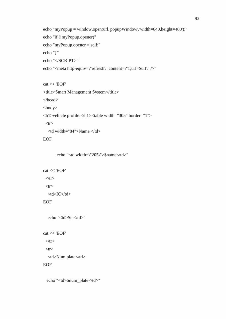
93
echo "myPopup = window.open(url,'popupWindow','width=640,height=480');"
echo "if (!myPopup.opener)"
echo "myPopup.opener = self;"
echo ""
echo "</SCRIPT>"
echo "<meta http-equiv=\"refresh\" content=\"1;url=$url\" />"
cat << 'EOF'
<title>Smart Management System</title>
</head>
<body>
<h1>vehicle profile:</h1><table width="305" border="1">
<tr>
<td width="84">Name </td>
EOF
echo "<td width=\"205\">$name</td>"
cat << 'EOF'
</tr>
<tr>
<td>IC</td>
EOF
echo "<td>$ic</td>"
cat << 'EOF'
</tr>
<tr>
<td>Num plate</td>
EOF
echo "<td>$num_plate</td>"

94
cat << 'EOF'
</tr>
<tr>
<td>H/P</td>
EOF
echo "<td>$h_phone</td>"
cat << 'EOF'
</tr>
</table>
<p> </p>
<h1>Battery monitoring status:</h1>
EOF
#power management system starts over here
info=`cat $HOME/awhttpd/default/evteam/web.txt`
info_line=`cat $HOME/awhttpd/default/evteam/web.txt | wc -l`
for((i=0;i<$info_line;i++))
do
#tmp= `expr $i +1`
(( tmp = i + 1))
TEMP[$i]=` echo -e "$info" | cut -d$'\x0a' -f$tmp`
done
#disp test
#for((i=0;i<$info_line;i++))
#do
# echo "temp_data[$i]: $TEMP[$i]"
#done
# Table Generation
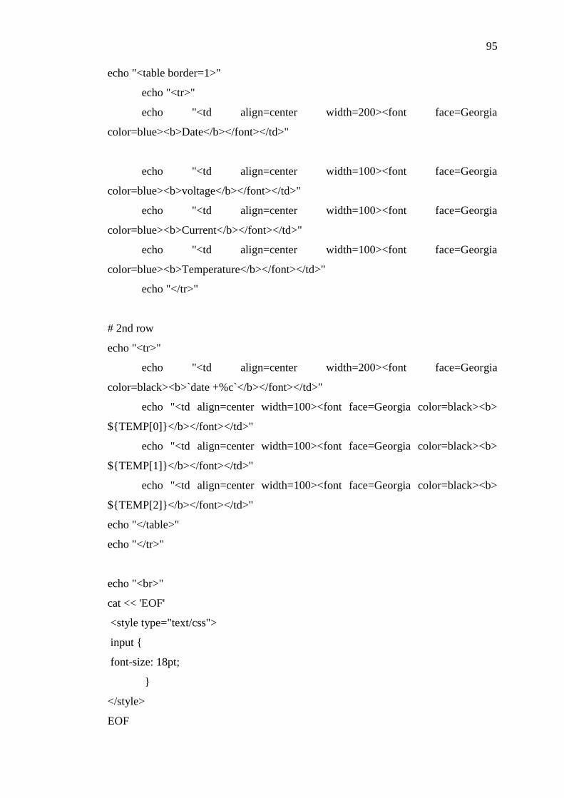
95
echo "<table border=1>"
echo "<tr>"
echo "<td align=center width=200><font face=Georgia
color=blue><b>Date</b></font></td>"
echo "<td align=center width=100><font face=Georgia
color=blue><b>voltage</b></font></td>"
echo "<td align=center width=100><font face=Georgia
color=blue><b>Current</b></font></td>"
echo "<td align=center width=100><font face=Georgia
color=blue><b>Temperature</b></font></td>"
echo "</tr>"
# 2nd row
echo "<tr>"
echo "<td align=center width=200><font face=Georgia
color=black><b>`date +%c`</b></font></td>"
echo "<td align=center width=100><font face=Georgia color=black><b>
$TEMP[0]</b></font></td>"
echo "<td align=center width=100><font face=Georgia color=black><b>
$TEMP[1]</b></font></td>"
echo "<td align=center width=100><font face=Georgia color=black><b>
$TEMP[2]</b></font></td>"
echo "</table>"
echo "</tr>"
echo "<br>"
cat << 'EOF'
<style type="text/css">
input
font-size: 18pt;
</style>
EOF

96
echo "</body>"
echo "<FORM>"
echo "<INPUT TYPE=\"BUTTON\" VALUE=\"vehicle past status\"
onClick=\"openPopup('ev_1.cgi')\">"
echo "</FORM>"
echo "</html>"
#Author: bkcheah
#Module: obtain vehicle past records
#File name: ev_1.cgi
# File location: /home/bkcheah/awhttpd/default/evteam
#!/bin/bash
# author: bkcheah
echo "Content-type: text/html"
echo -e "\r\n"
#define absolute path
path="$HOME/awhttpd/default/evteam/intel.txt"
url="http://192.168.0.102:8384/evteam/ev_1.cgi"
cat << 'EOF'
<!DOCTYPE html PUBLIC "-//W3C//DTD XHTML 1.0 Transitional//EN"
"http://www.w3.org/TR/xhtml1/DTD/xhtml1-transitional.dtd">
<html xmlns="http://www.w3.org/1999/xhtml">
<head>
<title>Untitled Document</title>
</head>
<body>

97
<h1>Vehicle record:</h1>
<FORM NAME="myform" action="ev_1.cgi" method="get">
EOF
#control element
#echo "<br>"
#echo "\$@ = $@"
#echo "<br>"
#echo "\$? = $?"
#echo "<br>"
#echo "QUERY_STRING = $QUERY_STRING"
#echo "<br>"
#echo "QUERY_STRING_POST = $QUERY_STRING_POST"
#echo "<br>"
#echo "REMOTE_ADDR = $REMOTE_ADDR"
#echo "<br>"
#echo "HTTP_HOST = $HTTP_HOST"
#echo "<br>"
#echo "SERVER_PORT = $SERVER_PORT"
#echo "<br>"
#echo "SCRIPT_NAME = $SCRIPT_NAME"
#echo "<br>"
#echo "REQUEST_METHOD = $REQUEST_METHOD"
#echo "<br>"
#echo "CONTENT_LENGTH = $CONTENT_LENGTH"
#echo "<br>"
rows=`cat $path| wc -l`
data=`cat $path`
#num_rows=$((`echo $data|sed 's/[^&]//g'|wc -m`-1)) #And Counter
#(( num_data = num_rows + rows ))
((t_row=rows/4))

98
for((i=0;i<$rows;i++))
do
tmp=`expr $i + 1`
TEMP[$i]=` echo -e "$data" | cut -d$'\x0a' -f$tmp`
#TEMP[$i]=` echo -e "$data" | cut -d$\& -f$tmp`
done
#for((i=0;i<$rows;i++))
#do
# echo "LINE $TEMP[$i]"
# echo "<br>"
#done
echo "<table border=1>"
echo "<tr>"
echo "<td align=center width=100><font face=Georgia color=blue><b>check to
delete</b></font></td>"
echo "<td align=center width=100><font face=Georgia
color=blue><b>Date</b></font></td>"
echo "<td align=center width=300><font face=Georgia
color=blue><b>Name</b></font></td>"
echo "<td align=center width=300><font face=Georgia color=blue><b>Company's
name</b></font></td>"
echo "<td align=center width=500><font face=Georgia
color=blue><b>Comment</b></font></td>"
echo "</tr>"
new1=3
tmp1=0
for((i=0;i<$t_row;i++))
do
echo "<tr>"

99
echo "<td><input type=\"checkbox\" name=\"checkbox\"
value=\"$i\"></td>"
for ((j=$tmp1; j<=$new1; j++))
do
if [ "$#TEMP[$j]" -ne 0 ]; then
echo "<td align=center><font face=\"Courier New\"><b>
"$TEMP[$j]" </b></font></td>"
else
echo "<td><font face=\"Courier
New\"><b>"""$TEMP[$j]"<br>""</b></font></td>"
fi
done
(( tmp1+=4 ))
(( new1+=4 ))
echo "</tr>"
done
echo "</table>"
##### additional feature
num=$((`echo $QUERY_STRING|sed 's/[^&]//g'|wc -m`-1)) #And Counter
data_num=`expr $num + 1`
#----------------------------cut the '&' and '=' --------------------
for ((i=0; i<$data_num; i++))
do
tmp0=`expr $i + 1`
TE[$i]=`echo "$QUERY_STRING" | cut -d\& -f$tmp0 `
done

100
for ((i=0; i<$data_num; i++))
do
tmp0=`expr $i \* 2`
for ((j=1; j<3; j++))
do
data_arr[$tmp0]=`echo "$TE[$i]" | cut -d= -f$j`
tmp0=`expr $tmp0 + 1`
done
done
k=0
for ((i=0; i<$data_num; i++))
do
let j=2*i+1
arr[$k]="$data_arr[$j]"
let k++
done
## disp control logics ##
#echo "<br>"
#for((i=0;i<$k;i++))
#do
# echo "$arr[$i]"
# echo "<br>"
#done
########################
flag2=1
for ((i=0; i<$t_row; i++))
do
for ((k=0; k<$data_num && $flag2; k++))
do

101
if [ "$arr[$k]" = "$i" ]; then
#echo "vince : $arr[$k], $i <br>"
flag=1
flag2=0
else
#echo "test: $arr[$k], $i <br>"
flag=0
fi
done
flag2=1
if [ $flag -eq 1 ]; then
#echo "no print for $i "
:
else
#echo "print for $i"
#temp=`expr $i + 4`
a[$n]=$i
#b[$n]=$temp
let n++
fi
done
echo "<br>"
################################
#for((i=0;i<$n;i++))
#do
# echo "[!!!] $b[$i] | $a[$i]"
# echo "<br>"
#done
first="$arr[0]"
if [ $#first -ne 0 ]; then
: > $path

102
for((i=0;i<$n;i++))
do
temp=$a[$i]
(( low = 4*temp ))
(( upper = low+3 ))
#echo "$low | $upper"
#echo "<br>"
for((j=$low;j<=$upper;j++))
do
echo "$TEMP[$j]" >> $path
done
done
echo "<meta http-equiv=refresh content=\"0;url=$url\">"
fi
#############################
echo "<br>"
cat << 'EOF'
<style>
input
font-size: 18pt;
</style>
<INPUT TYPE="submit" VALUE="Delete" style="height: 3em; width: 5em" >
</form>
<br>
<form method="link" action="ev_2.cgi">
<input type="submit" value="Add remark to vehicle record">
</form>
</body>
</html>
EOF

103
#Author: bkcheah
#Module: Inserting vehicle records
#File name: ev_2.cgi
# File location: /home/bkcheah/awhttpd/default/evteam
#!/bin/bash
echo "Content-type: text/html"
echo -e "\r\n"
path=$HOME/awhttpd/default/evteam/intel.txt
#echo "<br>"
#echo "\$@ = $@"
#echo "<br>"
#echo "\$? = $?"
#echo "<br>"
#echo "QUERY_STRING = $QUERY_STRING"
#echo "<br>"
#echo "QUERY_STRING_POST = $QUERY_STRING_POST"
#echo "<br>"
#echo "REMOTE_ADDR = $REMOTE_ADDR"
#echo "<br>"
#echo "HTTP_HOST = $HTTP_HOST"
#echo "<br>"
#echo "SERVER_PORT = $SERVER_PORT"
#echo "<br>"
#echo "SCRIPT_NAME = $SCRIPT_NAME"
#echo "<br>"
#echo "REQUEST_METHOD = $REQUEST_METHOD"
#echo "<br>"
#echo "CONTENT_LENGTH = $CONTENT_LENGTH"
#echo "<br>"
cat << 'EOF

104
<html>
<head>
<SCRIPT LANGUAGE="JavaScript">
//controlling textbox
function textCounter(field,cntfield,maxlimit)
if (field.value.length > maxlimit)
field.value = field.value.substring(0, maxlimit);
else
cntfield.value = maxlimit - field.value.length;
a
function check (a)
if ( a != 0 )
var message="Error message";
var count="\nplease fill in all the text fields";
display=message+count
alert(display);
function call()
alert("File Successfully written");
</script>
<meta http-equiv="Content-Type" content="text/html; charset=windows-1252" />

105
<title>vehicle content</title></head>
<body>
<script type=text/javascript>
check(0,0,0,0);
</script>
<script type=text/javascript>
file(0,);
</script>
<h1>vehicle profile</h1>
EOF
string_length=$#QUERY_STRING
num=$((`echo $QUERY_STRING|sed 's/[^&]//g'|wc -m`-1)) #And Counter
data_num=`expr $num + 1`
#cut the '&' and '='
for ((i=0; i<$data_num; i++))
do
tmp0=`expr $i + 1`
TEMP[$i]=`echo "$QUERY_STRING" | cut -d\& -f$tmp0 `
done
for ((i=0; i<$data_num; i++))
do
tmp0=`expr $i \* 2`
for ((j=1; j<3; j++))
do
data_arr[$tmp0]=`echo "$TEMP[$i]" | cut -d= -f$j`
tmp0=`expr $tmp0 + 1`
done
done

106
#----------display the result --------------------------------
#for ((i=0; i<`expr $data_num \* 2`; i++))
#do
# echo "<br>"
# echo "vince_test_value: $data_arr[$i]"
#done
#--------------------------------------------------------------
(( total=$data_num*2 ))
counter=0
if [ $string_length -ne 0 ]; then
for ((i=1; i<=3; i++))
do
(( j=2*i+1 ))
temp="$data_arr[$j]"
if [ $#temp -eq 0 ]; then
let counter++
fi
done
fi
echo "<script type="text/javascript">"
echo "check($counter);"
echo "</script>"
#condition to be check
t_name="$data_arr[1]"
t_name=`echo $t_name//+/ `
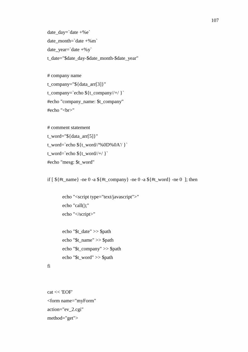
107
date_day=`date +%e`
date_month=`date +%m`
date_year=`date +%y`
t_date="$date_day-$date_month-$date_year"
# company name
t_company="$data_arr[3]"
t_company=`echo $t_company//+/ `
#echo "company_name: $t_company"
#echo "<br>"
# comment statement
t_word="$data_arr[5]"
t_word=`echo $t_word//'%0D%0A'/ `
t_word=`echo $t_word//+/ `
#echo "mesg: $t_word"
if [ $#t_name -ne 0 -a $#t_company -ne 0 -a $#t_word -ne 0 ]; then
echo "<script type="text/javascript">"
echo "call();"
echo "</script>"
echo "$t_date" >> $path
echo "$t_name" >> $path
echo "$t_company" >> $path
echo "$t_word" >> $path
fi
cat << 'EOF'
<form name="myForm"
action="ev_2.cgi"
method="get">

108
<table width="312" border="0">
<tr>
<th width="83" scope="row">Name:</th>
<td width="219">
<input type="text" name="textfield1" value="" />
</td>
</tr>
</table>
<table border="0">
<tr>
<th scope="row">Company's name:</th>
<td ><input type="text" name="textfield2" /></td>
</tr>
</table>
<table width="312" border="0">
<tr>
<th scope="row">Comment:</th>
<td width="240" rowspan="2"><textarea name="message1" wrap="physical"
cols="28" rows="5"
onKeyDown="textCounter(document.myForm.message1,document.myForm.remLen
1,125)"
onKeyUp="textCounter(document.myForm.message1,document.myForm.remLen1,1
25)"></textarea>
<br>
<input readonly type="text" name="remLen1" size="3" maxlength="3"
value="125">
characters left <br></td>
</tr>
<tr>
<th width="89" scope="row"><p> </p>
<p> </p></th>
</tr>
</table>

109
<table border="0">
<tr>
<th scope="row">Dated Event:</th>
EOF
echo "<th scope=\"row\">$t_date</th>"
cat << 'EOF'
</tr>
</table>
<br>
<br>
<style type="text/css">
input
font-size: 18pt;
</style>
<input type="Submit" name="Submit" value="Submit">
</form>
<form action="ev_1.cgi">
<input type="Submit" value="back to the vehicle record ">
</form>
</body>
</html>
EOF