Embed Size (px)
Citation preview
ELECTRIC VEHICLEINFRASTRUCTURE
INSTALLATION GUIDE
March 1999Edition
Pacific Gas and Electric Company
Electric Vehicle Infrastructure In-stallation Guide
Electrical ContractorsCity and County Building Inspectors
EVSE InstallersArchitects and Engineers
Pacific Gas and Electric Company Employees
March 1999
1999 Edition
The Electric Vehicle Infrastructure Installation Guide is an over-view of policies, requirements and codes for establishing electric serv-ice and for the installation of electric vehicle charging equipment.
In addition to the utility requirements, local or state officials maystipulate additional provisions for the installation of equipment andmaterials which are in their authorized areas of responsibility and juris-diction.
Should you have any questions regarding this book, please con-tact the Clean Air Transportation Department of Pacific Gas and Elec-tric Company at 800 684-4648.
Final customer electric service and meter installation require-ments are subject to prior Pacific Gas and Electric Company reviewand approval
Copyright � 1999by Pacific Gas and Electric Company
All rights reserved
No part of this book may be reproduced in any form,whatsoever, without written permission from Pacific Gas andElectric Company.
Pacific Gas and Electric CompanyClean Air Transportation Department
Mail Code H28LP.O. Box 770000
San Francisco, CA 94177
Produced byClean Air Transportation Department
TABLE OF CONTENTSPage
1. Introduction.............................................................................................................................1A. EV Infrastructure Essentials................................................................................................1B. Information Resources.........................................................................................................2
2. EV Charging Essentials...........................................................................................................3A. Rules and Regulations Governing EV Infrastructure Installations.........................................3
1. The National Electrical Code (NEC).................................................................................32. The California Electrical Code (CEC)...............................................................................43. Local Codes and Ordinances.............................................................................................44. UL Listing........................................................................................................................45. Installation Plans...............................................................................................................56. Equipment Certification....................................................................................................5
B. EV Charging Levels............................................................................................................51. Level 1 Charging..............................................................................................................52. Level 2 Charging..............................................................................................................63. Level 3 Charging..............................................................................................................6
C. Charger Technologies: Conductive and Inductive................................................................61. Conductive Technologies..................................................................................................62. Inductive Technologies.....................................................................................................7
D. Charging Equipment Currently Available.............................................................................7E. PG&E EV Rates..................................................................................................................9
3. Code Requirements for Installing EVSE................................................................................12A. EVSE Used in Level 1 Installations...................................................................................12B. EVSE Used in Level 2 Installations...................................................................................13C. Installations Where Ventilation is Required........................................................................14D. Codes Governing EVSE Siting..........................................................................................15E. Installations Located in Flood Zones..................................................................................16F. Required Signage...............................................................................................................16G. Lighting Recommendations...............................................................................................17H. Disable Access..................................................................................................................18
4. EV Charging in Single Family Residences..............................................................................19A. Step 1: Determine the Charging and Battery Types............................................................19B. Step 2: EV Utility Rates and Meter Options......................................................................19C. Step 3: Determine the Home’s Electrical Capacity.............................................................19D. Step 4: Determine EVSE Placement..................................................................................19
1. Safety Issues in Enclosed Garages..................................................................................202. Extending Electrical Service...........................................................................................203. Outdoor Charging ..........................................................................................................20
E. Step 5: Drawing Up the Installation Plans..........................................................................20F. Step 6: Obtaining Permits, Performing the Installation, and Conducting a
Site Inspection.....................................................................................................21
G. Other Issues Pertaining to Single Family Residences..........................................................211. Insurance........................................................................................................................212. Costs..............................................................................................................................21
H. Single-Family Residence EVSE Installation Checklist 23I. Issues Related to Installations in Multifamily Residences.....................................................25
1. Ownership of EVSE.......................................................................................................252. Apartments.....................................................................................................................253. Condominiums and Townhouses.....................................................................................254. Metering Arrangements..................................................................................................255. Electrical Capacity..........................................................................................................266. Insurance........................................................................................................................267. Costs..............................................................................................................................26
5. EV Charging at Fleet Facilities...............................................................................................27A. Site Planning.....................................................................................................................27
1. Number of EVs and Chargers.........................................................................................272. Convenience...................................................................................................................283. Cable Management.........................................................................................................294. Ventilation Needs...........................................................................................................295. Battery Operating and Charging Temperature Limits......................................................296. Standing Water and Irrigation.........................................................................................297. Curbs, Wheel Stops, and Setbacks..................................................................................298. Vandalism......................................................................................................................299. Signs..............................................................................................................................2910. Disabled Access............................................................................................................29
B. Checklist for Fleet Facility EVSE Siting.............................................................................30C. Engineering and Construction............................................................................................30D. Charging Equipment..........................................................................................................31E. Fleet Recharge Management Systems................................................................................31F. Metering and Billing Systems.............................................................................................32G. Electrical Service...............................................................................................................33H. Electric Rates....................................................................................................................33I. Site Installation Plan...........................................................................................................33J. Building Permits.................................................................................................................34K. Costs.................................................................................................................................34L. Checklist for Vehicle Fleet Charging..................................................................................36
6. Public Access and Commercial Charging Installations............................................................39A. Local Codes and Regulations.............................................................................................39B. Payment of Charging Services...........................................................................................39C. Types of Chargers and Level of Charging..........................................................................39D. EVSE Siting Decisions......................................................................................................39E. Electrical Service Adequacy...............................................................................................40F. Electric Rates.....................................................................................................................40G. Prevention of Vandalism....................................................................................................40H. Lighting............................................................................................................................41I. Creating the Site Plan .........................................................................................................41

J. Installation Costs................................................................................................................41K. Checklist for Public Access and Commercial Charging Installations...................................41
Appendix A. Public Charging Locations Currently in Operation.................................................43L. Inductive Sites...................................................................................................................43M. Conductive Charging Sites................................................................................................44
Appendix B. Building Code Contacts in Major Cities.................................................................46Appendix C. Glossary of EV Terms...........................................................................................47Appendix D. References............................................................................................................50

. TABLE OF FIGURES
Figure 1: Typical Residential EV Charging Infrastructure...............................................................2Figure 2: Conductive and Inductive Level 2 Connectors................................................................7Figure 3: Options for Installing Dual Meter Adapters (Where Allowable).......................................11Figure 4: Typical Signs Used with EVSE and Charging Locations.................................................16Figure 5: Typical Parking layout for Disable access........................................................................18Figure 6: Sample Residential EV Infrastructure Plan......................................................................22

EV Infrastructure Installation Guide 1
1. INTRODUCTION
The introduction of electric vehicles (EVs) in Northern California brings a challenging set of plan-ning, regulatory, and cost issues. Because EVs require a unique infrastructure—including spe-cialized charging equipment and adequate electric service—most users, as well as infrastructureinstallers and PG&E staff, are not familiar with charging basics. This guide provides the necessaryinformation all users, installers, and PG&E need to better handle the task of installing the appro-priate equipment for residential and fleet EV customers.
The guide’s introduction defines key terms and responsibilities, and gives other sources of infor-mation. Chapter 2 discusses the safety codes governing EV charging equipment, electrical re-quirements, equipment options, and PG&E rates for EVs. Chapter 3 details the electrical andbuilding code requirements that apply to all installers and users of electric vehicle supply equip-ment (EVSE). The remaining chapters discuss the special needs of the different classes of EV us-ers: homeowners (including multifamily residences), fleet facilities, and public access andcommercial charging facilities.
For fleet users, the Energy Policy Act of 1992 (EPAct) requires fuel providers to include alterna-tive fuel vehicles (AFVs) in their replacement vehicle purchases beginning in 1996. PG&E hasopted to use EVs to meet part of this requirement. EPAct also sets guidelines for federal, state,local, and private fleets to include AFVs when purchasing replacement vehicles, and many ofthese organizations also plan to buy EVs. As a result, the installation of EVSE has become animportant issue to many fleet managers today.
For residential customers, infrastructure issues are less complex in terms of siting, equipment se-lection, and load management. In addition, EV manufacturers provide ample information and as-sistance concerning EVSE placement and installation. However, municipalities in PG&E’sservice territory treat metering issues differently. This guide addresses the practices in a few citiesand provides names of relevant code officials.
A. EV Infrastructure EssentialsEV infrastructure is comprised of the following components:
x EVSE, including a charger, cable, and connector
x Premises wiring that runs from the customer meter to the EVSE
x Electrical service, including PG&E power lines and the customer meter
PG&E provides installation advice and assistance (call PG&E’s Clean Air Transportation Hotlineat 800-684-4648) but the EV owner is ultimately responsible for the installation and operation ofthe EVSE, as well as for any upgrades or improvements to the premises wiring. EV owners mustobtain the appropriate building permits and ensure that a qualified licensed contractor or electricianperforms the installation. EV dealerships offer assistance in finding contractors for these installation
EV Infrastructure Installation Guide 2
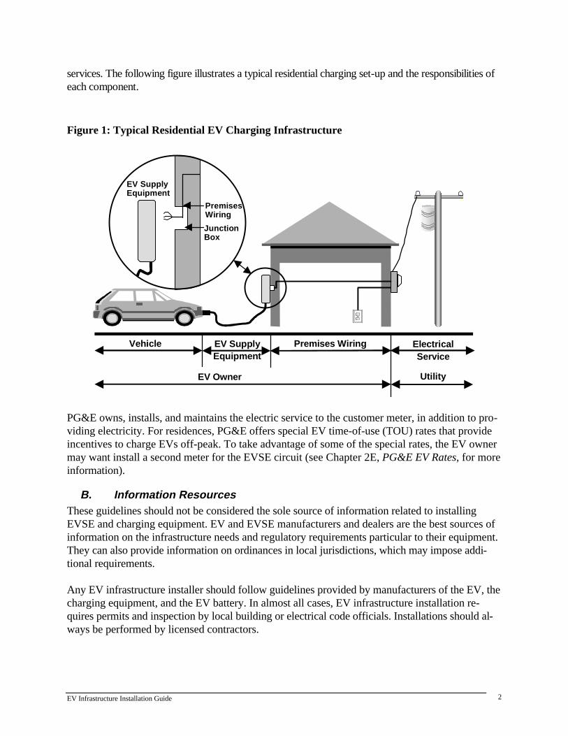
services. The following figure illustrates a typical residential charging set-up and the responsibilities ofeach component.
Figure 1: Typical Residential EV Charging Infrastructure
EV Owner
PremisesWiring
JunctionBox
EV SupplyEquipment
Utility
Vehicle EV SupplyEquipment
Premises Wiring ElectricalService
PG&E owns, installs, and maintains the electric service to the customer meter, in addition to pro-viding electricity. For residences, PG&E offers special EV time-of-use (TOU) rates that provideincentives to charge EVs off-peak. To take advantage of some of the special rates, the EV ownermay want install a second meter for the EVSE circuit (see Chapter 2E, PG&E EV Rates, for moreinformation).
B. Information ResourcesThese guidelines should not be considered the sole source of information related to installingEVSE and charging equipment. EV and EVSE manufacturers and dealers are the best sources ofinformation on the infrastructure needs and regulatory requirements particular to their equipment.They can also provide information on ordinances in local jurisdictions, which may impose addi-tional requirements.
Any EV infrastructure installer should follow guidelines provided by manufacturers of the EV, thecharging equipment, and the EV battery. In almost all cases, EV infrastructure installation re-quires permits and inspection by local building or electrical code officials. Installations should al-ways be performed by licensed contractors.

EV Infrastructure Installation Guide 3
2. EV CHARGING ESSENTIALS
The codes, standards, and ordinances governing EVSE design, manufacturing, and installationmake EV charging safe. The person performing the charging is protected against electrical shockthrough the use of protection systems. Nationally recognized testing laboratories such as the Un-derwriters Laboratory (UL), have approved and listed EV charging components to ensure theirdurability and safety.
The following is a list of standard EVSE safety features:
x An EV will not start if it is still plugged into the charger
x Before the charger can be disconnected, the cable must de-energized
x The vehicle inlet is de-energized until the driver attaches the unique connector to the vehicle
x The EV connector cannot be used with other appliances
x Monitors and a ground-fault circuit interrupt (GFCI) shut down the electricity supply if theysense a potential problem
x For the few battery types that emit potentially explosive gases, building codes require ventila-tion to eliminate risks.
Any variation from relevant building codes and regulations can create a potential hazard. Abusingthe equipment can also lead to trouble. All EV owners and EVSE installers must note that abuilding permit is required for EVSE installations and should adhere strictly to the applicablecodes, standards, and ordinances.
A. Rules and Regulations Governing EV Infrastructure InstallationsIn most circumstances, local building officials will not issue permits for installing EVSE withoutfirst seeing plans showing compliance with applicable codes and ordinances. Compliance with lo-cal and state regulations is necessary to pass the building inspector’s post-installation inspection.California and federal codes that regulate charger installation are described below.
1. The National Electrical Code (NEC)The National Fire Protection Association’s National Electrical Code (NEC) sets standards forelectrical construction and operation. The NFPA revises and publishes a new National ElectricalCode Handbook every three years. The 1999 NEC update covers EV charger installation issues inChapter 6, Article 625.
The 1999 NEC update has added new language to two sections of Article 625. Article 625-22calls for personnel protection systems for EV charging systems to replace ground-fault currentinterrupter devices to protect from shock. Article 625-29(d)(3) provides an alternate method fordetermining indoor ventilation levels.
EV Infrastructure Installation Guide 4
2. The California Electrical Code (CEC)The 1998 California Electrical Code (CEC), administered by the California Building StandardsCommission and the state Fire Marshall's office, mirrors the NEC. Variations with the NEC werereconciled in 1998.
Chapter 3 provides a summary of the CEC.
3. Local Codes and OrdinancesLocal jurisdictions can either adopt the national or state codes, or enact regulations that are morestringent. Some California counties, such as Sacramento County, passed ordinances requiringconduits for EV charging in new residential construction. These ordinances will save owners timeand money when they want to install EVSE.
Some of the larger cities in Northern California have regulations prohibiting residences from in-stalling dual meter adapters. These adapters are necessary to take advantage of certain specialtime-of-use rates (see Chapter 2E), which are particularly important to EV users.
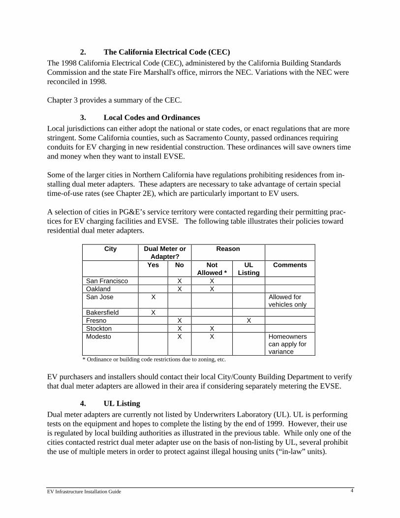
A selection of cities in PG&E’s service territory were contacted regarding their permitting prac-tices for EV charging facilities and EVSE. The following table illustrates their policies towardresidential dual meter adapters.
City Dual Meter orAdapter?
Reason
Yes No NotAllowed *
ULListing
Comments
San Francisco X XOakland X XSan Jose X Allowed for
vehicles onlyBakersfield XFresno X XStockton X XModesto X X Homeowners
can apply forvariance
* Ordinance or building code restrictions due to zoning, etc.
EV purchasers and installers should contact their local City/County Building Department to verifythat dual meter adapters are allowed in their area if considering separately metering the EVSE.
4. UL ListingDual meter adapters are currently not listed by Underwriters Laboratory (UL). UL is performingtests on the equipment and hopes to complete the listing by the end of 1999. However, their useis regulated by local building authorities as illustrated in the previous table. While only one of thecities contacted restrict dual meter adapter use on the basis of non-listing by UL, several prohibitthe use of multiple meters in order to protect against illegal housing units (“in-law” units).
EV Infrastructure Installation Guide 5
5. Installation PlansMost local jurisdictions require EV owners to submit building or electrical plans as part of thepermit process. These plans can include:
x A plan or one-line diagram showing the service panel schedule and branch circuit location
x A diagram describing the ventilation system, including location of the EVSE, air inlet, and ex-haust fan may be required when EV batteries requiring ventilation are used.
6. Equipment CertificationThe local building inspector will verify that components are approved, or UL-listed and labeled.According to NEC, approved means “acceptable to the authority having jurisdiction.”
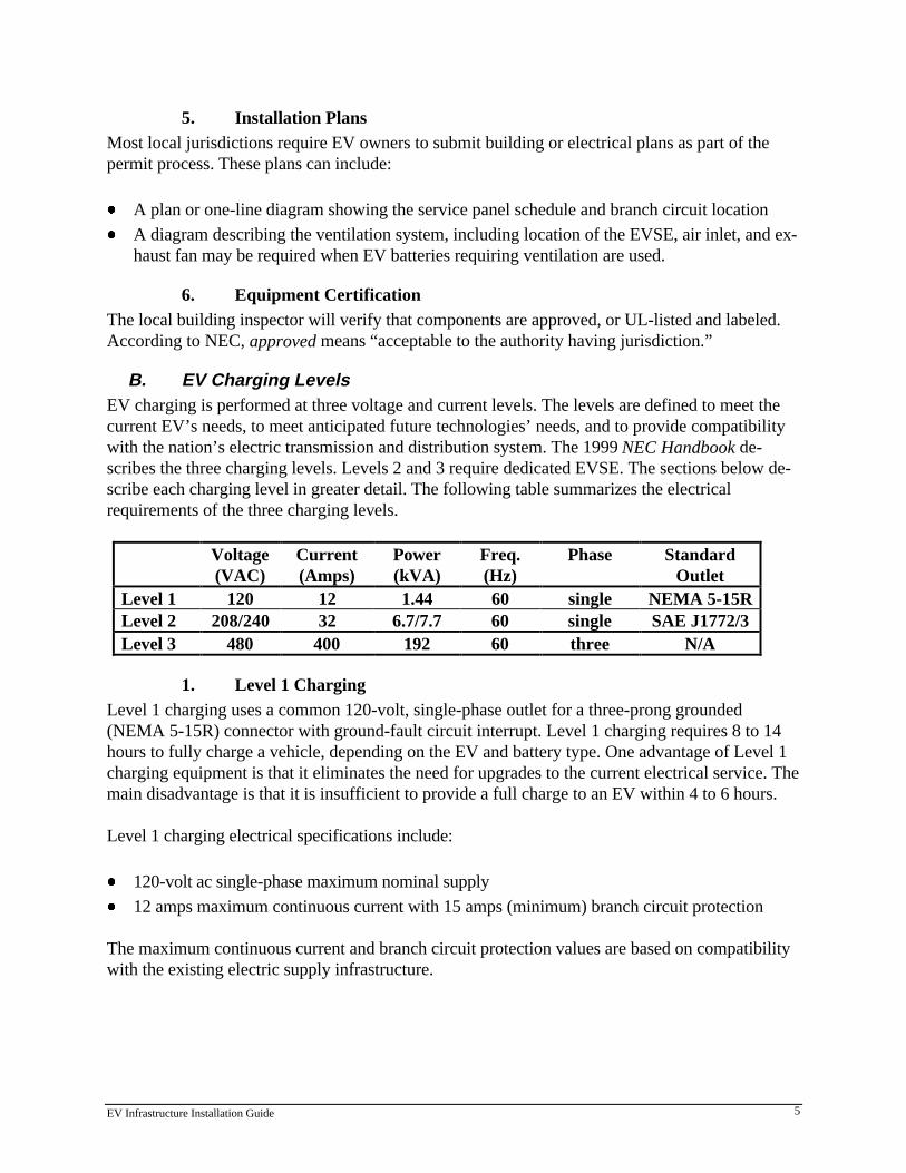
B. EV Charging LevelsEV charging is performed at three voltage and current levels. The levels are defined to meet thecurrent EV’s needs, to meet anticipated future technologies’ needs, and to provide compatibilitywith the nation’s electric transmission and distribution system. The 1999 NEC Handbook de-scribes the three charging levels. Levels 2 and 3 require dedicated EVSE. The sections below de-scribe each charging level in greater detail. The following table summarizes the electricalrequirements of the three charging levels.
Voltage(VAC)
Current(Amps)
Power(kVA)
Freq.(Hz)
Phase StandardOutlet
Level 1 120 12 1.44 60 single NEMA 5-15RLevel 2 208/240 32 6.7/7.7 60 single SAE J1772/3Level 3 480 400 192 60 three N/A
1. Level 1 ChargingLevel 1 charging uses a common 120-volt, single-phase outlet for a three-prong grounded(NEMA 5-15R) connector with ground-fault circuit interrupt. Level 1 charging requires 8 to 14hours to fully charge a vehicle, depending on the EV and battery type. One advantage of Level 1charging equipment is that it eliminates the need for upgrades to the current electrical service. Themain disadvantage is that it is insufficient to provide a full charge to an EV within 4 to 6 hours.
Level 1 charging electrical specifications include:
x 120-volt ac single-phase maximum nominal supply
x 12 amps maximum continuous current with 15 amps (minimum) branch circuit protection
The maximum continuous current and branch circuit protection values are based on compatibilitywith the existing electric supply infrastructure.

EV Infrastructure Installation Guide 6
2. Level 2 ChargingWhen using Level 2 charging, an EV can be charged in 4 to 6 hours, depending on the EV, bat-tery type, and capacity.
Level 2 charging electrical specifications include:
x 208-240 volts ac single-phase maximum nominal supply
x 32 amps maximum continuous current with 40 amps branch circuit protection
Other required features for Level 2 charging include grounding or electrical isolation, personnelprotection from shock, a no-load make/break interlock, and a safety breakaway for the cable andconnector.
3. Level 3 ChargingLevel 3, or fast charging, requires high levels of voltage and current to replenish more than half ofan EV’s battery capacity in as quickly as ten minutes. Tests of Level 3 charging have taken placeand a commercial charger was recently made available. However, there are no public chargingsites using Level 3 charging in PG&E’s service territory as of March 1999.
Level 3 chargers use a 480-volt ac, 400-amp, three-phase electrical service and require the samesafety features as Level 2 EVSE.
C. Charger Technologies: Conductive and InductiveCurrently there are two technologies being used to connect EVs to the EVSE: conductive andinductive. Both are available for all levels of charging.
EVs will only use one of these technologies since they are incompatible. A vehicle using one tech-nology typically cannot be connected to a charger with the other technology because they employdifferent connectors. Each technology has its strengths and weaknesses as listed in the followingtable:
Issue Inductive ConductiveSafety No difference No differenceEnergy Efficiency Not as efficient as conduc-
tive chargingMore efficient
Cost Complexity of system makesit more expensive
Simpler system makes it lessexpensive
1. Conductive TechnologiesConductive charging uses physically connecting contacts, similar to methods used by commonappliances. It is the method used by most on-board chargers, or systems that place the chargingcircuitry and control on the vehicle. The connector for these systems is usually a butt-type con-nector.

EV Infrastructure Installation Guide 7
Some off-board chargers, or systems that place the charging circuitry and controls off-board thevehicle in a charging stand, also use conductive coupling. In this case, the charger communicateswith the battery and vehicle electronics over the communications wiring in the connector.
2. Inductive TechnologiesInductive charging systems transfer ac power by magnetically coupling a primary winding on thesupply side to a secondary winding on the vehicle side. Current flows through the primary induc-tor coil, or paddle, and the resulting magnetic flux induces an alternating current through themagnetic field and across the secondary coil, completing the circuit. The ac current is convertedto dc for storage in the vehicle battery.
Inductive chargers keep most of the charging circuitry and controls in an off-board chargingstand, and communicate with the battery and vehicle electronics via infrared or radio frequencies.
Figure 2: Conductive and Inductive Level 2 Connectors
D. Charging Equipment Currently AvailableAs of March 1999, the following EVSE are available in PG&E’s service territory (listed bymanufacturer):
EV Infrastructure Installation Guide 8
x AVCON Product Name: EV Power Pak Charging Type: Conductive Charging Level: Level II Price: $295 Contact: Kristine Todryke, AVCON - 800/433-7642 Comments: Price includes shipping and handling
x Aerovironment Product Name: PosiCharge Charging Type: Conductive Charging Level: Level III (fast charge) Price: Model PC 60100 (60 kW) - $40,000 available with 240v and 480v utility connections;(120 kW) - $80,000 available with 240v and 480v utility connections Contact: Jon Bertolino, Sacramento Municipal Utility District (SMUD), 916/732-6980 forNorthern California and Nevada; Marc Cortez, Aerovironment, 626/357-9983 x311 for SouthernCalifornia and Arizona Comments: The 60 kW unit has a UL listing but the 120 kW unit does not. Aerovironment alsooffers battery management systems (BMS) for OEM electric vehicle and EV conversions so theycan use PosiCharge. The cost of a BMS unit starts at $2,200.
x Electric Vehicle Infrastructure, Inc. (EVI) Product Name: Model ICS-200B Charging Type: Conductive Charging Level: Level II Price: Model ICS-200B, single outlet, wall mounted - $1,800; Model ICS-200B, single outletwith pedestal - $2,205; Model ICS-200B dual outlets, with pedestal - $4,120 Contact: Edison EV - 888/890-GOEV or ETEC - 888/383-2387 Comments: EVI ‘s chargers can come with additional options
x General Motors ATV Product Name: Magne Charge Charging Type: Inductive Charging Level: Level II Price: Wall mounted unit - $1,995; Floor/pedestal unit - $3,285 Contact: Edison EV - 888/890-GOEV Comments: Chargers are 7.5 kW. GM ATV has a fast charger in demonstration but not availablefor purchase.

EV Infrastructure Installation Guide 9
x Lockheed Martin Product Name: 14.4 kW Conductive Charger Station Charging Type: Conductive Charging Level: Level II Price: Not available. See comments below Contact: Edison EV - 888/890-GOEV or ETEC - 888/383-2387 Comments: The charger is included with the purchase of Chrysler’s EPIC minivan only and notavailable for general purchase.
x Norvik Product Name: Minit Charger Charging Type: Conductive Charging Level: Level II and Level III (fast charge) Price: Ranges from $35,000 for a 35 kW charger to $125,000 for the 250 kW fast charger. Contact: Janet Vogt, Norvik Traction, Inc., 905/828-7700 Comments: Price varies depending on model features
x SCI SystemsProduct Name: Stylized Wall Mount; PedestalCharging Type: ConductiveCharging Level: Level IIPrice: Stylized Wall Mount, single outlet - $1,800; Pedestal, single outlet - $2,695; Pedestal, dualoutlets - $3,995Contact: ETEC - 888/383-2387Comments: Custom configurations are available
E. PG&E EV RatesPG&E offers special rates to encourage EV market development and electricity use during night-time, off-peak hours when the utility has surplus distribution capacity. EV charging is a naturalmatch for time-of-use rates since most EV users—in both residences and fleets—find that themost convenient (and sometimes the only) time to charge their vehicle is overnight.
There are two options available to homeowners seeking to use TOU rates. First, the entirehouse—including the EVSE—can be metered under the special EV rates (see below). An alterna-tive is to meter the EVSE separately from the rest of the house. To accommodate this, a secondmeter panel or a special dual-meter adapter is required. The adapter may not work in all residen-tial installations. In such cases, the customer may have to pay a licensed electrician to install asecond meter conforming to local jurisdiction or utility requirements. When the customer has themeter installed, requirements for city permits and inspections apply (see section on local regula-tions).
PG&E’s rate schedule E9 is based on time-of-use and season. Residential customers have the op-tion of selecting one of two rates from rate schedule E9, depending on their meter set-up. RateE9A applies to electricity used in the entire residence, including the EV and does not require

EV Infrastructure Installation Guide 10
separate meters. Rate E9B requires separate meter or a dual meter adapter since it applies only toelectricity used by the EV. PG&E representatives are available to review the rates with EV own-ers and EVSE installers and discuss specific energy use issues and patterns that will assist inchoosing the most cost-effective E9 rate option. The E9 rates are as follows:
Summer (May 1 through October 31)12:00Midnight
7:00am
2:00pm
9:00pm
Monday
Tuesday
Wednesday
Off Peak$0.044/kWh E9A$0.051/kWh E9B
Partial Peak$0.104/kWh E9A$0.100/kWh E9B
Peak$0.304/kWh E9A$0.300/kWh E9B
PartialPeak
Thursday
Friday
SaturdayPartialPeak Off Peak
Sunday 5pm 9pm
Winter (November 1 though April 30)12:00Midnight
7:00am
12:00Midnight
Monday
Tuesday
Wednesday
Off Peak$0.053/kWh E9A$0.060/kWh E9B
Partial Peak $0.104/kWh E9A $0.100/kWh E9B
Thursday
Friday
Saturday Off Peak
Sunday 5pm 9pm
In addition to the energy charges, rate E9 contains a daily meter charge and a daily minimum en-ergy charge. To be consistent with other residential customer rate schedules, E9 customers re-ceive a rate reduction bond credit and rate E9A customers receive a specific credit for usage forup to the baseline allocation they are entitled, which is based on climate zone.
EV buyers should review the most current E9 rates and options by requesting a copy of the rateschedule from PG&E , or downloading a copy from the company’s website at www.pge.com. CallPG&E’s Customer Service Call Center at 800-743-5000 or the Clean Air Transportation Hotline
EV Infrastructure Installation Guide 11
at 800-684-4648 to receive additional information on the E9 rate schedule or to set up the E9 rateschedule at their residence.
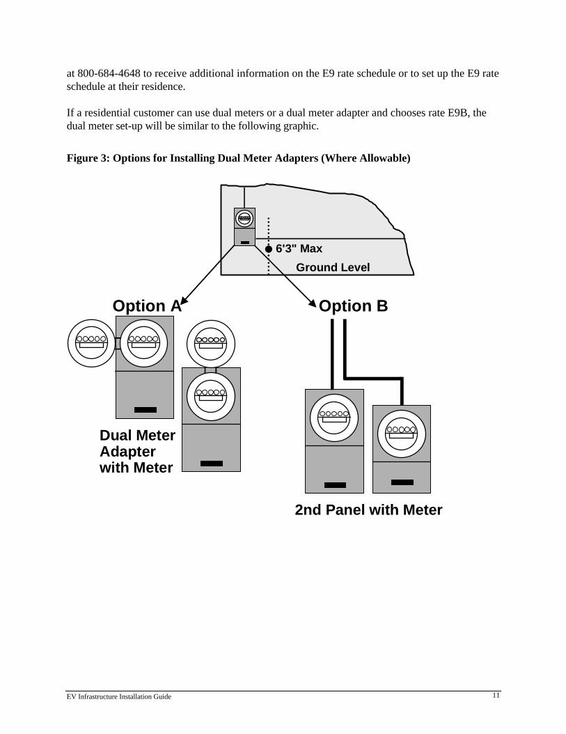
If a residential customer can use dual meters or a dual meter adapter and chooses rate E9B, thedual meter set-up will be similar to the following graphic.
Figure 3: Options for Installing Dual Meter Adapters (Where Allowable)
Ground Level
6'3" Max•
Option A Option B
Dual MeterAdapterwith Meter
2nd Panel with Meter

EV Infrastructure Installation Guide 12
3. CODE REQUIREMENTS FOR INSTALLING EVSE
As with any electrical installation, EV charging infrastructure is governed by various federal,state, and local building codes and requirements. In PG&E’s service territory, the National Elec-trical Code (NEC), the California Electrical Code (CEC), and the California Building Code (CBC)are standards for local jurisdictions to follow to ensure the safe operation of equipment. As men-tioned earlier, these codes are minimum standards, and some municipalities impose additionalsafeguards.
EVSE installations require building permits. Permit costs vary by municipality, and a service panelupgrade will add to the cost.
Currently, only Level 1 and Level 2 charging are allowed for personal use. The NEC and the CECboth require that all components (materials, devices, fittings, etc.) be listed or labeled. However,because some of the EVSE on the market today are still undergoing UL evaluation prior to ULlisting and approval, installers are advised to contact local building officials if questions arise con-cerning equipment usage.
A. EVSE Used in Level 1 Installations:The following code and regulatory issues are associated with the use of Level 1 EVSE:
x Cords and Plugs: The EVSE can be fastened in place or be cord-and-plug connected, but itshould have no exposed live parts (CEC §625.13) and must be grounded (CEC §625.24).
x EV Connectors: (For Conductive Connection Only) Connectors shall be polarized, protectedby double insulation, and non-interchangeable with receptacles in other electrical systems;made to avoid inadvertent contact between the user and live parts; designed to prevent unin-tentional disconnection; and have a grounding pole which connects first and disconnects last(CEC §625.9). The charger or vehicle manufacturer normally supplies this cable and connec-tor to match the connector on the vehicle.
x Markings: All EVSE must be marked “For Use With Electric Vehicles” (CEC §625.15).
x Overcurrent Protection: EVSE feeders and branch circuits must be sized for continuous dutyand have a rating no less than 125% of the maximum load of the EVSE. Where noncontinu-ous loads are supplied from the same feeder or branch circuit, such as the ventilation system,the overcurrent device must have a rating no less than the sum of the noncontinuous loadsplus 125% of the continuous loads (CEC §625.21). For Level 1 charging, either a 15 or 20amp single-pole circuit breaker at the beginning of the circuit, located in the meter-panelbreaker section, will meet this requirement. Note that with a 15 to 20 amp circuit breaker,charging at 12 amps will overload the circuit if an additional 4 to 9 amp load is also on the branch.
EV Infrastructure Installation Guide 13
x Receptacle and Wall Plug: A standard 15 or 20 amp residential wall plug and receptacle areacceptable for Level 1 charging. The receptacle should be wired with the correct polarity anda safety ground. (Depending on local code requirements and type of EV charging equipmentinstalled, most charging equipment will be directly wired, eliminating the need for an in-wallreceptacle.)
x Personnel Protection: The 1999 NEC has been modified to address this issue. According tothe NEC, the EVSE shall have a listed system of protection against electric shock of peopleusing the equipment. The personnel protection system shall be made up of listed protectiondevices and construction features. Regarding cord-and plug-connected EVSE, the interruptingdevice of a listed personnel protection system shall be provided and be an integral part of theattachment plug or be located in the power supply cable not more than 12 inches from the at-tachment plug. The change from the 1996 NEC is that personnel protection systems replaceground fault current interruption (GFCI) devices for protection from shock (NEC §625.22).The 1998 CEC still mirrors the language of the 1996 NEC (CEC §625.22).
x Electricity Back-Feed to Residence Prohibited: The EV must not be used as a standby powersupply for the house, and a means must be provided to prevent power backfeed to the resi-dence (CEC §625.25).
B. EVSE Used in Level 2 InstallationsThe code and regulatory requirements that affect Level 2 EVSE (apart from those listed in thesection on Level 1 EVSE) include:
x Overcurrent Protection: To meet the loads associated with Level 2 charging, a minimum 40amp, two-pole circuit breaker at the beginning of the circuit located in the meter-panel breakersection will be necessary if no additional loads are on the circuit.
x Safety Switch: For EVSE rated at more than 60 amps or more than 150 volts to ground, ameans of disconnect must be installed in a readily accessible location and within sight of theelectric charging connector. If the disconnect is not in sight of the equipment, it must be capa-ble of being locked in the open position (CEC §625.23). Depending on local code require-ments, a fused switch may be needed if the switch is not readily accessible, or is not visiblefrom the main panel.
x Receptacle and Wall Plug: Where the EVSE calls for an in-wall receptacle, a 50 amp, 240volt, 3- or 4-wire wall plug configuration is required. However, most charging equipment willbe directly wired, eliminating the need for an in-wall receptacle. Level 2 EV connectors aredesigned so that they cannot be used with receptacles for other electric equipment, and theEVSE is labeled “For Use With Electric Vehicles” (CEC §625.15, 625.16).
EV Infrastructure Installation Guide 14
x Cables and Connectors: EV charging cables must not exceed 25 feet in length, and they can-not have mid-cord couplings. Cables must be type EV, EVJ, EVE, EVJE, EVT, or EVJTflexible cable. EV charging cables and connectors come with the charger (CEC §625.17). Theconnector must include an interlock to de-energize it when it is unplugged from the vehicle, orwhen it is subjected to stress that may rupture or break it, or when it becomes a shock hazard(CEC §625.18). The grounding pole for conductive connectors are the first contact made andlast broken (CEC §625.9). For inductive charging, the EV and EVSE are electrically isolated,which prevents shock hazard.
x No Back-Feed of Electricity to Residence: The EV cannot serve as a standby power supplyfor the house, and a means must be provided to prevent power from being fed back to theresidence (CEC §625.25).
C. Installations Where Ventilation is RequiredThe need for ventilation in indoor charging facilities is very rare. Few current EV batteries areflooded lead-acid or nickel-iron batteries, the two technologies that release hydrogen. The currentindustry battery standards are sealed lead-acid or nickel-metal hydride (NiMH). In the sealed lead-acid batteries, hydrogen and oxygen recombine into water, eliminating the ventilation require-ment. In NiMH advanced batteries, the battery electrodes absorb and store the hydrogen for laterelectrochemical reaction. Other new batteries such as lithium-ion and lithium-polymer advancedbatteries depend on the electrochemical activity of lithium ions, a light metal, involving no gases.Very few batteries will require ventilation during charging.
In the few circumstances where non-sealed batteries are used, electrolysis (the separation of waterinto hydrogen and oxygen) can be caused when a flooded lead-acid or a nickel-iron battery is fullycharged and additional current is added to the battery. The gas mixture is potentially explosive incertain concentrations, therefore ventilation is required when such batteries are charged in en-closed spaces. Since hydrogen is lighter than air and therefore rises, ventilation must be providedabove the EV if it is charged in an enclosed garage. The lower flammability limit (LFL) of hydro-gen in air is a 4% mixture by volume; locations are classified as hazardous wherever 25% of thehydrogen LFL (a 1% hydrogen/air mixture) is exceeded.
Even though the newer generation of batteries have overcome the need for ventilation, both theNEC and CEC have provisions for ventilation when the situation warrants. California includes theventilation requirements and table in the California Building Code (CBC §1202.2) and as of 1998,in the California Electrical Code as well (CEC §625.29). The ventilation table provided below istaken from the CEC. When a ventilation system is installed, receptacles and power outlets shouldbe marked “For Use with All Electric Vehicles.” When ventilation is not provided, the EVSE, re-ceptacles, and power outlets must be clearly marked “For Use Only with Electric Vehicles NotRequiring Ventilation.” The following table is based on CEC Table 625-29(c). “Minimum Venti-lation Required in Cubic Feet per Minute (cfm) for Each Parking Space Equipped to Charge anElectric Vehicle.”

EV Infrastructure Installation Guide 15
BranchCircuit
Branch-Circuit Voltage
AmpereRating
Single Phase 3 Phase
120 V 208 V
240 Vor
120/240 V
208 Vor
208 Y/120 V 240 V
480 Vor
480 Y/277 V
600 Vor
600 Y/347 V
15 37 64 74 -- -- -- --
20 49 85 99 148 171 342 427
30 74 128 148 222 256 512 641
40 99 171 197 296 342 683 854
50 123 214 246 370 427 854 1066
60 148 256 296 444 512 1025 1281
100 246 427 493 740 854 1708 2135
150 -- -- -- 1110 1281 2562 3203
200 -- -- -- 1480 1708 3416 4270
250 -- -- -- 1850 2135 4270 5338
300 -- -- -- 2221 2562 5125 6406
350 -- -- -- 2591 2989 5979 7473
400 -- -- -- 2961 3416 6832 8541
For other single-phase values, cubic feet per minute can be calculated by multiplying volts timesamperes and dividing by 48.7: cfm = (volts x amps)/48.7.
For three-phase values, cfm can be calculated by multiplying volts by the square root of three(1.73), then by amps, and dividing by 48.7: cfm = (volts x 3 x amps)/48.7.
Required ventilation equipment includes both supply and mechanical exhaust which intakes from,and exhausts directly to, the outdoors. The passive intake vent should be placed low on one sideof the enclosed space, and the exhaust fan in the ceiling on the other side. The ventilation systemmust be interlocked with the EV charger to turn on when the charger starts, and should continueto operate at least five minutes after charging is completed.
D. Codes Governing EVSE SitingThe following regulatory and code issues affect the placement of EVSE:
x The NEC calls for indoor EV charging receptacles/coupler to be stored or located between 18and 48 inches above the floor.
x In outdoor charging locations, chargers must be stored or located at least 24 inches above thegrade. The same is true for mounting outdoor power outlets.
x All explosive materials, flammable vapors, liquids and gases, combustible dust or fibers, andmaterials that ignite spontaneously on contact with air should be kept away from all EVSE.
EV Infrastructure Installation Guide 16
The installer is referred to NEC Articles 500 to 516 (equipment and procedures for installa-tion of electrical systems in hazardous locations) if the location has been designated as a Clas-sified (Hazardous) Location.
E. Installations Located in Flood ZonesIf a charging station is in a flood zone, all chargers must be installed above the base flood eleva-tion or waterproofed to include personnel protection so that it complies with codes for electricalequipment which may become submerged.
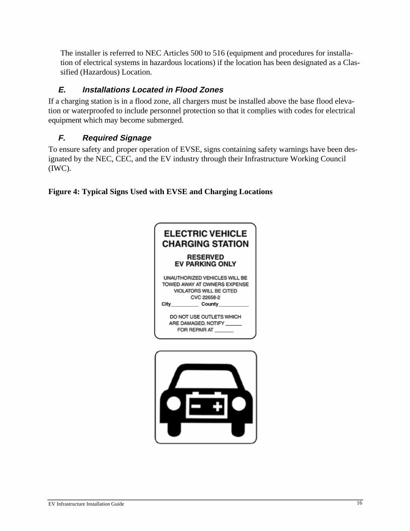
F. Required SignageTo ensure safety and proper operation of EVSE, signs containing safety warnings have been des-ignated by the NEC, CEC, and the EV industry through their Infrastructure Working Council(IWC).
Figure 4: Typical Signs Used with EVSE and Charging Locations
EV Infrastructure Installation Guide 17
G. Lighting RecommendationsThe NEC and CEC do not set requirements for lighting at EV charging facilities. However, de-signers and installers should use common sense to ensure that enough light be available for secu-rity reasons and safe operation of the EVSE. Using best practices for similar settings, a minimumof 300 lux and 30 footcandles of lighting should be provided. Additional lighting may be neces-sary depending on the size and importance of written instructions, special needs of operators, andthe contrast of objects illuminated.
H. Disabled AccessADA Compliance: Connector and receptacle heights, special curb cutouts, and disabled parkingaccess are some of the measures that may be necessary to make a charging station fully accessiblefor the disabled. Each operator must assess their compliance with the federal Americans withDisabilities Act, as well as state and company policies regarding disabled access.
The State of California’s Division of the State Architect has issued “Interim Disabled AccessGuidelines for Electric Vehicle Charging Stations” (Policy #97-03). EV charging stations are re-quired to be accessible because they offer a service to the general public. When EV charging iscoupled with regular parking, the EV charging is considered the primary service. The followingtable should be used in determining the required number of accessible chargers:
Number of Chargers Pro-vided at a Site
Number of Accessible ChargerSpaces Required
1 to 25 126 to 50 251 to 75 376 to 100 4
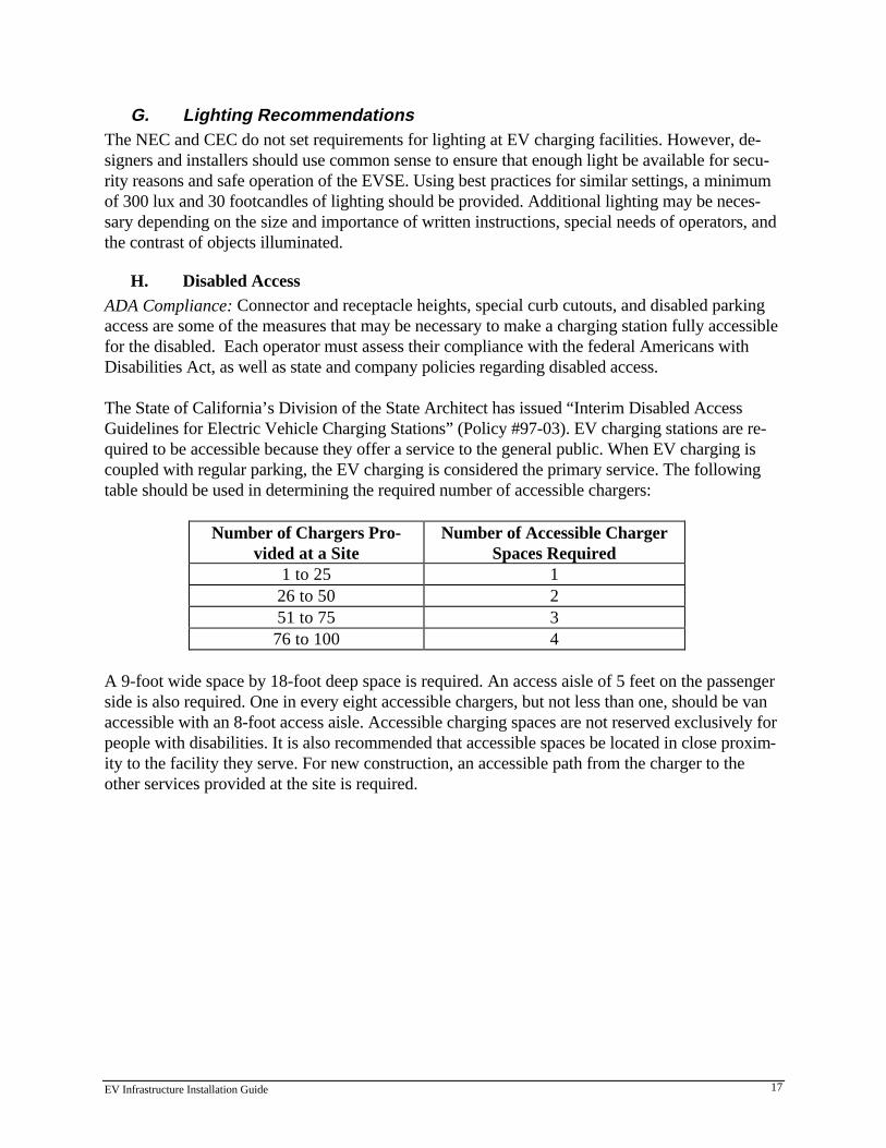
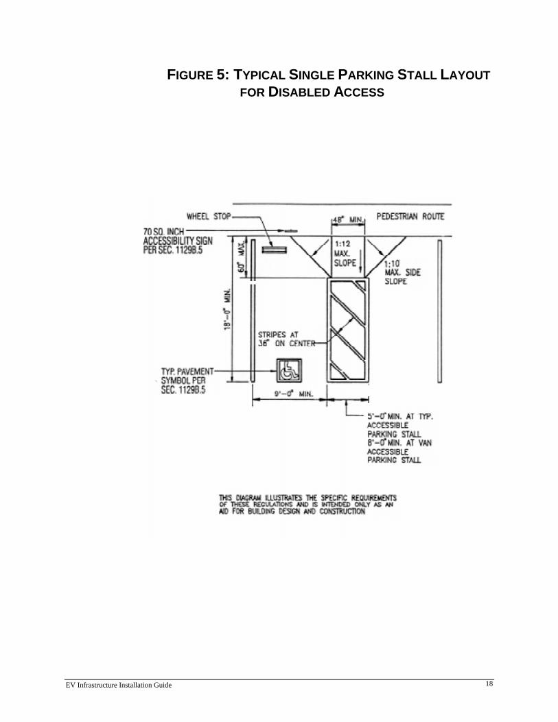
A 9-foot wide space by 18-foot deep space is required. An access aisle of 5 feet on the passengerside is also required. One in every eight accessible chargers, but not less than one, should be vanaccessible with an 8-foot access aisle. Accessible charging spaces are not reserved exclusively forpeople with disabilities. It is also recommended that accessible spaces be located in close proxim-ity to the facility they serve. For new construction, an accessible path from the charger to theother services provided at the site is required.
EV Infrastructure Installation Guide 18
FIGURE 5: TYPICAL SINGLE PARKING STALL LAYOUTFOR DISABLED ACCESS
EV Infrastructure Installation Guide 19
4. EV CHARGING IN SINGLE FAMILY RESIDENCES
Residential EV users are fortunate in that suppliers of EVs and EVSE provide substantial assis-tance in setting up charging infrastructure. PG&E also provides assistance to those who havequestions about the adequacy of their current electrical service. In addition, electrical contractorsshould be familiar with technical and permitting issues. This chapter provides an overview of thenecessary steps in the installation process.
As mentioned in earlier sections, charging facilities must comply with all local, state, and nationalcodes and regulations, regardless of the type of installation, and all work requires a permit andshould be handled by appropriately licensed contractors. Contractors should make sure to checkwith the local planning department before starting work. It is important to note that PG&E willnot energize a new meter without a properly signed building inspection.
This chapter is presented as a step-by-step process that should be followed to ensure properEVSE installation. This chapter also includes information specific to multi-family residences.
A. Step 1: Determine the Charging and Battery TypesBefore any equipment purchases and electrical services changes are made, the homeowner shoulddetermine the type and model of EVSE the EV manufacturer provides or specifies, and thatequipment's electrical requirements. As discussed in Chapter 2, conductive and inductive chargingequipment require different connectors and are installed in a different manner. The EV dealershipwill also know if the vehicle’s battery requires ventilation during charging.
B. Step 2: EV Utility Rates and Meter OptionsBefore installing the EVSE, contact PG&E for more information about its special EV rate sched-ules (see Chapter 2E PG&E EV Rates). It is the homeowner’s responsibility to sign up for rateschedule E9 with PG&E. For the homeowner to take advantage of PG&E’s E9B rate schedule,the residence must be able to separately meter EV charging. As mentioned earlier, some munici-palities do not allow separate meters to be installed in a residence. Homeowners are advised tocheck with their city’s building inspection department.
C. Step 3: Determine the Home’s Electrical CapacityThe installation contractor can tell the homeowner if the home has adequate electrical capacity forEV charging. Many people will want to use Level 2 EVSE due to the quicker charging times, butmany older homes may not have sufficient electrical capacity. In those instances, they must add anew electrical service panel to handle the 240 volt, 40 amp Level 2 charging circuit needed forLevel 2 charging. A quick survey by an electrical contractor can determine if a service panel up-grade—generally the most costly step in installing charging facilities—is necessary.
D. Step 4: Determine EVSE PlacementThe following factors should be considered when determining where to place EVSE:
EV Infrastructure Installation Guide 20
1. Safety Issues in Enclosed GaragesEnclosed garages offer convenience, safety and security. Most single family residences will em-ploy this option. Some of the factors to consider when planning an EVSE installation in an en-closed garage include:
�� The EV charger should be placed where the cable will stretch the shortest distance, where theuser can easily reach the charger handle, and where it does not block entry or exit. Therefore,check the location of the charging port on the EV before planning the EVSE location.
�� Avoid having the cords and cables cross areas with heavy foot traffic.
�� If practical, use cable management to prevent accidents.
�� As mentioned in Chapter 3, EVSE must not be installed near explosive material; flammablevapors, liquids and gases; combustible dust or fibers; and materials that ignite spontaneouslyon contact with air. See NEC Articles 500 to 516 for more information.
2. Extending Electrical ServiceIf a detached garage does not have electrical service, the installer should help the homeowner de-cide where to place the wiring for the EVSE: overhead, which is less expensive but visually lessattractive option; or underground which can be more expensive but is also more attractive.
3. Outdoor ChargingCharging equipment is weatherproof and can be placed outdoors, but it should be protected fromdamage. It is also recommended that EVSE be installed in a secure location to protect againstvandalism. In addition, EV buyers should check the EV manufacturer’s recommended operatingand charging temperature range for the battery pack and site the EVSE accordingly. This appliesto both indoor and outdoor locations.
E. Step 5: Drawing Up the Installation PlansAfter determining the electrical equipment needs and the optimal location of the EVSE, the nextstep involves drawing up precise plans for the branch circuit and EVSE installation. Part of thisstep involves checking that the planned installation complies with the code requirements assummarized in Chapter 3. Most importantly, local building code officials should be contactedregarding special requirements and documentation needed to obtain the permit and pass thebuilding inspection. Then, the EV buyer should select a currently licensed electrical contractor.
The contractor will help draw up any installation plans to be submitted as part of the permit ap-plications. For a residential permit, most jurisdictions require a drawing that shows:
�� The electrical panel schedule
�� The wiring of the new branch-circuit, including the meter, charger, and all receptacles
�� If ventilation is required, the location of the vent fan, its specifications, and air inlet and airflow in cubic feet per minute
�� The location of the EVSE in the garage and any potential hazards
EV Infrastructure Installation Guide 21
The installation plan should be detailed enough for the local code official to determine that theinstallation meets code requirements, is safe, and meets all federal, state, and local requirements.Drawings should be complete but not overly detailed.
Above all, the EV owner and contractor should follow the instructions provided by the EV andEVSE manufacturers to ensure safe and proper equipment operation.
F. Step 6: Obtaining Permits, Performing the Installation, and Conducting aSite Inspection
When the installation plan is drawn up, the EV owner then applies for the permit, which varies inprice by task and jurisdiction. The contractor can begin installation when the permit is issued.When the installation is complete, the owner should arrange for an inspection with the localbuilding inspector, and then make any required changes. Figure 4 on the following page illustratesa typical residential EV infrastructure site plan using a separate meter for the EVSE.
G. Other Issues Pertaining to Single Family ResidencesIn addition to following the process outlined above, the homeowner should be aware of other is-sues that can affect their EVSE installation:
1. InsuranceAccording to insurance companies contacted, EVSE in a single-family residence does not requirea rider to the existing insurance policy or separate coverage. EV owners should check insurancerequirements with their insurance agent.
2. CostsIn general, the cost of an EVSE installation ranges from $500 to $1,500 if an electrical panel up-grade is not required. If a panel upgrade is needed, the installation cost will be approximately$2,500. These costs do not include the EVSE itself. Some EV manufacturers include EVSEequipment in their vehicle lease price. As mentioned earlier, check with the EV dealer first beforestarting with the installation planning.
The following factors will influence the total installation cost:
x The particular EVSE selected
x Whether the garage is attached or detached
x Electrical service panel upgrade requirements
x The use of trenching vs. use of existing conduit or raceway
x The electrical panel location relative to the EVSE
x Type of construction (slab or crawlspace)
x Ease of installing new wiring

EV Infrastructure Installation Guide 22
Figure 5: Sample Residential EV Infrastructure Plan
AElectrical Panel Schedule
Charger Hard Wired40" above Floor
AHouse Meter
EV Meter
B
Utility Drop
OutsideAir Intake
ChargerConnector
Circuit Breakerin Meter Panel
Conduit plus 240V32A EV Branch CircuitRated to 40A
• Level 2 Conductive or Inductive Charger 240V, 32A, All Components andCables New
• Connector Interlock Includes Automatic De-energizer for Vehicle, Cable andConnector
• Circuit Breaker in Meter Panel
• Charger Installed 40 Inches Above Floor
BElectrical Vehicle Supply Equipment
240V 30AGarage Dryer
240V 40AEV Meter
1 2120V 15AHouseLighting
120V 15ABedroomReceptacles
3 4
120V 15ADining RoomLiving RoomReceptacles
5120V 15AKitchenReceptacles
6Available
7Available
8
HOUSEATTACHED GARAGE
EV Infrastructure Installation Guide 23
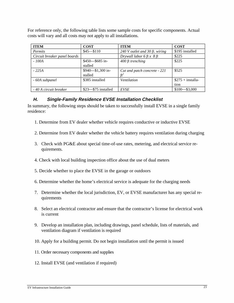
For reference only, the following table lists some sample costs for specific components. Actualcosts will vary and all costs may not apply to all installations.
ITEM COST ITEM COSTPermits $45—$110 240 V outlet and 30 ft. wiring $195 installedCircuit breaker panel boards Drywall labor 6 ft x 8 ft $225- 100A $450—$685 in-
stalled400 ft trenching $225
- 225A $940—$1,300 in-stalled
Cut and patch concrete - 221ft2
$525
- 60A subpanel $385 installed Ventilation $275 + installa-tion
- 40 A circuit breaker $23—$75 installed EVSE $100—$3,000
H. Single-Family Residence EVSE Installation ChecklistIn summary, the following steps should be taken to successfully install EVSE in a single familyresidence:
1. Determine from EV dealer whether vehicle requires conductive or inductive EVSE
2. Determine from EV dealer whether the vehicle battery requires ventilation during charging
3. Check with PG&E about special time-of-use rates, metering, and electrical service re-quirements.
4. Check with local building inspection office about the use of dual meters
5. Decide whether to place the EVSE in the garage or outdoors
6. Determine whether the home’s electrical service is adequate for the charging needs
7. Determine whether the local jurisdiction, EV, or EVSE manufacturer has any special re-quirements
8. Select an electrical contractor and ensure that the contractor’s license for electrical workis current
9. Develop an installation plan, including drawings, panel schedule, lists of materials, andventilation diagram if ventilation is required
10. Apply for a building permit. Do not begin installation until the permit is issued
11. Order necessary components and supplies
12. Install EVSE (and ventilation if required)

EV Infrastructure Installation Guide 24
13. Notify building department that the installation is ready for inspection
14. Comply with inspector's change orders, if any are issued. The city will notify PG&E thatthe circuit is ready to be energized after it passes inspection
15. Charge and drive the EV.
The following flowchart illustrates the process.
2. Hire Contractor
3. Installation Plan
4. Obtain BuildingPermits
5. Install EVSE
6. Permit Inspection
7. Charge Vehicle
1. Phone Calls
EV/EVSE Supplier• Inductive or conductive?• Charging level?• Ventilation required?• Special requirements?
PG&E• Special requirements?• Impact on rates?• Apply for TOU rates
Building Permit Office• Local requirements?• Obtain application form• Cost?
• Current serviceadequate?
• Order TOU meter ifallowed
• Special meteringrequired?
• Upgrade electrical panel?• Ventilation required?• Charging level?• Local requirements?• Outdoor or garage?
If necessary, PG&Eupgrades feeder lines
City notifies utility thatEVSE passed inspection
PG&E installs TOU meter
Comply with change orders

EV Infrastructure Installation Guide 25
I. Issues Related to Installations in Multifamily ResidencesMany of the steps taken to complete an EVSE installation at a single-family residence will applyto multifamily residences. However, the following issues are specific to this customer segment andmust be addressed before installation begins:
x The ownership of the electrical work and circuit from the meter to the charger, which a tenantcannot take when moving
x How the EVSE will be connected to existing circuits if a separate meter is not possible, along witharrangements for paying electricity bills
x The ownership of the EVSEx Determining responsibility for any increased insurance costs related to the EVSEx The location of the chargerx Determining payment arrangements for any mechanical, civil and electrical engineering work
and landscaping required for the site
1. Ownership of EVSEOwnership of EVSE becomes a potentially contentious issue in apartment buildings and condo-miniums. The EV buyer must settle the issue before any additional planning starts. How this isresolved will affect who pays for the installation, who is responsible for permits, metering issues,electricity payments, and whether or not the EV owner can keep the EVSE upon vacating thebuilding. The following sections examine how these issues might be discussed and resolved fortwo different types of residences.
2. ApartmentsIn virtually all situations, the landlord must approve any EVSE installation. Tenants should dis-cuss installation cost with the property owner or manager to see if the property owner will installthe EVSE and make an appropriate rent adjustment to cover its cost. One possible arrangement ishaving the apartment owners pay for installation of the circuit, while EV owners could pay for thecharging equipment and take it with them when they move. Also, some municipalities allow onlyone meter per unit plus one for common areas. This can negate the use of a dual meter setup.
3. Condominiums and TownhousesSome of the issues are similar in condominiums. The EV owner in a condo or townhouse willprobably need the homeowners’ association approval to install the EVSE. The homeowner shoulddiscuss installation cost with the homeowners’ association to see if the association, which may beeligible for a tax deduction, will install the EVSE and make an appropriate adjustment to associa-tion dues or fees to cover its cost.
4. Metering ArrangementsDepending on the municipality, the property owner/manager, or homeowners’ association, mustdetermine whether to:
x Run the service from the relevant residential unit
x Meter each EV parking space separately
EV Infrastructure Installation Guide 26
x Run all chargers off one meter
5. Electrical CapacitySince many multifamily dwellings are built up to the full capacity of their electrical service, build-ing owners/operators must determine whether they have adequate electrical service for the num-ber of planned EV charge stations. The owner/operator should also take any future EV chargingneeds into consideration. They may necessitate the upgrading of the feeder lines and transformersserving the site, which can delay the service. If upgrades to the transformers or the electrical panelon site are required, the party paying for the installation may incur significant expenses.
6. InsuranceOwners of multifamily residences, condos, and townhouses may need additional insurance tocover the cost of the EVSE and liability. Property damage insurance should cover EVSE and in-stallation costs. Determining who pays for the coverage and the extent of coverage are issues fornegotiation between the apartment owner and tenant, or between a condo/townhouse owner andthe homeowners' association. A local insurance agent should be contacted for specific details.
7. CostsAs with any EVSE installation, the cost will depend on the type of EVSE, number of spaces re-quired, and siting requirements. the following table lists. For reference only, the table in the nextchapter lists some sample costs for specific components in typical EVSE installations at multifam-ily residences. Actual costs will vary and all costs may not apply to all installations.
EV Infrastructure Installation Guide 27
5. EV CHARGING AT FLEET FACILITIES
Government, utility, and private fleets are currently the largest market for EVs. Federal and Cali-fornia clean air regulations specifically target fleets in their attempts to increase the number ofclean air vehicles. PG&E has been a leader in introducing both EVs and natural gas vehicles intotheir fleet and can provide considerable assistance to other organizations attempting to meet cleanair mandates.
The process of establishing EV charging infrastructure in fleet facilities is more complicated thanin residential settings but many of the underlying issues are the same. This chapter outlines issuesthat are specific to fleet applications.
A. Site PlanningMany siting issues influence the successful planning of a charging facility:
1. Number of EVs and ChargersPlanners must be realistic when determining the number of EVs a fleet will include, because thatnumber will determine each facility’s charging requirements. Estimates must include the numberof fleet vehicles to be added over the next three to five years, with special attention to meetingupcoming state and federal AFV mandates. The facility operator should also consider plannedflexibility that allows the site to grow with developing technologies or changes in charging re-quirements. Planners should seriously consider installing extra circuits and additional electricalcapacity during initial construction, when costs are minimal.
Fleet managers should analyze what the fleet’s charging schedule will be by developing a chargingcurve for each vehicle in the fleet (see next page). The curve matches the time of day a vehicle isrecharged with the amount of energy used. After developing a curve for each vehicle, they can beaggregated to get a facility-wide fueling curve. This calculation will determine the frequency ofcharging and the energy required to service the entire facility. It will also facilitate equipmentscheduling by helping determine the amount of time needed to recharge each vehicle. Based onthe information taken from the charging curve, a facility manager can plan: charging needs(number of chargers), facility energy needs, and the necessary mix of Level 2 and Level 3 charg-ing. The vehicle manufacturer and EVSE supplier can provide fleet managers with sample charg-ing time and electricity consumption figures in order to develop a charging curve.
Several factors must be considered when deciding between Level 2 or Level 3 charging. Becauseof the length of time necessary to complete Level 2 charging, a facility will most likely need onecharger per vehicle, as charging will take place overnight. This scenario may require additionalland, island construction, cabling, and transformers—and will require the installation of appropri-ate EVSE. These factors can increase capital costs significantly. Installing Level 3 charging willraise costs for cabling, transformers, and chargers, but possibly lower land and construction costs.
EV Infrastructure Installation Guide 28
How a fleet uses its vehicles will determine the appropriate charging method. Vehicles requiringexpanded range may require a fast mid-day charge, requiring rapid Level 3 charging. However,Level 3 charging will raise equipment and electricity costs. In addition, some EV manufacturerswill void the vehicle’s warranty if the owner uses Level 3 charging. Each facility manager mustcarefully assess their fleet use and weigh the cost differences before deciding on using one charg-ing level or a combination of both.
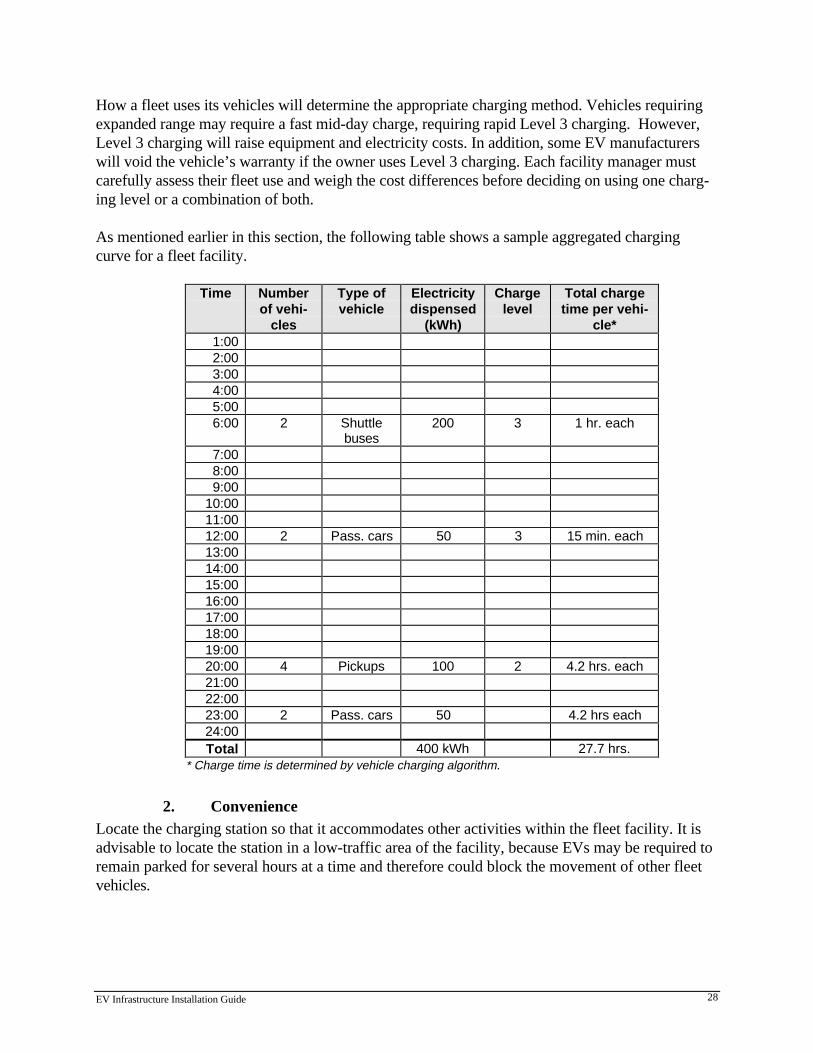
As mentioned earlier in this section, the following table shows a sample aggregated chargingcurve for a fleet facility.
Time Numberof vehi-
cles
Type ofvehicle
Electricitydispensed
(kWh)
Chargelevel
Total chargetime per vehi-
cle*1:002:003:004:005:006:00 2 Shuttle
buses200 3 1 hr. each
7:008:009:00
10:0011:0012:00 2 Pass. cars 50 3 15 min. each13:0014:0015:0016:0017:0018:0019:0020:00 4 Pickups 100 2 4.2 hrs. each21:0022:0023:00 2 Pass. cars 50 4.2 hrs each24:00Total 400 kWh 27.7 hrs.
* Charge time is determined by vehicle charging algorithm.
2. ConvenienceLocate the charging station so that it accommodates other activities within the fleet facility. It isadvisable to locate the station in a low-traffic area of the facility, because EVs may be required toremain parked for several hours at a time and therefore could block the movement of other fleetvehicles.

EV Infrastructure Installation Guide 29
3. Cable ManagementCords and cables associated with charging equipment should not cross sidewalks or pedestriantraffic patterns.
4. Ventilation NeedsAs discussed in Chapter 2, most of today’s advanced batteries do not require ventilation duringcharging. However, some earlier battery types do produce and emit gases during charging as aresult of electrolysis. Due to the concerns related to these older battery types, the facility man-ager should ensure that adequate ventilation is in place when older battery types that do emitgases are included in their fleet.
The cost of ventilation equipment, including fans, ducts, and air handlers, ranges from $400 for a320 cfm centrifugal roof exhauster to $2,550 for a 1000 cfm industrial exhauster. Equipmentshould be based on the specific enclosure and the number of chargers installed.
5. Battery Operating and Charging Temperature LimitsSome EV batteries have operating and charging temperature limits, so under some circumstances(such as cold climate conditions) it may be necessary to site the EVSE in an enclosed area.
6. Standing Water and IrrigationEven though all EVSE have been designed for safe operation in wet areas, user comfort will beincreased by not placing equipment in locations where water pools or within the spraying area ofirrigation systems.
7. Curbs, Wheel Stops, and SetbacksTo avoid vehicles from inadvertently driving into the EVSE, provide curbs, wheel stops, and set-backs. Consider user access and mobility issues when installing this equipment (see section 10 inthis chapter – Disabled Access).
8. VandalismPlanners should site EVSE to avoid the risks of vandalism or tampering. Consider including mo-tion detectors, security lighting, tamper alarms, locked enclosures, and fences. The level of pro-tection required will depend on the location of the EVSE, whether access is public or private, andthe overall security requirements of the facility.
9. SignsFleet operators may want signage to designate EV-only parking spaces. These should be posi-tioned high enough to be seen over parked vehicles.
10. Disabled AccessADA Compliance: Connector and receptacle heights, special curb cutouts, and disabled parkingaccess are some of the measures that may be necessary to make a charging station fully accessiblefor the disabled. Each operator must assess their compliance with the federal Americans withDisabilities Act, as well as state and company policies regarding disabled access.

EV Infrastructure Installation Guide 30
The State of California’s Division of the State Architect has issued “Interim Disabled AccessGuidelines for Electric Vehicle Charging Stations” (Policy #97-03). EV charging stations are re-quired to be accessible because they offer a service to the general public. When EV charging iscoupled with regular parking, the EV charging is considered the primary service. The followingtable should be used in determining the required number of accessible chargers:
Number of Chargers Pro-vided at a Site
Number of Accessible ChargerSpaces Required
1 to 25 126 to 50 251 to 75 376 to 100 4
A 9-foot wide space by 18-foot deep space is required. An access aisle of 5 feet on the passengerside is also required. One in every eight accessible chargers, but not less than one, should be vanaccessible with an 8-foot access aisle. Accessible charging spaces are not reserved exclusivelyfor people with disabilities. It is also recommended that accessible spaces be located in closeproximity to the facility they serve. For new construction, an accessible path from the charger tothe other services provided at the site is required.
B. Checklist for Fleet Facility EVSE SitingFacility planners should answer the following facility planning questions before proceeding fur-ther:
�� What level of charging will be used?
�� What are the charger requirements?
�� Is the existing electricity supply adequate for fleet needs?
�� What is the location of the electrical service relative to the charging equipment siting?
�� What will be the impact of electricity rates on choosing alternative approaches to fleet EVcharging?
�� What are the cost trade-offs between charging levels and equipment locations?
�� Have I addressed all of the relevant federal, state, and local code requirements?
C. Engineering and ConstructionMany pieces of equipment are unique to EV charging facilities, and fleet managers should becareful to select contractors familiar with their specifications. In addition to the standard civilengineering work required to construct any fueling facility, EV facilities will require considerablymore electrical service and electrical equipment installation.
A primary consideration for the site designer and the facility manager is the condition and loca-tion of the existing electric utility equipment. These factors will govern the number and size of
EV Infrastructure Installation Guide 31
formers, necessary trenching or overhead cabling, conduits, amount of cabling, and associatedinstallation costs.
The key component in the interface between the existing electrical system and the EVSE is thetransformer. To provide adequate power for Level 2 charging equipment, existing electrical serv-ice must be stepped down to a level that can work with Level 2 charging equipment: 208–240volts. If not already available at the site, it will be necessary to install an isolation transformer ca-pable of stepping electricity to 208–240 volts for Level 2 charging, or up to 480 volts for Level 3charging. Isolation transformers can cost between $7,200 to $8,500.
D. Charging EquipmentAs discussed in Chapter 2, charging equipment decisions depend on the EV charging designation:inductive or conductive, Level 2 or Level 3. Until the market determines which charging technol-ogy dominates, it is likely that both inductive and conductive charging will develop in parallel.Until a charger and connector standard evolves, some fleets may select a mix of inductive andconductive chargers, depending on what their fleet EVs require.
Presently, there are several different manufacturers supplying different types of connectors forconductive charging equipment. Facility managers should ascertain that the connector is com-patible with the receptacle on the vehicle. Vehicle manufacturers can supply the proper connectorspecifications for their vehicles.
E. Fleet Recharge Management SystemsAnother component of a charging facility will be its Fleet Recharge Management System (FRMS).An FRMS is an integrated, computerized charging system that is designed to eliminate the costlyprocess of managing electric vehicle charging for fleet applications by automatically sequencingmultiple chargers. These systems are designed to accomplish the following goals:
x Automate recharging of fleet vehicles, thereby reducing the need for human intervention in theprocess
x Eliminate redundant charging infrastructure at charging locations where more than one vehiclewill be charged
x Reduce overall fleet management labor costs
x Reduce electric charging costs through load management
x Reduce electric utility infrastructure needs, thereby lowering the cost to serve the load
x Allow fleet operators to choose all charging parameters The key to an FRMS is its ability to manage charger sequencing. This functionality will determinethe ultimate value of any system that is developed. It is likely that any successful system will becomputer-controlled and be able to communicate with the local utility to take advantage of time-of-use rates or real-time pricing. By managing the electrical load in this manner, the FRMS willuse electricity economically and will optimize fleet energy use.

EV Infrastructure Installation Guide 32
One FRMS is currently under development by Southern California Edison and has been demon-strated using existing hardware. The goal of this pilot is to study the feasibility of the system, de-termine its strengths and weaknesses, determine fleet operator needs, and transform those needsinto algorithms that can be improved in the future. This knowledge will be used to develop hard-ware that can be easily mass-produced to lower overall system costs. The key component of this FRMS is the charge controller that automates the charging process.Through a PC-compatible computer, the controller distributes enough charge to maintain lowoverall peak electricity costs, while keeping connected vehicles in a state of full charge. It acts byinterfacing with individual charging meters to perform the following tasks:
x Report on the required charge of each vehicle
x Determine the initial charge level of each plugged-in vehicle
x Determine the energy flow through the system
x Receive synchronization commands from the local utility through a communications device
x Display historical and real-time information
x Provide diagnostics
Other utilities are investigating different load management devices. The Electric Vehicle ResearchNetwork has sponsored a study of charge management systems in conjunction with Norvik. Thissystem is a charge sequencer for fast chargers and does not have some of the enhanced featuresmentioned above.
The full costs of FRMS have yet to be determined but could be minimized by the use of existingcomputers, meters, communication devices, and kiosks. It is estimated that costs for a completeFRMS will range from $4,000 to $10,000 depending on the number and level of chargers. Formore information on the SCE system, please contact Sam Katagi at (626-302-9515).
F. Metering and Billing SystemsWhile metering/billing systems are most often associated with public refueling systems, fleets mayalso want to investigate their use. Along with the FRMS, these systems can be very helpful inmatching electricity consumption to individual vehicles. A typical system could incorporate ad-vanced billing capabilities to help generate detailed monthly statements, including tracking by ve-hicle identification number. This system would allow fleet managers to track EV use, chargingtimes, and associated energy costs. Several system options are available to fleet operators and aredesigned to accommodate individual access and reporting policies, including direct utility billingor point-of-sale billing. Metering and billing system prices vary, depending on which features areincluded. Prices range from $800 for a debit card system to $2,700 for a cashless voucher systemto $14,000 for a TECH-21 proprietary card system. Fleet managers should assess their needs inthis area to choose the appropriate system. Because the current billing systems are most compati-ble with gasoline and diesel fuels, charging equipment manufacturers would have to modify theirsystems for EV use. Recently, EVSE manufacturers have begun to make their equipment com-patible with existing metering and billing systems.
EV Infrastructure Installation Guide 33
G. Electrical ServiceGenerally, one charger will be required for each EV for overnight recharge (Level 2). The typicalelectrical demand for original equipment manufacturer vehicles using 240V single-phase service is7 kW while charging for buses and fast chargers (using 480V three-phase service) can have de-mand levels of 50 kW or more. Actual kW demand is determined by the individual charging algo-rithm required by the vehicle. PG&E can help the fleet manager determine electricityrequirements and compare them to existing service. If the feeder line must be upgraded and newtransformers added, the organization should add sufficient capacity to meet the site's EV chargingneeds for several years. If the fleet manager plans to install Level 3 fast chargers, the electricalservice requirements should also meet this load. When evaluating electrical service, managersshould examine the following issues:
x Service Level. Determine the location, capacity and types of service panels and on-sitetransformers.
x Distances Between Equipment. Determine the distance between service entrance, trans-formers, panels, subpanels, and parking locations.
x Identification of Potential Hazards. Ensure that EV charging spaces are not located nearpotentially hazardous sites such as gasoline fueling areas.
When determining electrical needs for recharging, the fleet manager should contact PG&E to de-termine if existing feeder lines and equipment can provide the service, or if they must be up-graded.
Other factors to be considered include the costs of running three-phase power to the site andstepping it down to single phase, or using high-voltage single phase and a step-down transformerto the appropriate voltage. Again, local utilities will be able to assist facility planners in deter-mining what service changes or upgrades will be necessary.
H. Electric RatesThe additional electrical demand for each EV charging during peak-demand periods may move acustomer into a higher rate category. Charging multiple EVs may also trigger a surcharge for thereactive component of energy consumed. Fleet managers should discuss the impact of EV charg-ing on rates with a PG&E representative. During the planning process, it is also important to dis-cuss potential loads so that PG&E can assess their impact on PG&E’s overall system. Fleetcharging may have some effect on peak power demand, especially when Level 3 charging is used.The integration of an FRMS at the fleet site can manage and minimize demand by schedulingcharging at off-peak times whenever possible.
I. Site Installation PlanMany municipalities require EV fleets to develop and submit an installation plan for engineeringreview and approval. Fleet managers may want to hire an electrical contractor for this task. A siteplan typically describes:
EV Infrastructure Installation Guide 34
x Location of the main electrical panel, branch circuits, and conduits
x Location of hazardous materials
x Location of charging stations
x Lighting
x Traffic flow
x Ventilation (if necessary)
x Description and locations of signs
x Curbing, wheel stops, cutouts, setbacks, and bumper guards
x Parking spaces, striping, driveways, and walkways
x Landscaping
J. Building PermitsBuilding and electrical permits are required for EVSE installations (see Chapter 3). Some utilitieswill not energize new charging circuits until they have passed inspection and the city or countynotifies the utility. The cost of the permit and installation varies by municipality and depends onthe scale of the upgrade.
K. CostsThe cost of installing fleet charging facilities can vary dramatically depending on the followingfactors:
x The number of circuits and chargers installed
x Whether the facility is indoors or outdoors
x The need to upgrade electrical service to the charging facility
x Whether ventilation is or is not required
x Whether Level 3 fast charge equipment is used or not
x Availability of discounts, tax deductions, and rebates from air districts and others.
In general, the cost to its fleet customers of installing EVSE range from $500 per vehicle per siteto more than $5,000 per vehicle per site. The average cost per vehicle is $2,000.
For reference only, the following table lists some sample costs for specific components. Actualcosts will vary and all costs may not apply to all installations. The costs quoted are applicable forfleet, public access, and multifamily charging installations.

EV Infrastructure Installation Guide 35
Sample EV Charging Installation Costs for Public, Fleet, or Multifamily Buildings (all esti-mates are for installed costs)
Item CostPower Distribution Sub-Panel-200A, 120/240 VAC single phase; three wires with main circuit breaker; six 40A/2Pbranch circuit breakers
$1,435 *
Transformer50 kVA, 480/277 VAC primary, 120/240 VAC; 3 wires secondary; dry type NEMA 1enclosure
If power comes directly from utility distribution system: transformer pad; NEMA 3R,200A, 120/240 VAC; 3 wires combination meter/main service and panelboard; groundrod (PG&E can furnish and install thetransformer.)
$ 3,975 *
$ 5,300
Cables/Conduitsa) 40A branch circuit - Above ground installation - Underground installation
b) 200A feeder circuit - Above ground installation - Underground installation
$3.85/linear ft **$6.85/linear ft **
$13.25/linear ft **$21.00/linear ft **
Lighting250 watt, metal halide, parking lot lightinga) Wall or ceiling mountingb) On 16 ft galvanized steel pole, concrete base
$640 each *$2,750 each *
Concrete IslandIn-place concrete island 6 in thick reinforced $7.20/ft2 **
Concrete Steel Pipe (Transformer or EVSE protection)Concrete fill steel pipe, 8 ft high, set 4 ft in ground, rounded top, painted $155 each *
Concrete Bumper (EVSE protection)4 ft long precast concrete bumper $88 each *
Pavinga) Demolitionb) Asphalt paving composite
$1.95/ft2 **$33.00/ft2 **
Signs24 in x 24 in reflective signs; 2 in galvanized steel pole $200 each *
LandscapingSoil preparation, irrigation system, sod (excludes trees and shrubs) $6.10/ft2 **
* Sample costs only. Actual cost may differ significantly depending on location, site requirements,installation, and equipment specification.
** Sample costs provided by Ocampo Esta Corporation. Actual cost may differ significantly.

EV Infrastructure Installation Guide 36
L. Checklist for Vehicle Fleet Charging1. Estimate 3–5 year EV purchase plans.
. Determine recharging locations.
3. Estimate the electrical load at those locations.
x Determine whether to use Level 2 or 3 charging and type of charging to be used: in-ductive and/or conductive
x Obtain charger requirements from vehicle and charger suppliers
x Develop charging curves
x Determine the appropriate number of chargers
4. Contact vehicle and charger suppliers.
x Confirm charging needs and types
x Identify any special ventilation requirements
x Identify any other special considerations for the specific equipment 5. Contact PG&E.
x Assess existing electricity supply
x Determine necessary electrical service upgrades
x Review metering requirements
x Determine the impacts of rates on choosing alternative charging methods
x Determine if any other special requirements exist 6. Develop a detailed facility site plan.
x Develop and review wiring diagrams
x Develop and review ventilation diagrams
x Determine if there are hazardous material locations at site
x Review traffic, pedestrian flow, parking requirements, and ADA compliance issues
x Determine additional retrofit needs, including landscaping 7. Contact pertinent permitting agencies.
x Identify special local fire, construction, environmental, or building requirements
x Obtain all applications
x Determine additional permitting costs
x Determine site plan requirements
8. Hire the prime contractor and verify contractor subcontractor credentials.
9. Obtain all pertinent building and use permits.
EV Infrastructure Installation Guide 37
10. Perform any necessary electrical upgrades, install EVSE, and complete all site prepara-tions.
11. Have the site inspected by pertinent building, fire, environmental, and electrical authori-ties.
x Comply with any change order, if necessary
x Notify PG&E that site has passed all inspections
12. Begin charging operations.
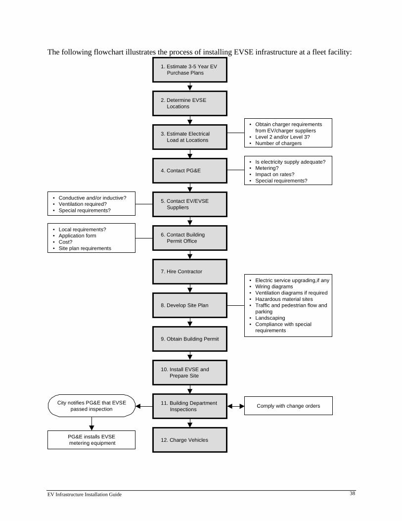
EV Infrastructure Installation Guide 38
The following flowchart illustrates the process of installing EVSE infrastructure at a fleet facility:
2. Determine EVSELocations
3. Estimate ElectricalLoad at Locations
4. Contact PG&E
5. Contact EV/EVSESuppliers
6. Contact BuildingPermit Office
7. Hire Contractor
1. Estimate 3-5 Year EVPurchase Plans
8. Develop Site Plan
9. Obtain Building Permit
10. Install EVSE andPrepare Site
11. Building DepartmentInspections
12. Charge Vehicles
• Conductive and/or inductive?• Ventilation required?• Special requirements?
City notifies PG&E that EVSEpassed inspection
• Local requirements?• Application form• Cost?• Site plan requirements
PG&E installs EVSE metering equipment
• Obtain charger requirementsfrom EV/charger suppliers
• Level 2 and/or Level 3?• Number of chargers
• Is electricity supply adequate?• Metering?• Impact on rates?• Special requirements?
• Electric service upgrading,if any• Wiring diagrams• Ventilation diagrams if required• Hazardous material sites• Traffic and pedestrian flow and
parking• Landscaping• Compliance with special
requirements
Comply with change orders
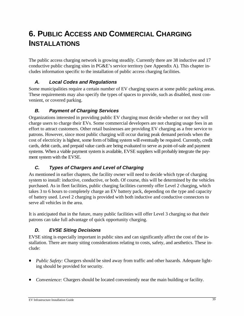
EV Infrastructure Installation Guide 39
6. PUBLIC ACCESS AND COMMERCIAL CHARGINGINSTALLATIONS
The public access charging network is growing steadily. Currently there are 38 inductive and 17conductive public charging sites in PG&E’s service territory (see Appendix A). This chapter in-cludes information specific to the installation of public access charging facilities.
A. Local Codes and RegulationsSome municipalities require a certain number of EV charging spaces at some public parking areas.These requirements may also specify the types of spaces to provide, such as disabled, most con-venient, or covered parking.
B. Payment of Charging ServicesOrganizations interested in providing public EV charging must decide whether or not they willcharge users to charge their EVs. Some commercial developers are not charging usage fees in aneffort to attract customers. Other retail businesses are providing EV charging as a free service topatrons. However, since most public charging will occur during peak demand periods when thecost of electricity is highest, some form of billing system will eventually be required. Currently, creditcards, debit cards, and prepaid value cards are being evaluated to serve as point-of-sale and paymentsystems. When a viable payment system is available, EVSE suppliers will probably integrate the pay-ment system with the EVSE.
C. Types of Chargers and Level of ChargingAs mentioned in earlier chapters, the facility owner will need to decide which type of chargingsystem to install: inductive, conductive, or both. Of course, this will be determined by the vehiclespurchased. As in fleet facilities, public charging facilities currently offer Level 2 charging, whichtakes 3 to 6 hours to completely charge an EV battery pack, depending on the type and capacityof battery used. Level 2 charging is provided with both inductive and conductive connectors toserve all vehicles in the area.
It is anticipated that in the future, many public facilities will offer Level 3 charging so that theirpatrons can take full advantage of quick opportunity charging.
D. EVSE Siting DecisionsEVSE siting is especially important in public sites and can significantly affect the cost of the in-stallation. There are many siting considerations relating to costs, safety, and aesthetics. These in-clude:
x Public Safety: Chargers should be sited away from traffic and other hazards. Adequate light-ing should be provided for security.
x Convenience: Chargers should be located conveniently near the main building or facility.
EV Infrastructure Installation Guide 40
x Proximity to Utility Equipment: Siting charge stations near the electric utility’s feeder lines ortransformers may reduce installation costs.
x Cable Management: To avoid injury from tripping over cables, cords and cables should notcross sidewalks or pedestrian traffic patterns, and should be installed with the EV user's con-venience in mind. Cable retractors should be considered for permanently wired cables.
x Potential Hazards: Ensure that EV charging spaces are not located near potential hazards.EVSE should not be installed near explosive material; flammable vapors, liquids and gases;combustible dust or fibers; and materials which ignite spontaneously on contact with air. NECArticles 500 to 516 describe equipment and procedures for installation of electrical systems inhazardous locations. If charge stands are installed in an enclosed area, check ventilation re-quirements.
x Curbs, Wheel Stops, and Setbacks: Curbs, wheel stops, and setbacks should be provided sothat EVs or other vehicles cannot inadvertently drive into the EVSE. When installing curbs,wheel stops, and setbacks, consider ease of access to the charger, mobility of users and foottraffic in the area.
x Signs and Visibility: The electrical codes require special signs for EVSE (see Figure 7.2).Signs may also be needed to designate parking spaces for EV-use only. These signs should bepositioned high enough to be seen over parked vehicles.
x Disabled Access: See Chapter 3 for more details on disabled access and ADA compliance.
E. Electrical Service AdequacyAs with fleet facilities, the public site owner must determine whether the electrical service is suffi-cient to provide for EV charging. PG&E can help assess the current capacity and needed equip-ment upgrades. In public charging, the facility owner should also plan for the introduction ofLevel 3 charging and its related electrical demands.
F. Electric RatesProperty owners should discuss the impact of EV charging on rates with a PG&E representative.
G. Prevention of VandalismIf the EVSE is situated in an outdoor parking lot, it should be sited to minimize the risk of van-dalism. This includes consideration of lighting, alarms, traffic through the area, visibility from thesecurity gate or desk, and fencing or enclosures.
EV Infrastructure Installation Guide 41
H. LightingPublic charge stations should have enough lighting to create an attractive environment and toprovide safety for late-night charging. Lighting will vary according to the needs of the site andlocal ordinances. In all cases, lighting should promote security of EV drivers, EVs, and EVSE;safe operation of the charging equipment; and the attractiveness of the environment.
I. Creating the Site PlanSimilar to other types of installations, a site plan for engineering review and approval should bedeveloped. A siting plan is necessary for a building permit, which is required for charger installa-tion.
J. Installation CostsThe costs of installing EVSE will vary from site to site. The cost table in the previous chapterprovides sample costs for reference only and is applicable to public access installations. Not allcosts will apply to all sites.
K. Checklist for Public Access and Commercial Charging Installations1. Investigate local requirements for EV charging, including number of spaces required,
types of spaces (disabled, “most convenient,” covered parking, etc.). Also, determinewhether the local jurisdiction, electric utility, or EV/EVSE manufacturer has any specialrequirements.
2. Determine number of spaces to add public-access EVSE.
3. Decide what levels of charging to install.
4. Estimate electrical load.
5. Contact PG&E to discuss adequacy of utility feeder line, equipment, impact of chargingload on electric rates, and proper siting of new utility equipment.
6. Select an electrical contractor and ensure that the contractor's license for electrical work iscurrent.
7. Develop a site plan, including location of hazardous materials; wiring diagrams; trafficflow, parking and landscaping drawings; lists of materials; and ventilation diagram (if ven-tilation is required).
8. Apply for a building permit. Do not begin installation until the permit is issued.
9. Install EVSE (and ventilation, if required).
10. Notify building department that the installation is ready for inspection.
11. Discuss insurance coverage with an insurance agent.
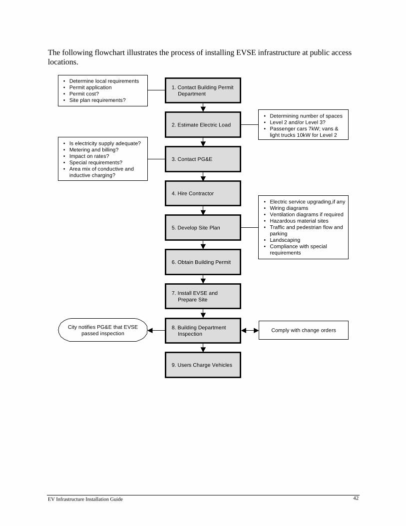
EV Infrastructure Installation Guide 42
The following flowchart illustrates the process of installing EVSE infrastructure at public accesslocations.
2. Estimate Electric Load
3. Contact PG&E
4. Hire Contractor
5. Develop Site Plan
6. Obtain Building Permit
7. Install EVSE andPrepare Site
1. Contact Building PermitDepartment
8. Building DepartmentInspection
9. Users Charge Vehicles
City notifies PG&E that EVSEpassed inspection
• Determining number of spaces• Level 2 and/or Level 3?• Passenger cars 7kW; vans &
light trucks 10kW for Level 2
• Electric service upgrading,if any• Wiring diagrams• Ventilation diagrams if required• Hazardous material sites• Traffic and pedestrian flow and
parking• Landscaping• Compliance with special
requirements
Comply with change orders
• Determine local requirements• Permit application• Permit cost?• Site plan requirements?
• Is electricity supply adequate?• Metering and billing?• Impact on rates?• Special requirements?• Area mix of conductive and
inductive charging?
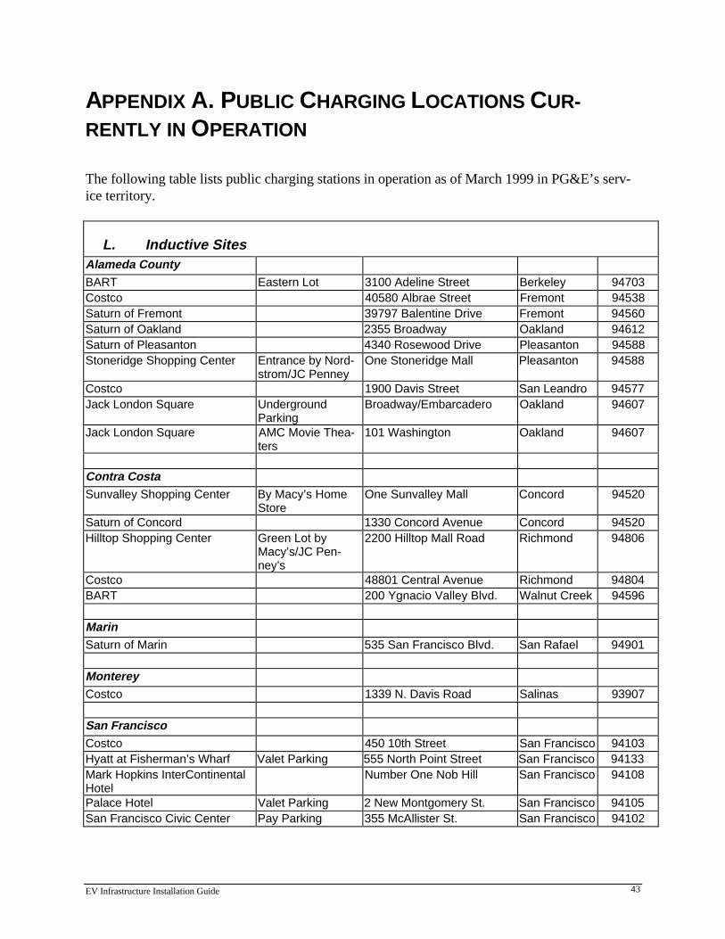
EV Infrastructure Installation Guide 43
APPENDIX A. PUBLIC CHARGING LOCATIONS CUR-RENTLY IN OPERATION
The following table lists public charging stations in operation as of March 1999 in PG&E’s serv-ice territory.
L. Inductive SitesAlameda CountyBART Eastern Lot 3100 Adeline Street Berkeley 94703Costco 40580 Albrae Street Fremont 94538Saturn of Fremont 39797 Balentine Drive Fremont 94560Saturn of Oakland 2355 Broadway Oakland 94612Saturn of Pleasanton 4340 Rosewood Drive Pleasanton 94588Stoneridge Shopping Center Entrance by Nord-
strom/JC PenneyOne Stoneridge Mall Pleasanton 94588
Costco 1900 Davis Street San Leandro 94577Jack London Square Underground
ParkingBroadway/Embarcadero Oakland 94607
Jack London Square AMC Movie Thea-ters
101 Washington Oakland 94607
Contra CostaSunvalley Shopping Center By Macy’s Home
StoreOne Sunvalley Mall Concord 94520
Saturn of Concord 1330 Concord Avenue Concord 94520Hilltop Shopping Center Green Lot by
Macy’s/JC Pen-ney’s
2200 Hilltop Mall Road Richmond 94806
Costco 48801 Central Avenue Richmond 94804BART 200 Ygnacio Valley Blvd. Walnut Creek 94596
MarinSaturn of Marin 535 San Francisco Blvd. San Rafael 94901
MontereyCostco 1339 N. Davis Road Salinas 93907
San FranciscoCostco 450 10th Street San Francisco 94103Hyatt at Fisherman’s Wharf Valet Parking 555 North Point Street San Francisco 94133Mark Hopkins InterContinentalHotel
Number One Nob Hill San Francisco 94108
Palace Hotel Valet Parking 2 New Montgomery St. San Francisco 94105San Francisco Civic Center Pay Parking 355 McAllister St. San Francisco 94102
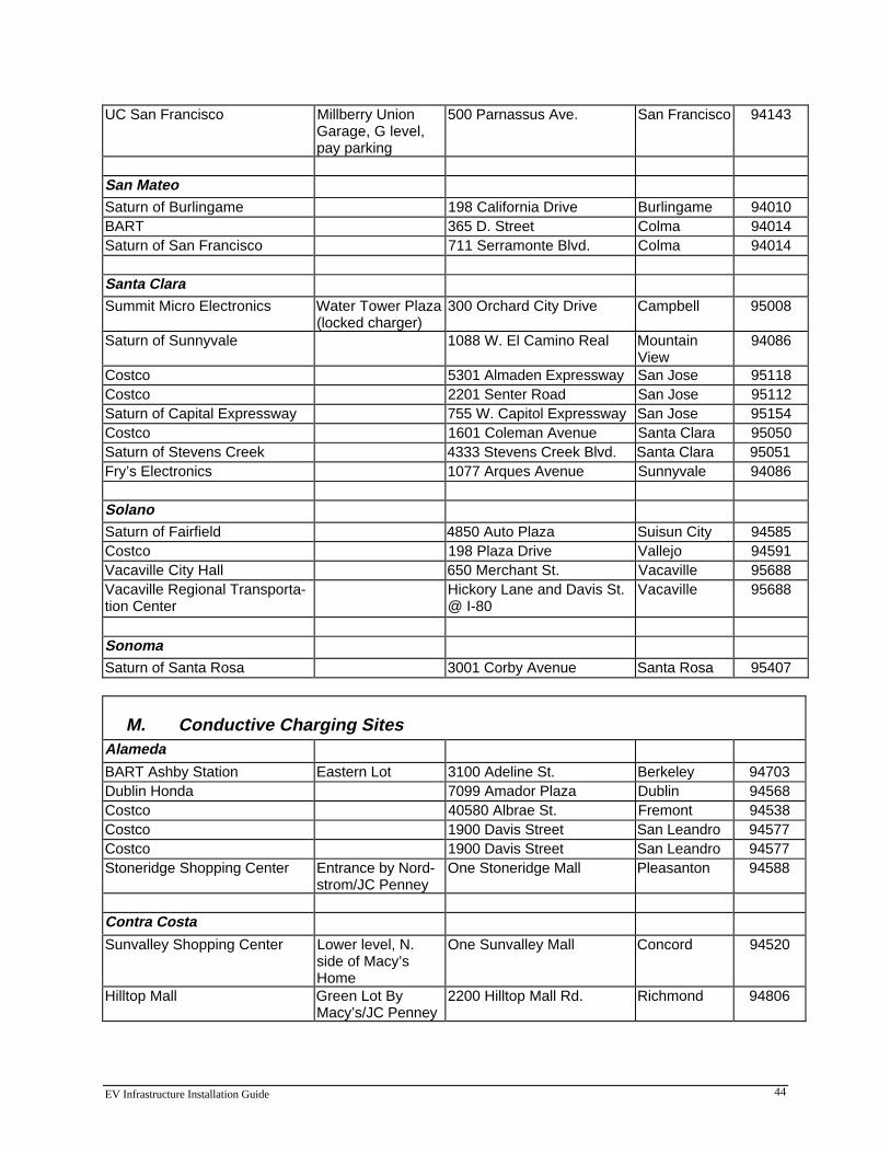
EV Infrastructure Installation Guide 44
UC San Francisco Millberry UnionGarage, G level,pay parking
500 Parnassus Ave. San Francisco 94143
San MateoSaturn of Burlingame 198 California Drive Burlingame 94010BART 365 D. Street Colma 94014Saturn of San Francisco 711 Serramonte Blvd. Colma 94014
Santa ClaraSummit Micro Electronics Water Tower Plaza
(locked charger)300 Orchard City Drive Campbell 95008
Saturn of Sunnyvale 1088 W. El Camino Real MountainView
94086
Costco 5301 Almaden Expressway San Jose 95118Costco 2201 Senter Road San Jose 95112Saturn of Capital Expressway 755 W. Capitol Expressway San Jose 95154Costco 1601 Coleman Avenue Santa Clara 95050Saturn of Stevens Creek 4333 Stevens Creek Blvd. Santa Clara 95051Fry’s Electronics 1077 Arques Avenue Sunnyvale 94086
SolanoSaturn of Fairfield 4850 Auto Plaza Suisun City 94585Costco 198 Plaza Drive Vallejo 94591Vacaville City Hall 650 Merchant St. Vacaville 95688Vacaville Regional Transporta-tion Center
Hickory Lane and Davis St.@ I-80
Vacaville 95688
SonomaSaturn of Santa Rosa 3001 Corby Avenue Santa Rosa 95407
M. Conductive Charging SitesAlameda
BART Ashby Station Eastern Lot 3100 Adeline St. Berkeley 94703Dublin Honda 7099 Amador Plaza Dublin 94568Costco 40580 Albrae St. Fremont 94538Costco 1900 Davis Street San Leandro 94577Costco 1900 Davis Street San Leandro 94577Stoneridge Shopping Center Entrance by Nord-
strom/JC PenneyOne Stoneridge Mall Pleasanton 94588
Contra Costa
Sunvalley Shopping Center Lower level, N.side of Macy’sHome
One Sunvalley Mall Concord 94520
Hilltop Mall Green Lot ByMacy’s/JC Penney
2200 Hilltop Mall Rd. Richmond 94806
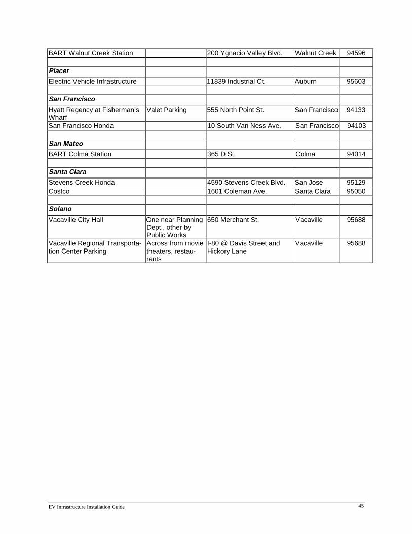
EV Infrastructure Installation Guide 45
BART Walnut Creek Station 200 Ygnacio Valley Blvd. Walnut Creek 94596
Placer
Electric Vehicle Infrastructure 11839 Industrial Ct. Auburn 95603
San Francisco
Hyatt Regency at Fisherman’sWharf
Valet Parking 555 North Point St. San Francisco 94133
San Francisco Honda 10 South Van Ness Ave. San Francisco 94103
San Mateo
BART Colma Station 365 D St. Colma 94014
Santa Clara
Stevens Creek Honda 4590 Stevens Creek Blvd. San Jose 95129Costco 1601 Coleman Ave. Santa Clara 95050
Solano
Vacaville City Hall One near PlanningDept., other byPublic Works
650 Merchant St. Vacaville 95688
Vacaville Regional Transporta-tion Center Parking
Across from movietheaters, restau-rants
I-80 @ Davis Street andHickory Lane
Vacaville 95688

EV Infrastructure Installation Guide 46
APPENDIX B. BUILDING CODE CONTACTS IN MAJORCITIES
City Contact Phone NumberBakersfield Building Inspections Dept. 805-326-3720Fresno Electrical Inspections Dept. 559-498-2626Modesto Building Inspection Depart-
ment209-577-5232
Oakland Calvin Wong, Electrical In-spector
510-238-4794
San Francisco Frank Fong, Electrical In-spector
415-558-6030
San Jose Joseph Boody, Electrical In-spector
408-277-4541
Stockton George Davis, Electrical In-spector
209-937-8637
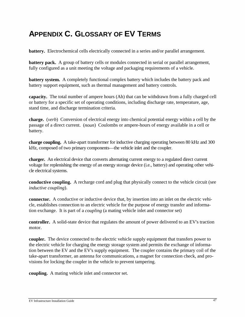
EV Infrastructure Installation Guide 47
APPENDIX C. GLOSSARY OF EV TERMS
battery. Electrochemical cells electrically connected in a series and/or parallel arrangement.
battery pack. A group of battery cells or modules connected in serial or parallel arrangement,fully configured as a unit meeting the voltage and packaging requirements of a vehicle.
battery system. A completely functional complex battery which includes the battery pack andbattery support equipment, such as thermal management and battery controls.
capacity. The total number of ampere hours (Ah) that can be withdrawn from a fully charged cellor battery for a specific set of operating conditions, including discharge rate, temperature, age,stand time, and discharge termination criteria.
charge. (verb) Conversion of electrical energy into chemical potential energy within a cell by thepassage of a direct current. (noun) Coulombs or ampere-hours of energy available in a cell orbattery.
charge coupling. A take-apart transformer for inductive charging operating between 80 kHz and 300kHz, composed of two primary components—the vehicle inlet and the coupler.
charger. An electrical device that converts alternating current energy to a regulated direct currentvoltage for replenishing the energy of an energy storage device (i.e., battery) and operating other vehi-cle electrical systems.
conductive coupling. A recharge cord and plug that physically connect to the vehicle circuit (seeinductive coupling).
connector. A conductive or inductive device that, by insertion into an inlet on the electric vehi-cle, establishes connection to an electric vehicle for the purpose of energy transfer and informa-tion exchange. It is part of a coupling (a mating vehicle inlet and connector set)
controller. A solid-state device that regulates the amount of power delivered to an EV's tractionmotor.
coupler. The device connected to the electric vehicle supply equipment that transfers power tothe electric vehicle for charging the energy storage system and permits the exchange of informa-tion between the EV and the EV's supply equipment. The coupler contains the primary coil of thetake-apart transformer, an antenna for communications, a magnet for connection check, and pro-visions for locking the coupler in the vehicle to prevent tampering.
coupling. A mating vehicle inlet and connector set.
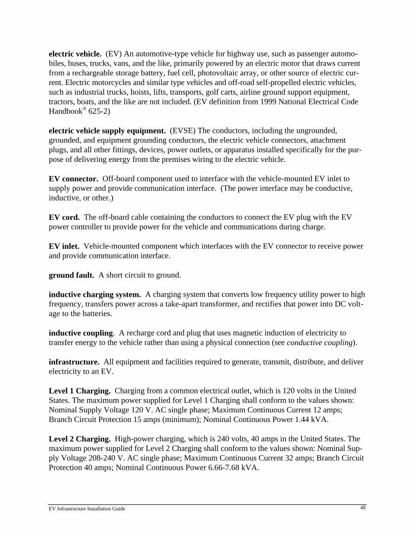
EV Infrastructure Installation Guide 48
electric vehicle. (EV) An automotive-type vehicle for highway use, such as passenger automo-biles, buses, trucks, vans, and the like, primarily powered by an electric motor that draws currentfrom a rechargeable storage battery, fuel cell, photovoltaic array, or other source of electric cur-rent. Electric motorcycles and similar type vehicles and off-road self-propelled electric vehicles,such as industrial trucks, hoists, lifts, transports, golf carts, airline ground support equipment,tractors, boats, and the like are not included. (EV definition from 1999 National Electrical CodeHandbook® 625-2)
electric vehicle supply equipment. (EVSE) The conductors, including the ungrounded,grounded, and equipment grounding conductors, the electric vehicle connectors, attachmentplugs, and all other fittings, devices, power outlets, or apparatus installed specifically for the pur-pose of delivering energy from the premises wiring to the electric vehicle.
EV connector. Off-board component used to interface with the vehicle-mounted EV inlet tosupply power and provide communication interface. (The power interface may be conductive,inductive, or other.)
EV cord. The off-board cable containing the conductors to connect the EV plug with the EVpower controller to provide power for the vehicle and communications during charge.
EV inlet. Vehicle-mounted component which interfaces with the EV connector to receive powerand provide communication interface.
ground fault. A short circuit to ground.
inductive charging system. A charging system that converts low frequency utility power to highfrequency, transfers power across a take-apart transformer, and rectifies that power into DC volt-age to the batteries.
inductive coupling. A recharge cord and plug that uses magnetic induction of electricity totransfer energy to the vehicle rather than using a physical connection (see conductive coupling).
infrastructure. All equipment and facilities required to generate, transmit, distribute, and deliverelectricity to an EV.
Level 1 Charging. Charging from a common electrical outlet, which is 120 volts in the UnitedStates. The maximum power supplied for Level 1 Charging shall conform to the values shown:Nominal Supply Voltage 120 V. AC single phase; Maximum Continuous Current 12 amps;Branch Circuit Protection 15 amps (minimum); Nominal Continuous Power 1.44 kVA.
Level 2 Charging. High-power charging, which is 240 volts, 40 amps in the United States. Themaximum power supplied for Level 2 Charging shall conform to the values shown: Nominal Sup-ply Voltage 208-240 V. AC single phase; Maximum Continuous Current 32 amps; Branch CircuitProtection 40 amps; Nominal Continuous Power 6.66-7.68 kVA.

EV Infrastructure Installation Guide 49
Level 3 Charging. Fast charging at 480 volts, 400 amps with three-phase power. This energytransfer method utilizes dedicated electric vehicle supply equipment capable of replenishing morethan half of the capacity of an EV battery as quickly as in ten minutes. With this method, theelectric vehicle accepts dc energy from an off-board power supply. The maximum power suppliedfor Level 3 charging equipment conforms to these values: Nominal Supply Voltage 600 V dc(maximum); Maximum Continuous Current 400 amps; Branch Circuit Protection As Required;Nominal Continuous Power 160 kW dc.
off-board charger. A charger with the intelligence and control in the charger stand, not on thevehicle.
on-board charger. A charger with the intelligence and control on the vehicle, not in the chargerstand.
range. The maximum distance that an electric vehicle can travel on a single battery charge over aspecified driving cycle to the battery manufacturer’s recommended maximum discharge level.Alternatively, the distance reached when a specified minimum level of performance or other char-acteristic (such as battery depth of discharge) is attained.
time-of-use (TOU) rates. Discounted electricity rates established by utilities to encourage use ofelectricity during off-peak hours.
vehicle inlet. The device on the electric vehicle into which the connector is inserted for energytransfer and information exchange. This is part of the charge coupling.
EV Infrastructure Installation Guide 50
APPENDIX D. REFERENCES
1998 California Electrical Code. California Building Standards Commission, December 1998.
EV Buyers Guide, California Energy Commission, Sacramento, March 1996.
EV Fleet Infrastructure Planning Guide. Electric Power Research Institute, TR-110702. 1998.
Electric Vehicle Charging Facility Installation Guidelines. Southern California Edison Co., 1996.
Electric Vehicle Community Market Launch Manual, Vol. II: Infrastructure, Electric Transpor-tation Coalition et al., Washington, D.C., December 1995.
Electric Vehicle Resource Guide. U.S. Department of Energy, Office of Transportation Tech-nologies. July 1998.
NEC¤ Changes 1999, M.W. Early, M.C. Ode, J.S. Sargent, D. Strube, N. Williams. NationalFire Protection Association, Quincy, MA, 1998.
National Electrical Code 1999 Electronic Edition, National Fire Protection Association, Quincy,MA, 1998.