Embed Size (px)
Citation preview

• Electric Vehicle Charging Equipment
Module #2 Electric Vehicle Charging Equipment ‐Module Sections
2.1 – Charging Equipment Introduction2.2 – AC EVSE2.3 – DC Charging 2.4 – Wireless Charging 2.5 – EVSE Communications and Networks
EVITP V4.0 Module #2 2
Seattle, WA - Photo courtesy of Ryan Bradt

EVITP V4.0 Module #2 3
Module 2 – Section 1

2.1 – Charging Equipment IntroductionOverviewSection 2.1 introduces the various types of equipment that can be used to charge or supply power to Electric Vehicles (EVs). Charging equipment can supply Alternating Current (AC) to a vehicle which is converted to Direct Current (DC) to charge the battery, or supply DC directly to a vehicle’s battery. Charging equipment can transfer power either via direct coupling (cord and plug) or wirelessly (induction).
EVITP V4.0 Module #2 – Section 1 4
NW WA Electrical JATC EVSE Lab - Photo courtesy of Ryan Bradt
2.1 – Charging Equipment Learning objectives
Upon completion of this section, students should be able to…• Demonstrate awareness of the various terminologies (terms) used throughout the EV industry to describe equipment used to supply energy to EV batteries.
• Understand the development of early EV charging equipment.• Describe the difference between AC Electric Vehicle Supply Equipment (EVSE) and DC electric vehicle charging equipment.
EVITP V4.0 Module #2 – Section 1 5
2.1 – Charging EquipmentEV Charging Equipment Terms!
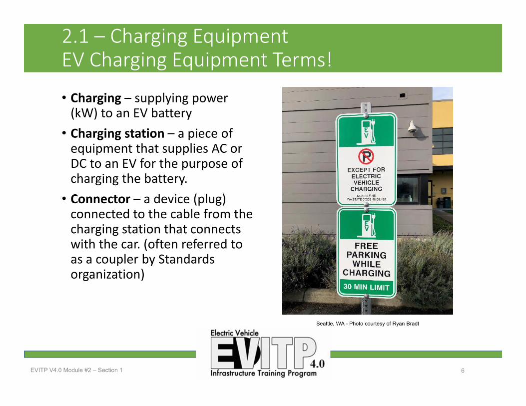
• Charging – supplying power (kW) to an EV battery
• Charging station – a piece of equipment that supplies AC or DC to an EV for the purpose of charging the battery.
• Connector – a device (plug) connected to the cable from the charging station that connects with the car. (often referred to as a coupler by Standards organization)
EVITP V4.0 Module #2 – Section 1 6
Seattle, WA - Photo courtesy of Ryan Bradt

2.1 – Charging EquipmentEV Charging Equipment Acronyms!
• EVCS – Electric Vehicle Charging Station
• EVSE – Electric Vehicle Supply Equipment
• EVSP – Electric Vehicle Service Provider
• NRTL – Nationally Recognized Testing Laboratory ( e.g., UL & ETL)
• SOC – State Of Charge
EVITP V4.0 Module #2 – Section 1 7
Everett, WA - Photo courtesy of Ryan Bradt

2.1 – Charging Equipment Historical Perspective
• EVs have been available to consumers in some form for as long as Internal Combustion Engine (ICE) vehicles, with EVs came the need to charge.
• Early EV charging was for 12‐110VDC batteries requiring an external charger.
• Chargers later moved inside the EV converting AC to DC be used in charging the battery.
EVITP V4.0 Module #2 = Section 1 8
Seattle, WA - Photo courtesy of the Seattle City Light, 1973

2.1 – Charging Equipment Historical Perspective
EVITP V4.0 Module #2 – Section 1 9
• The 1911 Baker Electric came with 12 six volt batteries that produced 72 volts DC.
• The General Electric Arc rectifier was used to charge the batteries.
Photos taken at the American Car Museum Tacoma, WA Courtesy of Ryan Bradt

2.1 – Charging Equipment What is EVSE?
• EVSE provides a safe connection from the electrical source to the plug connected to the EV.
• EVSE provides several safety features including: ground fault circuit interruption (GFCI), ground verification, and safety lock‐out de‐energizing when the cable is not properly connected to the EV.
• EVSE detects hardware faults, disconnecting power and preventing vehicle and battery damage.
EVITP V4.0 Module #2 – Section 1 10
Wenatchee, WA - Photo courtesy of Ryan Bradt
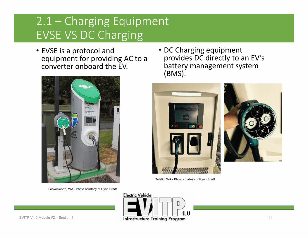
2.1 – Charging Equipment EVSE VS DC Charging• EVSE is a protocol and equipment for providing AC to a converter onboard the EV.
• DC Charging equipment provides DC directly to an EV’s battery management system (BMS).
EVITP V4.0 Module #2 – Section 1 11
Leavenworth, WA - Photo courtesy of Ryan Bradt
Tulalip, WA - Photo courtesy of Ryan Bradt

2.1 – Charging Equipment ‐ Questions?
EVITP V4.0 Module #2 – Section 1 12
Stevens Pass Ski Resort, WA - Photo courtesy of Ryan Bradt

EVITP V4.0 Module #2 13
Module 2 – Section 3
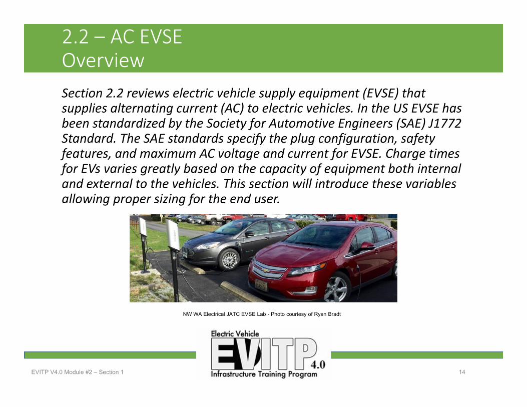
Section 2.2 reviews electric vehicle supply equipment (EVSE) that supplies alternating current (AC) to electric vehicles. In the US EVSE has been standardized by the Society for Automotive Engineers (SAE) J1772 Standard. The SAE standards specify the plug configuration, safety features, and maximum AC voltage and current for EVSE. Charge times for EVs varies greatly based on the capacity of equipment both internal and external to the vehicles. This section will introduce these variables allowing proper sizing for the end user.
EVITP V4.0 Module #2 – Section 1 14
2.2 – AC EVSEOverview
NW WA Electrical JATC EVSE Lab - Photo courtesy of Ryan Bradt
Upon completion of this section, students should be able to…• Explain the importance of the EVSE safety features required by the SAE standards and how they function.
• Classify the levels of EVSE specified by AC voltage and current levels. • Diagram the pin configuration of the J1772 Standard and explain the purpose of the pins in the charging of an EV.
• Define the variables that determine the required charge time for an EV.
EVITP V4.0 Module #2 – Section 2 15
2.2 – AC EVSE Learning Objectives

2.2 – AC EVSEEVSE AC output, Level 1 & 2 AC Level 1• 120V AC, 1‐phase• 12‐16 amps – continuous• 1.44 – 1.92kW
AC Level 2• 208/240V AC, 1‐phase• Up to 80 amps – continuous• Up to 19.2kW
EVITP V4.0 Module #2 – Section 2 16
Photo courtesy of Ryan Bradt Renton, WA - Photo courtesy of Ryan Bradt
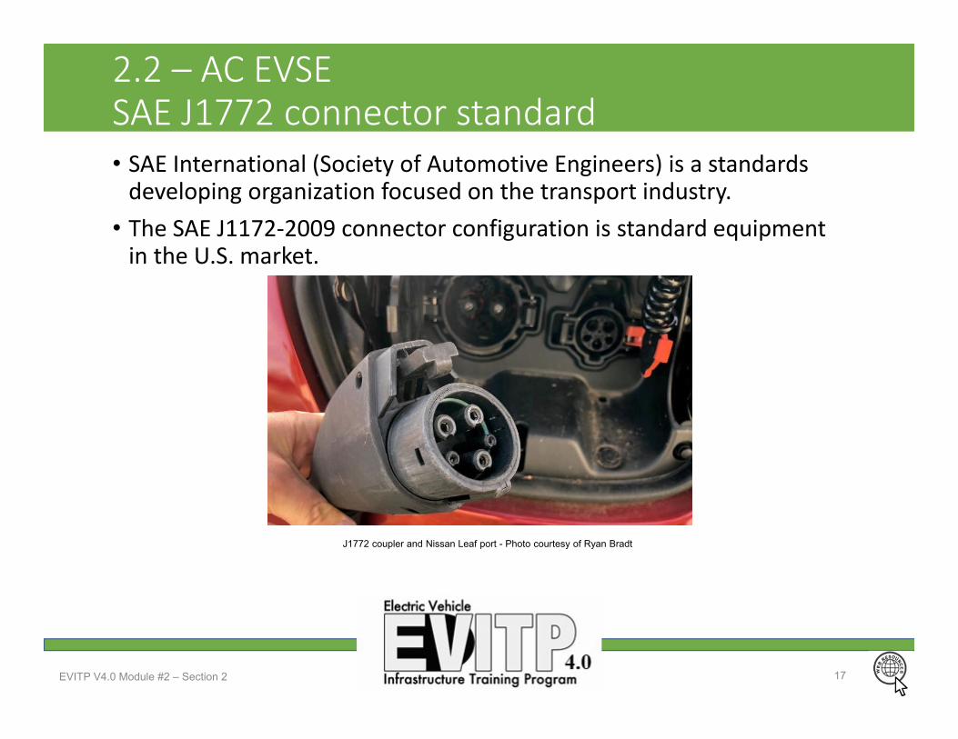
2.2 – AC EVSESAE J1772 connector standard• SAE International (Society of Automotive Engineers) is a standards developing organization focused on the transport industry.
• The SAE J1172‐2009 connector configuration is standard equipment in the U.S. market.
EVITP V4.0 Module #2 – Section 2 17
J1772 coupler and Nissan Leaf port - Photo courtesy of Ryan Bradt

2.2 – AC EVSESAE J1772 Coupler Configuration
EVITP V4.0 Module #2 – Section 2 18
Line 1
ProximityEquipment GroundControl Pilot
Line 2 / Neutral
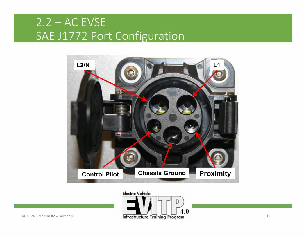
2.2 – AC EVSESAE J1772 Port Configuration
EVITP V4.0 Module #2 – Section 2 19
L2/N
ProximityChassis Ground
L1
Control Pilot

2.2 – AC EVSESAE J1772 Proximity• The proximity connection point is used to communicate between the EV and the EVSE to insure proper connection of the EVSE to the EV.
• When the EVSE detects the proper resistance value at the proximity point is allows contactor closure.
• This safety feature assures no energy is present at the EVSE coupler without proper connection to the EV.
EVITP V4.0 Module #2 – Section 2 20
Photo courtesy of Ryan Bradt

2.2 – AC EVSESAE J1772 Pilot Signal
• The voltage present pilot terminal defines the state of the EVSE
• The J1772 pilot uses a 1kHz +12V to ‐12V square wave signal
• The EVSE changes state according to the voltage present
EVITP V4.0 Module #2 – Section 2 21
State Pilot High Pilot Low Frequency EV Resistance DescriptionA +12V N/A DC N/A Not ConnectedB +9V ‐12V 1kHz 2.74k EV Connected (Ready)C +6V ‐12V 1kHz 882 EV ChargeD +3V ‐12V 1kHz 246 EV Charge Vent. RequiredE +0V +0V N/A ErrorF N/A ‐12V N/A Unknown/Error
Photo courtesy of Ryan Bradt

Two factors determine the maximum power (kW) that can be delivered to a EVs battery from EVSE.1. The voltage/amperage supplied to the EVSE determines the power
output that the EVSE can deliver to vehicle. 2. The vehicle's converter has a maximum power capacity.
EVITP V4.0 Module #2 – Section 2 22
2.2 – AC EVSESAE J1772 Charging time variables
Level 1
Level 2
CommercialLevel 2
Electric Vehicle Converter/
Onboard Charger
120VAC
240VAC
208-240VAC
120VAC
240VAC
208-240VAC

2.2 – AC EVSESAE J1772 Charging time variables
EVSE kW capacity Voltage Amperage Branch Circuit Required
1.4kW 120V 11.66A 15A
3.3kW 208V 15.86A 20A
7.2kW 208V 34.61A 40A
7.2kW 240V 30A 40A
19.2kW 240V 80A 80A (MAX per SAE)
EVITP V4.0 Module #2 – Section 2 23
• EVSE are available with different levels of power delivery • The EVs power acceptance rate should be considered when making purchasing decisions.
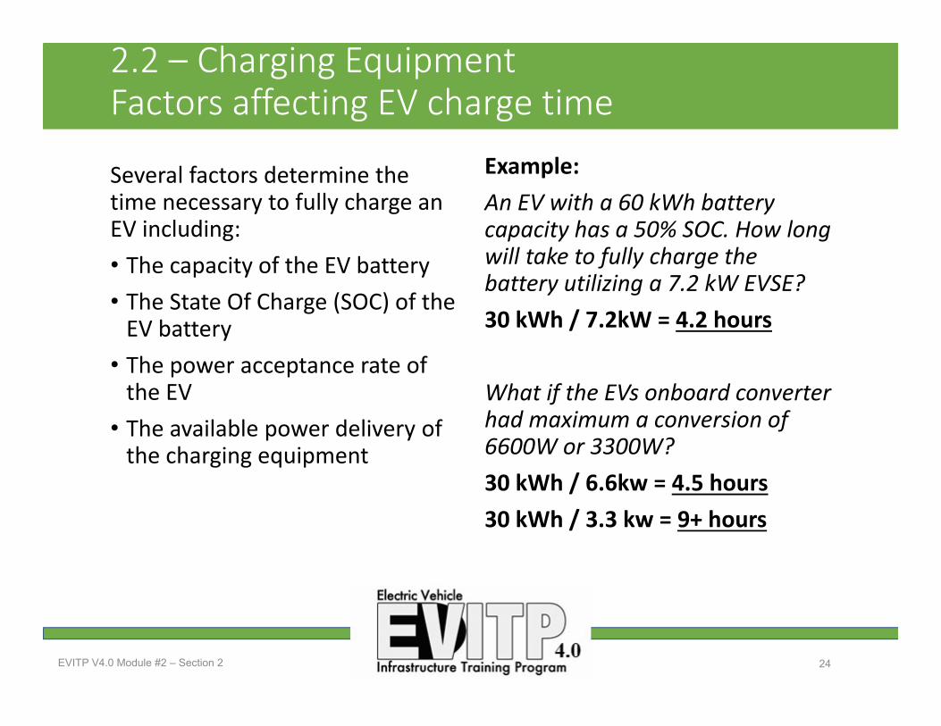
2.2 – Charging EquipmentFactors affecting EV charge time
Several factors determine the time necessary to fully charge an EV including: • The capacity of the EV battery • The State Of Charge (SOC) of the EV battery
• The power acceptance rate of the EV
• The available power delivery of the charging equipment
Example: An EV with a 60 kWh battery capacity has a 50% SOC. How long will take to fully charge the battery utilizing a 7.2 kW EVSE? 30 kWh / 7.2kW = 4.2 hours
What if the EVs onboard converter had maximum a conversion of 6600W or 3300W?30 kWh / 6.6kw = 4.5 hours30 kWh / 3.3 kw = 9+ hours
EVITP V4.0 Module #2 – Section 2 24

2.2 – AC EVSEManufacturers – ClipperCreek (sample)
EVITP V4.0 Module #2 – Section 2 25
Photos courtesy of ClipperCreek

2.2 – AC EVSE – Questions?
EVITP V4.0 Module #2 – Section 2 26
Puget Sound Electrical JATC, Renton, WA - Photo courtesy of Ryan Bradt

EVITP V4.0 Module #2 27
Module 2 – Section 3
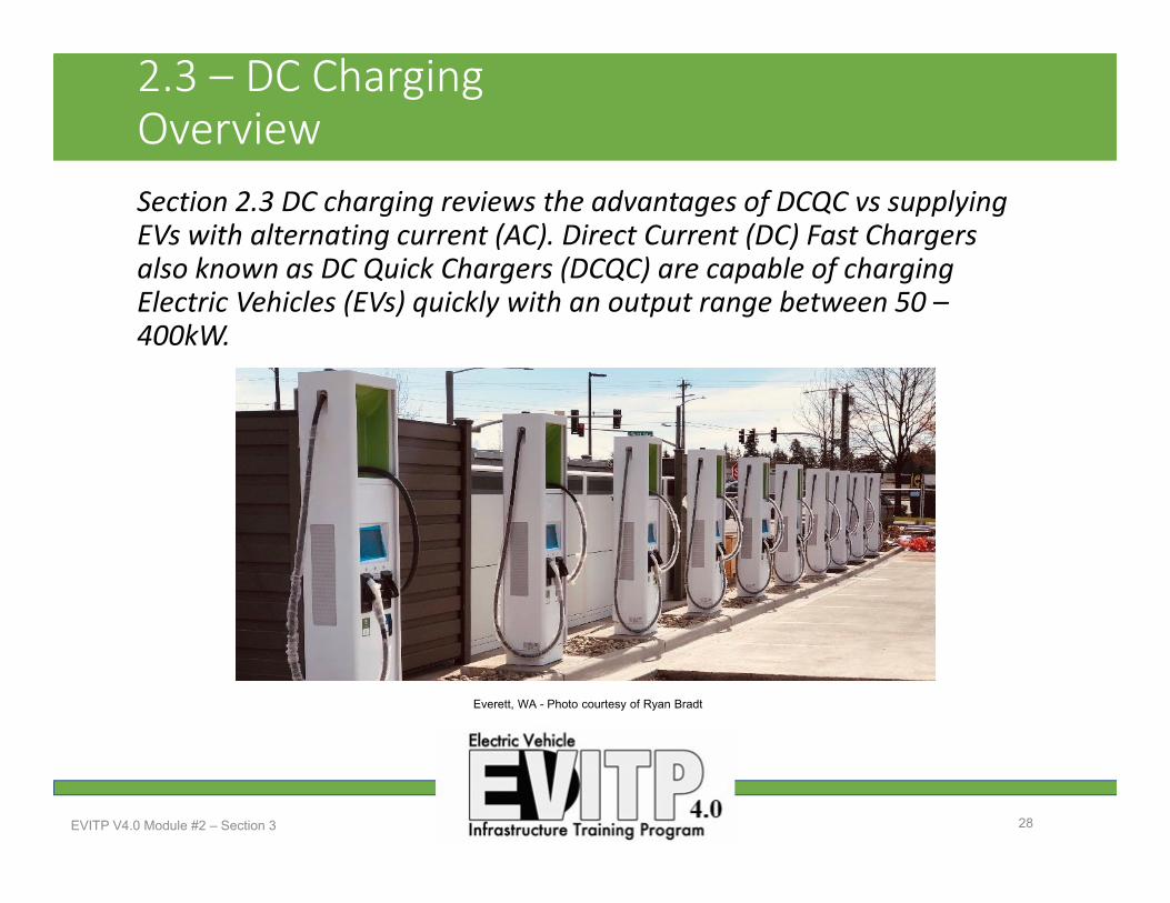
2.3 – DC ChargingOverviewSection 2.3 DC charging reviews the advantages of DCQC vs supplying EVs with alternating current (AC). Direct Current (DC) Fast Chargers also known as DC Quick Chargers (DCQC) are capable of charging Electric Vehicles (EVs) quickly with an output range between 50 –400kW.
EVITP V4.0 Module #2 – Section 3 28
Everett, WA - Photo courtesy of Ryan Bradt
2.3 – DC Charging Learning objectives
Upon completion of this section, students should be able to…• Describe the various types and sizes of DC charging equipment available in the marketplace.
• Define the safety feature of DC charging equipment. • Identify the difference between the various DC charging equipment connector configurations.
• Understand the AC voltage and current requirements of DC charging equipment for proper service load calculations.
• Be aware of the load created by electrical vehicle charging equipment on a buildings service and serving utilities.
EVITP V4.0 Module #2 – Section 3 29

2.3 – DC Charging Introduction
DC Chargers…• offer considerably more power than the current generation of AC Chargers (EVSE).
• are not limited by capacity of the vehicle’s converter to rectify AC to DC.
• are capable of charging many of todays EVs in 30 minutes or less!
• require a large three phase supply of 200 ‐ 400A at 208 or 480V
EVITP V4.0 Module #2 – Section 3 30
Seattle, WA - Photo courtesy of Ryan Bradt

2.3 – DC ChargingStandards
Three competing standards in the U.S.• CHAdeMO• J1772 CCS (combination)• Tesla Supercharging ‐Proprietary
• Many others worldwide
EVITP V4.0 Module #2 – Section 3 31
Anaheim, CA - Photo courtesy of Ryan Bradt

2.3 – DC Charging CHAdeMO
• CHAdeMO is the name of a DC charging standard developed by JARI (Japan Automobile Research Institute) and TEPCO (Tokyo Electric Power Company)
• Delivers up to 62.5 kW of high voltage DC at 500VDC, up to 125A
• CHAdeMO is an abbreviation of "CHArge de MOve“
EVITP V4.0 Module #2 = Section 3 32
Renton, WA - Photo courtesy of Ryan Bradt

2.3 – DC Charging CHAdeMo coupler configuration
EVITP V4.0 Module #2 – Section 3 33
56
12
43
789
10
Pin # Function1 Reference ground2 Control EV Relay (1 of 2)3 not assigned4 Ready to Charge5 DC Negative6 DC Positive7 Proximity Detection8 Communication +9 Communication ‐10 Control EV Relay (2 of 2)
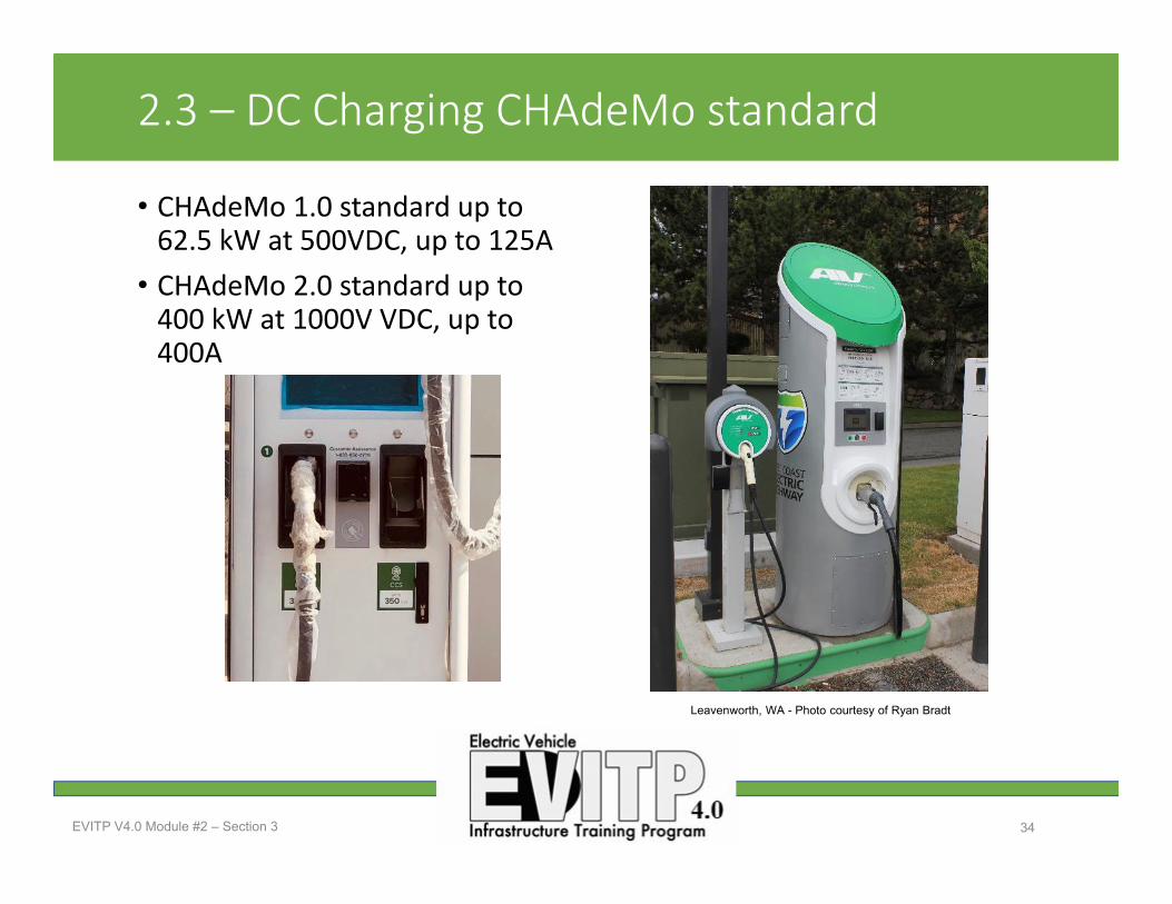
2.3 – DC Charging CHAdeMo standard
• CHAdeMo 1.0 standard up to 62.5 kW at 500VDC, up to 125A
• CHAdeMo 2.0 standard up to 400 kW at 1000V VDC, up to 400A
EVITP V4.0 Module #2 – Section 3 34
Leavenworth, WA - Photo courtesy of Ryan Bradt
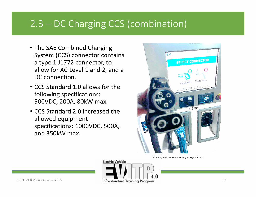
2.3 – DC Charging CCS (combination)
• The SAE Combined Charging System (CCS) connector contains a type 1 J1772 connector, to allow for AC Level 1 and 2, and a DC connection.
• CCS Standard 1.0 allows for the following specifications: 500VDC, 200A, 80kW max.
• CCS Standard 2.0 increased the allowed equipment specifications: 1000VDC, 500A, and 350kW max.
EVITP V4.0 Module #2 – Section 3 35
Renton, WA - Photo courtesy of Ryan Bradt

2.3 – DC Charging Tesla
• Tesla Superchargers utilize a proprietary connector only compatible with Tesla EVs.
• Current Superchargers can provide a maximum of 120 kW per EV.
• As of 2018, Tesla operates 7,320 superchargers in 1,063 stations worldwide including 443 stations in the U.S. and 31 in Canada.
EVITP V4.0 Module #2 – Section 3 36
Photos courtesy of Ryan Bradt

2.3 – DC ChargingCharging Cable Technology – High‐Power Charging(HPC)
• Charging currents up to 200A have been technically possible with conventional cables and connectors.
• Higher currents (up to 500A) is being demanded by the industry. A conventional cable and connector at these current levels would overheat or extremely large cable and connectors would be required.
• Solutions: • Liquid cooled cables – circulating a coolant through the cable
• Passive cable cooling ‐ using ambient air and fan
• Active cable cooling ‐ using a refrigeration compressor
EVITP V4.0 Module #2 – Section 3 37

2.3 – DC ChargingLoad on electrical service• AC and DC charging of EVs requires a significant amount of power.
• EV charging equipment may represent the largest load on a buildings electrical service.
• EVSE level 1 = 1.4kW – 1.9kW• EVSE level 2 = up to 19.2kW• DC fast charger CCS Standard 2.0 = 350kW
• DC fast charger CHAdeMoStandard 2.0 = 400kW.
EVITP V4.0 Module #2 – Section 3 38
Mount Vernon, WA - Photo courtesy of Ryan Bradt
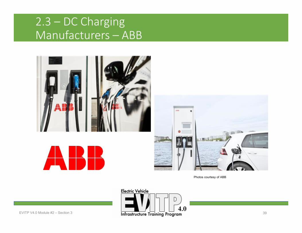
2.3 – DC ChargingManufacturers – ABB
EVITP V4.0 Module #2 – Section 3 39
Photos courtesy of ABB
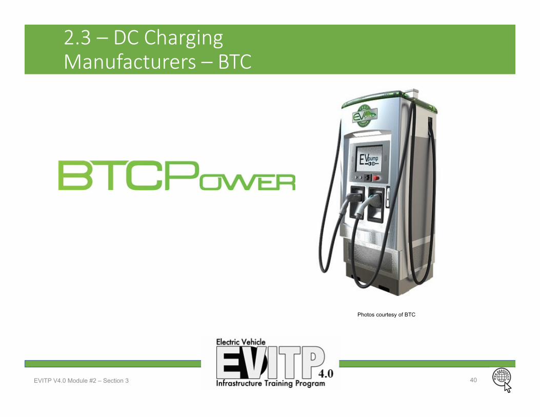
2.3 – DC ChargingManufacturers – BTC
EVITP V4.0 Module #2 – Section 3 40
Photos courtesy of BTC

2.3 – DC ChargingManufacturers – Efacec
EVITP V4.0 Module #2 – Section 3 41
Photos courtesy of efaces
2.3 – DC ChargingManufacturers – Delta
EVITP V4.0 Module #2 – Section 3 42
Photos courtesy of Delta
2.3 – DC ChargingQuestions?
EVITP V4.0 Module #2 – Section 3 43
Seattle, WA - Photo courtesy of Ryan Bradt
EVITP V4.0 Module #2 44
Module 2 – Section 4
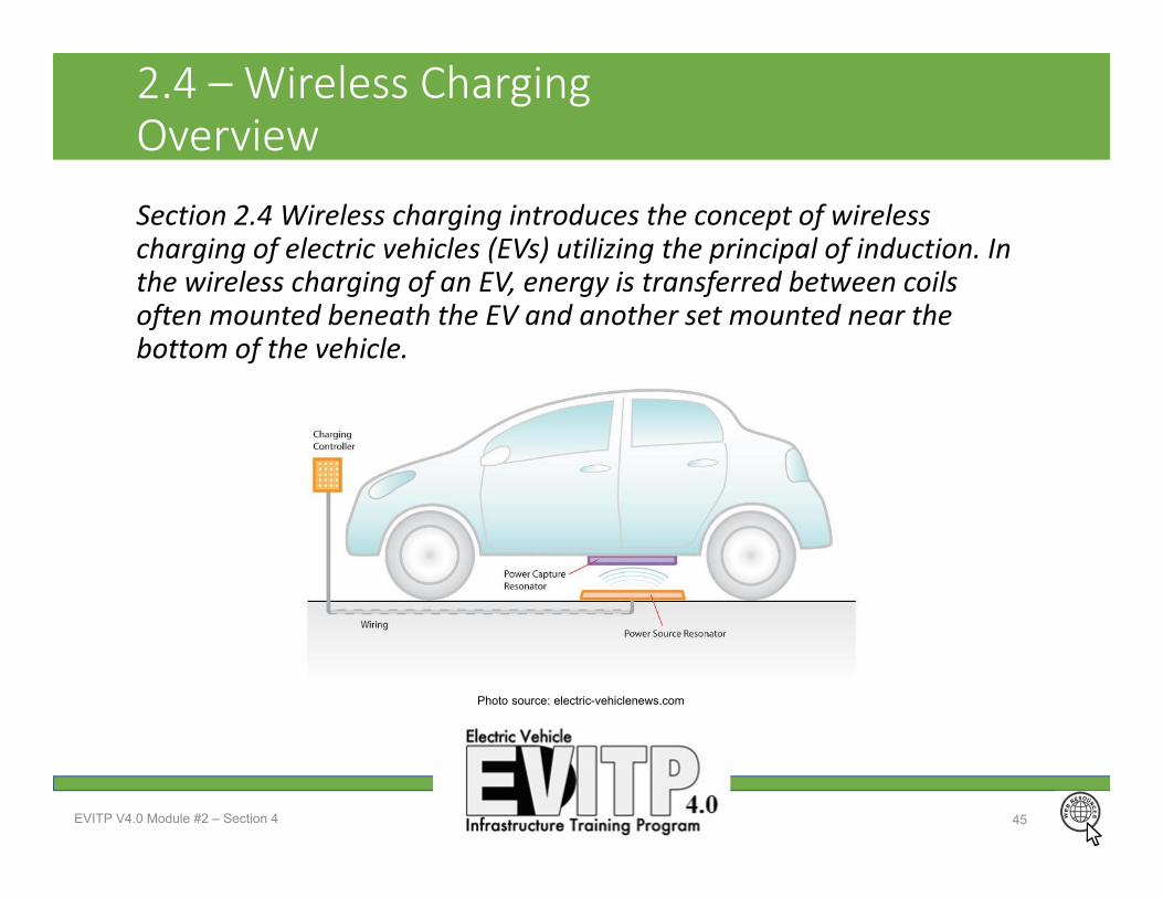
2.4 – Wireless Charging Overview
Section 2.4 Wireless charging introduces the concept of wireless charging of electric vehicles (EVs) utilizing the principal of induction. In the wireless charging of an EV, energy is transferred between coils often mounted beneath the EV and another set mounted near the bottom of the vehicle.
EVITP V4.0 Module #2 – Section 4 45
Photo source: electric-vehiclenews.com

2.4 – Wireless ChargingLearning Objectives
Upon completion of this section, students should be able to…• Understand the difference between wireless EV charging and traditional coupled (conductive) charging.
• Define the key components of wireless EV charging equipment and purpose.
• Explain the benefits and drawbacks of wireless charging. • Recognize wireless charging as an up and coming technology still in development.
EVITP V4.0 Module #2 – Section 4 46
2.4 – Wireless ChargingWhat is wireless charging?
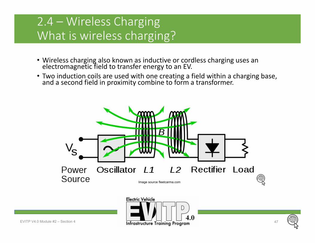
• Wireless charging also known as inductive or cordless charging uses an electromagnetic field to transfer energy to an EV.
• Two induction coils are used with one creating a field within a charging base, and a second field in proximity combine to form a transformer.
EVITP V4.0 Module #2 – Section 4 47
Image source fleetcarma.com

2.4 – Wireless ChargingEquipment components
Wireless charging requires the following key components• EV mounted coil (Power Capture)• Ground mounted surface or imbedded power source coil (Power Source) • Charging controller
EVITP V4.0 Module #2 – Section 4 48
Photo source: electric-vehiclenews.com

2.4 – Wireless ChargingWireless charging pros and cons Advantages• Protected connection – no corrosion
• Durability with no required contact points to break down with connection cycles.
• Reduction in electrical faults with no exposed contact points
• Convenience and safety with with no cables
• Aesthetic quality• Higher reliability
Disadvantages• More expensive• Availability ‐ few EVs in the market are currently wireless charging ready, requiring conversion
• Efficiency losses from inductive charging is around 5% greater than direct coupled EVSE
• Compatibility standards are still being developed.
• Health effects require more study
EVITP V4.0 Module #2 – Section 4 49

2.4 – Wireless ChargingWireless charging standard development
• The SAE has released a new wireless charging specification J2954 Recommended Practice (RP)
• The recommended practice includes specifications for:
• Up to 11kW wireless charging• Magnetic triangulation for vehicle alignment
• Coupled with communication to allow for payment without physical interaction
• Ground clearance up to 250mm (10 inches)
EVITP V4.0 Module #2 – Section 4 50
Photo source: Plugless Power media kit
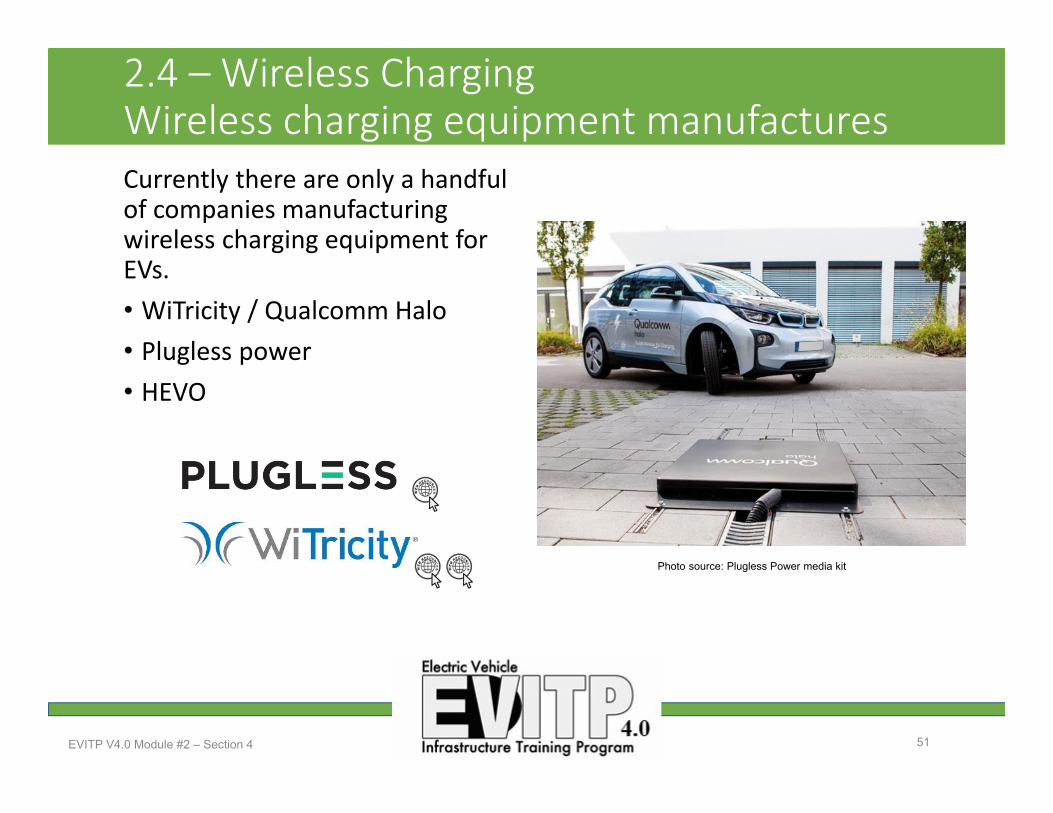
2.4 – Wireless ChargingWireless charging equipment manufacturesCurrently there are only a handful of companies manufacturing wireless charging equipment for EVs. • WiTricity / Qualcomm Halo• Plugless power• HEVO
EVITP V4.0 Module #2 – Section 4 51
Photo source: Plugless Power media kit
2.4 – Wireless ChargingQuestions?
EVITP V4.0 Module #2 – Section 4 52

EVITP V4.0 Module #2 53
Module 2 – Section 5

2.5 – Network and EVSE CommunicationsOverviewElectric Vehicle (EV) owners requiring a charge when away from home generally turn to a public charging station. Public charging stations are readily available with both Electric Vehicle Supply Equipment (EVSE) supplying Alternating Current (AC) to the vehicle as well as Direct Current (DC) charging stations. An EV network is an infrastructure system of
EVITP V4.0 Module #2 – Section 5 54
NW WA Electrical JATC Mount Vernon, WA - Photo courtesy of Ryan Bradt

2.5 – Network and EVSE CommunicationsLearning Objectives
Upon completion of this section, students should be able to…1. Explain what an EV network does for consumers and entities
supporting public EV charging equipment. 2. Understand the various methods by which charging networks
generate revenue. (CC processing, network cards, keypad, and pay‐by‐phone.)
3. Identify the charging networks commonly available around the US and Canada.
4. Explain the methods utilized by networked EV charging equipment for communication.
EVITP V4.0 Module #2 – Section 5 55

2.5 – Network and EVSE CommunicationsIntroduction to the charging networks
• Charging networks offer consumers tools to locate available charging stations and pay fees for charging if required.
• Charging networks offer business the ability to draw consumers to their charging equipment and generate revenue via transaction processing.
• Over a dozen active charging networks exist today across the US and Canada.
• Charging networks provide management and maintenance services to keep stations operating properly.
• Not to be confused with charging station maps. App based charging station maps simply inform the users of station locations across multiple networks.
EVITP V4.0 Module #2 – Section 5 56

2.5 – Network and EVSE CommunicationsRevenue GenerationNetwork Membership Fee’s • To use the EVCS the driver must be a member of the charging network.
• Fee can be recurring with the member paying a monthly fee for unlimited or an allocated number of charging sessions.
• Membership can also be free with the member paying on a per charge basis.
• Activation of a charging session can be by card, fob, app based, or via phone call to network.
Station usage Fee’s• Point of sale stations often utilize credit card readers for revenue generation. (rare)
• App based or phone activation of stations is also common.
EVITP V4.0 Module #2 – Section 5 57
Photo courtesy of Ryan Bradt
2.5 – Network and EVSE CommunicationsNetworked Vs Non‐networked charging stations
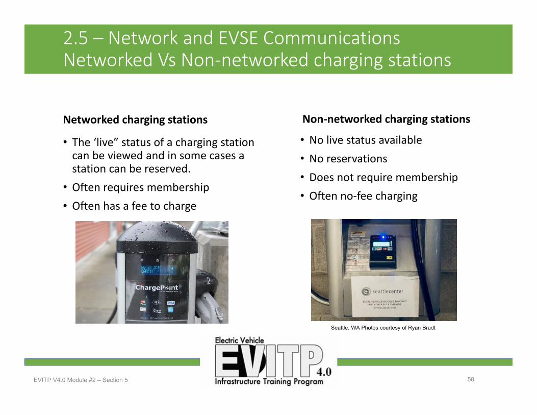
Networked charging stations
• The ‘live” status of a charging station can be viewed and in some cases a station can be reserved.
• Often requires membership• Often has a fee to charge
Non‐networked charging stations
• No live status available • No reservations • Does not require membership• Often no‐fee charging
EVITP V4.0 Module #2 – Section 5 58
Seattle, WA Photos courtesy of Ryan Bradt

2.5 – Network and EVSE CommunicationsNetwork ‐ Blink
EVITP V4.0 Module #2 – Section 5 59
Seattle, WA Photos courtesy of Ryan Bradt
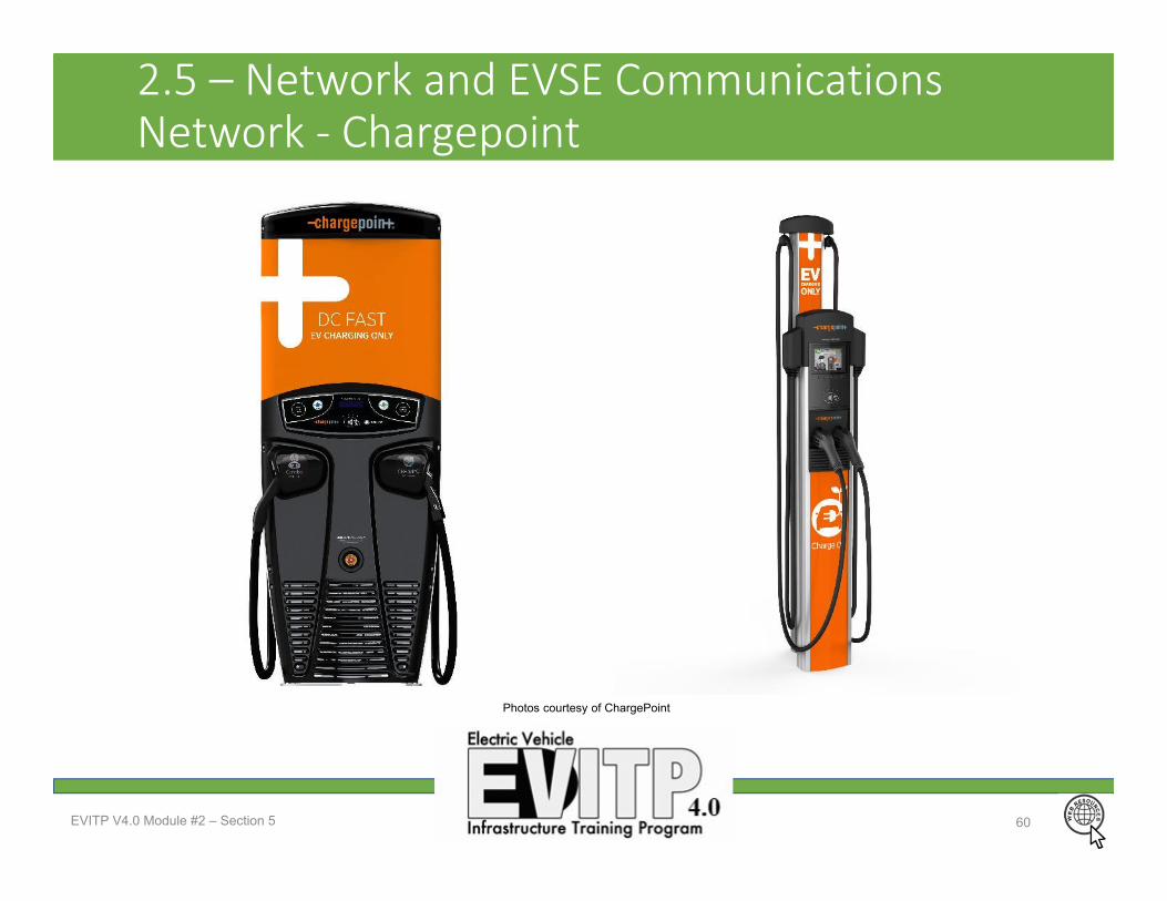
2.5 – Network and EVSE CommunicationsNetwork ‐ Chargepoint
EVITP V4.0 Module #2 – Section 5 60
Photos courtesy of ChargePoint

2.5 – Network and EVSE CommunicationsNetwork ‐ EVgo
EVITP V4.0 Module #2 – Section 5 61
Seattle, WA Photos courtesy of Ryan Bradt

2.5 – Network and EVSE CommunicationsNetwork ‐ SemaConnect
EVITP V4.0 Module #2 – Section 5 62
Photos courtesy of SemaConnect
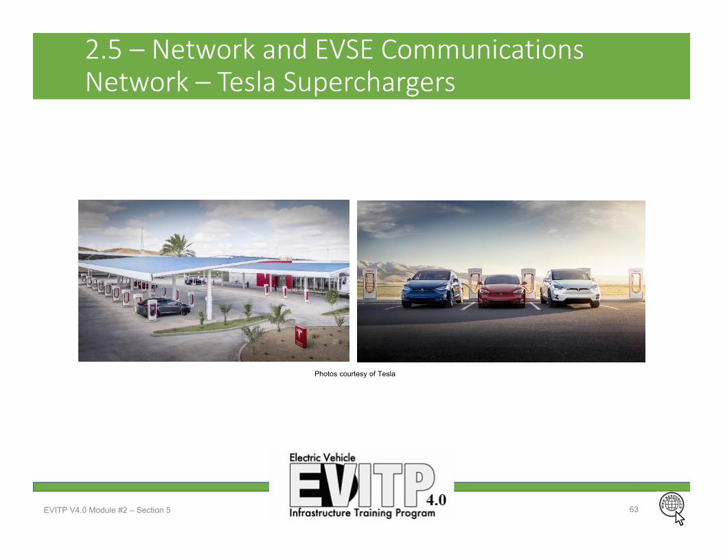
2.5 – Network and EVSE CommunicationsNetwork – Tesla Superchargers
EVITP V4.0 Module #2 – Section 5 63
Photos courtesy of Tesla
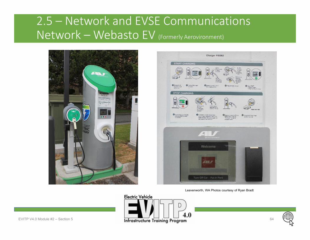
2.5 – Network and EVSE CommunicationsNetwork – Webasto EV (Formerly Aerovironment)
EVITP V4.0 Module #2 – Section 5 64
Leavenworth, WA Photos courtesy of Ryan Bradt
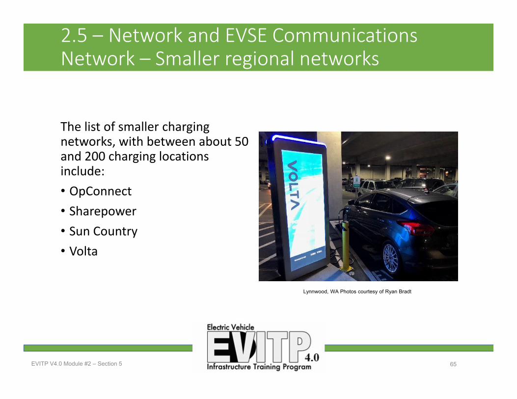
2.5 – Network and EVSE CommunicationsNetwork – Smaller regional networks
The list of smaller charging networks, with between about 50 and 200 charging locations include:• OpConnect• Sharepower• Sun Country• Volta
EVITP V4.0 Module #2 – Section 5 65
Lynnwood, WA Photos courtesy of Ryan Bradt

2.5 – Network and EVSE CommunicationsNetwork – Questions?
EVITP V4.0 Module #2 – Section 5 66
Everett, WA Photos courtesy of Ryan Bradt