Embed Size (px)
Citation preview
ELECTRIC
TRACTION
Learning Objectives
General
Traction System
Direct Steam Engine Drive
Advantages of ElectricTraction
Saving in High Grade Coal
Disadvantages of Electric
Traction
System of Railway Electrifi-
cation
Three Phase Low-Frequency A.C. System
Block Diagram of an ACLocomotive
The Tramways
Collector Gear for OHE
Confusion RegardingWeight and Mass of Train
Tractive Efforts for Propul-sion of a Train
Power Output from DrivingAxles
Energy Output from Driv-ing Axles
Specific Energy Output
Evaluation of Specific
Energy Output Energy Consumption
Specific Energy Consump-tion
Adhesive Weight
Coefficient of Adhesion
CONTENTS
CONTENTS
1700 Electrical Technology
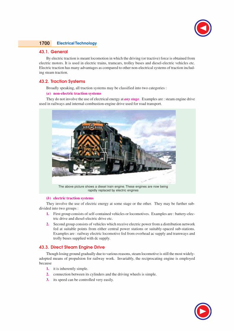
The above picture shows a diesel train engine. These engines are now being
rapidly replaced by electric engines
43.1. General
By electric traction is meant locomotion in which the driving (or tractive) force is obtained from
electric motors. It is used in electric trains, tramcars, trolley buses and diesel-electric vehicles etc.
Electric traction has many advantages as compared to other non-electrical systems of traction includ-
ing steam traction.
43.2. Traction Systems
Broadly speaking, all traction systems may be classified into two categories :
(a) non-electric traction systems
They do not involve the use of electrical energy at any stage. Examples are : steam engine drive
used in railways and internal-combustion-engine drive used for road transport.
(b) electric traction systems
They involve the use of electric energy at some stage or the other. They may be further sub-
divided into two groups :
1. First group consists of self-contained vehicles or locomotives. Examples are : battery-elec-
tric drive and diesel-electric drive etc.
2. Second group consists of vehicles which receive electric power from a distribution network
fed at suitable points from either central power stations or suitably-spaced sub-stations.
Examples are : railway electric locomotive fed from overhead ac supply and tramways and
trolly buses supplied with dc supply.
43.3. Direct Steam Engine Drive
Though losing ground gradually due to various reasons, steam locomotive is still the most widely-
adopted means of propulsion for railway work. Invariably, the reciprocating engine is employed
because
1. it is inherently simple.
2. connection between its cylinders and the driving wheels is simple.
3. its speed can be controlled very easily.
Electric Traction 1701
However, the steam locomotive suffers from the following disadvantages :
1. since it is difficult to install a condenser on a locomotive, the steam engine runs non-con-
densing and, therefore, has a very low thermal efficiency of about 6-8 percent.
2. it has strictly limited overload capacity.
3. it is available for hauling work for about 60% of its working days, the remaining 40% being
spent in preparing for service, in maintenance and overhaul.
43.4. Diesel-electric Drive
It is a self-contained motive power unit which employs a diesel engine for direct drive of a dc
generator. This generator supplies current to traction motors which are geared to the driving axles.
In India, diesel locomotives were introduced in 1945 for shunting service on broad-guage (BG)
sections and in 1956 for high-speed main-line operations on metre-guage (MG) sections. It was only
in 1958 that Indian Railways went in for extensive main-line dieselisation.*
Diesel-electric traction has the following advantages :
1. no modification of existing tracks is required while converting from steam to diesel-electric
traction.
2. it provides greater tractive effort as compared to steam engine which results in higher start-
ing acceleration.
3. it is available for hauling for about 90% of its working days.
4. diesel-electric locomotive is more efficient than a steam locomotive (though less efficient
than an electric locomotive).
Disadvantages
1. for same power, diesel-electric locomotive is costlier than either the steam or electric loco-
motive.
2. overload capacity is limited because diesel engine is a constant-kW output prime mover.
3. life of a diesel engine is comparatively shorter.
4. diesel-electric locomotive is heavier than plain electric locomotive because it carries the
main engine, generator and traction motors etc.
5. regenerative braking cannot be employed though rheostatic braking can be.
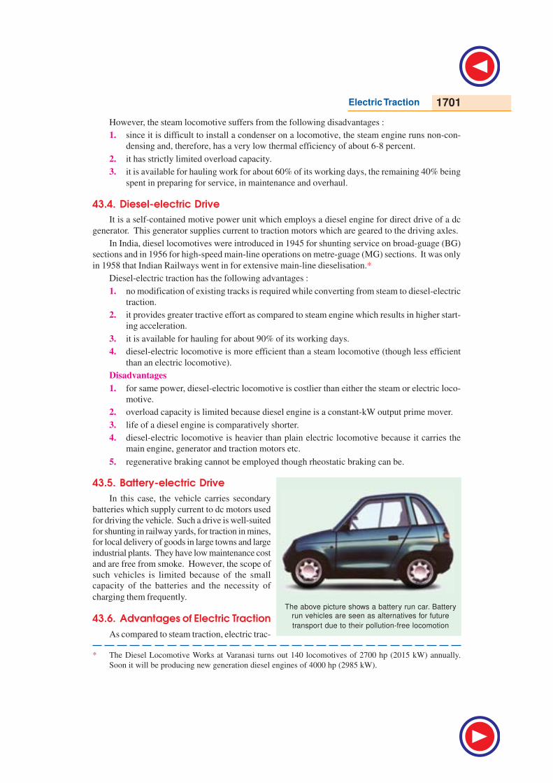
43.5. Battery-electric Drive
In this case, the vehicle carries secondary
batteries which supply current to dc motors used
for driving the vehicle. Such a drive is well-suited
for shunting in railway yards, for traction in mines,
for local delivery of goods in large towns and large
industrial plants. They have low maintenance cost
and are free from smoke. However, the scope of
such vehicles is limited because of the small
capacity of the batteries and the necessity of
charging them frequently.
43.6. Advantages of Electric Traction
As compared to steam traction, electric trac-
The above picture shows a battery run car. Battery
run vehicles are seen as alternatives for future
transport due to their pollution-free locomotion
* The Diesel Locomotive Works at Varanasi turns out 140 locomotives of 2700 hp (2015 kW) annually.
Soon it will be producing new generation diesel engines of 4000 hp (2985 kW).
1702 Electrical Technology
tion has the following advantages :
1. Cleanliness. Since it does not produce any smoke or corrosive fumes, electric traction is
most suited for underground and tube railways. Also, it causes no damage to the buildings and other
apparatus due to the absence of smoke and flue gases.
2. Maintenance Cost. The maintenance cost of an electric locomotive is nearly 50% of that
for a steam locomotive. Moreover, the maintenance time is also much less.
3. Starting Time. An electric locomotive can be started at a moment's notice whereas a steam
locomotive requires about two hours to heat up.
4. High Starting Torque. The motors used in electric traction have a very high starting torque.
Hence, it is possible to achieve higher accelerations of 1.5 to 2.5 km/h/s as against 0.6 to 0.8 km/h/s
in steam traction. As a result, we are able to get the following additional advantages:
(i) high schedule speed
(ii) increased traffic handling capacity
(iii) because of (i) and (ii) above, less terminal space is required—a factor of great importance in
urban areas.
5. Braking. It is possible to use regenerative braking in electric traction system. It leads to the
following advantages :
(i) about 80% of the energy taken from the supply during ascent is returned to it during descent.
(ii) goods traffic on gradients becomes safer and speedier.
(iii) since mechanical brakes are used to a very small extent, maintenance of brake shoes, wheels,
tyres and track rails is considerably reduced because of less wear and tear.
6. Saving in High Grade Coal. Steam locomotives use costly high-grade coal which is not so
abundant. But electric locomotives can be fed either from hydroelectric stations or pit-head thermal
power stations which use cheap low-grade coal. In this way, high-grade coal can be saved for metal-
lurgical purposes.
7. Lower Centre of Gravity. Since height of an electric locomotive is much less than that of
a steam locomotive, its centre of gravity is comparatively low. This fact enables an electric locomo-
tive to negotiate curves at higher speeds quite safely.
8. Absence of Unbalanced Forces. Electric traction has higher coefficient of adhesion since
there are no unbalanced forces produced by reciprocating masses as is the case in steam traction. It
not only reduces the weight/kW ratio of an electric locomotive but also improves its riding quality in
addition to reducing the wear and tear of the track rails.
43.7. Disadvantages of Electric Traction
1. The most vital factor against electric traction is the initial high cost of laying out overhead
electric supply system. Unless the traffic to be handled is heavy, electric traction becomes uneco-
nomical.
2. Power failure for few minutes can cause traffic dislocation for hours.
3. Communication lines which usually run parallel to the power supply lines suffer from elec-
trical interference. Hence, these communication lines have either to be removed away from the rail
track or else underground cables have to be used for the purpose which makes the entire system still
more expensive.
4. Electric traction can be used only on those routes which have been electrified. Obviously,
this restriction does not apply to steam traction.
5. Provision of a negative booster is essential in the case of electric traction. By avoiding the
Electric Traction 1703
flow of return currents through earth, it curtails corrosion of underground pipe work and interference
with telegraph and telephone circuits.
43.8. Systems of Railway Electrification
Presently, following four types of track electrification systems are available :
1. Direct current system—600 V, 750 V, 1500 V, 3000 V
2. Single-phase ac system—15-25 kV, 216
3, 25 and 50 Hz
3. Three-phase ac system—3000-3500 V at 2
163
Hz
4. Composite system—involving conversion of single-phase ac into 3-phase ac or dc.
43.9. Direct Current System
Direct current at 600-750 V is universally employed for tramways in urban areas and for many
suburban railways while 1500-3000 V dc is used for main line railways. The current collection is
from third rail (or conductor rail) up to 750 V, where large currents are involved and from overhead
wire for 1500 V and 3000 V, where small currents are involved. Since in majority of cases, track (or
running) rails are used as the return conductor, only one conductor rail is required. Both of these
contact systems are fed from substations which are spaced 3 to 5 km for heavy suburban traffic and
40-50 km for main lines operating at higher voltages of 1500 V to 3000 V. These sub-stations
themselves receive power from 110/132 kV, 3-phase network (or grid). At these substations, this
high-voltage 3-phase supply is converted into low-voltage 1-phase supply with the help of Scott-
connected or V-connected 3-phase transformers (Art. 31.9). Next, this low ac voltage is converted
into the required dc voltage by using suitable rectifiers or converters (like rotary converter, mercury-
arc, metal or semiconductor rectifiers). These substations are usually automatic and are remote-
controlled.
The dc supply so obtained is fed via suitable contact system to the traction motors which are
either dc series motors for electric locomotive or compound motors for tramway and trolley buses
where regenerative braking is desired.
It may be noted that for heavy suburban service, low voltage dc system is undoubtedly superior
to 1-phase ac system due to the following reasons :
1. dc motors are better suited for frequent and rapid acceleration of heavy trains than ac mo-
tors.
2. dc train equipment is lighter, less costly and more efficient than similar ac equipment.
3. when operating under similar service conditions, dc train consumes less energy than a
1-phase ac train.
4. the conductor rail for dc distribution system is less costly, both initially and in maintenance
than the high-voltage overhead ac distribution system.
5. dc system causes no electrical interference with overhead communication lines.
The only disadvantage of dc system is the necessity of locating ac/dc conversion sub-stations at
relatively short distances apart.
43.10. Single-Phase Low-frequency AC System
In this system, ac voltages from 11 to 15 kV at 23
16 or 25 Hz are used. If supply is from a
generating station exclusively meant for the traction system, there is no difficulty in getting the elec-
tric supply of 23
16 or 25 Hz. If, however, electric supply is taken from the high voltage transmission
lines at 50 Hz, then in addition to step-down transformer, the substation is provided with a frequency
1704 Electrical Technology
converter. The frequency converter equipment consists of a 3-phase synchronous motor which drives
a I-phase alternator having or 25 Hz frequency.
The 15 kV 23
16 or 25 Hz supply is fed to the electric locomotor via a single over-head wire
(running rail providing the return path).
A step-down transformer carried by the locomotive reduces the 15-kV voltage to 300-400 V for
feeding the ac series motors. Speed regulation of ac series motors is achieved by applying variable
voltage from the tapped secondary of the above transformer.
Low-frequency ac supply is used because apart from improving the commutation properties of
ac motors, it increases their efficiency and power factor. Moreover, at low frequency, line reactance
is less so that line impedance drop and hence line voltage drop is reduced. Because of this reduced
line drop, it is feasible to space the substations 50 to 80 km apart. Another advantage of employing
low frequency is that it reduces telephonic interference.
41.11. Three-phase Low-frequency AC System
It uses 3-phase induction motors which work on a 3.3 kV, 23
16 Hz supply. Sub-stations receive
power at a very high voltage from 3-phase transmission lines at the usual industrial frequency of
50 Hz. This high voltage is stepped down to 3.3 kV by transformers whereas frequency is reduced
from 50 Hz to 23
16 Hz by frequency converters installed at the sub-stations. Obviously, this system
employs two overhead contact wires, the track rail forming the third phase (of course, this leads to
insulation difficulties at the junctions).
Induction motors used in the system are quite simple and robust and give trouble-free operation.
They possess the merits of high efficiency and of operating as a generator when driven at speeds
above the synchronous speed. Hence, they have the property of automatic regenerative braking
during the descent on gradients. However, it may be noted that despite all its advantages, this system
has not found much favour and has, in fact, become obsolete because of its certain inherent limita-
tions given below :
1. the overhead contact wire system becomes complicated at crossings and junctions.
2. constant-speed characteristics of induction motors are not suitable for traction work.
3. induction motors have speed/torque characteristics similar to dc shunt motors. Hence, they
are not suitable for parallel operation because, even with little difference in rotational speeds
caused by unequal diameters of the wheels, motors will becomes loaded very unevenly.
43.12. Composite System
Such a system incorporates good points of two systems while ignoring their bad points. Two such
composite systems presently in use are :
1. 1-phase to 3-phase system also called Kando system
2. 1-phase to dc system.
43.13. Kando System
In this system, single-phase 16-kV, 50 Hz supply from the sub-station is picked up by the loco-
motive through the single overhead contact wire. It is then converted into 3-phase ac supply at the
same frequency by means of phase converter equipment carried on the locomotives. This 3-phase
supply is then fed to the 3-phase induction motors.
Electric Traction 1705
As seen, the complicated overhead two contact wire arrangement of ordinary 3-phase system is
replaced by a single wire system. By using silicon controlled rectifier as inverter, it is possible to get
variable-frequency 3-phase supply at 1/2 to 9 Hz frequency. At this low frequency, 3-phase motors
develop high starting torque without taking excessive current. In view of the above, Kando system is
likely to be developed further.
43.14. Single-phase AC to DC System
This system combines the advantages of high-voltage ac distribution at industrial frequency with
the dc series motors traction. It employs overhead 25-kV, 50-Hz supply which is stepped down by the
transformer installed in the locomotive itself. The low-voltage ac supply is then converted into dc
supply by the rectifier which is also carried on the locomotive. This dc supply is finally fed to dc
series traction motor fitted between the wheels. The system of traction employing 25-kV, 50-Hz,
1-phase ac supply has been adopted for all future track electrification in India.
43.15. Advantages of 25-kV, 50-Hz AC System
Advantages of this system of track electrification over other systems particularly the dc system
are as under :
1. Light Overhead Catenary
Since voltage is high (25 kV), line current for a given traction demand is less. Hence, cross-
section of the overhead conductors is reduced. Since these small-sized conductors are light, support-
ing structures and foundations are also light and simple. Of course, high voltage needs higher insula-
tion which increases the cost of overhead equipment (OHE) but the reduction in the size of conduc-
tors has an overriding effect.
2. Less Number of Substations
Since in the 25-kV system, line current is less, line voltage drop which is mainly due to the
resistance of the line is correspondingly less. It improves the voltage regulation of the line which fact
makes larger spacing of 50-80 km between sub-stations possible as against 5-15 km with 1500 V dc
system and 15-30 km with 3000 V dc sysem. Since the required number of substations along the track
is considerably reduced, it leads to substantial saving in the capital expenditure on track electrifica-
tion.
3. Flexibility in the Location of Substations
Larger spacing of substations leads to greater flexibility in the selection of site for their proper
location. These substations can be located near the national high-voltage grid which, in our country,
fortunately runs close to the main railway routes. The substations are fed from this grid thereby
saving the railway administration lot of expenditure for erecting special transmission lines for their
substations. On the other hand, in view of closer spacing of dc substations and their far away location,
railway administration has to erect its own transmission lines for taking feed from the national grid to
the substations which consequently increases the initial cost of electrification.
4. Simplicity of Substation Design
In ac systems, the substations are simple in design and layout because they do not have to install
and maintain rotary converters or rectifiers as in dc systems. They only consist of static transformers
alongwith their associated switchgear and take their power directly from the high-voltage national
grid running over the length and breadth of our country. Since such sub-stations are remotely con-
trolled, they have few attending personnel or even may be unattended.
1706 Electrical Technology
5. Lower Cost of Fixed Installations
The cost of fixed installations is much less for 25 kV ac system as compared to dc system. In fact,
cost is in ascending order for 25 kV ac, 3000 V dc and 1500 V dc systems. Consequently, traffic
densities for which these systems are economical are also in the ascending order.
6. Higher Coefficient of Adhesion
The straight dc locomotive has a coefficient of adhesion of about 27% whereas its value for ac
rectifier locomotive is nearly 45%. For this reason, a lighter ac locomotive can haul the same load as
a heavier straight dc locomotive. Consequently, ac locomotives are capable of achieving higher
speeds in coping with heavier traffic.
7. Higher Starting Efficiency
An ac locomotive has higher starting efficiency than a straight dc locomotive. In dc locomotive
supply voltage at starting is reduced by means of ohmic resistors but by on-load primary or secondary
tap-changer in ac locomotives.
43.16. Disadvantages of 25-kV AC System
1. Single-phase ac system produces both current and voltage unbalancing effect on the supply.
2. It produces interference in telecommunication circuits. Fortunately, it is possible at least to
minimize both these undesirable effects.
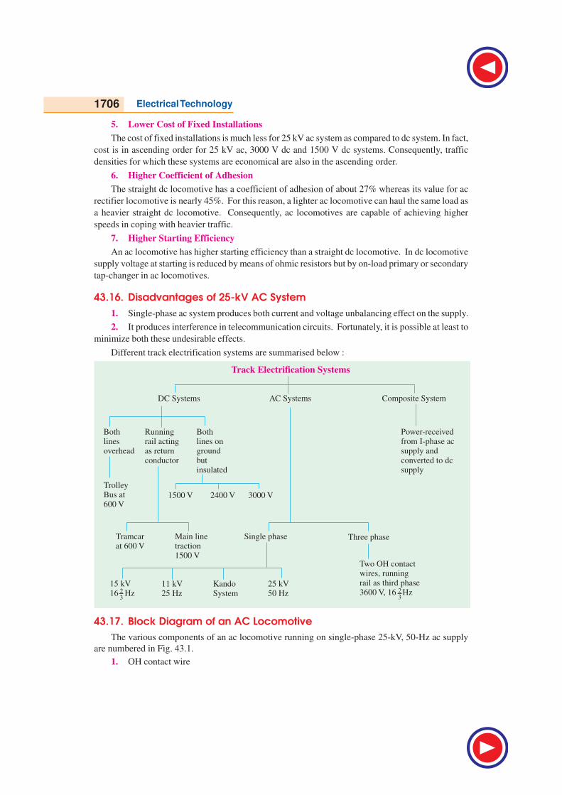
Different track electrification systems are summarised below :
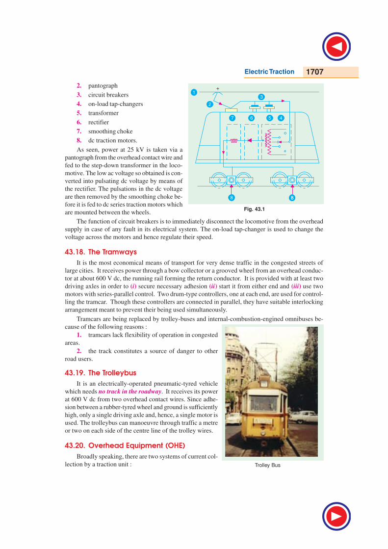
43.17. Block Diagram of an AC Locomotive
The various components of an ac locomotive running on single-phase 25-kV, 50-Hz ac supply
are numbered in Fig. 43.1.
1. OH contact wire
Electric Traction 1707
Fig. 43.1
2. pantograph
3. circuit breakers
4. on-load tap-changers
5. transformer
6. rectifier
7. smoothing choke
8. dc traction motors.
As seen, power at 25 kV is taken via a
pantograph from the overhead contact wire and
fed to the step-down transformer in the loco-
motive. The low ac voltage so obtained is con-
verted into pulsating dc voltage by means of
the rectifier. The pulsations in the dc voltage
are then removed by the smoothing choke be-
fore it is fed to dc series traction motors which
are mounted between the wheels.
The function of circuit breakers is to immediately disconnect the locomotive from the overhead
supply in case of any fault in its electrical system. The on-load tap-changer is used to change the
voltage across the motors and hence regulate their speed.
43.18. The Tramways
It is the most economical means of transport for very dense traffic in the congested streets of
large cities. It receives power through a bow collector or a grooved wheel from an overhead conduc-
tor at about 600 V dc, the running rail forming the return conductor. It is provided with at least two
driving axles in order to (i) secure necessary adhesion (ii) start it from either end and (iii) use two
motors with series-parallel control. Two drum-type controllers, one at each end, are used for control-
ling the tramcar. Though these controllers are connected in parallel, they have suitable interlocking
arrangement meant to prevent their being used simultaneously.
Tramcars are being replaced by trolley-buses and internal-combustion-engined omnibuses be-
cause of the following reasons :
1. tramcars lack flexibility of operation in congested
areas.
2. the track constitutes a source of danger to other
road users.
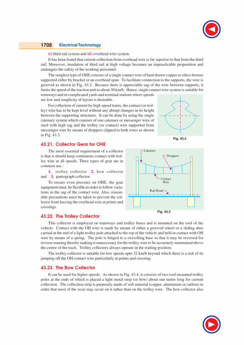
43.19. The Trolleybus
It is an electrically-operated pneumatic-tyred vehicle
which needs no track in the roadway. It receives its power
at 600 V dc from two overhead contact wires. Since adhe-
sion between a rubber-tyred wheel and ground is sufficiently
high, only a single driving axle and, hence, a single motor is
used. The trolleybus can manoeuvre through traffic a metre
or two on each side of the centre line of the trolley wires.
43.20. Overhead Equipment (OHE)
Broadly speaking, there are two systems of current col-
lection by a traction unit : Trolley Bus
1708 Electrical Technology
(i) third rail system and (ii) overhead wire system.
It has been found that current collection from overhead wire is far superior to that from the third
rail. Moreover, insulation of third rail at high voltage becomes an impracticable proposition and
endangers the safety of the working personnel.
The simplest type of OHE consists of a single contact wire of hard drawn copper or silico-bronze
supported either by bracket or an overhead span. To facilitate connection to the supports, the wire is
grooved as shown in Fig. 43.2. Because there is appreciable sag of the wire between supports, it
limits the speed of the traction unit to about 30 km/h. Hence, single contact wire system is suitable for
tramways and in complicated yards and terminal stations where speeds
are low and simplicity of layout is desirable.
For collection of current by high-speed trains, the contact (or trol-
ley) wire has to be kept level without any abrupt changes in its height
between the supporting structures. It can be done by using the single
catenary system which consists of one catenary or messenger wire of
steel with high sag and the trolley (or contact) wire supported from
messenger wire by means of droppers clipped to both wires as shown
in Fig. 43.3.
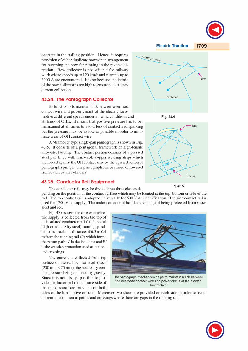
43.21. Collector Gear for OHE
The most essential requirement of a collector
is that it should keep continuous contact with trol-
ley wire at all speeds. Three types of gear are in
common use :
1. trolley collector 2. bow collector
and 3. pantograph collector.
To ensure even pressure on OHE, the gear
equipment must, be flexible in order to follow varia-
tions in the sag of the contact wire. Also, reason-
able precautions must be taken to prevent the col-
lector from leaving the overhead wire at points and
crossings.
43.22. The Trolley Collector
This collector is employed on tramways and trolley buses and is mounted on the roof of the
vehicle. Contact with the OH wire is made by means of either a grooved wheel or a sliding shoe
carried at the end of a light trolley pole attached to the top of the vehicle and held in contact with OH
wire by means of a spring. The pole is hinged to a swivelling base so that it may be reversed for
reverse running thereby making it unnecessary for the trolley wire to be accurately maintained above
the centre of the track. Trolley collectors always operate in the trailing position.
The trolley collector is suitable for low speeds upto 32 km/h beyond which there is a risk of its
jumping off the OH contact wire particularly at points and crossing.
43.23. The Bow Collector
It can be used for higher speeds. As shown in Fig. 43.4, it consists of two roof-mounted trolley
poles at the ends of which is placed a light metal strip (or bow) about one metre long for current
collection. The collection strip is purposely made of soft material (copper, aluminium or carbon) in
order that most of the wear may occur on it rather than on the trolley wire. The bow collector also
Fig. 43.2
Fig. 43.3
Electric Traction 1709
operates in the trailing position. Hence, it requires
provision of either duplicate bows or an arrangement
for reversing the bow for running in the reverse di-
rection. Bow collector is not suitable for railway
work where speeds up to 120 km/h and currents up to
3000 A are encountered. It is so because the inertia
of the bow collector is too high to ensure satisfactory
current collection.
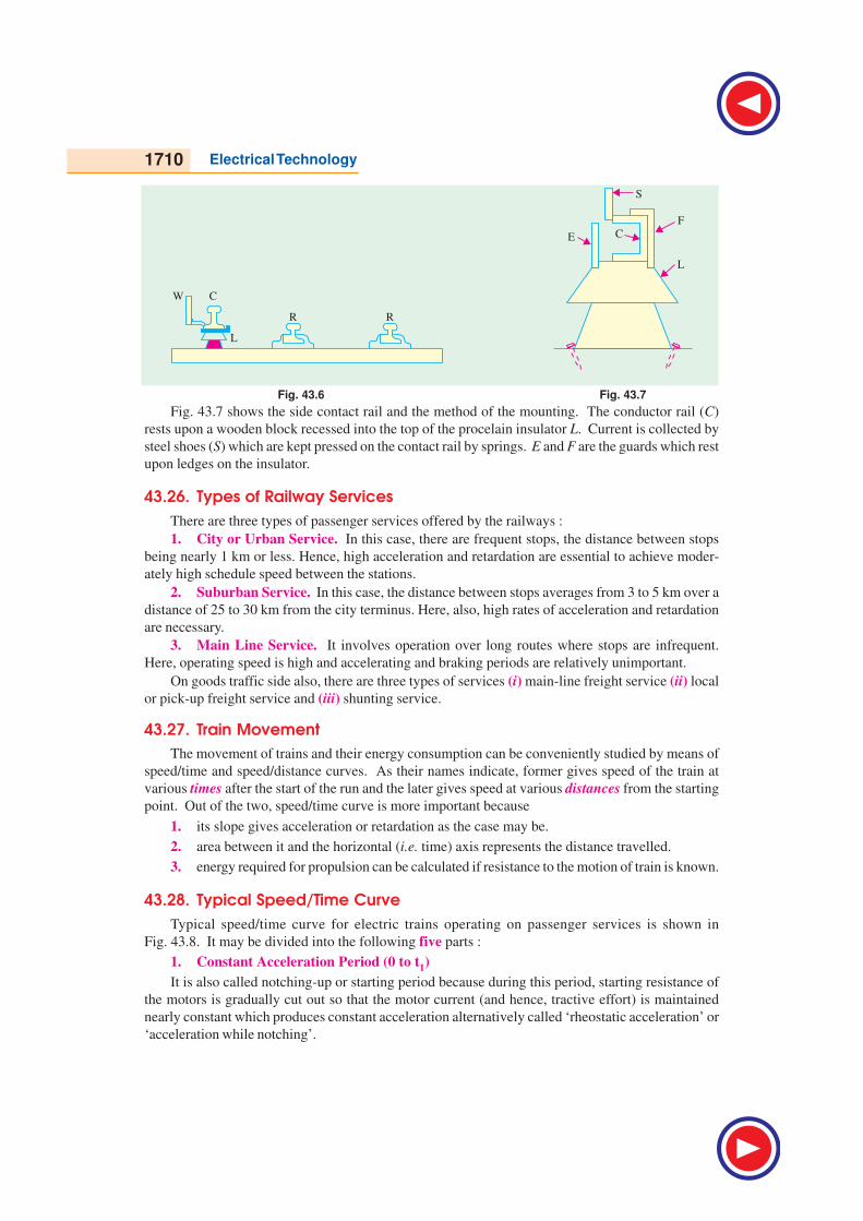
43.24. The Pantograph Collector
Its function is to maintain link between overhead
contact wire and power circuit of the electric loco-
motive at different speeds under all wind conditions and
stiffness of OHE. It means that positive pressure has to be
maintained at all times to avoid loss of contact and sparking
but the pressure must be as low as possible in order to mini-
mize wear of OH contact wire.
A ‘diamond’ type single-pan pantograph is shown in Fig.
43.5. It consists of a pentagonal framework of high-tensile
alloy-steel tubing. The contact portion consists of a pressed
steel pan fitted with renewable copper wearing strips which
are forced against the OH contact wire by the upward action of
pantograph springs. The pantograph can be raised or lowered
from cabin by air cylinders.
43.25. Conductor Rail Equipment
The conductor rails may be divided into three classes de-
pending on the position of the contact surface which may be located at the top, bottom or side of therail. The top contact rail is adopted universally for 600 V dc electrification. The side contact rail isused for 1200 V dc supply. The under contact rail has the advantage of being protected from snow,sleet and ice.
Fig. 43.6 shows the case when elec-tric supply is collected from the top ofan insulated conductor rail C (of special
high-conductivity steel) running paral-
lel to the track at a distance of 0.3 to 0.4
m from the running rail (R) which forms
the return path. L is the insulator and W
is the wooden protection used at stations
and crossings.
The current is collected from top
surface of the rail by flat steel shoes
(200 mm × 75 mm), the necessary con-
tact pressure being obtained by gravity.
Since it is not always possible to pro-
vide conductor rail on the same side of
the track, shoes are provided on both
sides of the locomotive or train. Moreover two shoes are provided on each side in order to avoid
current interruption at points and crossings where there are gaps in the running rail.
The pantograph mechanism helps to maintain a link between
the overhead contact wire and power circuit of the electric
locomotive
Fig. 43.5
Fig. 43.4
1710 Electrical Technology
Fig. 43.6 Fig. 43.7
Fig. 43.7 shows the side contact rail and the method of the mounting. The conductor rail (C)
rests upon a wooden block recessed into the top of the procelain insulator L. Current is collected by
steel shoes (S) which are kept pressed on the contact rail by springs. E and F are the guards which rest
upon ledges on the insulator.
43.26. Types of Railway Services
There are three types of passenger services offered by the railways :
1. City or Urban Service. In this case, there are frequent stops, the distance between stops
being nearly 1 km or less. Hence, high acceleration and retardation are essential to achieve moder-
ately high schedule speed between the stations.
2. Suburban Service. In this case, the distance between stops averages from 3 to 5 km over a
distance of 25 to 30 km from the city terminus. Here, also, high rates of acceleration and retardation
are necessary.
3. Main Line Service. It involves operation over long routes where stops are infrequent.
Here, operating speed is high and accelerating and braking periods are relatively unimportant.
On goods traffic side also, there are three types of services (i) main-line freight service (ii) local
or pick-up freight service and (iii) shunting service.
43.27. Train Movement
The movement of trains and their energy consumption can be conveniently studied by means of
speed/time and speed/distance curves. As their names indicate, former gives speed of the train at
various times after the start of the run and the later gives speed at various distances from the starting
point. Out of the two, speed/time curve is more important because
1. its slope gives acceleration or retardation as the case may be.
2. area between it and the horizontal (i.e. time) axis represents the distance travelled.
3. energy required for propulsion can be calculated if resistance to the motion of train is known.
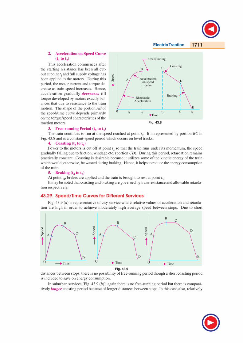
43.28. Typical Speed/Time Curve
Typical speed/time curve for electric trains operating on passenger services is shown in
Fig. 43.8. It may be divided into the following five parts :
1. Constant Acceleration Period (0 to t1)
It is also called notching-up or starting period because during this period, starting resistance of
the motors is gradually cut out so that the motor current (and hence, tractive effort) is maintained
nearly constant which produces constant acceleration alternatively called ‘rheostatic acceleration’ or
‘acceleration while notching’.
Electric Traction 1711
2. Acceleration on Speed Curve
(t1 to t2)
This acceleration commences after
the starting resistance has been all cut-
out at point t1 and full supply voltage has
been applied to the motors. During this
period, the motor current and torque de-
crease as train speed increases. Hence,
acceleration gradually decreases till
torque developed by motors exactly bal-
ances that due to resistance to the train
motion. The shape of the portion AB of
the speed/time curve depends primarily
on the torque/speed characteristics of the
traction motors.
3. Free-running Period (t2 to t3)
The train continues to run at the speed reached at point t2. It is represented by portion BC in
Fig. 43.8 and is a constant-speed period which occurs on level tracks.
4. Coasting (t3 to t4)
Power to the motors is cut off at point t3 so that the train runs under its momentum, the speed
gradually falling due to friction, windage etc. (portion CD). During this period, retardation remains
practically constant. Coasting is desirable because it utilizes some of the kinetic energy of the train
which would, otherwise, be wasted during braking. Hence, it helps to reduce the energy consumption
of the train.
5. Braking (t4 to t5)
At point t4, brakes are applied and the train is brought to rest at point t5.
It may be noted that coasting and braking are governed by train resistance and allowable retarda-
tion respectively.
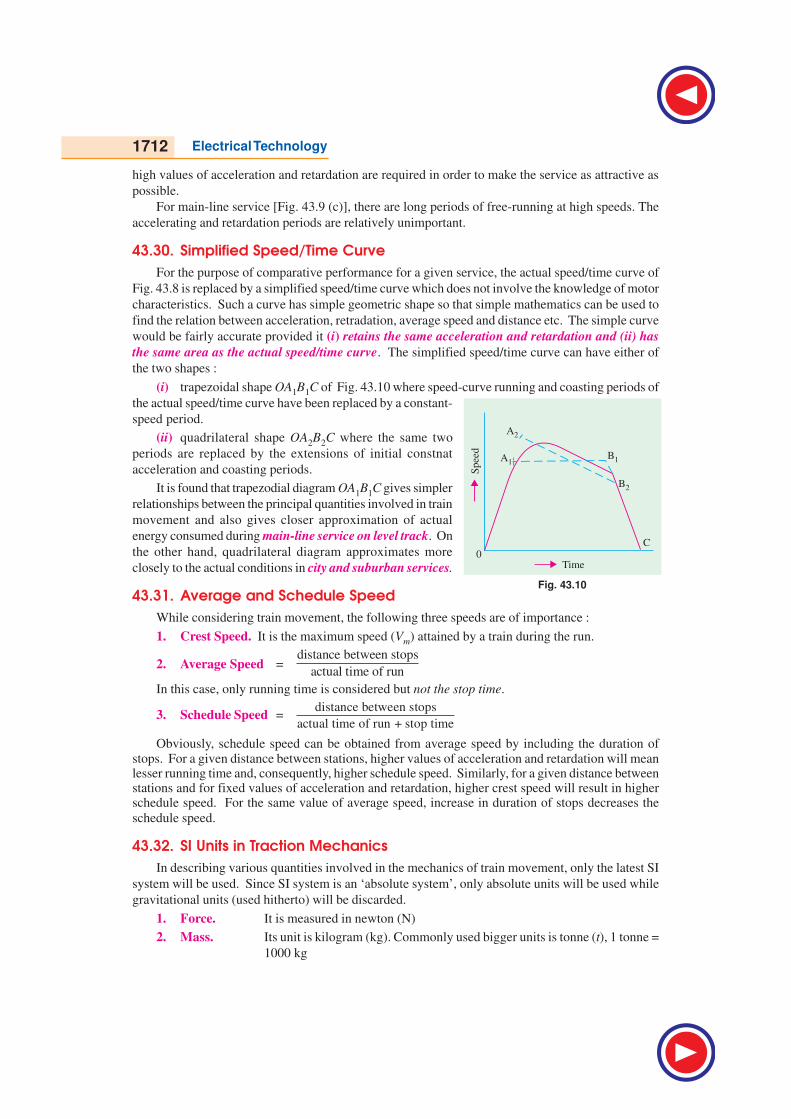
43.29. Speed/Time Curves for Different Services
Fig. 43.9 (a) is representative of city service where relative values of acceleration and retarda-
tion are high in order to achieve moderately high average speed between stops. Due to short
Fig. 43.9
distances between stops, there is no possibility of free-running period though a short coasting period
is included to save on energy consumption.
In suburban services [Fig. 43.9 (b)], again there is no free-running period but there is compara-
tively longer coasting period because of longer distances between stops. In this case also, relatively
Fig. 43.8
1712 Electrical Technology
high values of acceleration and retardation are required in order to make the service as attractive as
possible.
For main-line service [Fig. 43.9 (c)], there are long periods of free-running at high speeds. The
accelerating and retardation periods are relatively unimportant.
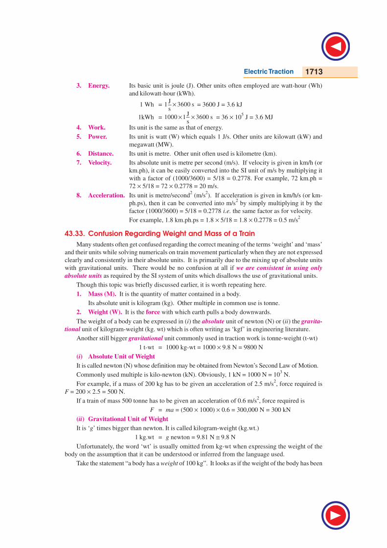
43.30. Simplified Speed/Time Curve
For the purpose of comparative performance for a given service, the actual speed/time curve of
Fig. 43.8 is replaced by a simplified speed/time curve which does not involve the knowledge of motor
characteristics. Such a curve has simple geometric shape so that simple mathematics can be used to
find the relation between acceleration, retradation, average speed and distance etc. The simple curve
would be fairly accurate provided it (i) retains the same acceleration and retardation and (ii) has
the same area as the actual speed/time curve. The simplified speed/time curve can have either of
the two shapes :
(i) trapezoidal shape OA1B1C of Fig. 43.10 where speed-curve running and coasting periods of
the actual speed/time curve have been replaced by a constant-
speed period.
(ii) quadrilateral shape OA2B2C where the same two
periods are replaced by the extensions of initial constnat
acceleration and coasting periods.
It is found that trapezodial diagram OA1B1C gives simpler
relationships between the principal quantities involved in train
movement and also gives closer approximation of actual
energy consumed during main-line service on level track. On
the other hand, quadrilateral diagram approximates more
closely to the actual conditions in city and suburban services.
43.31. Average and Schedule Speed
While considering train movement, the following three speeds are of importance :
1. Crest Speed. It is the maximum speed (Vm) attained by a train during the run.
2. Average Speed =distance between stops
actual time of run
In this case, only running time is considered but not the stop time.
3. Schedule Speed =distance between stops
actual time of run + stop time
Obviously, schedule speed can be obtained from average speed by including the duration ofstops. For a given distance between stations, higher values of acceleration and retardation will meanlesser running time and, consequently, higher schedule speed. Similarly, for a given distance betweenstations and for fixed values of acceleration and retardation, higher crest speed will result in higherschedule speed. For the same value of average speed, increase in duration of stops decreases the
schedule speed.
43.32. SI Units in Traction Mechanics
In describing various quantities involved in the mechanics of train movement, only the latest SI
system will be used. Since SI system is an ‘absolute system’, only absolute units will be used while
gravitational units (used hitherto) will be discarded.
1. Force. It is measured in newton (N)
2. Mass. Its unit is kilogram (kg). Commonly used bigger units is tonne (t), 1 tonne =
1000 kg
Spee
d
Time
A1B1
B2
A2
0C
Fig. 43.10
Electric Traction 1713
3. Energy. Its basic unit is joule (J). Other units often employed are watt-hour (Wh)
and kilowatt-hour (kWh).
1 Wh = J
1 3600 ss
× = 3600 J = 3.6 kJ
1kWh = J
1000 1 3600 ss
× × = 36 × 105 J = 3.6 MJ
4. Work. Its unit is the same as that of energy.
5. Power. Its unit is watt (W) which equals 1 J/s. Other units are kilowatt (kW) and
megawatt (MW).
6. Distance. Its unit is metre. Other unit often used is kilometre (km).
7. Velocity. Its absolute unit is metre per second (m/s). If velocity is given in km/h (or
km.ph), it can be easily converted into the SI unit of m/s by multiplying it
with a factor of (1000/3600) = 5/18 = 0.2778. For example, 72 km.ph =
72 × 5/18 = 72 × 0.2778 = 20 m/s.
8. Acceleration. Its unit is metre/second2 (m/s
2). If acceleration is given in km/h/s (or km-
ph.ps), then it can be converted into m/s2 by simply multiplying it by the
factor (1000/3600) = 5/18 = 0.2778 i.e. the same factor as for velocity.
For example, 1.8 km.ph.ps = 1.8 × 5/18 = 1.8 × 0.2778 = 0.5 m/s2
43.33. Confusion Regarding Weight and Mass of a Train
Many students often get confused regarding the correct meaning of the terms ‘weight’ and ‘mass’
and their units while solving numericals on train movement particularly when they are not expressed
clearly and consistently in their absolute units. It is primarily due to the mixing up of absolute units
with gravitational units. There would be no confusion at all if we are consistent in using only
absolute units as required by the SI system of units which disallows the use of gravitational units.
Though this topic was briefly discussed earlier, it is worth repeating here.
1. Mass (M). It is the quantity of matter contained in a body.
Its absolute unit is kilogram (kg). Other multiple in common use is tonne.
2. Weight (W). It is the force with which earth pulls a body downwards.
The weight of a body can be expressed in (i) the absolute unit of newton (N) or (ii) the gravita-
tional unit of kilogram-weight (kg. wt) which is often writing as ‘kgf’ in engineering literature.
Another still bigger gravitational unit commonly used in traction work is tonne-weight (t-wt)
1 t-wt = 1000 kg-wt = 1000 × 9.8 N = 9800 N
(i) Absolute Unit of Weight
It is called newton (N) whose definition may be obtained from Newton’s Second Law of Motion.
Commonly used multiple is kilo-newton (kN). Obviously, 1 kN = 1000 N = 103 N.
For example, if a mass of 200 kg has to be given an acceleration of 2.5 m/s2, force required is
F = 200 × 2.5 = 500 N.
If a train of mass 500 tonne has to be given an acceleration of 0.6 m/s2, force required is
F = ma = (500 × 1000) × 0.6 = 300,000 N = 300 kN
(ii) Gravitational Unit of Weight
It is ‘g’ times bigger than newton. It is called kilogram-weight (kg.wt.)
1 kg.wt = g newton = 9.81 N ≅ 9.8 N
Unfortunately, the word ‘wt’ is usually omitted from kg-wt when expressing the weight of the
body on the assumption that it can be understood or inferred from the language used.
Take the statement “a body has a weight of 100 kg”. It looks as if the weight of the body has been
1714 Electrical Technology
expressed in terms of the mass unit ‘kg’. To avoid this confusion, statement should be ‘a body has a
weight of 100 kg. wt.’ But the first statement is justified by the writers on the ground that since the
word ‘weight’ has already been used in the statement, it should be automatically understood by the
readers that ‘kg’ is not the ‘kg’ of mass but is kg-wt. It would be mass kg if the statement is ‘a body
has a mass of 100 kg’. Often kg-wt is written as ‘kgf’ where ‘f’ is the first letter of the word force and
is added to distinguish it from kg of mass.
Now, consider the statement “a body weighing 500 kg travels with a speed of 36 km/h..........”
Now, weight of the body W = 500 kg.wt. = 500 × 9.8 N
Since we know the weight of the body, we can find its mass from the relation W = mg. But while
using this equation, it is essential that we must consistently use the absolute units only. In this
equation, W must be in newton (not in kg. wt), m in kg and g in m/s2.
∴ 500 × 9.8 = m × 9.8 ; ∴ m = 500 kg
It means that a body which weighs 500 kg (wt) has a mass of 500 kg.
As a practical rule, weight of a body in gravitational units is numerically equal to its mass in
absolute units. This simple fact must be clearly understood to avoid any confusion between weight
and mass of a body.
A train which weighs 500 tonne has a mass of 500 tonne as proved below :
train weight, W = 500 tonne-wt = 500 × 1000 kg-wt = 500 × 1000 × 9.8 N
Now, W = mg ; ∴ 500 × 1000 × 9.8 = m × 9.8
∴ m = 500 × 1000 kg = 500 × 1000/1000 = 500 tonne
To avoid this unfortunate confusion, it would be helpful to change our terminology. For example,
instead of saying “a train weighing 500 tonne is........” it is better to say “a 500-t train is .........” or “a
train having a mass of 500 t is .............”
In order to remove this confusion, SI system of units has disallowed the use of gravitational units.
There will be no confusion if we consistently use only absolute units.
43.34. Quantities Involved in Traction Mechanics
Following principal quantities are involved in train movement :
D = distance between stops M = dead mass of the train
Me = effective mass of the train W = dead weight of the train
We = effective weight of the train α = accelaration during starting period
βc = retardation during coasting β = retardation during braking
Va = average speed Vm = maximum (or crest) speed.
t = total time for the run t1 = time of acceleration
t2 = time of free running = t − (t1 + t3) t3 = time of braking
Ft = tractive effort T = torque
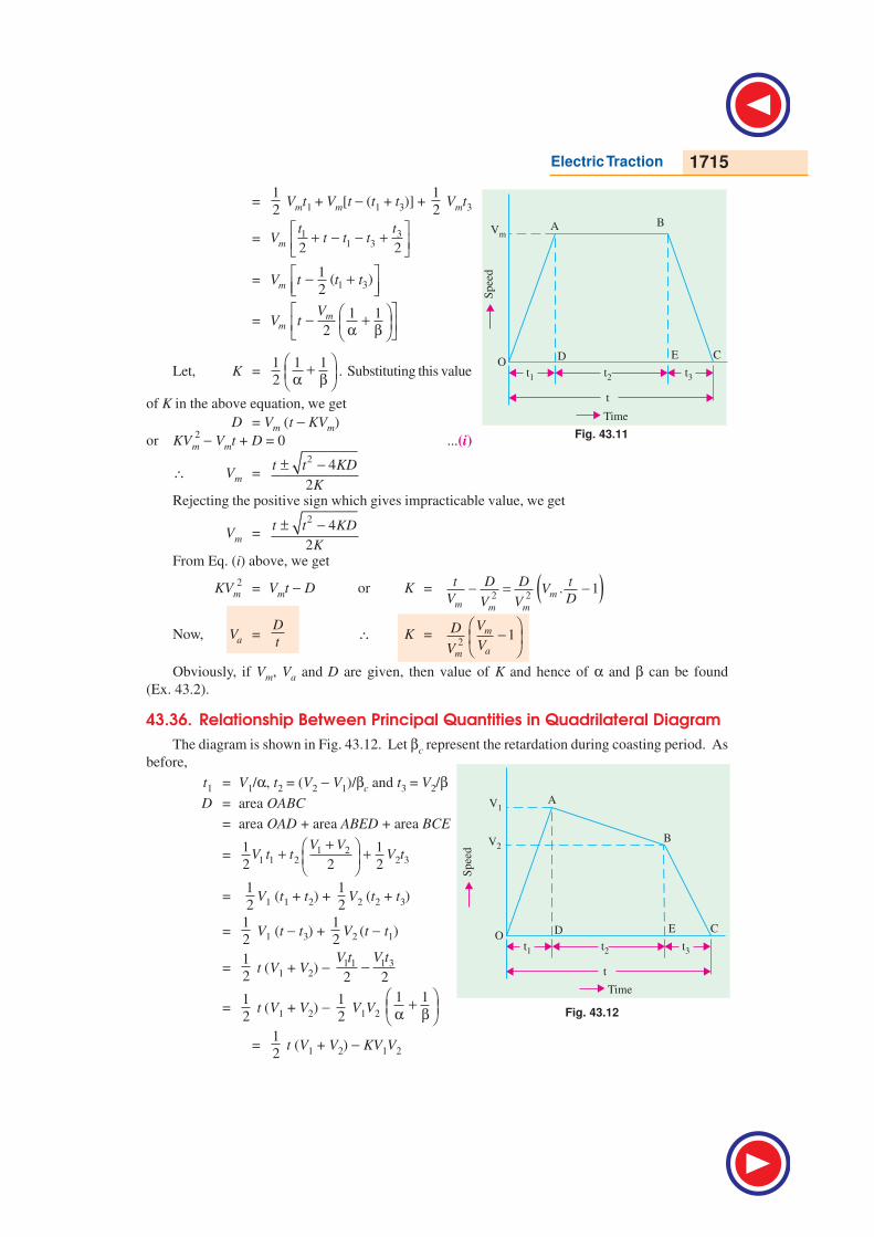
43.35. Relationship Between Principal Quantities in Trapezoidal Diagram
As seen from Fig. 43.11.
α = Vm /t1 or t1 = Vm /αβ = Vm /t3 or t3 = Vm /β
As we know, total distance D between the two stops is given by the area of trapezium OABC.
∴ D = area OABC
= area OAD + area ABED + area BCE
=1
2 Vmt1 + Vmt2 +
1
2 Vmt3
Electric Traction 1715
=1
2 Vmt1 + Vm[t − (t1 + t3)] +
1
2 Vmt3
= 311 32 2m
ttV t t t
+ − − +
= 1 31
( )2mV t t t − +
=1 1
2m
m
VV t
− + α β
Let, K =1 1 1
2
+ α β . Substituting this value
of K in the above equation, we get
D = Vm (t − KVm)
or KVm
2 − Vmt + D = 0 ...(i)
∴ Vm =2
4
2
t t KD
K
± −
Rejecting the positive sign which gives impracticable value, we get
Vm =2
4
2
t t KD
K
± −
From Eq. (i) above, we get
KVm
2= Vmt − D or K = ( )2 2
. 1mm m m
t D D tV
V DV V− = −
Now, Va =D
t∴ K =
21m
am
VD
VV
−
Obviously, if Vm, Va and D are given, then value of K and hence of α and β can be found
(Ex. 43.2).
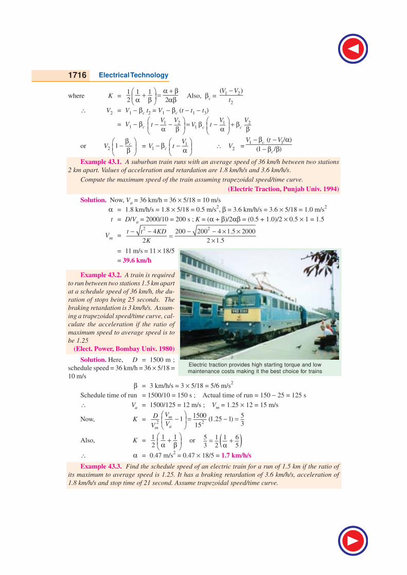
43.36. Relationship Between Principal Quantities in Quadrilateral Diagram
The diagram is shown in Fig. 43.12. Let βc represent the retardation during coasting period. As
before,
t1 = V1/α, t2 = (V2 − V1)/βc and t3 = V2/βD = area OABC
= area OAD + area ABED + area BCE
= 1 21 1 2 2 3
1 1
2 2 2
V VV t t V t
+ + +
= 1
2V1 (t1 + t2) +
1
2V2 (t2 + t3)
=1
2 V1 (t − t3) +
1
2V2 (t − t1)
=1
2 t (V1 + V2) − 1 31 1
2 2
V tV t−
=1
2 t (V1 + V2) −
1
2 V1V2
1 1 + α β
=1
2 t (V1 + V2) − KV1V2
Spee
d
t1
Vm
t3t2
Time
t
A B
CEDO
Fig. 43.11
Spee
d
t1
V1
V2
t3t2
Time
t
A
B
CEDO
Fig. 43.12
1716 Electrical Technology
where K =1 1 1
2 2
α + β + = α β αβ Also, βc =
1 2
2
( )V V
t
−
∴ V2 = V1 − βc t2 = V1 − βc (t − t1 − t3)
= V1 − βc 1 2 1 2
1 c c
V V V Vt V t
− − = β − + β α β α β
or 2 1 cVβ − β
= 11 c
VV t
− β − α ∴ V2 =
1 1( / )
(1 / )c
c
V t V− β − α− β β
Example 43.1. A suburban train runs with an average speed of 36 km/h between two stations
2 km apart. Values of acceleration and retardation are 1.8 km/h/s and 3.6 km/h/s.
Compute the maximum speed of the train assuming trapezoidal speed/time curve.
(Electric Traction, Punjab Univ. 1994)
Solution. Now, Va = 36 km/h = 36 × 5/18 = 10 m/s
α = 1.8 km/h/s = 1.8 × 5/18 = 0.5 m/s2, β = 3.6 km/h/s = 3.6 × 5/18 = 1.0 m/s
2
t = D/Va = 2000/10 = 200 s ; K = (α + β)/2αβ = (0.5 + 1.0)/2 × 0.5 × 1 = 1.5
Vm =2 2
4 200 200 4 1.5 2000
2 2 1.5
t t KD
K
− − − − × ×=
×
= 11 m/s = 11 × 18/5
= 39.6 km/h
Example 43.2. A train is required
to run between two stations 1.5 km apart
at a schedule speed of 36 km/h, the du-
ration of stops being 25 seconds. The
braking retardation is 3 km/h/s. Assum-
ing a trapezoidal speed/time curve, cal-
culate the acceleration if the ratio of
maximum speed to average speed is to
be 1.25
(Elect. Power, Bombay Univ. 1980)
Solution. Here, D = 1500 m ;
schedule speed = 36 km/h = 36 × 5/18 =
10 m/s
β = 3 km/h/s = 3 × 5/18 = 5/6 m/s2
Schedule time of run = 1500/10 = 150 s ; Actual time of run = 150 − 25 = 125 s
∴ Va = 1500/125 = 12 m/s ; Vm = 1.25 × 12 = 15 m/s
Now, K =2 2
1500 51 (1.25 1)
315
m
am
VD
VV
− = − =
Also, K =1 1 1
2
+ α β or ( )5 1 1 6
3 2 5= +
α∴ α = 0.47 m/s
2 = 0.47 × 18/5 = 1.7 km/h/s
Example 43.3. Find the schedule speed of an electric train for a run of 1.5 km if the ratio of
its maximum to average speed is 1.25. It has a braking retardation of 3.6 km/h/s, acceleration of
1.8 km/h/s and stop time of 21 second. Assume trapezoidal speed/time curve.
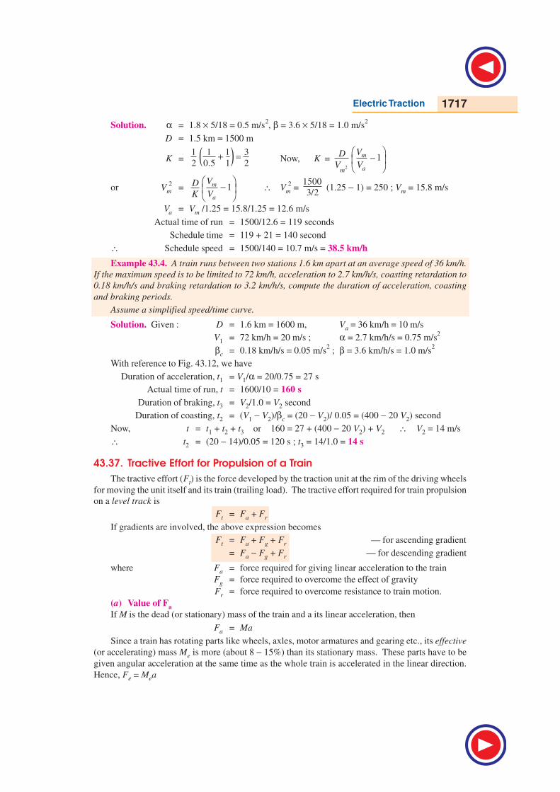
Electric traction provides high starting torque and low
maintenance costs making it the best choice for trains
Electric Traction 1717
Solution. α = 1.8 × 5/18 = 0.5 m/s2, β = 3.6 × 5/18 = 1.0 m/s
2
D = 1.5 km = 1500 m
K = ( )1 1 1 3
2 0.5 1 2+ = Now, K =
2
1m
am
VD
V V
−
or Vm
2= 1m
a
VD
K V
−
∴ Vm
2 =
1500
3/2 (1.25 − 1) = 250 ; Vm = 15.8 m/s
Va = Vm /1.25 = 15.8/1.25 = 12.6 m/s
Actual time of run = 1500/12.6 = 119 seconds
Schedule time = 119 + 21 = 140 second
∴ Schedule speed = 1500/140 = 10.7 m/s = 38.5 km/h
Example 43.4. A train runs between two stations 1.6 km apart at an average speed of 36 km/h.
If the maximum speed is to be limited to 72 km/h, acceleration to 2.7 km/h/s, coasting retardation to
0.18 km/h/s and braking retardation to 3.2 km/h/s, compute the duration of acceleration, coasting
and braking periods.
Assume a simplified speed/time curve.
Solution. Given : D = 1.6 km = 1600 m, Va = 36 km/h = 10 m/s
V1 = 72 km/h = 20 m/s ; α = 2.7 km/h/s = 0.75 m/s2
βc = 0.18 km/h/s = 0.05 m/s2 ; β = 3.6 km/h/s = 1.0 m/s
2
With reference to Fig. 43.12, we have
Duration of acceleration, t1 = V1/α = 20/0.75 = 27 s
Actual time of run, t = 1600/10 = 160 s
Duration of braking, t3 = V2/1.0 = V2 second
Duration of coasting, t2 = (V1 − V2)/βc = (20 − V2)/ 0.05 = (400 − 20 V2) second
Now, t = t1 + t2 + t3 or 160 = 27 + (400 − 20 V2) + V2 ∴ V2 = 14 m/s
∴ t2 = (20 − 14)/0.05 = 120 s ; t3 = 14/1.0 = 14 s
43.37. Tractive Effort for Propulsion of a Train
The tractive effort (Ft) is the force developed by the traction unit at the rim of the driving wheels
for moving the unit itself and its train (trailing load). The tractive effort required for train propulsion
on a level track is
Ft = Fa + Fr
If gradients are involved, the above expression becomes
Ft = Fa + Fg + Fr — for ascending gradient
= Fa − Fg + Fr — for descending gradient
where Fa = force required for giving linear acceleration to the train
Fg = force required to overcome the effect of gravity
Fr = force required to overcome resistance to train motion.
(a) Value of Fa
If M is the dead (or stationary) mass of the train and a its linear acceleration, then
Fa = Ma
Since a train has rotating parts like wheels, axles, motor armatures and gearing etc., its effective
(or accelerating) mass Me is more (about 8 − 15%) than its stationary mass. These parts have to be
given angular acceleration at the same time as the whole train is accelerated in the linear direction.
Hence, Fe = Mea
1718 Electrical Technology
(i) If Me is in kg and α in m/s2, then Fa = Me a newton
(ii) If Me is in tonne and α in km/h/s, then converting them into absolute units, we have
Fa = (1000 Me) × (1000/3600) a = 277.8 Me a newton
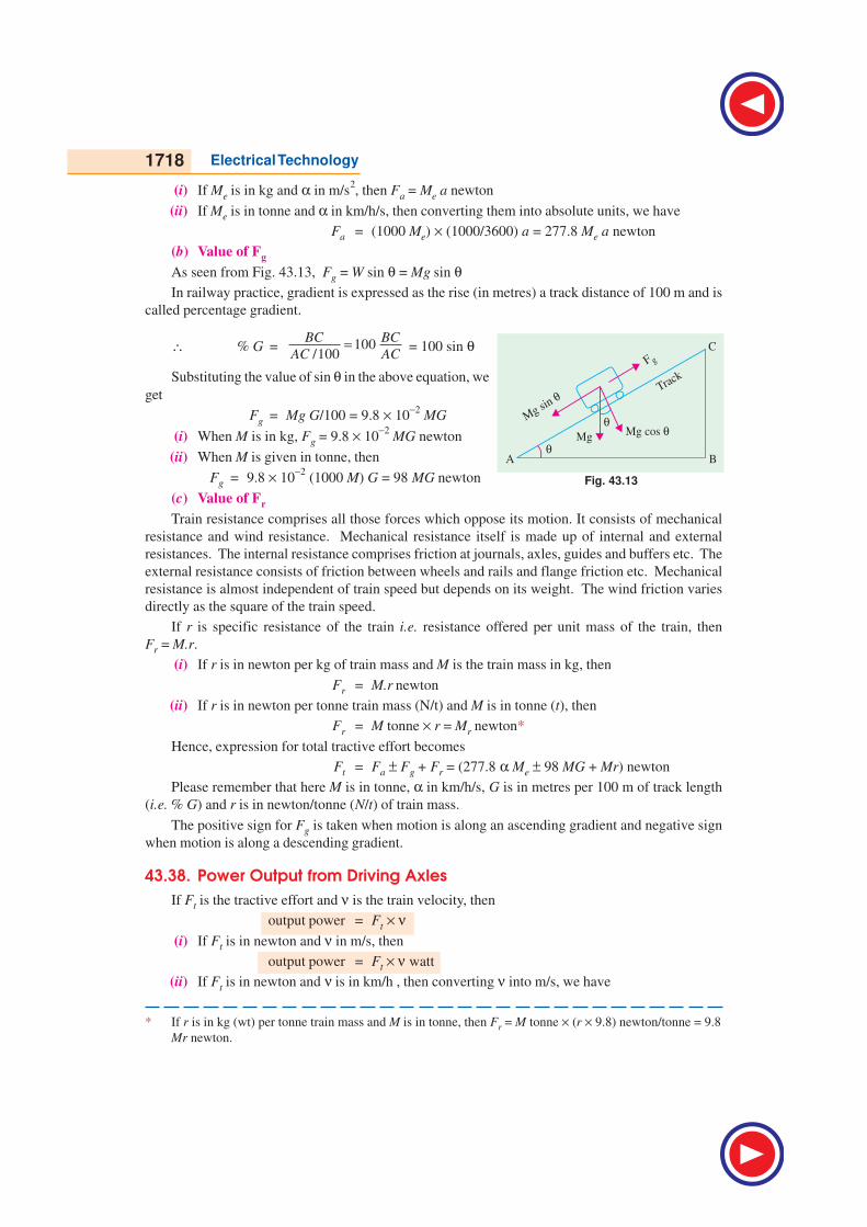
(b) Value of Fg
As seen from Fig. 43.13, Fg = W sin θ = Mg sin θIn railway practice, gradient is expressed as the rise (in metres) a track distance of 100 m and is
called percentage gradient.
∴ % G = 100/100
BC BC
AC AC= = 100 sin θ
Substituting the value of sin θ in the above equation, we
get
Fg = Mg G/100 = 9.8 × 10⁻²
MG
(i) When M is in kg, Fg = 9.8 × 10⁻²
MG newton
(ii) When M is given in tonne, then
Fg = 9.8 × 10⁻²
(1000 M) G = 98 MG newton
(c) Value of Fr
Train resistance comprises all those forces which oppose its motion. It consists of mechanical
resistance and wind resistance. Mechanical resistance itself is made up of internal and external
resistances. The internal resistance comprises friction at journals, axles, guides and buffers etc. The
external resistance consists of friction between wheels and rails and flange friction etc. Mechanical
resistance is almost independent of train speed but depends on its weight. The wind friction varies
directly as the square of the train speed.
If r is specific resistance of the train i.e. resistance offered per unit mass of the train, then
Fr = M.r.
(i) If r is in newton per kg of train mass and M is the train mass in kg, then
Fr = M.r newton
(ii) If r is in newton per tonne train mass (N/t) and M is in tonne (t), then
Fr = M tonne × r = Mr newton*
Hence, expression for total tractive effort becomes
Ft = Fa ± Fg + Fr = (277.8 α Me ± 98 MG + Mr) newton
Please remember that here M is in tonne, α in km/h/s, G is in metres per 100 m of track length
(i.e. % G) and r is in newton/tonne (N/t) of train mass.
The positive sign for Fg is taken when motion is along an ascending gradient and negative sign
when motion is along a descending gradient.
43.38. Power Output from Driving Axles
If Ft is the tractive effort and ν is the train velocity, then
output power = Ft × ν(i) If Ft is in newton and ν in m/s, then
output power = Ft × ν watt
(ii) If Ft is in newton and ν is in km/h , then converting ν into m/s, we have
Fig. 43.13
* If r is in kg (wt) per tonne train mass and M is in tonne, then Fr = M tonne × (r × 9.8) newton/tonne = 9.8
Mr newton.
Electric Traction 1719
output power = ( )1000watt kW
3600 3600t
t
FF
ν× ν =
If η is the efficiency of transmission gear, then power output of motors is
= Ft . ν/η watt — ν in m/s
=3600
tF νη
kW — ν in km/h
43.39. Energy Output from Driving Axles
Energy (like work) is given by the product of power and time.
E = (Ft × ν ) × t = Ft × (ν × t) = Ft × D
where D is the distance travelled in the direction of tractive effort.
Total energy output from driving axles for the run is
E = energy during acceleration + energy during free run
As seen from Fig. 43.11
E = Ft × area OAD + Ft′ × area ABED = Ft × 1
2 Vm t1 + Ft′ ×
1
2 Vm t2
where Ft is the tractive effort during accelerating period and Ft′ that during free-running period.
Incidentally, Ft will consist of all the three components given in Art. 43.37 whereas Ft′ will consist of
(98 MG + Mr) provided there is an ascending gradient.
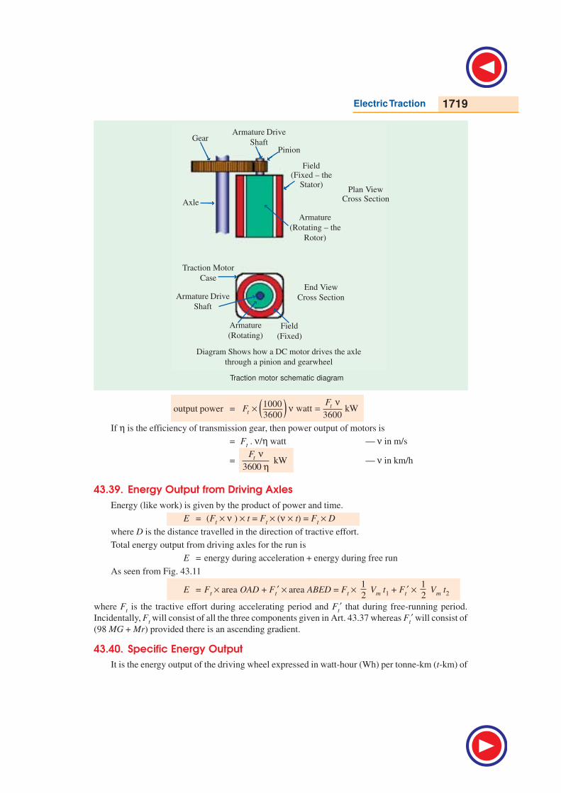
43.40. Specific Energy Output
It is the energy output of the driving wheel expressed in watt-hour (Wh) per tonne-km (t-km) of
Diagram Shows how a DC motor drives the axle
through a pinion and gearwheel
Armature Drive
ShaftPinion
Gear
Axle
Field(Fixed – the
Stator)
Armature
(Rotating – the
Rotor)
End View
Cross Section
Traction Motor
Case
Armature Drive
Shaft
Armature
(Rotating)Field
(Fixed)
Traction motor schematic diagram
Plan ViewCross Section
→→→→→
→→→→→
→→→→→ →→→→→
→→→→→
→→→→→
→→→→→
→→→→→→→→→→
→→→→→
1720 Electrical Technology
the train. It can be found by first converting the energy output into Wh and then dividing it by the
mass of the train in tonne and route distance in km.
Hence, unit of specific energy output generally used in railway work is : Wh/tonne-km
(Wh/t-km).
43.41. Evaluation of Specific Energy Output
We will first calculate the total energy output of the driving axles and then divide it by train mass
in tonne and route length in km to find the specific energy output. It will be presumed that :
(i) there is a gradient of G throughout the run and
(ii) power remains ON upto the end of free run in the case of trapezoidal curve (Fig. 43.11) and
upto the accelerating period in the case of quadrilateral curve (Fig. 43.12).
Now, output of the driving axles is used for the following purposes :
1. for accelerating the train 2. for overcoming the gradient
3. for overcoming train resistance.
(a) Energy required for train acceleration (Ea)
As seen from trapezoidal diagram of Fig. 43.11,
Ea = Fa × distance OAD = 277.8 α Me × 1
2 Vm.t1 joules
= 277.8 α Me × 1
2 Vm × mV
α joules 1
mVt
= α Q
= 277.8 α Me × 10001
.2 3600
m mV V× × α joules
It will be seen that since Vm is in km/h, it has been converted into m/s by multiplying it with the
conversion factor of (1000/3600). In the case of (Vm /t), conversion factors for Vm and a being the
same, they cancel out. Since 1 Wh = 3600 J.
∴ Ea = 277.8 α Me 10001
.2 3600
m mV V× × α Wh = 0.01072
2
m
e
V
M Wh
(b) Energy required for over coming gradient (Eg)
Eg = Fg ××××× D′′′′′where ‘D′ ’ is the total distance over which power remains ON. Its maximum value equals the
distance represented by the area OABE in Fig. 43.11 i.e. from the start to the end of free-running
period in the case of trapezoidal curve [as per assumption (i) above].
Substituting the value of Fg from Art. 43.37, we get
Eg = 98 MG. (1000 D′) joules = 98,000 MGD′ joules
It has been assumed that D′ is in km.
When expressed in Wh, it becomes
Eg = 98,000 MGD′ 1
3600 Wh = 27.25 MGD′ Wh
(c) Energy required for overcoming resistance (Er)
Er = Fr × D′ = M . r × (1000 D′) joules — D′′′′′ in km
=1000
3600
Mr D′ Wh = 0.2778 Mr D′ Wh — D′′′′′ in km
∴ total energy output of the driving axles is

Electric Traction 1721
E = Ea + Eg + Er
= (0.01072 Vm
2/Me + 27.25 MGD′ + 0.2778 Mr D′ Wh
Specific energy output
Espo =E
M D×— D is the total run length
=
2
0.01072 . 27.25 0.2778 Wh/t-kmm eV M D DG r
D M D D
′ ′+ +
It may be noted that if there is no gradient, then
Espo =
2
0.01072 . 0.2778m eV M Dr
D M D
′+
Wh/t-km
Alternative Method
As before, we will consider the trapezoidal speed/time curve. Now, we will calculate energy
output not force-wise but period-wise.
(i) Energy output during accelerating period
Ea = Ft × distance travelled during accelerating period
= Ft × area OAD —Fig. 43.11
= 1
1 1. .
2 2m
t m t m
VF V t F V× =
α
= ( )1 1000. . .
2 3600m
t m
VF V
α joules
= ( )1 1000 1. . . .
2 3600 3600m
t m
VF V
α Wh
Substituting the value of Ft , we get
Ea =2
2
1000.
2(3600)
mV
α(277.8 α Me + 98 MG + Mr) Wh
It must be remembered that during this period, all the three forces are at work (Art. 43.37)
(ii) Energy output during free-running period
Here, work is required only against two forces i.e. gravity and resistance (as mentioned earlier).
Energy Efr = Ft′ × area ABED —Fig. 43.11
= Ft′ × (Vm × t2) = Ft′ × ( )1000
3600 mV . t2 joules
= ( ) ( )2 21000 1 1000 1
Wh . Wh3600 3600 3600 3600t m t mF V t F V t′ ′× × × = ×
= ( ) ( )1000 1000. Wh (98 ) Wh
3600 3600t fr frF D MG Mr D′× = +
where Dfr is the distance in km travelled during the free-running period*
Total energy required is the sum of the above two energies.
∴ E = Ea + Efr
=2
2
1000
2(3600)
mV
α (277.8 α . Me + 98 MG + Mr) +
1000
3600 (98 MG + Mr) Dfr Wh
* Dfr
= velocity in km/h × time in hours
= Vm × (t2/ 3600) because times are always taken in seconds.
1722 Electrical Technology
=2
2
1000
2(3600)
mV
α 277.8 α Me +
2
2
1000.2(3600)
mV
α (98 MG + Mr) +
1000
3600 (98 MG + Mr) . Dfr Wh
= 0.01072 Vm
2 . Me +
1000
3600 (98 MG + Mr)
2
Wh2 3600
mfr
VD
+ α ×
Now,
2
2 3600mV
α ×= 1
1 1. .
2 3600 2 3600m m mV V V
t = α
= distance travelled during accelerating period i.e. Da
∴ E = 0.01072 Vm
2 . Me +
1000
3600 (98 MG + Mr) (Da + Dfr) Wh
= 0.01072 Vm
2 . Me + (27.25 MG + 0.2778 Mr) D′ Wh
It is the same expression as found above.
43.42. Energy Consumption
It equals the total energy input to the traction motors from the supply. It is usually expressed in
Wh which equals 3600 J. It can be found by dividing the energy output of the driving wheels with the
combined efficiency of transmission gear and motor.
∴ energy consumption =output of driving axles
motor gearη × η
43.43. Specific Energy Consumption
It is the energy consumed (in Wh) per tonne mass of the train per km length of the run.
Specific energy consumption,
Espc =total energy consumed in Wh specific energy output
train mass in tonne run length in km=
× ηwhere η = overall efficiency of transmission gear and motor = ηgear × ηmotor
As seen from Art. 43.41, specific energy consumption is
Espc =2
0.01072 . . 27.25 . 0.2778 .m eV M G D r D
D M D D
′ ′+ + η η η Wh/t-km
If no gradient is involved, then specific enrgy consumption is
Espc =2
0.01072 . . 0.2778 .m eV M r D
D M D
′+ η η Wh/t-km
The specific energy consumption of a train running at a given schedule speed is influenced by
1. Distance between stops 2. Acceleration 3. Retardation 4. Maximum speed 5. Type
of train and equipment 6. Track configuration.
43.44. Adhesive Weight
It is given by the total weight carried on the driving wheels. Its value is Wa = x W, where W is
dead weight and x is a fraction varying from 0.6 to 0.8.
43.45. Coefficient of Adhesion
Adhesion between two bodies is due to interlocking of the irregularities of their surfaces in
contact. The adhesive weight of a train is equal to the total weight to be carried on the driving
Electric Traction 1723
wheels. It is less than the dead weight by about 20 to 40%.
If x =adhesive weight,
dead weight aW
W, then, Wa = x W
Let, Ft = tractive effort to slip the wheels
or
= maximum tractive effort possible without wheel slip
Coefficient of adhesion, µa = Ft /Wa
∴ Ft = µa Wa = µa xW = µa x Mg
If M is in tonne, then
Ft = 1000 × 9.8 x µa M = 9800 µa x M newton
It has been found that tractive effort can be increased by increasing the motor torque but only
upto a certain point. Beyond this point, any increase in motor torque does not increase the tractive
effort but merely causes the driving wheels to slip. It is
seen from the above relation that for increasing Ft, it is
not enough to increase the kW rating of the traction
motors alone but the weight on the driving wheels has
also to be increased.
Adhesion also plays an important role in braking.
If braking effort exceeds the adhesive weight of the ve-
hicle, skidding takes place.
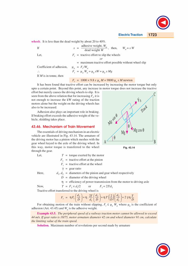
43.46. Mechanism of Train Movement
The essentials of driving mechanism in an electric
vehicle are illustrated in Fig. 43.14. The armature of
the driving motor has a pinion which meshes with the
gear wheel keyed to the axle of the driving wheel. In
this way, motor torque is transferred to the wheel
through the gear.
Let, T = torque exerted by the motor
F1 = tractive effort at the pinion
Ft = tractive effort at the wheel
γ = gear ratio
Here, d1, d2 = diameters of the pinion and gear wheel respectively
D = diameter of the driving wheel
η = efficiency of power transmission from the motor to driving axle
Now, T = F1 × d1/2 or F1 = 2T/d1
Tractive effort transferred to the driving wheel is
Ft = ( )2 2 21
1 1
2 2. 2
d d dT TF T
D d D D d D
η = η = η = γ η
For obtaining motion of the train without slipping, Ft ≤ µa Wa where µa is the coefficient of
adhesion (Art. 43.45) and Wa is the adhesive weight.
Example 43.5. The peripheral speed of a railway traction motor cannot be allowed to exceed
44 m/s. If gear ratio is 18/75, motor armature diameter 42 cm and wheel diameter 91 cm, calculate
the limiting value of the train speed.
Solution. Maximum number of revolutions per second made by armature
Fig. 43.14
1724 Electrical Technology
=armature velocity 44 100
armature circumference 0.42 3= =
πrps.
Maximum number of revolutions per second made by the driving wheel
=100 18
3 75× = 8 rps.
Maximum distance travelled by the driving wheel in one second
= 8 × 0.91 π m/s = 22.88 m/s
Hence, limiting value of train speed
= 22.88 m/s = 22.88 × 18/5 = 82 km/h
Example 43.6. A 250-tonne motor coach driven by four motors takes 20 seconds to attain a
speed of 42 km/h, starting from rest on an ascending gradient of 1 in 80. The gear ratio is 3.5, gear
efficiency 92%, wheel diameter 92 cm train resistance 40 N/t and rotational inertia 10 percent of the
dead weight. Find the torque developed by each motor.
Solution. Ft = (277.8 × Me a + 98 MG + Mr) newton
Now, α = Vm /t1 = 42/20 = 2.1 km/h/s Since gradient is 1 in 80, it becomes 1.25 in
100. Hence, percentage gradient G = 1.25. Also, Me = 1.1 M. The
tractive effort at the driving wheel is
Ft = 277.8 × ( 1.1 × 250) × 2.1 + 98 × 250 × 1.25 + 250 × 40
= 160,430 + 30,625 + 10,000 = 201,055 N
Now, Ft = 2γ ηT/D or 201,055 = 2 × 3.5 × 0.92 × T/0.92 ∴ T = 28,744 N–m
Torque developed by each motor = 28,744/4 = 7,186 N–m
Example 43.7. A 250-tonne motor coach having 4 motors, each developing a torque of 8000 N-m
during acceleration, starts from rest. If up-gradient is 30 in 1000, gear ratio 3.5, gear transmission
efficiency 90%, wheel diameter 90 cm, train resistance 50 N/t, rotational inertia effect 10%, compute
the time taken by the coach to attain a speed of 80 km/h.
If supply voltage is 3000 V and motor efficiency 85%, calculate the current taken during the
acceleration period.
Solution. Tractive effort (Art. 43.46) at the wheel
= 2γ ηT/D = 2 × 3.5 × 0.9 × (8000 × 4)/0.9 = 224,000 N
Also, Ft = (277.8 a Me + 98 MG + Mr) newton
= (277.8 × (1.1 × 250) × a + 98 × 250 × 3 + 250 × 50 N
= (76,395 a + 86,000) N
Equating the two expression for tractive effort, we get
224,000 = 76,395 a + 86,000 ; a = 1.8 km/h/s
Time taken to achieve a speed of 80 km/h is
t1 = Vm /a = 80/1.8 = 44.4 second
Power taken by motors (Art. 41.36) is
= ( )1000. .
3600t t m m
t
F F V VF
× ν ×= =
η η η watt
= 22,000 × 0.2778 × 80/0.85 = 58.56 × 10⁵ W
Total current drawn = 55.56 × 10⁵/3000 = 1952 A
Current drawn/motor = 1952/4 = 488 A.
Electric Traction 1725
Example 43.8. A goods train weighing 500 tonne is to be hauled by a locomotive up an ascend-
ing gradient of 2% with an acceleration of 1 km/h/s. If coefficient of adhesion is 0.25, train resis-
tance 40 N/t and effect of rotational inertia 10%, find the weight of locomotive and number of axles
if load is not to increase beyond 21 tonne/axle.
Solution. It should be clearly understood that a train weighing 500 tonne has a mass of 500
(Art. 43.33).
Tractive effort required is
Ft = (277.8 a Me + 98 MG + Mr) newton = 277.8 . 98eMM a G r
M
+ + newton
= M (277.8 × 1 × 1.1 + 98 × 2 + 40) = 541.6 M newton
If ML is the mass of the locomotive, then
Ft = 541.6 (M + ML) = 541.6 (500 + ML) newton
Maximum tractive effort (Art. 43.45) is given by
Ft = 1000 µa ML . g = 1000 × 0.25 ML × 9.8 — x = 1
∴ 541.6 (500 + ML) = 1000 × 0.25 ML × 9.8 ∴ ML = 142 tonne
Hence, weight of the locomotive is 142 tonne. Since, weight per axle is not to exceed 21 tonne,
the number of axles required is = 142/21 = 7.
Example 43.9. An electric locomotive weighing 100 tonne can just accelerate a train of 500
tonne (trailing weight) with an acceleration of 1 km/h/s on an up-gradient of 0.1%. Train resistance
is 45 N/t and rotational inertia is 10%. If this locomotive is helped by another locomotive of weight
120 tonne, find :
(i) the trailing weight that can now be hauled up the same gradient under the same conditions.
(ii) the maximum gradient, if the trailing hauled load remains unchanged.
Assume adhesive weight expressed as percentage of total dead weight as 0.8 for both locomo-
tives. (Utilization of Elect. Power ; AMIE, Summer)
Solution. Dead weight of the train and locomotive combined = (100 + 500) = 600 tonne. Same
is the value of the dead mass.
∴ Ft = (277.8a Me + 98 MG + Mr) newton
= 277.8 × 1 × (1.1 × 600) + 98 × 600 × 0.1 + 600 × 45 = 216,228 N
Maximum tractive effort (Art. 43.45) of the first locomotive
= 9800x µaML = 9800 × 0.8 × µa × 1000 = 784,000 µa
∴ 784,000µa = 216,288 ; µa = 0.276
With two locomotive, ML′ = (100 + 120) = 220 tonne
∴ Ft = 9800 x µaML′ = 9800 × 0.8 × 0.276 × 220 = 476,045 N
(i) Let trailing load which the two combined locomotives can haul be M tonne. In that case,
total dead mass becomes M = (100 + 120 + M) = (220 + M) tonne. Tractive effort required is
= (277.8 Me′ + 98 M′G + M′r) newton
= M′ (277.8 × 1 × 1.1 + 98 × 0.1 + 45) = 360.4 M′ newton
∴ 360.4 M′ = 476,045; M′ = 1321 tonne ∴ trailing load, M = 1321 − 220 = 1101 tonne
(ii) Total hauled load = 500 + 100 + 120 = 720 tonne
Let G be the value of maximum percentage gradient. Then
Ft = (277.8 a Me + 98MG + Mr) newton = 277.8 98eMM a G r
M
+ + newton
1726 Electrical Technology
= 720 (277.8 × 1 × 1.1 + 98G + 45) newton = (252,418 + 70,560 G) newton
Equating it with the combined tractive effort of the two locomotive as calculated above, we have,
476,045 = 252,418 + 70,560 G ∴ G = 3.17 percent
Example 43.10. The average distance between stops on a level section of a railway is 1.25 km.
Motor-coach train weighing 200 tonne has a schedule speed of 30 km/h, the duration of stops being
30 seconds. The acceleration is 1.9 km/h/s and the braking retardation is 3.2 km/h/s. Train resis-
tance to traction is 45 N/t. Allowance for rotational inertia is 10%. Calculate the specific energy
output in Wh/t-km. Assume a trapezoidal speed/time curve. (Elect. Power, Bombay Univ.)
Solution. α = 1.9 × 5/18 = 9.5/18 m/s2 : β = 3.2 × 5/18 = 8/9 m/s
2
K = (α + β)/2αβ = 1.5 ; D = 1.25 km = 1250 m
Schedule time = 1.25 × 3600/30 = 150 s. Running time = 150 − 30 = 120 s
Vm =
2 24 120 120 4 1.5 1250
2 2 1.5
t t KD
K
− − − − × ×=
× = 10.4 m/s = 37.4 km/h
Braking distance D = Vm
2/2β = 10.42/2 × (8/9) = 0.06 km
∴ D′ = D – braking distance = 1.25 − 0.06 = 1.19 km
Specific energy output = 0.01072 2
.m eV M
D M + 0.2778 r
D
D
′
= 0.01072 × 2
37.4 1.191.1 0.2778 50
1.25 1.25× + × × Wh/t-km
= 16.5 + 13.2 = 29.7 Wh/t-km
Example. 43.11. A 300-tonne EMU is started with a uniform acceleration and reaches a speed
of 40 km/h in 24 seconds on a level track. Assuming trapezoidal speed/time curve, find specific
energy consumption if rotational inertia is 8%, retardation is 3 km/h/s, distance between stops is
3 km, motor efficiency is 0.9 and train resistance is 40 N/tonne.
(Elect. Traction, AMIE Summer)
Solution. First of all, let us find D′ – the distance upto which energy is consumed from the
supply. It is the distance travelled upto the end of free-running period. It is equal to the total distance
minus the distance travelled during braking.
Braking time, t2 = Vm/ β = 40/3 = 13.33 second
Distance travelled during braking period
= ( )31 1 13.33
402 2 3600mV t = × × = 0.074 km
∴ D′ = D – braking distance = 3 − 0.074 = 2.926 km
Since, Me/M = 1.08, using the relation derived in Art. 43.43, we get the value of specific energy
consumption as
=
2
0.01072 . 0.2778m eV M r D
D M D
′+ η η Wh/t-km
=2
40 49 2.9260.01072 1.08 0.2778
0.9 3 0.9 3
× × + × × ×
= 21.6 Wh/t-km.
Example 43.12. An electric train accelerates uniformly from rest to a speed of 50 km/h in 25
seconds. It then coasts for 70 seconds against a constant resistance of 60 N/t and is then braked to
rest with uniform retardation of 3.0 km/h/s in 12 seconds. Compute
(i) uniform acceleration (ii) coasting retardation
Electric Traction 1727
(iii) schedule speed if station stops are of 20-second duration
Allow 10% for rotational inertia. How will the schedule speed be affected if duration of stops is
reduced to 15 seconds, other factors remaining the same ?
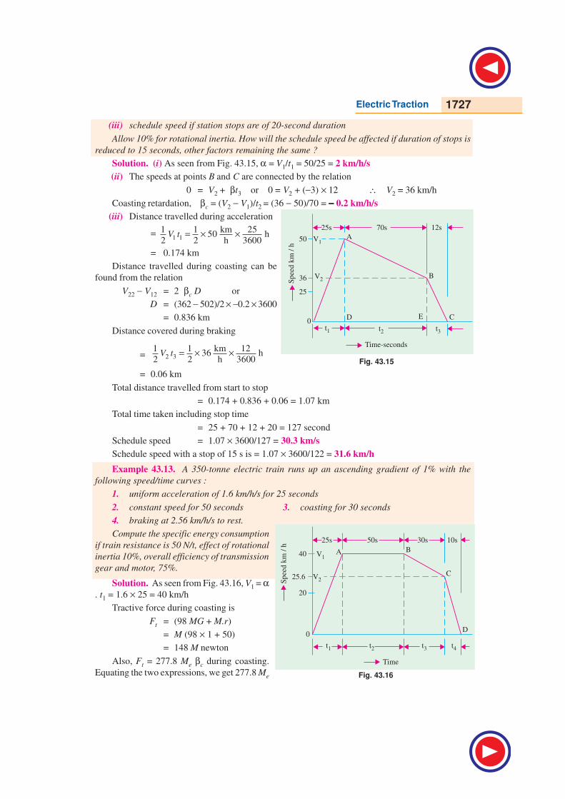
Solution. (i) As seen from Fig. 43.15, α = V1/t1 = 50/25 = 2 km/h/s
(ii) The speeds at points B and C are connected by the relation
0 = V2 + βt3 or 0 = V2 + (−3) × 12 ∴ V2 = 36 km/h
Coasting retardation, βc = (V2 − V1)/t2 = (36 − 50)/70 = −−−−− 0.2 km/h/s
(iii) Distance travelled during acceleration
= 1 1
1 1 km 2550 h
2 2 h 3600V t = × ×
= 0.174 km
Distance travelled during coasting can be
found from the relation
V22 − V12 = 2 βc D or
D = (362 − 502)/2 × −0.2 × 3600
= 0.836 km
Distance covered during braking
= 2 31 1 km 12
36 h2 2 h 3600
V t = × ×
= 0.06 km
Total distance travelled from start to stop
= 0.174 + 0.836 + 0.06 = 1.07 km
Total time taken including stop time
= 25 + 70 + 12 + 20 = 127 second
Schedule speed = 1.07 × 3600/127 = 30.3 km/s
Schedule speed with a stop of 15 s is = 1.07 × 3600/122 = 31.6 km/h
Example 43.13. A 350-tonne electric train runs up an ascending gradient of 1% with the
following speed/time curves :
1. uniform acceleration of 1.6 km/h/s for 25 seconds
2. constant speed for 50 seconds 3. coasting for 30 seconds
4. braking at 2.56 km/h/s to rest.
Compute the specific energy consumption
if train resistance is 50 N/t, effect of rotational
inertia 10%, overall efficiency of transmission
gear and motor, 75%.
Solution. As seen from Fig. 43.16, V1 = α. t1 = 1.6 × 25 = 40 km/h
Tractive force during coasting is
Ft = (98 MG + M.r)
= M (98 × 1 + 50)
= 148 M newton
Also, Ft = 277.8 Me βc during coasting.
Equating the two expressions, we get 277.8 Me
Fig. 43.15
Fig. 43.16
1728 Electrical Technology
. βc = 148 M
∴ βc =148 148 1
277.8 277.8 1.1e
M
M× = × ;
βc = 0.48 km/h/s
Now, V2 = V1 + βc t3= 40 + (−0.48) × 30
= 25.6 km/h
t4 = V2/ β = 25.6/2.56 = 10 second
Distance travelled during acceleration period = 1 km 25
40 h2 h 3600
× × = 0.139 km
Distance travelled during constant speed period is = V1 × t2 = 40 × 50/3600 = 0.555 km
Distance travelled during coasting = 1 23
40 25.6 30
2 2 3600
V Vt
+ + × = ×
= 0.273 km
Distance travelled during braking = 1
2 V2t4 =
1
2 × 25.6 ×
10
3600 = 0.035 km
Total distance between stops = 0.139 + 0.555 + 0.273 + 0.035 = 1.002 km
Distance travelled during acceleration and free-running period is
D′ = 0.139 + 0.555 = 0.694 km
Specific energy consumption (Art. 43.43) is
=
2
0.01072 . 27.25 . 0.2778 .m eV M G D r D
D M D D
′ ′+ + η η η Wh/t-km
=2
40 1 0.694 50 0.6940.01072 1.1 27.25 0.2778
0.75 1.002 0.75 1.002 0.75 1.002
× × + × × + × × ×
= 25.1 + 25.2 + 12.8 = 63.1 Wh/t-km
Example 43.14. An ore-carrying train weighing 5000 tonne is to be hauled down a gradient of
1 : 50 at a maximum speed of 30 km/h and started on a level track at an acceleration of 0.29 km/h/s.
How many locomotives, each weighing 75 tonne, will have to be employed ?
Train resistance during starting = 29.4 N/t, Train resistance at 30 km/h = 49 N/t
Coefficient of adhesion = 0.3, Rotational inertia = 10%
(Utilization of Elect. Power, AMIE)
Solution. Downward force due to gravity
= Mg sin θ = (5000 × 1000) × 9.8 × 1/50 = 980,000 N
Train resistance = 49 × 5000 = 245,000 N
Braking force to be supplied by brakes = 980,000 − 245,000 = 735,000 N
Max. braking force which one locomotive can provide
= 1000 µa Mg newton —M in tonne
= 1000 × 0.3 × 75 × 9.8 = 220,500 N
No. of locomotives required for braking = 735,000/220,500 = 3.33
Since fraction is meaningless, it means that 4 locomotives are needed.
Tractive effort required to haul the train on level track
Electric Traction 1729
= (277.8 α Me + Mr) newton
= 277.8 × (5000 × 1.1) × 0.29 + 5000 × 29.4 = 590,090 N
No. of locomotives required = 590,090/220,500 = 2.68 ≅ 3
It means that 4 locomotives are enough to look after braking as well as starting.
Example 43.15. A 200-tonne electric train runs according to the following quadrilateral speed/
time curve:
1. uniform acceleration from rest at 2 km/h/s for 30 seconds
2. coasting for 50 seconds
3. duration of braking : 15 seconds
If up-gradient is = 1%, train resistance = 40 N/t, rotational inertia effect = 10%, duration of
stops = 15 s and overall efficiency of gear and motor = 75%, find
(i) schedule speed (ii) specific energy consumption (iii) how will the value of specific energy
consumption change if there is a down-gradient of 1% rather than the up-gradient ?
(Electric Traction Punjab Univ. 1993)
Solution. V1 = α. t1 = 2 × 30 = 60 km/h/s
During coasting, gravity component and train resistance will cause coasting retardation βc.
Retarding force = (98 MG + Mr) newton = (98 × 200 × 1.0 + 200 × 40) = 27,600 N
As per Art, 43.37, 277.8 Me. βc = 27,600 or 277.8 × (200 × 1.1) × βc = 27,600
∴ βc = 0.45 km/h/s
Now, V2 = V1 + βc t2 or V2 = 60 + (− 0.45) × 50 = 37.5 km/h
Braking retardation β = V2/t3 = 37.5/15 = 2.5 km/h/s
Distance travelled during acceleration (area OAD in Fig. 43.17)
= ( )1 1
1 1 3060
2 2 3600V t = × × = 0.25 km
Distance travelled during coasting
= area ABED = 1 22
60 37.5 50
2 2 3600
V Vt
+ + × = × = 0.677 km
Distance travelled during braking
= area BCE = 2 31 1 15
37.52 2 3600
V t = × × = 0.078 km
Total distance travelled, D = 0.25 + 0.677 + 0.078 = 1.005 km
Total schedule time = 30 + 50 + 15 + 15 = 110 s
(i) ∴ Schedule speed = 1.005
110 / 3600 = 32.9 km/h
(ii) As per Art. 43.43, specific energy consumption
=
2
0.01072 . 27.25 . 0.2778 . .m eV M G D r D
D M D D
′ ′+ + η η η Wh/t-km
=2
60 1 0.25 40 0.250.01072 1.1 27.25 0.2778
0.75 1.005 0.75 1.005 0.75 1.005
× × + × × + × × ×
Wh/t-km
(iii) the speed/time curve for this case is shown in Fig. 43.18. As before, V1 = 60 km/h. Here, we
will take G = −1%
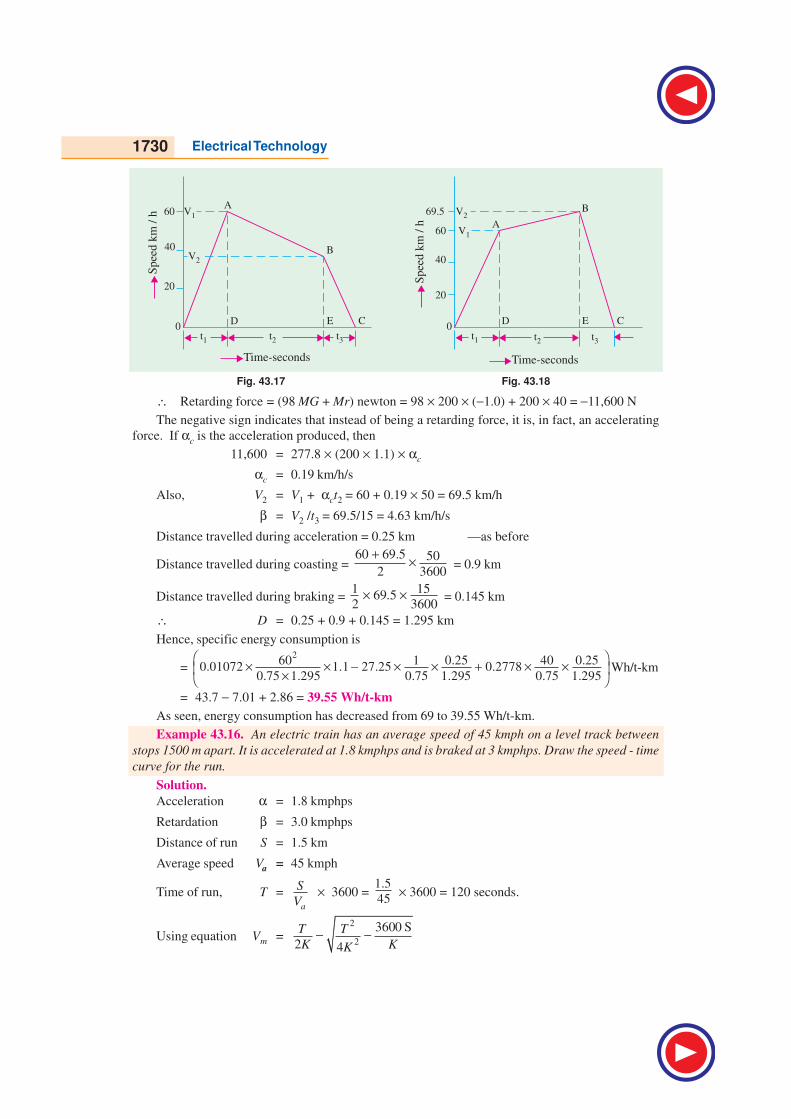
1730 Electrical Technology
Fig. 43.17 Fig. 43.18
∴ Retarding force = (98 MG + Mr) newton = 98 × 200 × (−1.0) + 200 × 40 = −11,600 N
The negative sign indicates that instead of being a retarding force, it is, in fact, an accelerating
force. If αc is the acceleration produced, then
11,600 = 277.8 × (200 × 1.1) × αc
αc = 0.19 km/h/s
Also, V2 = V1 + αct2 = 60 + 0.19 × 50 = 69.5 km/h
β = V2 /t3 = 69.5/15 = 4.63 km/h/s
Distance travelled during acceleration = 0.25 km —as before
Distance travelled during coasting = 60 69.5 50
2 3600
+ × = 0.9 km
Distance travelled during braking = 1 15
69.52 3600
× × = 0.145 km
∴ D = 0.25 + 0.9 + 0.145 = 1.295 km
Hence, specific energy consumption is
= 2
60 1 0.25 40 0.250.01072 1.1 27.25 0.2778
0.75 1.295 0.75 1.295 0.75 1.295
× × − × × + × × ×
Wh/t-km
= 43.7 − 7.01 + 2.86 = 39.55 Wh/t-km
As seen, energy consumption has decreased from 69 to 39.55 Wh/t-km.
Example 43.16. An electric train has an average speed of 45 kmph on a level track between
stops 1500 m apart. It is accelerated at 1.8 kmphps and is braked at 3 kmphps. Draw the speed - time
curve for the run.
Solution.
Acceleration α = 1.8 kmphps
Retardation β = 3.0 kmphps
Distance of run S = 1.5 km
Average speed Va = 45 kmph
Time of run, T =a
S
V × 3600 =
1.5
45 × 3600 = 120 seconds.
Using equation Vm =2
2
3600 S
2 4
T T
K KK− −
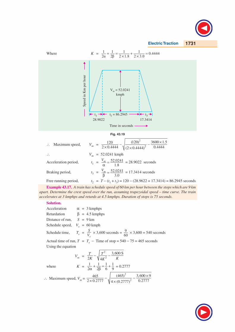
Electric Traction 1731
Where K =1 1 1 1
0.44442 + = + =
× ×
Fig. 43.19
∴ Maximum speed, Vm =2
2
3600 1.5(120)120
2 0.4444 0.4444(2 0.4444)
×− −× ×
∴ Vm = 52.0241 kmph
Acceleration period, t1 = 52.0241
1.8mV
=α
= 28.9022 seconds
Braking period, t3 = 52.0241
3.0mV
=β
= 17.3414 seconds
Free running period, t2 = T − (t1 + t3) = 120 − (28.9622 + 17.3414) = 86.2945 seconds
Example 43.17. A train has schedule speed of 60 km per hour between the stops which are 9 km
apart. Determine the crest speed over the run, assuming trapezoidal speed – time curve. The train
accelerates at 3 kmphps and retards at 4.5 kmphps. Duration of stops is 75 seconds.
Solution.
Acceleration α = 3 kmphps
Retardation β = 4.5 kmphps
Distance of run, S = 9 km
Schedule speed, Vs = 60 kmph
Schedule time, Ts =s
S
V × 3,600 seconds =
9
60 × 3,600 = 540 seconds
Actual time of run, T = Ts − Time of stop = 540 − 75 = 465 seconds
Using the equation
Vm =2
2
3,600 S
2 4
T T
K KK− −
where K =1 1 1 1
2 2 6 9+ = +
α β = 0.2777
∴ Maximum speed, Vm =
2
2
3,600 9(465)465
2 0.2777 0.27774 (0.2777)
×− −× ×
1732 Electrical Technology
Vm = 837 − 700569 116640−
∴ Vm = 72.8475 kmph
Example 43.18. An electric train is to have acceleration and braking retardation of 1.2 km/
hour/sec and 4.8 km/hour/sec respectively. If the ratio of maximum to average speed is 1.6 and time
for stops 35 seconds, find schedule speed for a run of 3 km. Assume simplified trapezoidal speed-
time curve.
Solution.
Acceleration α = 1.2 kmphps
Retardation β = 4.8 kmphps
Distance of run, S = 3 km
Let the actual time of run be T seconds
Average speed, Va =3,600 S 3,600 3 10800
T T T
×= = kmph
Maximum speed, Vm =10800 17280
1.6T T
× = kmph
Since 2 1 1
3,600 S2 2m mV V T
+ − + α β = 0
∴ Vm
2=
172803600 33,600 S
1 1 1 1
2 2 2 1.2 2 4.8
mTV T T
− ×−=
+ +α β × ×
or Vm = 111.5419 kmph
and Va = 111.5419
1.5 1.5mV
= = 74.3613 kmph
Actual time of run T =3,600 S 3600 3
74.3613aV
×= = 145.2369 seconds
Schedule time, Ts = Actual time of run + Time of stop = 145.2369 + 35 j 180 seconds
∴ Schedule speed, Vs =3,600 3 3600
180s
S
T
× ×= = 60 kmph
Example 43.19. An electric train has a schedule speed of 25 kmph between stations 800 m
apart. The duration of stop is 20 seconds, the maximum speed is 20 percent higher than the average
running speed and the braking retardation is 3 kmphps. Calculate the rate of acceleration required
to operate this service.
Solution.
Schedule speed, Vs = 25 kmph
Distance of run, S = 800 metres = 0.8 km
Retardation, β = 3 kmphps
Schedule time of run, Ts =3,600 3600 0.8
25
S
T
× ×= = 115.2 seconds
Actual time of run, T = Ts − duration of stop = 115.2 − 20 = 95.2 seconds
Average speed, Va =3,600 3600 0.8
95.2
S
T
× ×= = 30.25 kmphs
Maximum speed, Vm = 1.2 Va = 1.2 × 30.25 = 36.3 kmph
Electric Traction 1733
Since 2 1 1
3,6002 2m mV V T S + − + α β
= 0
∴ 1 1
2 2+
α β = 2
3,600m
m
V T S
V
−
or1 1
2 2 3+
α × =2
36.3 95.2 3,600 0.8
(36.3)
× − × = 0.4369
or α = 1.85 kmphps
Example 43.20. A suburban electric train has a maximum speed of 80 kmph. The schedule
speed including a station stop of 35 seconds is 50 kmph. If the acceleration is 1.5 kmphps, find the
value of retardation when the average distance between stops is 5 km.
Solution.
Schedule speed, Vs = 50 kmph
Distance of run, S = 5 km
Acceleration, α = 1.5 kmphps
Maximum speed, Vm = 80 kmph
Duration of stop = 35 seconds
Schedule time of run, Ts =3,600 3,600 5
50s
S
V
× ×= = 360 seconds
Actual time of run, T = 2
duration of stops
m
T
V
− = 360 − 30 = 330 seconds
Since 2 1 1
2 2mV + α β
− Vm T + 3,600 S = 0
or1 1
2 2+
α β =2
80 330 3,600 53,600
(80)m
V T S× − ×− = = 1.3125
or1
2β =1 1
1.3125 1.31252 2 1.5
− = −α × = 0.9792
or β =1
2 0.9792× = 0.51064 kmphps
Example 43.21. A train is required to run between two stations 1.6 km apart at the average
speed of 40 kmph. The run is to be made to a simplified quadrilateral speed-time curve. If the maxi-
mum speed is to be limited to 64 kmph, acceleration to 2.0 kmphps and coasting and braking retar-
dation to 0.16 kmphps and 3.2 kmphps respectively, determine the duration of acceleration, coasting
and braking periods.
Solution.
Distance of run, S = 1.6 km
Average speed, Va = 40 kmph
Maximum speed, Vm = 64 kmph
Acceleration, α = 2.0 kmphps
Coasting retardation, βC = 0.16 kmphps
Braking retardation, β = 3.2 kmphps
Duration of acceleration, t1 =64
2.0mV=
α = 32 seconds
1734 Electrical Technology
Actual time of run, T =3,600 3,600 1.6
40a
S
V
×= = 144 seconds
Let the speed before applying brakes be V2
then duration of coasting, t2 =2 2
64
0.16m
c
V V V− −=
β seconds
Duration of braking, t3 = 2 2
3.2
V V=
β seconds
Since actual time of run, T = t1 + t2 + t3
∴ 144 = 32 + 2 264
0.16 3.2
V V−+
or V2 ( )1 1
0.16 3.2− = 32 + 400 − 144
or V2 =288
6.25 0.3125− = 48.5 kmph
Duration of coasting, t2
=2 64 48.5
0.16m
c
V V− −=β = 96.85 seconds
Duration of braking, t3
= 2 48.5
3.2
V=
β = 15.15 seconds
43.47.43.47.43.47.43.47.43.47. General F General F General F General F General Feaeaeaeaeaturturturturtures of es of es of es of es of TTTTTraction Motorraction Motorraction Motorraction Motorraction Motor
Electric Features
- High starting torque
- Series Speed - Torque characteristic
- Simple speed control
- Possibility of dynamic/ regenerative braking
- Good commutation under rapid fluctuations of supply voltage.
Mechanical Features
- Robustness and ability to withstand continuous vibrations.
- Minimum weight and overall dimensions
- Protection against dirt and dust
No type of motor completely fulfills all these requirements. Motors, which have been found
satisfactory are D.C. series for D.C. systems and A.C. series for A.C. systems. While using A.C. three
phase motors are used. With the advent of Power Electronics it is very easy to convert single phase
A.C. supply drawn from pantograph to three phase A.C.
43.48.43.48.43.48.43.48.43.48. Speed - Speed - Speed - Speed - Speed - TTTTTorororororque Characterque Characterque Characterque Characterque Characteristic of Distic of Distic of Distic of Distic of D.C..C..C..C..C. Motor Motor Motor Motor Motor
V = Eb + Ia Ra
V . Ia = Eb . Ia + Ia
2 Ra
where Eb Ia = Power input to armature = Electrical power converted into mechanical power at the
shaft of motor.
Mechanical Power = T . ω = T × 2
60
Nπ
∴ 2
60
NTπ= Eb . Ia∴ T =
609.55
2b a b aE I E I
N N=
πBut Eb =
60
ZNP
A
φ
Electric Traction 1735
∴ T = 9.55 9.5560 60
a aI IZNP ZP
A N A
φ φ=
= 0.1592 × φ × aI
ZA
P Nw-m
∴ Torque T = 0.1592 × flux per pole × armature amp. conductors × Number of poles
Also speed ‘N’ can be calculated as:
Eb = 60
ZNP
A
φ∴ N =
( )60bE
AZPφ
N =( ) 60
a aV I R A
ZP
−φ ∴ N ∝
a aV I R−φ
But T = 9.55 60
aIZP
A
φ from the equation of torque
∴a
T
I = 9.559.55 60
60aIZP A
A T ZP
φ⇒ =
φ Put this value in the above equation of N
∴ N =( ) 9.55
a a aV I R I
T
− ×
Speed N =9.55 ( )
/a a
a
V I R
T I
−
The torque - current and speed - torque curves for D.C. motors are shown in Fig. 43.20 (a) and
(b) respectively.
Fig. 43.20
43.49. Parallel Operation of Series Motorswith Unequal Wheel Diameter
An electric locomotive uses more than one mo-
tor. Each motor drives different set of axles and wheels.
Due to wear and tear the diameter of wheels become
different, after a long service. But the linear speed of
locomotive and wheels will be the same. Therefore,
motor speeds will be different due to difference in di-
ameter of wheels driven by them as shown in Fig.
43.21. Therefore, when the motors are connected in
parallel they will not share the torques equally, as the
current shared by them will be different.
Fig. 43.21
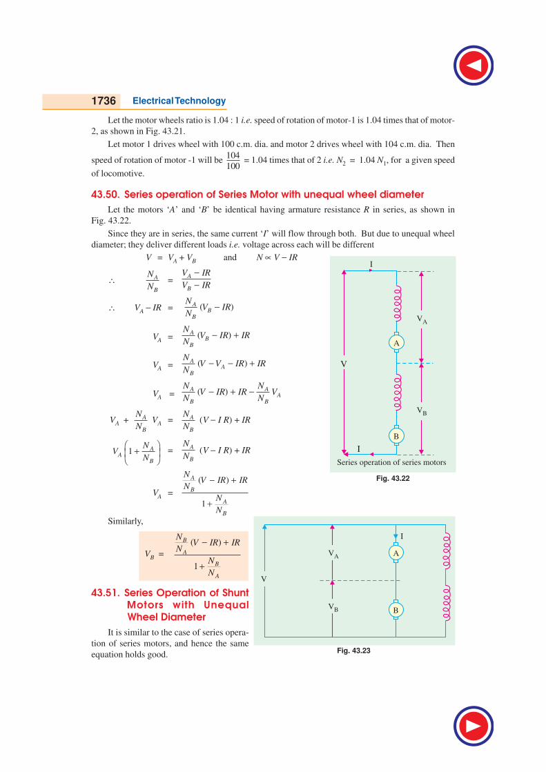
1736 Electrical Technology
Let the motor wheels ratio is 1.04 : 1 i.e. speed of rotation of motor-1 is 1.04 times that of motor-
2, as shown in Fig. 43.21.
Let motor 1 drives wheel with 100 c.m. dia. and motor 2 drives wheel with 104 c.m. dia. Then
speed of rotation of motor -1 will be 104
100 = 1.04 times that of 2 i.e. N2 = 1.04 N1, for a given speed
of locomotive.
43.50. Series operation of Series Motor with unequal wheel diameter
Let the motors ‘A’ and ‘B’ be identical having armature resistance R in series, as shown in
Fig. 43.22.
Since they are in series, the same current ‘I’ will flow through both. But due to unequal wheel
diameter; they deliver different loads i.e. voltage across each will be different
V = VA + VB and N ∝ V − IR
∴ A
B
N
N=
A
B
V IR
V IR
−−
∴ VA − IR = ( )AB
B
NV IR
N−
VA = ( )AB
B
NV IR IR
N− +
VA = ( )AA
B
NV V IR IR
N− − +
VA =( )A A
AB B
N NV IR IR V
N N− + −
VA + A
B
N
N VA = A
B
N
N (V − I R) + IR
1 AA
B
NV
N
+
=
A
B
N
N (V − I R) + IR
VA =
( )
1
A
B
A
B
NV IR IR
N
N
N
− +
+
Similarly,
VB =
( )
1
B
A
B
A
NV IR IR
N
N
N
− +
+
43.51. Series Operation of Shunt Motors with Unequal
Wheel Diameter
It is similar to the case of series opera-
tion of series motors, and hence the same
equation holds good.Fig. 43.23
Fig. 43.22

Electric Traction 1737
43.52. Parallel Operation of Shunt Motors with Unequal Wheel Diameter
As seen from the Fig. 43.24, a small difference in speeds of two motors, causes motors to be
loaded very unequally due to flat speed current curve of D.C. shunt motor.
Fig. 43.24
Example 43.22. The torque-armature current characteristics of a series traction motor are
given as:
Armature Current (amp) : 5 10 15 20 25 30 35 40
Torque (N-m) : 20 50 100 155 215 290 360 430
The motor resistance is 0.3Ω. If this motor is connected across 230 V, deduce the speed arma-
ture current characteristics.
Solution.
Supply voltage, V = 230 V.
Total Resistance of series motor Rm = Ra + Rse = 0.3 Ω.
Armature current,
Ia in amperes 5 10 15 20 25 30 35 40
Torque, T in N-m 20 50 100 155 215 290 360 430
Back e.m.f., Eb =
(V − IaR
m) in volts 228.5 227.0 225.5 224.0 222.5 221.0 219.5 218.0
Speed, Na
9.55 ( )a ma
V I RI
T
−545 434 323 276 247 218 204 194
in R.P.M.
The deduced speed-armature current characteristic is shown in Fig. 43.25.
Example 43.23. The following figures give the magnetization curve of d.c. series motor when
working as a separately excited generator at 600 rpm.:
Field Current (amperes) : 20 40 60 80
E.M.F. (volts) : 215 381 485 550
The total resistance of the motor is 0.8 ohm. Deduce the speed – torque curve for this motor
when operating at a constant voltage of 600 volts.
Solution.
Voltage applied across the motor, V = 600 volts
Resistance of the motor, Rm = (Ra + Rse ) = 0.8 ΩSpeed, N1 = 600 r.p.m.
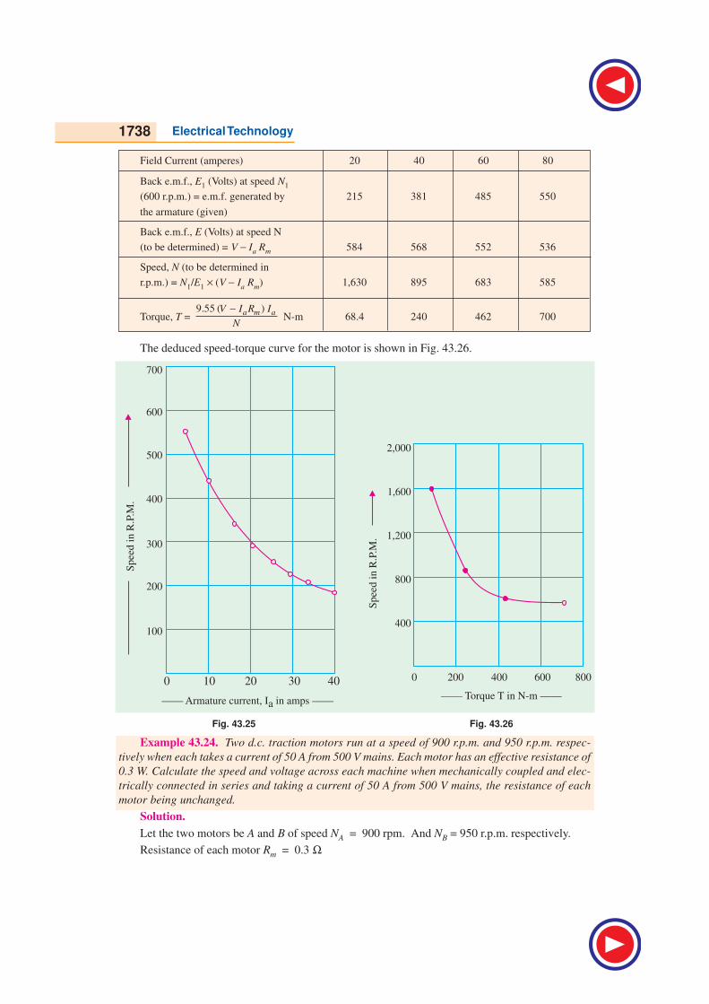
1738 Electrical Technology
Field Current (amperes) 20 40 60 80
Back e.m.f., E1 (Volts) at speed N1
(600 r.p.m.) = e.m.f. generated by 215 381 485 550
the armature (given)
Back e.m.f., E (Volts) at speed N
(to be determined) = V − Ia Rm 584 568 552 536
Speed, N (to be determined in
r.p.m.) = N1/E
1 × (V − I
a R
m) 1,630 895 683 585
Torque, T = 9.55 ( )a m aV I R I
N
−N-m 68.4 240 462 700
The deduced speed-torque curve for the motor is shown in Fig. 43.26.
Fig. 43.25 Fig. 43.26
Example 43.24. Two d.c. traction motors run at a speed of 900 r.p.m. and 950 r.p.m. respec-
tively when each takes a current of 50 A from 500 V mains. Each motor has an effective resistance of
0.3 W. Calculate the speed and voltage across each machine when mechanically coupled and elec-
trically connected in series and taking a current of 50 A from 500 V mains, the resistance of each
motor being unchanged.
Solution.
Let the two motors be A and B of speed NA = 900 rpm. And NB = 950 r.p.m. respectively.
Resistance of each motor Rm = 0.3 Ω
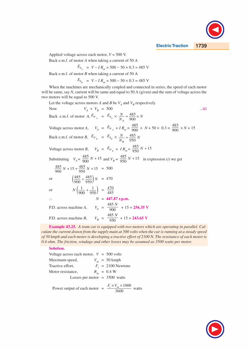
Electric Traction 1739
Applied voltage across each motor, V = 500 V.
Back e.m.f. of motor A when taking a current of 50 A
AbE = V − I Rm = 500 − 50 × 0.3 = 485 V
Back e.m.f. of motor B when taking a current of 50 A
BbE = V − I Rm = 500 − 50 × 0.3 = 485 V
When the machines are mechanically coupled and connected in series, the speed of each motor
will be same, say N, current will be same and equal to 50 A (given) and the sum of voltage across the
two motors will be equal to 500 V.
Let the voltage across motors A and B be VA and VB respectively
Now VA + VB = 500 ...(i)
Back e.m.f. of motor A,A
bE ′ =A
bE × 485
900A
NN
N= ×
Voltage across motor A, VA =A
bE ′ + I Rm = 485
900 × N + 50 × 0.3 =
485
900 × N + 15
Back e.m.f. of motor B,B
bE ′ =B
bE × 485
950B
NN
N=
Voltage across motor B, VB =B
bE ′ + I Rm = 485
15950
N +
Substituting VA = 485
15900
N + and VB = 485
15950
N + in expression (i) we get
485 48515 15
900 950N N+ + + = 500
or ( )485 485
900 950N+ = 470
or ( )1 1
900 950N + =
470
485
∴ N = 447.87 r.p.m.
P.D. across machine A, VA =485
900
N + 15 = 256.35 V
P.D. across machine B, VB =485
950
N + 15 = 243.65 V
Example 43.25. A tram car is equipped with two motors which are operating in parallel. Cal-
culate the current drawn from the supply main at 500 volts when the car is running at a steady speed
of 50 kmph and each motor is developing a tractive effort of 2100 N. The resistance of each motor is
0.4 ohm. The friction, windage and other losses may be assumed as 3500 watts per motor.
Solution.
Voltage across each motor, V = 500 volts
Maximum speed, Vm = 50 kmph
Tractive effort, Ft = 2100 Newtons
Motor resistance, Rm = 0.4 W
Losses per motor = 3500 watts
Power output of each motor =1000
3600t mF V× ×
watts
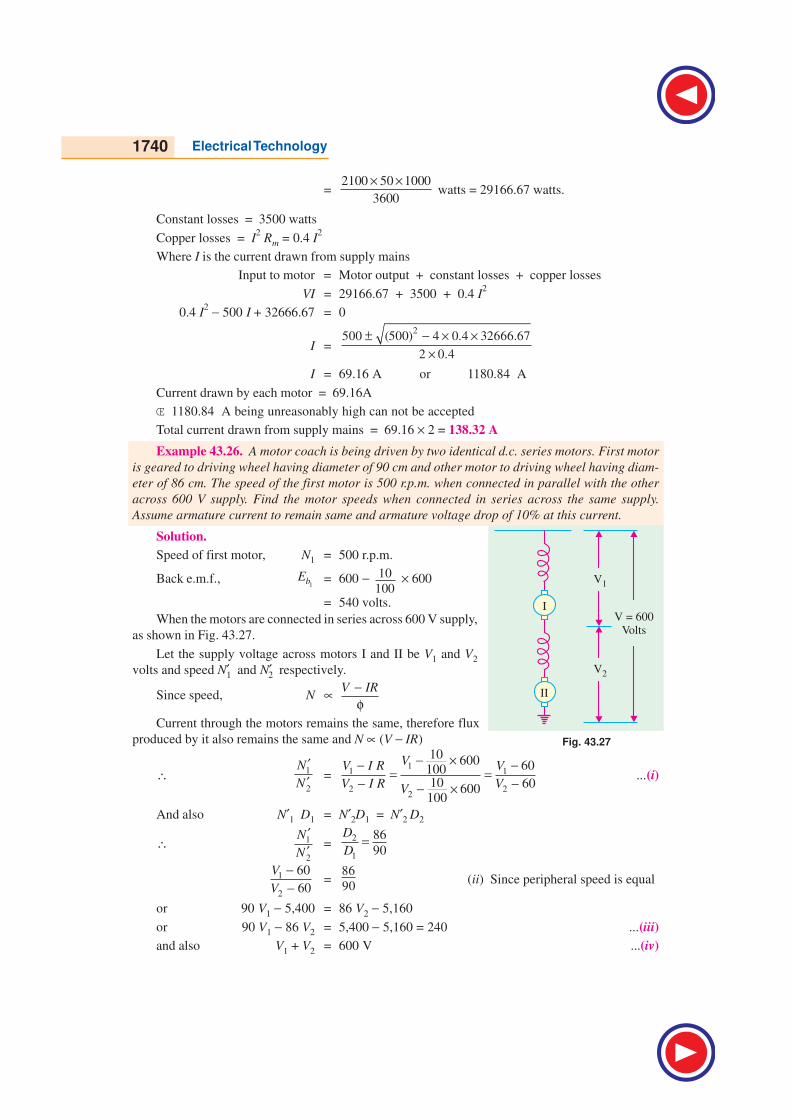
1740 Electrical Technology
= 2100 50 1000
3600
× × watts = 29166.67 watts.
Constant losses = 3500 watts
Copper losses = I2 Rm = 0.4 I
2
Where I is the current drawn from supply mains
Input to motor = Motor output + constant losses + copper losses
VI = 29166.67 + 3500 + 0.4 I2
0.4 I2 − 500 I + 32666.67 = 0
I =
2500 (500) 4 0.4 32666.67
2 0.4
± − × ××
I = 69.16 A or 1180.84 A
Current drawn by each motor = 69.16A
Π1180.84 A being unreasonably high can not be accepted
Total current drawn from supply mains = 69.16 × 2 = 138.32 A
Example 43.26. A motor coach is being driven by two identical d.c. series motors. First motor
is geared to driving wheel having diameter of 90 cm and other motor to driving wheel having diam-
eter of 86 cm. The speed of the first motor is 500 r.p.m. when connected in parallel with the other
across 600 V supply. Find the motor speeds when connected in series across the same supply.
Assume armature current to remain same and armature voltage drop of 10% at this current.
Solution.
Speed of first motor, N1 = 500 r.p.m.
Back e.m.f.,1bE = 600 − 10
100 × 600
= 540 volts.
When the motors are connected in series across 600 V supply,
as shown in Fig. 43.27.
Let the supply voltage across motors I and II be V1 and V2
volts and speed N′1 and N′2 respectively.
Since speed, N ∝ V IR−φ
Current through the motors remains the same, therefore flux
produced by it also remains the same and N ∝ (V − IR)
∴ 1
2
N
N
′′ =
11 1
2 22
10 600 6010010 60600100
VV I R V
V I R VV
− ×− −= =
− −− ×...(i)
And also N′1 D1 = N′2D1 = N′2 D2
∴ 1
2
N
N
′′
=2
1
86
90
D
D=
1
2
60
60
V
V
−−
=86
90(ii) Since peripheral speed is equal
or 90 V1 − 5,400 = 86 V2 − 5,160
or 90 V1 − 86 V2 = 5,400 − 5,160 = 240 ...(iii)
and also V1 + V2 = 600 V ...(iv)
Fig. 43.27
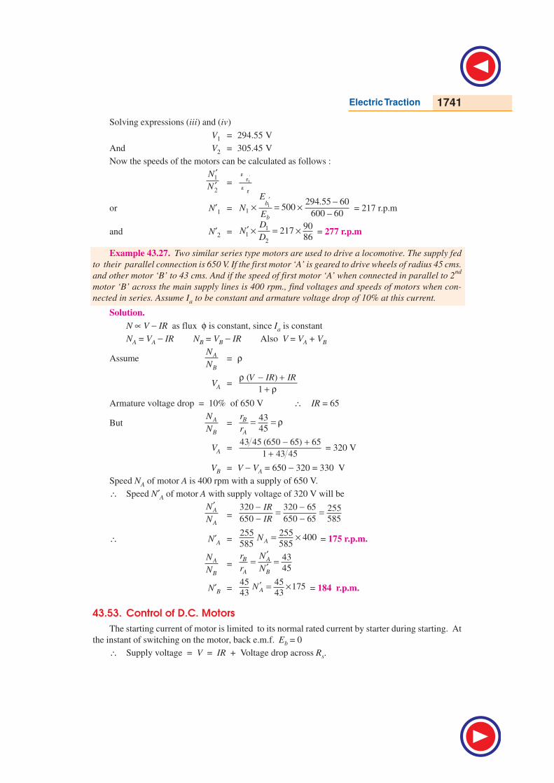
Electric Traction 1741
Solving expressions (iii) and (iv)
V1 = 294.55 V
And V2 = 305.45 V
Now the speeds of the motors can be calculated as follows :
1
2
N
N
′′ = 1b
b
E
E
′
or N′1 = 1
1
294.55 60500
600 60
b
b
E
NE
′ −× = ×−
= 217 r.p.m
and N′2 =1
12
90217
86
DN
D′ × = × = 277 r.p.m
Example 43.27. Two similar series type motors are used to drive a locomotive. The supply fed
to their parallel connection is 650 V. If the first motor ‘A’ is geared to drive wheels of radius 45 cms.
and other motor ‘B’ to 43 cms. And if the speed of first motor ‘A’ when connected in parallel to 2nd
motor ‘B’ across the main supply lines is 400 rpm., find voltages and speeds of motors when con-
nected in series. Assume Ia to be constant and armature voltage drop of 10% at this current.
Solution.
N ∝ V − IR as flux φ is constant, since Ia is constant
NA = VA − IR NB = VB − IR Also V = VA + VB
AssumeA
B
N
N= ρ
VA =( )
1
V IR IRρ − ++ ρ
Armature voltage drop = 10% of 650 V ∴ IR = 65
ButA
B
N
N=
43
45B
A
r
r= = ρ
VA =43 45 (650 65) 65
1 43 45
− ++
= 320 V
VB = V − VA = 650 − 320 = 330 V
Speed NA of motor A is 400 rpm with a supply of 650 V.
∴ Speed N′A of motor A with supply voltage of 320 V will be
A
A
N
N
′=
320 320 65 255
650 650 65 585
IR
IR
− −= =− −
∴ N′A =255 255
400585 585AN = × = 175 r.p.m.
A
B
N
N=
43
45B A
A B
r N
r N
′= =
′
N′B =45 45
17543 43AN ′ = × = 184 r.p.m.
43.53. Control of D.C. Motors
The starting current of motor is limited to its normal rated current by starter during starting. At
the instant of switching on the motor, back e.m.f. Eb = 0
∴ Supply voltage = V = IR + Voltage drop across Rs.
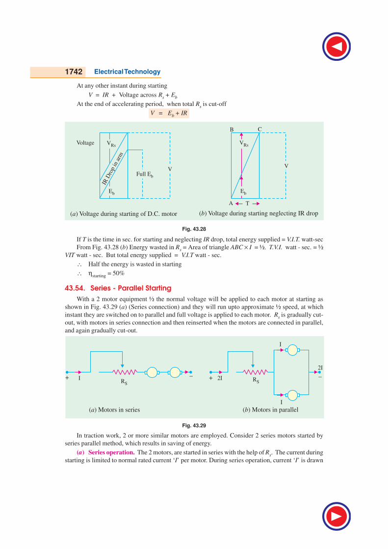
1742 Electrical Technology
At any other instant during starting
V = IR + Voltage across Rs + Eb
At the end of accelerating period, when total Rs is cut-off
V = Eb + IR
Fig. 43.28
If T is the time in sec. for starting and neglecting IR drop, total energy supplied = V.I.T. watt-sec
From Fig. 43.28 (b) Energy wasted in Rs = Area of triangle ABC × I = ½. T.V.I. watt - sec. = ½
VIT watt - sec. But total energy supplied = V.I.T watt - sec.
∴ Half the energy is wasted in starting
∴ ηstarting = 50%
43.54. Series - Parallel Starting
With a 2 motor equipment ½ the normal voltage will be applied to each motor at starting as
shown in Fig. 43.29 (a) (Series connection) and they will run upto approximate ½ speed, at which
instant they are switched on to parallel and full voltage is applied to each motor. Rs is gradually cut-
out, with motors in series connection and then reinserted when the motors are connected in parallel,
and again gradually cut-out.
Fig. 43.29
In traction work, 2 or more similar motors are employed. Consider 2 series motors started by
series parallel method, which results in saving of energy.
(a) Series operation. The 2 motors, are started in series with the help of Rs. The current during
starting is limited to normal rated current ‘I’ per motor. During series operation, current ‘I’ is drawn

Electric Traction 1743
from supply. At the instant of starting OA = AB = IR drop in each motor. OK = Supply voltage ‘V’.
The back e.m.fs. of 2 motors jointly develop along OM as shown in Fig. 43.30 (a). At point. E,
supply voltage V = Back e.m.fs of 2 motors + IR drops of 2 motor. Any point on the line BC represents
the sum of Back e.m.fs. of 2 motors + IR drops of 2 motors + Voltage across resistance Rs of 2 motors
OE = time taken for series running.
At pt ‘E’ at the end of series running period, each motor has developed a back e.m.f.
=2
V − IR
EL = ED − LD
(b) Parallel operation. The motors are switched on in parallel at the instant ‘E’, with Rs
reinserted as shown in Fig. 43.29 (b). Current drawn is 2I from supply. Back e.m.f. across each
motor = EL. So the back e.m.f. now develops along LG. At point ‘H’ when the motors are in full
parallel, (Rs = 0 and both the motors are running at rated speed)
Supply voltage = V = HF = HG + GF
= Normal Back e.m.f. of each motor + IR drop in each motor.
43.55. To find ts, tp and η η η η η of starting
The values of time ts during which the motors remain in series and tp during which they are in
parallel can be determined from Fig. 43.30 (a), (c). From Fig. 43.30 (a), triangles OLE and OGH are
similar
∴OE
OH= 2s
V IRt DE DLLE
GH T FH FG V IR
−−∴ = =− −
∴ ts =21
2
V IRT
V IR
− −
tp
= T − ts =
21
2
V IRT T
V IR
− − −
tp
=21
12
V IRT T
V IR
− − −
(a) Voltage built-up in series-parallel starting (b) Variation of current in series-parallel starting
Fig. 43.30
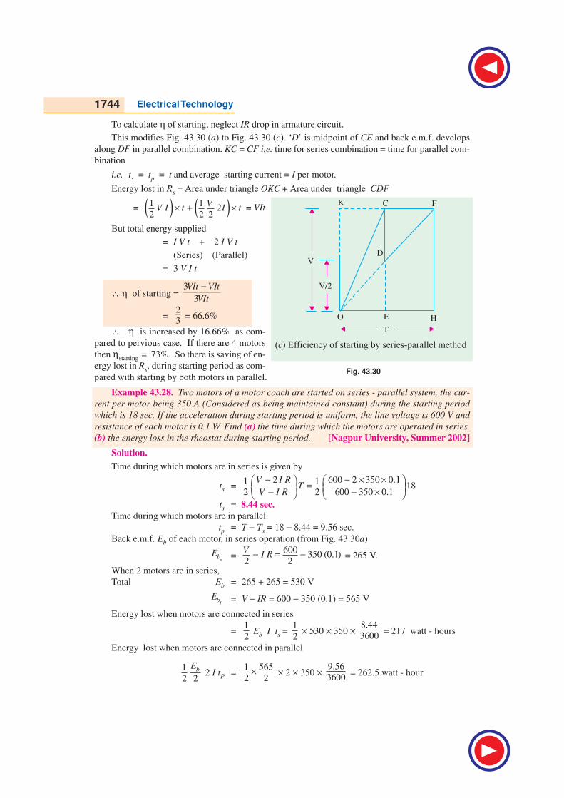
1744 Electrical Technology
To calculate η of starting, neglect IR drop in armature circuit.
This modifies Fig. 43.30 (a) to Fig. 43.30 (c). ‘D’ is midpoint of CE and back e.m.f. develops
along DF in parallel combination. KC = CF i.e. time for series combination = time for parallel com-
bination
i.e. ts = tp = t and average starting current = I per motor.
Energy lost in Rs = Area under triangle OKC + Area under triangle CDF
= ( ) ( )1 12
2 2 2
VV I t I t× + × = VIt
But total energy supplied
= I V t + 2 I V t
(Series) (Parallel)
= 3 V I t
∴ η of starting = 3
3
VIt VIt
VIt
−
=2
3 = 66.6%
∴ η is increased by 16.66% as com-
pared to pervious case. If there are 4 motors
then ηstarting = 73%. So there is saving of en-
ergy lost in Rs, during starting period as com-
pared with starting by both motors in parallel.
Example 43.28. Two motors of a motor coach are started on series - parallel system, the cur-
rent per motor being 350 A (Considered as being maintained constant) during the starting period
which is 18 sec. If the acceleration during starting period is uniform, the line voltage is 600 V and
resistance of each motor is 0.1 W. Find (a) the time during which the motors are operated in series.
(b) the energy loss in the rheostat during starting period. [Nagpur University, Summer 2002]
Solution.
Time during which motors are in series is given by
ts = 2 600 2 350 0.11 1
182 2 600 350 0.1
V I RT
V I R
− − × × = − − × ts = 8.44 sec.
Time during which motors are in parallel.
tp = T − Ts = 18 − 8.44 = 9.56 sec.
Back e.m.f. Eb of each motor, in series operation (from Fig. 43.30a)
sbE =
600350 (0.1)
2 2
VI R− = − = 265 V.
When 2 motors are in series,
Total Eb = 265 + 265 = 530 V
PbE = V − IR = 600 − 350 (0.1) = 565 V
Energy lost when motors are connected in series
=1
2 Eb I ts =
1
2 × 530 × 350 ×
8.44
3600 = 217 watt - hours
Energy lost when motors are connected in parallel
1
2 2bE
2 I tP =1 565
2 2× × 2 × 350 ×
9.56
3600 = 262.5 watt - hour
Fig. 43.30
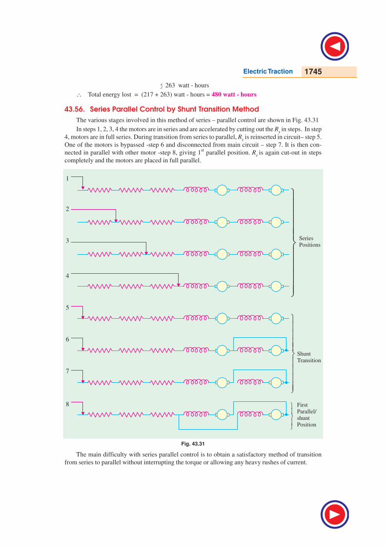
Electric Traction 1745
j 263 watt - hours
∴ Total energy lost = (217 + 263) watt - hours = 480 watt - hours
43.56. Series Parallel Control by Shunt Transition Method
The various stages involved in this method of series – parallel control are shown in Fig. 43.31
In steps 1, 2, 3, 4 the motors are in series and are accelerated by cutting out the Rs in steps. In step
4, motors are in full series. During transition from series to parallel, Rs is reinserted in circuit– step 5.
One of the motors is bypassed -step 6 and disconnected from main circuit – step 7. It is then con-
nected in parallel with other motor -step 8, giving 1st parallel position. Rs is again cut-out in steps
completely and the motors are placed in full parallel.
Fig. 43.31
The main difficulty with series parallel control is to obtain a satisfactory method of transition
from series to parallel without interrupting the torque or allowing any heavy rushes of current.
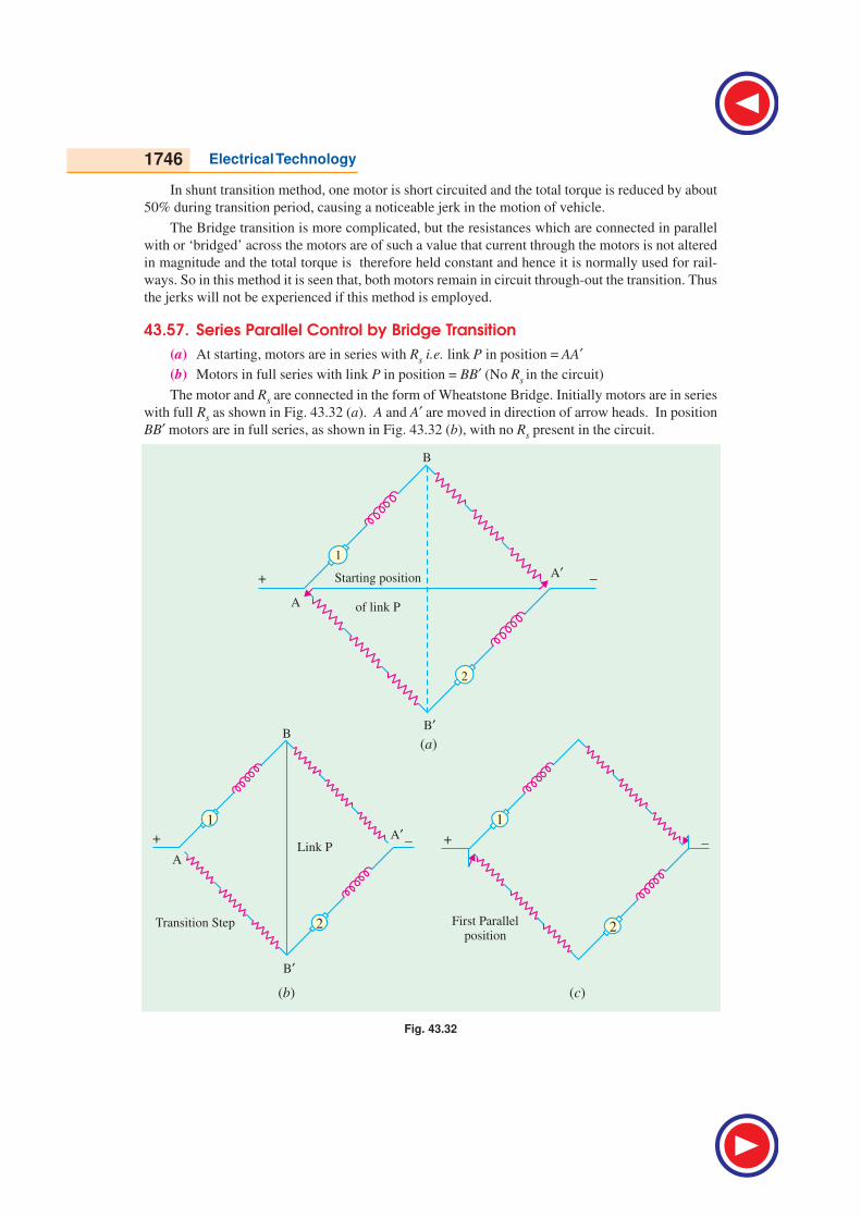
1746 Electrical Technology
In shunt transition method, one motor is short circuited and the total torque is reduced by about
50% during transition period, causing a noticeable jerk in the motion of vehicle.
The Bridge transition is more complicated, but the resistances which are connected in parallel
with or ‘bridged’ across the motors are of such a value that current through the motors is not altered
in magnitude and the total torque is therefore held constant and hence it is normally used for rail-
ways. So in this method it is seen that, both motors remain in circuit through-out the transition. Thus
the jerks will not be experienced if this method is employed.
43.57. Series Parallel Control by Bridge Transition
(a) At starting, motors are in series with Rs i.e. link P in position = AA′(b) Motors in full series with link P in position = BB′ (No Rs in the circuit)
The motor and Rs are connected in the form of Wheatstone Bridge. Initially motors are in series
with full Rs as shown in Fig. 43.32 (a). A and A′ are moved in direction of arrow heads. In position
BB′ motors are in full series, as shown in Fig. 43.32 (b), with no Rs present in the circuit.
Fig. 43.32
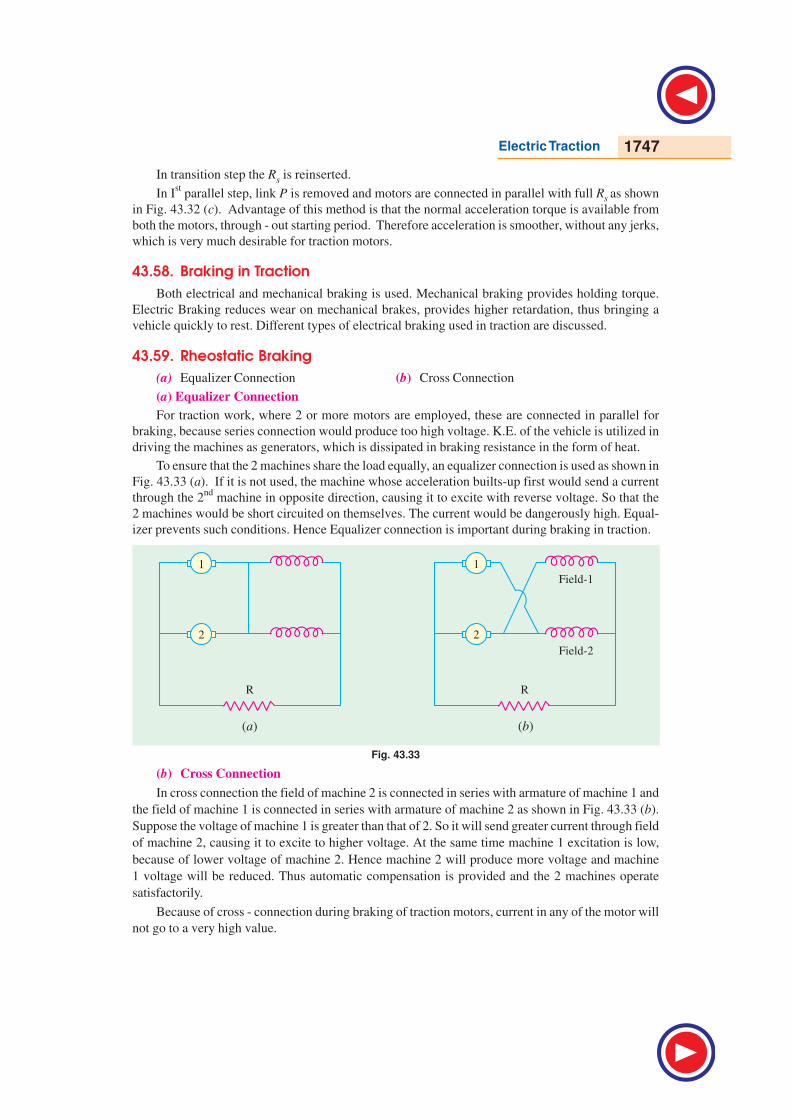
Electric Traction 1747
In transition step the Rs is reinserted.
In Ist parallel step, link P is removed and motors are connected in parallel with full Rs as shown
in Fig. 43.32 (c). Advantage of this method is that the normal acceleration torque is available from
both the motors, through - out starting period. Therefore acceleration is smoother, without any jerks,
which is very much desirable for traction motors.
43.58. Braking in Traction
Both electrical and mechanical braking is used. Mechanical braking provides holding torque.
Electric Braking reduces wear on mechanical brakes, provides higher retardation, thus bringing a
vehicle quickly to rest. Different types of electrical braking used in traction are discussed.
43.59. Rheostatic Braking
(a) Equalizer Connection (b) Cross Connection
(a) Equalizer Connection
For traction work, where 2 or more motors are employed, these are connected in parallel for
braking, because series connection would produce too high voltage. K.E. of the vehicle is utilized in
driving the machines as generators, which is dissipated in braking resistance in the form of heat.
To ensure that the 2 machines share the load equally, an equalizer connection is used as shown in
Fig. 43.33 (a). If it is not used, the machine whose acceleration builts-up first would send a current
through the 2nd
machine in opposite direction, causing it to excite with reverse voltage. So that the
2 machines would be short circuited on themselves. The current would be dangerously high. Equal-
izer prevents such conditions. Hence Equalizer connection is important during braking in traction.
Fig. 43.33
(b) Cross Connection
In cross connection the field of machine 2 is connected in series with armature of machine 1 and
the field of machine 1 is connected in series with armature of machine 2 as shown in Fig. 43.33 (b).
Suppose the voltage of machine 1 is greater than that of 2. So it will send greater current through field
of machine 2, causing it to excite to higher voltage. At the same time machine 1 excitation is low,
because of lower voltage of machine 2. Hence machine 2 will produce more voltage and machine
1 voltage will be reduced. Thus automatic compensation is provided and the 2 machines operate
satisfactorily.
Because of cross - connection during braking of traction motors, current in any of the motor will
not go to a very high value.
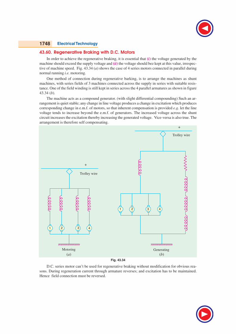
1748 Electrical Technology
43.60. Regenerative Braking with D.C. Motors
In order to achieve the regenerative braking, it is essential that (i) the voltage generated by the
machine should exceed the supply voltage and (ii) the voltage should bez kept at this value, irrespec-
tive of machine speed. Fig. 43.34 (a) shows the case of 4 series motors connected in parallel during
normal running i.e. motoring.
One method of connection during regenerative barking, is to arrange the machines as shunt
machines, with series fields of 3 machines connected across the supply in series with suitable resis-
tance. One of the field winding is still kept in series across the 4 parallel armatures as shown in figure
43.34 (b).
The machine acts as a compound generator. (with slight differential compounding) Such an ar-
rangement is quiet stable; any change in line voltage produces a change in excitation which produces
corresponding change in e.m.f. of motors, so that inherent compensation is provided e.g. let the line
voltage tends to increase beyond the e.m.f. of generators. The increased voltage across the shunt
circuit increases the excitation thereby increasing the generated voltage. Vice-versa is also true. The
arrangement is therefore self compensating.
Fig. 43.34
D.C. series motor can’t be used for regenerative braking without modification for obvious rea-
sons. During regeneration current through armature reverses; and excitation has to be maintained.
Hence field connection must be reversed.
Electric Traction 1749
Example 43.29. Two 750 V D.C. series motors each having a resistance of 0.1 W are started on
series - parallel system. Mean current through - out the starting period is 300 A. Starting period is
15 sec. and train speed at the end of this period is 25 km/hr. Calculate
(i) Rheostatic losses during series and parallel combination of motors
(ii) Energy lost in motor
(iii) Motor output
(iv) Starting η(v) Train speed at which transition from series to parallel must be made.
[Nagpur University, Summer 2000]
Solution.
(i) ts =21
2
V I RT
V I R
− −
ts =750 2(300) 0.11
152 750 (300) 0.1
− −
= 7.1875 rec.
∴ tp = T − ts = 7.8125 sec.
Energy lost in Rheostat = 1
2
sbE I ts + 1
2 2
pbE
2 I.tp
=1 1
2 . [[ ] / 2] 2 .2 2 2s p
VIR I t V IR I t
× − + −
=750 300 (0.1)1 750 1
2 300 (0.1) 300 7.1875 2(300) 7.18252 2 2 2
− × − × + × × = 743906.25 + 843750
= 1587656.25 watt – sec.
=1587656.25
3600 = 441.00 watt - hrs.
(ii) Total Energy supplied = V.I. ts + 2 I . V . tp
= 750 × 300 (7.1875) + 2 (300) 750 (7.8125)
= 1617187.5 + 3515625
= 5132812.5 watt-sec = 1425.7812 watt – hrs.
Energy lost in 2 Motors = (Ia
2 × Ra) × 2 × 15
= (3002 × 0.1) × 2 × 15 = 270000 watt - sec. = 75 watt - hrs.
(iii) Motor O/P = Total Energy supplied − Energy lost in Rheostat − Energy lost in armature
= 1425.7812 − 441 − 75
= 909.7812 watt – hrs.
(iv) η starting =Total Energy Supplied Energy lost in Rheostat
Total Energy Supplied
−
=1425.7812 441.00
1001425.7812
− ×
= 69.0605%
(v) Acceleration is uniform during starting period of 15 sec. Therefore speed after which series
to parallel transition must be made is given as –
=Speed after starting period
Total starting period st×
1750 Electrical Technology
=25
7.187515
×
= 11.9791 km/hr.
Example 43.30. Two 600-V motors each having a resistance of 0.1Ω are started on the series-
parallel system, the mean current per motor throughtout the starting period being 300A. The starting
period is 20 seconds and the train speed at the end of this period is 30 km per hour. Calculate (i) the
rheostatic losses (in kwh) during (a) the series and (b) the parallel combinations of motors (ii) the
train speed at which transition from series to parallel must be made.
Solution.
Number of motors operating = 2
Line voltage, V = 600 volts
Current per motor, I = 300 amperes
Starting period, Ts = 20 seconds
Motor resistance, R = 0.1 ΩMaximum speed, Vm = 30 kmph.
Back e.m.f. of each motor in full series position,
sbE =
600
2 2
VIR− = − 300 × 0.1 = 270 volts.
Back e.m.f. of each motor in full parallel position,
pbE = V − IR − 300 × 0.1 = 570 volts
Assuming smooth acceleration, back e.m.f. will be built up at constant rate.
Since motors take 20 seconds to build up 570 volts, therefore time taken to build up 270 volts
e.m.f. will be :
Tseries = 20 × 270
570 = 9.4737 seconds
Tparallel = 20 − 9.4737 = 10.5263 seconds
(i) (a) Voltage drop in the starting rheostat in series combination at the starting instant
= V − 2IR = 600 − 2 × 300 × 0.1 = 540 volts,
which reduces to zero in full series position
Energy dissipated in starting resistance during series combination
= series( 2 ) 0 540 0 9.4737
3002 3600 2 3600
TV I RI
− + +× × = × ×
= 213.1579 watt - hours
(b) Voltage drop across the starting resistance in first parallel position is equal to V/2 i.e.
300 volts which gradually reduces to zero.
Energy dissipated in starting resistance during parallel combination
= parallel
6000 0
10.52632 221 2 3002 3600 2 3600
VT+ +
× × = × × ×
= 263.1579 watt – hours
(ii) Acceleration, α =Maximum speed 30
Starting period 20m
s
V
T= = = 1.5 kmphps.
Speed at the end of series period = α Tseries = 1.5 × 9.4737 = 14.21 km/hour
Example 43.31. Two d.c. series motors of a motor coach have resistance of 0.1 W each. These
motors draw a current of 500 A from 600 V mains during series – parallel starting period of
25 seconds. If the acceleration during starting period remains uniform, determine:
Electric Traction 1751
(i) time during which the motors operate in (a) series (b) parallel.
(ii) the speed at which the series connections are to be changed if the speed just after starting
period is 80 kmph.
Solution.
Number of motors operating = 2
Line voltage, V = 600 V
Current per motor, I = 500 A
Motor resistance, R = 0.1 ΩMaximum speed, Vm = 80 kmph.
Back e.m.f. of each motor in full series position.
sbE =
600
2 2
VI R− = − 500 × 0.1 = 250 V
Back e.m.f. each motor in full parallel operation,
pbE = V − IR = 600 − 500 × 0.1 = 550 V
Since motors take 25 seconds to build up 550 V, therefore, time taken to build up 250 V, will be:
(assuming smooth acceleration and building up of e.m.f. at constant rate.)
(i) Period of series operation, Tseries = 25 × 255
550 = 11.3636 seconds
Period of parallel operation,Tparallel = T − Tse = 25 − 11.3636 = 13.6363 seconds
(iii) Speed at which the series connections are to be changed
= α Tseries = mV
T . Tseries =
80
25 × 11.3636 = 36.3636 kmph
Example 43.32. The following figures refer to the speed-current and torque – current charac-
teristics of a 600 V d.c. series traction motor.
Current, amperes : 50 100 150 200 250
Speed, kmph : 73.6 48 41.1 37.3 35.2
Torque, N-m : 150 525 930 1,335 1,750
Determine the braking torque at a speed of 48 kmph when operating as self excited d.c. genera-
tor. Assume resistance of motor and braking rheostat to be 0.6Ω and 3.0 Ω respectively.
Solution.
As motor :
Terminal voltage, V = 600 volts.
The motor current at a speed of 48 kmph (from speed-current characteristic curve),
I = 100 A
Back e.m.f. developed by the motor, Eb = V − IRm = 600 – 100 × 0.6 = 540 V
As Generator:
At the instant of applying rheostatic braking at speed of 48 kmph, the terminal voltage of
machine will be equal to e.m.f. developed by the machine i.e. 540 volts.
Total resistance in the circuit = Rm + Rrheostat = 0.6 + 3 = 3.6 Ω
Current delivered by the machine, I = 540
3.6 = 150 amps
The braking torque (the torque corresponding to 150 amperes from torque-current curve)
= 930 N-m
1752 Electrical Technology
Tutorial Problem No. 43.1
1. A train weighs 500 tonnes. What is its mass in (i) tonnes and (ii) kilograms.
[(i) 500 t (ii) 500,000 kg]
2. A train has a mass of 200 tonnes. What is its weight in (i) newtons and (ii) kg-wt (iii) tonnes-wt.
[(i) 19.6 ××××× 105 N (ii) 200,000 kg. wt (iii) 200 t-wt )]
3. A train has a speed of 100 km/h. What is its value in m/s ? [27.78 m/s]
4. A certain express train has an acceleration of 3.6 km/h/s. What is its value in m/s2 ? [1.0 m/s
2]
5. If there is an ascending gradient of 15 m in a track length of 1 km, what is the value of percentage
gradient ? [1.5%]
6. A train runs at an average speed of 45 km per hour between stations 2.5 km apart. The train acceler-
ates at 2 km/h/s and retards at 3 km/h/s. Find its maximum speed assuming a trapezoidal speed/time
curve. Calculate also the distance travelled by it before the brakes are applied.
[50.263 km/h, 2.383 km] (Elect. Traction and Utilization B.H.U. )
7. The schedule speed with a 200 tonne train on an electric railway with stations 777 metres apart is
27.3 km/h and the maximum speed is 20 percent higher than the average running speed. The braking
rate is 3.22 km/h/s and the duration of stops is 20 seconds. Find the acceleration required. Assume a
simplified speed-time curve with free running at the maximum speed.
[2.73 km/h/s] (Traction and Utilization of Elect. Power, Agra Univ.)
8. A suburban electric train has a maximum speed of 65 km/h.. The schedule speed including a station
stop of 30 seconds is 43.5 km/h. If the acceleration is 1.3 km/h/s, find the value of retardation when
the average distance between stops is 3 km.
[βββββ = 1.21 km/h/s] (Utilization of Elect. Power and Traction, Gorakhpur Univ.,)
9. An electric train is accelerated uniformly from rest to a speed of 40 km/h, the period of acceleration
being 20 seconds. If it coasts for 60 seconds against a constant resistance of 50 N/t and is brought to
rest in a further period of 10 seconds by braking, determine :
(i) the acceleration (ii) the coasting retardation (iii) the braking retardation (iv) distance travelled
and (v) schedule speed with station stops of 10 seconds duration.
Allow 10 percent for rotational inertia. (Elect. Traction, Punjab Univ.)
[ααααα = 2 km/h/s, βββββc = 0.1636 km/h/s, βββββ = 3 km/h/s., D = 0.736 km., V = 27.5 km/h]
10. The speed-time curve of an electric train on a uniform rising gradient of 1 in 100 comprises :
(i) uniform acceleration from rest at 2 km/h/s/ for 30 seconds.
(ii) coasting with power off for 70 seconds.
(iii) braking at 3 km/h/s to a standstill.
The weight of the train is 250 tonnes, the train resistance on level track being 49 N/tonne and allow-
ance for rotary inertia 1%.
Calculate the maximum power developed by traction motors and total distance travelled by the train.
Assume transmission efficiency as 97%.
[3,3258 kW, 1.12 km] (Traction and Utilization of Elect. Power, Agra Univ.)
11. A 400-tonne goods train is to be hauled by a locomotive up a gradient of 2% with an acceleration of
1 km/h/s. Co-efficient of adhesion is 20%, track resistance 40 N/tonne and effective rotating masses
10% of the dead weight. Find the weight of the locomotive and number of axles if the axle load is not
increased beyond 22 tonnes.[152.6 tonnes, 7] (Traction and Utilization of Elect. Power, Agra Univ.)
12. A 500-tonne goods train is to be hauled by a locomotive up a gradient of 20% with an acceleration of
1.2 km/h/s. Co-efficient of adhesion is 25%, track resistance 40 N/ tonne and effective rotating
masses 10% of dead weight. Find the weight of the locomotive and number of axles if axle load is not
to exceed 20 tonnes. [160 tonnes, 8] (Utilization of Elect. Power, A.M.I.E. Winter)
Electric Traction 1753
13. Determine the maximum adhesive weight of a loco required to start a 2340 tonne weight (inclusive
of loco) on 1 : 150 gradient and accelerate it at 0.1 km/h/s. Assume co-efficient of adhesion as 0.25,
train resistance 39.2 N/tonne and rotary inertia as 8%. [128.5 tonnes]
(Elect. Traction, A.M.I.E., May )
14. Ore carrying trains weighing 5000 tonne each are to be hauled down a gradient of 1 in 60 at a
maximum speed of 40 km/h and started on a level track at an acceleration of 0.1 m/s2. How many
locomotives, each weighing 75 tonne, will have to be employed ?
Train resistance during starting = 29.4 N/tonne
Train resistance at 40 km/h = 56.1 kg/tonne
Co-efficient of adhesion = 1/3 ; Rotational inertia = 1/10
[3 Loco] (Engg. Service Examination U.P.S.C.)
15. A locomotive accelerates a 400-tonne train up a gradient of 1 in 100 at 0.8 km/h/s. Assuming the
coefficient of adhesion to be 0.25, determine the minimum adhesive weight of the locomotive.
Assume train resistance of 60 N/tonne and allow 10% for the effect of rotational inertia.
[65.7 t] (Elect. Traction and Utilization, Nagpur Univ.)
16. Calculate the specific energy consumption if a maximum speed of 12.20 metres/sec and for a given
run of 1525 m an acceleration of 0.366 m/s2 are desired. Train resistance during acceleration is 52.6
N/1000 kg and during coasting is 6.12 N/1000 kg, 10% being allowable for rotational inertia. The
efficiency of the equipment during the acceleration period is 50%. Assume a quadrilateral speed-
time curve. [3.38 Wh/kg-m] (Util. of Elect. Power, A.M.I.E. Sec. B)
17. An electric locomotive of 100 tonne can just accelerate a train of 500 tonne (trailing weight) with an
acceleration of 1 km/h/s on an upgradient of 1/1000. Tractive resistance of the track is 45 N per tonne
and the rotational inertia is 10%. If this locomotive is helpled by another locomotive of 120 tonnes,
find, (i) the trailing weight that can be hauled up the same gradient under the same conditions and
(ii) the maximum gradient, the trailing weight hauled remaining unchanged.
Assume adhesive weight expressed as percentage of total dead weight to be the same for both the
locomotive. [(i) 1120 t (ii) 3.15%] (Util. of Elect. Power, A.M.I.E. Sec. B.)
18. An electric train has quadrilateral speed-time curve as follows :
(i) uniform acceleration from rest at 2 km/h/s for 30 sec,
(ii) coasting for 50 sec.
(iii) uniform braking to rest for 20 seconds.
If the train is moving uniform upgradient of a 10/1000, train resistance is 40 N/tonne, rotational
inertia effect 10% of dead weight and duration of stop 30 seconds, find the schedule speed.
[28.4 km/h] (Util. of Elect. Power, A.M.I.E. Sec. B.)
19. The schedule speed with a 200 tonne train on an electric railway with stations 777 metres apart is
27.3 km/h and the maximum speed is 20% higher than the average running speed. The braking rate
is 3.22 km/h/s and the duration of stops is 20 seconds. Find the acceleration required. Assume a
simplified speed-time curve with the free running at the maximum speed.
[2.73 km/h/s] (Traction & Util. of Elect. Power, Agra Univ.)
20. An electric train has an average speed of 42 km/h on a level track between stops 1,400 metre apart. It
is accelerated at 1.7 km/h/s and is braked at 3.3 km/h/s. Draw the speed-time curve for the run.
Estimate the sp. energy consumption. Assume tractive resistance as 50 N/t and allow 10% for rota-
tional inertia. [39.48 Wh/t-km] (Util. of Elect. Power, A.M.I.E. Sec. B.)
21. An electric train weighing 200 tonne has eight motors geared to driving wheels, each wheel is 90 cm
diameter. Determine the torque developed by each motor to accelerate the train to a speed of 48 km/
h in 30 seconds up a gradient of 1 in 200. The tractive resistance is 50 N/t, the effect of rotational
inertia is 10% of the train weight, the gear ratio is 4 to 1 and gearing efficiency is 80%.
[2,067 N-m] (Traction & Util. of Elect. Power, Agra Univ.)
1754 Electrical Technology
22. An electric train accelerates uniformly from rest to a speed of 48 km/h in 24 seconds. It then coasts
for 69 seconds against a constant resistance of 58 N/t and is braked to rest at 3.3 km/h/s in 11
seconds.
Calculate (i) the acceleration (ii) coasting retardation and (iii) the schedule speed, if the station stops
are of 20 seconds duration. What would be the effect on schedule speed of reducing the station stops
to 15 second duration, other conditions remaining the same? Allow 10% for the rotational inertia.
[(i) 2 km/h/s (ii) 0.19 km/h/s (iii) 30.25 km/h]
(Util. of Elect. Power, A.M.I.E. Sec. B.)
23. An electric train accelerates uniformly from rest to a speed of 50 km/h in 25 seconds. It then coasts
for 1 minute 10 seconds against a constant resistance of 70 N/t and is braked to rest at 4 km/h/s in 10
seconds. Calculate the schedule speed, if the station stops are of 15 second duration.
[31.125 km/h] (Util. of Elect. Power, A.M.I.E. Sec. B)
24. An electric train has a quadrilatural speed-time curve as follows :
(i) uniform acceleration from rest at 2.5 km/h/s for 25 second
(ii) coasting for 50 second (iii) duration of braking 25 second.
If the train is moving along a uniform upgradient of 1 in 100 with a tractive resistance of 45 N/t,
rotational inertia 10% of dead weight, duration of stops at stations 20 second and overall efficiency
of transmission gear and motor 80%, calculate the schedule speed and specific energy consumption
of run. [69 km/h, 26.61 Wh/t-km] (Util. of Elect. Power, A.M.I.E. Sec. B)
25. An ore-carrying train weighing 5000 tonne is to be hauled down a gradient of 1 in 50 at a maximum
speed of 30 km/h and started on a level track at an acceleration of 0.08 m/s2. How many locomotives,
each weighing 75 tonne, will have to be employed ?
Train resistance during starting =3 kg/t
Train resistance at 30 km/h = 5 kg/t
Co-efficient of adhesion = 0.3, Rotational inertia = 10%.
[4 loco] (Util. of Elect. Power, A.M.I.E. Sec. B.)
26. A train with an electric locomotive weighing 300 tonne is is to be accelerated up a gradient of 1 in 33
at an acceleration of 1 km/h/s. If the train resistance, co-efficient of adhesion and effect of rotational
inertia are 80 N/t, 0.25 and 12.5% of the dead weight respectively, determine the minimum adhesive
weight of the locomotive. [88 t] (Util. of Elect. Power, A.M.I.E. Sec. B.)
27. A train weighing 400 tonne has speed reduced by regenerative braking from 40 to 20 km/h over a
distance of 2 km at a down gradient of 20%. Calculate the electrical energy and average power
returned to the line. Tractive resistance is 40 N/t and allow rotational inertia of 10% and efficiency of
conversion 75%. [324 kW/h, 4860 kW] (Util. & Traction Power, Agra Univ.)
28. A 250-tonne motor coach having 4 motors, each developing 5,000 N-m torque acceleration, starts
from rest. If upgradient is 25 in 1000, gear ratio 5, gear transmission efficiency 88%, wheel radius
44 cm, train resistance 50 N/t addition of rotational inertia 10%, calculate the time taken to reach a
speed of 45 km/h.
If the supply voltage were 1500 V d.c. and efficiency of motor is 83.4%, determine the current drawn
per motor during notching period. [27.25 s, 500 A] (Util. of Elect. Power, A.M.I.E. Sec. B.)
29. An electric train weighing 100 tonne has a rotational inertia of 10%. This train while running be-
tween two stations which are 2.5 km apart has an average speed of 50 km/h. The acceleration and
retardation during braking are respectively 1 km/h/s and 2 km/h/s. The percentage gradient between
these two stations is 1% and the train is to move up the incline. The track resistance is 40 N/t. If the
combined efficiency of the electric train is 60%, determine (i) maximum power at driving axle (ii)
total energy consumption and (iii) specific energy consumption. Assume that journey estimation is
being made in simplified trapezoidal speed-time curve.
[(i) 875 kW (ii) 23.65 kW/h (iii) 94.6 Wh/t-km] (Util. of Elect. Power, A.M.I.E. Sec. B.)
Electric Traction 1755
30. A 500-tonne goods train is to be hauled by a locomotive up a gradient of 1 in 40 with an acceleration
of 1.5 km/h/s. Determine the weight of the locomotive and number of axles, if axle load is not to
exceed 24 tonne. Co-efficient of adhesion is 0.31, track resistance 45 N/t and effective rotating
masses 10% of dead weight. [7] (Util. of Elect. Power, A.M.I.E. Sec. B.)
31. Two d.c. series motors of a motor coach have resistance of 0.1 W each. These motors draw a current
of 500 A from 600V mains during series-parallel starting period of 20 seconds. If the acceleration
during starting period remains uniform, determine :
(i) time during which motor operates in (a) series, (b) parallel
(ii) the speed at which the series connections are to be changed if the speed just after starting period
is 70 km/h.
[(i) 9.098, 10.971 Sec. (ii) 31.82 km/h] (Utili. of Elect. Power and Traction, Agra Univ.)
32. Explain how series motors are ideally suited for traction service.
(Nagpur University, Summer 2004)
33. Explain any one method for regenerative braking of D.C. motor for traction.
(Nagpur University, Summer 2004)
34. Discuss the effect of unequal wheel diameters on the parallel operation of traction motors.
(Nagpur University, Summer 2004)
35. Explain the various modes of operation in traction services with neat speed-time curve.
(Nagpur University, Summer 2004)
36. A 100 tonne motor coach is driven by 4 motors, each developing a torque of 5000 N-m during
acceleration. If up-gradient is 50 in 1000, gear ratio a = 0.25, gear transmission efficiency 98%,
wheel radius 0.54 M, train resistance 25 N/tonne, effective mass on account of rotational inertia
is 10% higher, calculate the time taken to attain a speed of 100 kmph.
(Nagpur University, Summer 2004)
37. What are the requirements of an ideal traction system?
(J.N. University, Hyderabad, November 2003)
38. What are the advantages and disadvantages of electric traction?
(J.N. University, Hyderabad, November 2003)
39. Write a brief note on the single phase a.c. series motor and comment upon it's suitability for traction
services. How does it compare in performance with the d.c. Services motor.
(J.N. University, Hyderabad, November 2003)
40. Draw the speed-time curve of a main line service and explain.
(J.N. University, Hyderabad, November 2003)
41. A train hs a scheduled speed of 40 km/hr between two stops, which are 4 kms apart. etermine
the crest speed over the run, if the duration of stops is 60 sec and acceleration and retardation
both are 2 km/hr/sec each. Assume simplified trapezoidal speed-time curve.
(J.N. University, Hyderabad, November 2003)
42. What are the various electric traction systems in India? Compare them.
(J.N. University, Hyderabad, November 2003)
43. Give the features of various motors used in electric traction.
(J.N. University, Hyderabad, November 2003)
44. Draw the speed-time curve of a suburban service train and explain.
(J.N. University, Hyderabad, November 2003)
45. A train accelerates to a speed of 48 km/hr in 24 sec. then it coasts for 69 sec under a constant
resistance of 58 newton/tonne and brakes are applied at 3.3 km/hr/sec in 11 sec. Calculate (i) the
acceleration (ii) the coasting retardation (iii) the scheduled speed if station stoppage is 20 secs.
What is theeffect of scheduled speed if station stoppage is reduced to 15 sec duration, other
conditions remaining same. Allow 10% for rotational inertia.
(J.N. University, Hyderabad, November 2003)
1756 Electrical Technology
46. Derive an expression for specific energy output on level track using a simplified speed-time curve.
What purpose is achieved by this quantity? (J.N. University, Hyderabad, November 2003)
47. A 400 tonne goods train is to be hauled by a locomotive up a gradient of 2% with acceleration
of 1 km/hr/sec, coefficient of adhesion 20%, track resistance 40 newtons/tonne and effective rotating
masses 10% of the dead weight. Find the weight of the locomotive and the number of axles if the
axle load is not to increase beyond 22 tonnes.
(J.N. University, Hyderabad, November 2003)
48. A motor has the following load cycle :
Accelerating period 0-15 sec Load rising uniformly from 0 to 1000 h.p.
Full speed period 15-85 sec Load constant at 600 h.p.
Decelerating period 85-100 sec h.p. returned to line falls uniformly from 200 to zero
Decking period 100-120 sec Motor stationary. Estimate the size of the motor.
(J.N. University, Hyderabad, November 2003)
49. Explain the characteristics of series motors and also explain how they are suitable of electric traction
work? (J.N. University, Hyderabad, November 2003)
50. For a trapezoidal speed-time curve of a electric train, derive expression for maximum speed and
distance between stops. (J.N. University, Hyderabad, November 2003)
51. A mail is to be run between two stations 5 kms apart at an average speed of 50 km/hr. If the maximum
speed is to be limited to 70 km/hr, acceleration to 2 km/hr/sec, braking retardation to 4 km/hr/sec
and coasting retardation to 0.1 km/hr/sec, determine the speed at the end of coasting, duration of
coasting period and braking period. (J.N. University, Hyderabad, November 2003)
52. Discuss the merits and demerits of the D.C. and 1–φ A.C. systems for the main and suburban line
electrification of the railways. (J.N. University, Hyderabad, April 2003)
53. Which system do you consider to be the best for the suburban railways in the vicinity of large
cities? Given reasons for your answer. (J.N. University, Hyderabad, April 2003)
54. Derive expression for the tractive effort for a train on a level track.
(J.N. University, Hyderabad, April 2003)
55. The maximum speed of a suburbanelectric train is 60 km/hr. Its scheduled speed is 40 km/hr and
duration of stops is 30 sec. If the acceleration is 2 km/hr/sec and distance between stops is 2 kms,
determine the retardation. (J.N. University, Hyderabad, April 2003)
56. What are various types of traction motors? (J.N. University, Hyderabad, April 2003)
57. What are the advantages of series parallel control of D.C. motors?
(J.N. University, Hyderabad, April 2003)
58. Describe about duplication of railway transmission lines.
(J.N. University, Hyderabad, April 2003)
59. Write a note on feeding and distributing system on A.C. Traction and for d.c. tram ways.
(J.N. University, Hyderabad, April 2003)
60. For a quadrilateral speed-time curve of a electric train, derive expression for the distance between
stops and speed at the end of the coasting period. (J.N. University, Hyderabad, April 2003)
61. A train is required to run between stations 1.6 kms apart at an average speed of 40 km/hr. The
runis to be made from a quadilateral speed-time curve. The acceleration is 2 km/hr/sec. The coasting
and braking retardations are 0.16 km/hr/sec and 3.2 km/hr/sec respectively. Determine the duration
of acceleration, coasting and braking and the distance covered in each period.
(J.N. University, Hyderabad, April 2003)
62. Explain the characteristics of D.C. compound motors and explain its advantage over the series
motor. (J.N. University, Hyderabad, April 2003)
63. What are the requirements to be satisfied by an ideal traction system?
(J.N. University, Hyderabad, April 2003)
64. What are the advantages and disdvantages of electrification of track?
(J.N. University, Hyderabad, April 2003)
Electric Traction 1757
65. Discuss why a D.C. series motor is ideally suited for traction services.
(J.N. University, Hyderabad, April 2003)
66. An electric locomotive of 100 tonnes can just accelerate a train of 500 tonnes (trailing weight)
with an acceleration of 1 km/hr/sec on an up gradient 1 in 1000. Tractive resistance of the track
is 45 newtons/tonne and the rotational inertia is 10%. If this locomotive is helped by another
locomotive of 120 tonnes, find (i) the trailing weight that can be hauled up the same gradient, under
the same condition (ii) the maximum gradient, the trailing hauled load remaining unchanged.
Assume adhesive weight expressed as percentage of total dead weight to be same for both the
locomotives. (J.N. University, Hyderabad, April 2003)
67. Explain how electric regeneration braking is obtained with a D.C. locomotive. How is the braking
torque varied? (J.N. University, Hyderabad, April 2003)
68. Explain why a series motor is preferred for the electric traction.
(J.N. University, Hyderabad, April 2003)
69. The characteristics of a series motor at 525 – V are as follows :
Current (A) 50 100 150 200
Speed (RPM) 1200 952 840 745
Determine the current when working as a generator at 1000 R.P.M. and loaded with a resistance
of 3 ohms. The resistance of the motor is 0.5 ohms. (J.N. University, Hyderabad, April 2003)
70. Briefly explain the a.c. motors used in traction. (J.N. University, Hyderabad, April 2003)
71. The scheduled speed of a trolley service is to be 53 km/hr. The distance between stops is 2.8 km.
The track is level and each stop is of 30 sec duration. Using simplified speed-time curve, calculate
the maximum speed, assuming the acceleration to be 2 km/hr/sec, retardation 3.2 km/hr/sec, the
dead weight of the car as 16 tonnes, rotational inertia as 10% of the dead weight and track resistance
as 40 newtons/tonne. If the overall efficiency is 80%, calculate (i) the maximum power output from
the driving axles (ii) the specific energy consumption in watt-hr/tonne-km.
(J.N. University, Hyderabad, April 2003)
72. Discuss various traction systems you know of?
(J.N. University, Hyderabad, December 2002/January 2003)
73. Explain the requirements for ideal traction and show which drive satisfies almost all the requirements.
(J.N. University, Hyderabad, December 2002/January 2003)
74. Define the adhesive weight of a locomotive which accelerates up a gradient of 1 in 100 at 0.8
kmphps. The self weight of locomotive is 350 Tonnes. Coefficient of adhesion is 0.25. Assume
a trainresistance of 45 N–m/Tonne and allow 10% for the effect of rotational inertia.
(J.N. University, Hyderabad, December 2002/January 2003)
75. State Factors affecting specific energy consumption.
(J.N. University, Hyderabad, December 2002/January 2003)
76. Explain with the help of a diagram, the four quadrant speed-torque characteristic of an induction
motor when running in (i) forward direction (ii) reverse direction.
(J.N. University, Hyderabad, December 2002/January 2003)
77. Explain the general features of traction motors.
(J.N. University, Hyderabad, December 2002/January 2003)
78. A 250 tonne electric train maintains a scheduled speed of 30 kmph between stations situated 5
km apart, with station stops of 30 sec. The acceleration is 1.8 kmph ps and the braking retardation
is 3 kmph ps. Assuming a trapezoidal speed-time curve, calculate (i) maximum speed of the train
(ii) energy output of the motors if the tractive resistance is 40 NW per tonne.
(J.N. University, Hyderabad, December 2002/January 2003)
79. Discuss the relative merits of electric traction and the factors on which the choice of traction system
depends. (J.N. University, Hyderabad, December 2002/January 2003)
80. Explain the terms (i) tractiveeffort (ii) coefficient of adhesion (iii) specific energy consumption of
train (iv) tractive resistance. (J.N. University, Hyderabad, December 2002/January 2003)
1758 Electrical Technology
81. Existing traction systems in India.(J.N. University, Hyderabad, December 2002/January 2003)
82. Explain the terms tractive effort, coefficient of adhesion, train resistance and specific energy
consumption of train. (J.N. University, Hyderabad, December 2002/January 2003)
83. An electric train maintains a scheduled speed of 40 kmph between stations situated at 1.5 km apart.
If is accelerated at 1.7 kmph.ps and is braked at 3.2 kmph.ps. Draw the speed-time curve for the
run. Estimate the energy consumption at the axle of the train. Assume tractive resistance constants
at 50 NW per tonne and allow 10% for the effect of rotation inertia.
(J.N. University, Hyderabad, December 2002/January 2003)
84. Explain the advantages of series parallel control of starting as compared to the rheostatic starting
for a pair of dc traction motors. (J.N. University, Hyderabad, December 2002/January 2003)
85. Discuss the main features of various train services. What type of services correspond to trapezoidal
and quadrilateral speed-time curves.(J.N. University, Hyderabad, December 2002/January 2003)
86. Existing electric traction system in India.
(J.N. University, Hyderabad, December 2002/January 2003)
87. Briefly explain the controlling of D.C. Motor. (Anna Univ., Chennai 2003)
OBJECTIVE TESTS – 43
1. Diesel electric traction has comparatively lim-
ited overload capacity because
(a) diesel electric locomotive is heavier than a
plain electric locomotive
(b) diesel engine has shorter life span
(c) diesel engine is a constant-kW output
prime mover
(d) regenerative braking cannot be employed.
2. The most vital factor against electric traction
is the
(a) necessity of providing a negative booster
(b) possibility of electric supply failure
(c) high cost of its maintenance
(d) high initial cost of laying out overhead
electric supply system.
3. The direct current system used for tramways
has a voltage of about .............volt.
(a) 750
(b) 1500
(c) 3000
(d) 2400
4. In electric traction if contact voltage exceeds
1500 V, current collection is invariably via a
(a) contact rail
(b) overhead wire
(c) third rail
(d) conductor rail.
5. For the single-phase ac system of track
electrification, low frequency is desirable
because of the following advantages
(a) it improves commutation properties of ac
motors
(b) it increases ac motor efficiency
(c) it increases ac motor power factor
(d) all of the above.
6. In Kando system of track electrification,
..................is converted into .............
(a) 1-phase ac, dc
(b) 3-phase ac, 1-phase ac
(c) 1-phase ac, 3-phase ac
(d) 3-phase ac, dc.
7. The main reason for choosing the composite
1-phase ac-to-dc system for all future track
electrification in India is that it
(a) needs less number of sub-stations
(b) combines the advantages of high-voltage
ac distribution at 50 Hz with dc series trac-
tion motors
(c) provides flexibility in the location of sub-
stations
(d) requires light overhead catenary.
8. Ordinary, tramway is the most economical
means of transport for
(a) very dense traffic of large city
(b) medium traffic densities
(c) rural services
(d) suburban services.
9. Unlike a tramway, a trolleybus requires no
(a) overhead contact wire
(b) driving axles
(c) hand brakes
(d) running rail.
Electric Traction 1759
10. The current collector which can be used at
different speeds under all wind conditions and
stiffness of OHE is called ......................
collector.
(a) trolley
(b) bow
(c) pantograph
(d) messenger.
11. The speed/time curve for city service has
no........................ period.
(a) coasting
(b) free-running
(c) acceleration
(d) braking.
12. For the same value of average speed, increase
in the duration of stops............. speed.
(a) increases the schedule
(b) increases the crest
(c) decreases the crest
(d) decreases the schedule.
13. A train weighing 490 tonne and running at 90
km/h has a mass of .............. kg and a speed
of ................. m/s.
(a) 50,000, 25
(b) 490,000, 25
(c) 490, 25
(d) 50, 324.
14. A train has a mass of 500 tonne. Its weight is
(a) 500 t.wt
(b) 500,000 kg-wt
(c) 4,900,000 newton
(d) all of the above
(e) none of the above.
15. The free-running speed of a train does NOT
depend on the
(a) duration of stops
(b) distance between stops
(c) running time
(d) acceleration.
16. A motor coach weighing 100 tonnes is to be
given an acceleration of 1.0 km/h/s on an
ascending gradient of 1 percent. Neglecting
rotational inertia and train resistance, the
tractive force required is ................ newton.
(a) 109,800
(b) 37,580
(c) 28,760
(d) 125,780.
17. In a train, the energy output of the driving
axles in used for
(a) accelerating the train
(b) overcoming the gradient
(c) overcoming train resistance
(d) all of the above.
18. Longer coasting period for a train results in
(a) higher acceleration
(b) higher retardation
(c) lower specific energy consumption
(d) higher schedule speed.
19. Tractive effort of an electric locomotive can be
increased by
(a) increasing the supply voltage
(b) using high kW motors
(c) increasing dead weight over the driving
axles
(d) both (b) and (c) (e)both (a) and (b).
20. Skidding of a vehicle always occurs when
(a) braking effort exceeds its adhesive weight
(b) it negotiates a curve
(c) it passes over points and crossings
(d) brake is applied suddenly.
21. Which of the following is an advantage of
electric traction over other methods of traction?
(a) Faster acceleration
(b) No pollution problems
(c) Better braking action
(d) All of the above
22. Which of the following is the voltage for
single phase A.C. system?
(a) 22 V
(b) 440 V
(c) 5 kV
(d) 15 kV
(e) None of the above
23. Long distance railways use which of the
following?
(a) 200 V D.C.
(b) 25 kV single phase A.C.
(c) 25 kV two phace A.C.
(d) 25 kV three phase A.C.
24. The speed of a locomotive is controlled by
(a) flywheel
(b) gear box
(c) applying brakes
(d) regulating steam flow to engine
1760 Electrical Technology
25. Main traction system used in India are, those
using
(a) electric locomotives
(b) diesel engine locomotives
(c) steam engine locomotives
(d) diesel electric locomotives
(e) all of the above
26. In India diesel locomotives are manufactured
at
(a) Ajmer
(b) Varanasi
(c) Bangalore
(d) Jamalpur
27. For diesel locomotives the range of
horsepower is
(a) 50 to 200
(b) 500 to 1000
(c) 1500 to 2500
(d) 3000 to 5000
28. ....... locomotive has the highest operational
availability.
(a) Electric
(b) Diesel
(c) Steam
29. The horsepower of steam locomotives is
(a) upto 1500
(b) 1500 to 2000
(c) 2000 to 3000
(d) 3000 to 4000
30. The overall efficiency of steam locomotive is
around
(a) 5 to 10 percent
(b) 15 to 20 percent
(c) 25 to 35 percent
(d) 35 to 45 percent
31. In tramways which of the following motors is
used?
(a) D.C. shunt motor
(b) D.C. series motor
(c) A.C. three phase motor
(d) A.C. single phase capacitor start motor
32. In a steam locomotive electric power is
provided through
(a) overhead wire
(b) battery system
(c) small turbo-generator
(d) diesel engine generator
33. Which of the following drives is suitable for
mines where explosive gas exists?
(a) Steam engine
(b) Diesel engine
(c) Battery locomotive
(d) Any of the above
34. In case of locomotives the tractive power is
provided by
(a) single cylinder double acting steam
engine
(b) double cylinder, single acting steam
engine
(c) double cylinder, double acting steam
engine
(d) single stage steam turbine
35. Overload capacity of diesel engines is usually
restricted to
(a) 2 percent
(b) 10 percent
(c) 20 percent
(d) 40 percent
36. In case of steam engines the steam pressure is
(a) 1 to 4 kgf/cm2
(b) 5 to 8 kgf/cm2
(c) 10 to 15 kgf/cm2
(d) 25 to 35 kgf/cm2
37. The steam engine provided on steam
locomotives is
(a) single acting condensing type
(b) single acting non-condensing type
(c) double acting condensing type
(d) double acting non-condensing type
38. Electric locomotives in India are manufactured
at
(a) Jamalpur
(b) Bangalore
(c) Chittranjan
(d) Gorakhpur
39. The wheels of a train, engine as well as bogies,
are slightly tapered to
(a) reduce friction
(b) increase friction
(c) facilitate braking
(d) facilitate in taking turns
40. Automatic signalling is used for which of the
following trains?
Electric Traction 1761
(a) Mail and express trains
(b) Superfast trains
(c) Suburban and Urban electric trains
(c) All trains
41. The efficiency of diesel locomotives is nearly
(a) 20 to 25 percent
(b) 30 to 40 percent
(c) 45 to 55 percent
(d) 60 to 70 percent
42. The speed of a superfast train is
(a) 60 kmph
(b) 75 kmph
(c) 100 kmph
(d) more than 100 kmph
43. The number of passenger coaches that can be
attached to a diesel engine locomotive on
broad gauge is usually restricted to
(a) 5
(b) 10
(c) 14
(d) 17
44. Which of the following state capitals is not on
broad gauge track?
(a) lucknow
(b) Bhopal
(c) Jaipur
(d) Chandigarh
45. Which of the following is the advantage of
electric braking?
(a) It avoids wear of track
(b) Motor continues to remain loaded during
braking
(c) It is instantaneous
(d) More heat is generated during braking
46. Which of the following braking systems on the
locomotives in costly?
(a) Regenerative braking on electric locomo-
tives
(b) Vacuum braking on diesel locomotives
(c) Vacuum braking on steam locomotives
(d) All braking systems are equally costly
47. Tractive effort is required to
(a) overcome the gravity component of train
mass
(b) overcome friction, windage and curve
resistance
(c) accelerate the train mass
(d) do all of the above
48. For given maximum axle load tractive efforts
of A.C. locomotive will be
(a) less than that of D.C. locomotive
(b) more than that of D.C. locomotive
(c) equal to that of D.C. locomotive
(d) none of the above
49. Co-efficient of adhesion reduces due to the
presence of which of the following?
(a) Sand on rails
(b) Dew on rails
(c) Oil on the rails
(d) both (b) and (c)
50. Due to which of the following co-efficient of
adhesion improves?
(a) Rust on the rails
(b) Dust on the rails
(c) Sand on the rails
(d) All of the above
51. Quadrilateral speed-time curve pertains to
which of the following services?
(a) Main line service
(b) Urban service
(c) Sub-urban service
(d) Urban and sub-urban service
52. Which of the following is the disadvantage of
electric traction over other systems of traction?
(a) Corrosion problems in the underground
pip work
(b) Short time power failure interrupts traffic
for hours
(c) High capital outlay in fixed installations
beside route limitation
(d) Interference with communication lines
(e) All of the above
53. Co-efficient of adhesion is
(a) high in case of D.C. traction than in the
case of A.C. traction
(b) low in case of D.C. traction that in the
case of A.C. traction
(c) equal in both A.C. and D.C. traction
(d) any of the above
54. Speed-time curve of main line service differs
from thoseof urban and suburban services on
following account
(a) it has longer free running period
(b) it has longer coasting period
1762 Electrical Technology
(c) accelerating and braking periods are
comparatively smaller
(d) all of the above
55. The rate of acceleration on suburban or urban
services is restricted by the consideration of
(a) engine power
(b) track curves
(c) passanger discomfort
(d) track size
56. The specific energy consumption of a train
depends on which of the following?
(a) Acceleration and retardation
(b) Gradient
(c) Distance covered
(d) all of the above
57. The friction at the track is proportional to
(a) 1/speed
(b) 1/(speed)2
(c) speed
(d) none of the above
58. The air resistance to the movement of the train
is proportional to
(a) speed
(b) (speed)2
(c) (speed)3
(d) 1/speed
59. The normal value of adhesion friction is
(a) 0.12
(b) 0.25
(c) 0.40
(d) 0.75
60. The pulsating torque exerted by steam
locomotives causes which of the following?
(a) Jolting and skidding
(b) Hammer blow
(c) Pitching
(d) All of the above
61. Which of the following braking systems is
used on steam locomotives?
(a) Hydraulic system
(b) Pneumatic system
(c) Vacuum system
(d) None of the above
62. Vacuum is created by which of the following?
(a) Vacuum pump
(b) Ejector
(c) Any of the above
(d) None of the above
63. The resistance encountered by a train in
motion is on account of
(a) resistance offered by air
(b) friction at the track
(c) friction at various parts of the rolling stock
(d) all of the above
64. Battery operated trucks are used in
(a) steel mills
(b) power stations
(c) narrow gauge traction
(d) factories for material transportation
65. ....... method can bring the locomotive todead
stop.
(a) Plugging braking
(b) Rheostatic braking
(c) Regenerative braking
(d) None of the above
66. The value of co-efficient of adhesion will be
high when rails are
(a) greased
(b) wet
(c) sprayed with oil
(d) cleaned with sand
67. The voltage used for suburban trains in D.C.
system is usually
(a) 12 V
(b) 24 V
(c) 220 V
(d) 600 to 750 V
68. For three-phase induction motors which of the
following is the least efficient method of speed
control?
(a) Cascade control
(b) Pole changing
(c) Rheostatic control
(d) Combination of cascade and pole
changing
69. Specific energy consumption becomes
(a) more on steeper gradient
(b) more with high train resistance
(c) less if distance between stops is more
(d) all of the above
70. In main line service as compared to urban and
suburban service
Electric Traction 1763
(a) distance between the stops is more
(b) maximum speed reached is high
(c) acceleration and retardation rates are low
(d) all of the above
71. Locomotive having monomotor bogies
(a) has better co-efficient of adhesion
(b) are suited both for passanger as well as
freight service
(c) has better riding qualities due to the
reduction of lateral forces
(d) has all above qualities
72. Series motor is not suited for traction duty due
to which of the following account?
(a) Less current drain on the heavy load torque
(b) Current surges after temporary switching
off supply
(c) self relieving property
(d) Commutating property at heavy load
73. When a bogie negotiates a curve, reduction in
adhesion occurs resulting in sliding. Thus
sliding is acute when
(a) wheel base of axles is more
(b) degree of curvature is more
(c) both (a) and (b)
(c) none of the above
74. Energy consumption in propelling the train is
required for which of the following?
(a) Work against the resistance to motion
(b) Work against gravity while moving up
the gradient
(c) Acceleration
(d) All of the above
75. An ideal traction system should have ........
(a) easy speed control
(b) high starting tractive effort
(c) equipment capable of with standing large
temporary loads
(d) all of the above
76. ....... have maximum unbalanced forces
(a) Diesel shunters
(b) Steam locomotives
(c) Electric locomotives
(d) Diesel locomotives
77. Specific energy consumption is affected by
which of the following factors?
(a) Regardation and acceleration values
(b) Gradient
(c) Distance between stops
(d) All of the above
78. In case of ....... free running and coasting
periods are generally long.
(a) main-line service
(b) urban wervice
(c) sub-urban service
(d) all of the above
79. Overhead lines for power supply to tramcars
are at a minimum height of
(a) 3 m
(b) 6 m
(c) 10 m
(d) 20 m
80. The return circuit for tram cars is through .......
(a) neutral wire
(b) rails
(c) cables
(d) common earthing
81. Specific energy consumption is least in ........
service.
(a) main line
(b) urban
(c) suburban
82. Locomotives with monometer bogies have
(a) uneven distribution of tractive effect
(b) suitability for passanger as well as freight
service
(c) lot of skidding
(d) low co-efficient of adhesion
83. ....... was the first city in India to adopt electric
traction.
(a) Delhi
(b) Madras
(c) Calcutta
(d) Bombay
84. ....... frequency is not common in low
frequency traction system
(a) 40 Hz
(b) 25 Hz
(c) 16Hz
85. For 25 kV single phase system power supply
frequency is .......
(a) 60 Hz
(b) 50 Hz
(c) 25 Hz
(d) 16 2
3Hz
1764 Electrical Technology
86. Power for lighting in passenger coach, in a
long distance electric train, is provided
(a) directly through overhead electric
(b) through individual generator of bogie and
batteries
(c) through rails
(d) through locomotive
87. In India, electrification of railway track was
done for the first time in which of the
following years?
(a) 1820–1825
(b) 1880–1885
(c) 1925–1932
(d) 1947–1954
88. Suri transmission is .......
(a) electrical-pneumatic
(b) mechanical-electrical
(c) hydro-mechanical
(d) hydro-pneumatic
89. In case of a steam engine an average coat
consumption per km is nearly
(a) 150 to 175 kg
(b) 100 to 120 kg
(c) 60 to 80 kg
(d) 28 to 30 kg
90. Which of the following happens in Kando
system?
(a) Three phase A.C. is converted into D.C.
(b) Single phase A.C. is converted into D.C.
(c) Single phase supply is converted into three
phase system
(d) None of the above
91. For which of the following locomotives the
maintenance requirements are the least?
(a) Steam locomotives
(b) Diesel locomotives
(c) Electric locomotives
(d) Equal in all of the above
92. Which of the following methods is used to
control speed of 25 kV, 50 Hz single phase
traction?
(a) Reduced current method
(b) Tapchanging control of transformer
(c) Series parallel operation of motors
(d) All of the above
93. If the co-efficient of adhesion on dry rails is
0.26, which of the following could be the value
for wet rails?
(a) 0.3
(b) 0.26
(c) 0.225
(d) 0.16
94. ....... watt-hours per tonne km is usually the
specific energy consumption for suburban
services.
(a) 15–20
(b) 50–75
(c) 120–150
(d) 160–200
95. The braking retardation is usually in the range
(a) 0.15 to 0.30 km phps
(b) 0.30 to 0.6 km phps
(c) 0.6 to 2.4 km phps
(d) 3 to 5 km phps
(e) 10 to 15 km phps
96. The rate of acceleration on suburban or urban
service is in the range
(a) 0.2 to 0.5 km phps
(b) 1.6 to 4.0 km phps
(c) 5 to 10 km phps
(d) 15 to 25 km phps
97. The coasting retardation is around
(a) 0.16 km phps
(b) 1.6 km phps
(c) 16 km phps
(d) 40 km phps
98. which of the following track is electrified
(a) Delhi–Bombay
(b) Delhi–Madras
(c) Delhi–Howrah
(d) Delhi–Ahmedabad
99. ....... is the method of braking in which motor
armature remains connected to the supply and
draws power from it producing torque
opposite to the direction of motion.
(a) Rheostatic braking
(b) Regerative braking
(c) Plugging
100. For 600 V D.C. line for tramcars, brack is
connected to .......
(a) positive of the supply
(b) negative of the supply
(c) mid voltage of 300 V
(d) none of the above

Electric Traction 1765
ANSWERS
1. (c) 2. (d) 3. (a) 4. (b) 5. (d) 6. (c) 7. (b) 8. (a) 9. (d) 10. (c)
11. (b) 12. (d) 13. (b) 14. (d) 15. (a) 16. (b) 17. (d) 18. (c) 19. (d) 20. (a)
21. (d) 22. (d) 23. (b) 24. (d) 25. (e) 26. (b) 27. (c) 28. (a) 29. (a) 30. (a)
31. (b) 32. (c) 33. (c) 34. (c) 35. (b) 36. (c) 37. (d) 38. (c) 39. (d) 40. (c)
41. (a) 42. (d) 43. (d) 44. (c) 45. (a) 46. (a) 47. (d) 48. (b) 49. (d) 50. (d)
51. (d) 52. (e) 53. (b) 54. (d) 55. (c) 56. (d) 57. (c) 58. (b) 59. (b) 60. (a)
61. (c) 62. (c) 63. (d) 64. (d) 65. (a) 66. (d) 67. (d) 68. (c) 69. (d) 70. (d)
71. (d) 72. (b) 73. (c) 74. (d) 75. (d) 76. (b) 77. (d) 78. (a) 79. (c) 80. (b)
81. (a) 82. (b) 83. (d) 84. (a) 85. (b) 86. (b) 87. (c) 88. (c) 89. (d) 90. (c)
91. (c) 92. (b) 93. (d) 94. (b) 95. (d) 96. (b) 97. (a) 98. (c) 99. (c) 100. (b)

ROUGH WORK
GO To FIRST