Embed Size (px)
Citation preview
Volume 4, Issue 4, April – 2019 International Journal of Innovative Science and Research Technology
ISSN No:-2456-2165
IJISRT19AP584 www.ijisrt.com 877
Electric Skateboard Incorporating Foot Operated
Ackerman Steering System
Dhruvin Desai, Apoorva Dhimar, Chirag Bhadreshwara, Saurabh Chauhan
Students, Department of Mechanical Engineering
Dwarkadas J. Sanghvi College of Engineering
Mumbai, India
Rohit Chaurasia, Assistant Professor, Department of Mechanical Engineering
Dwarkadas J. Sanghvi College of Engineering
Mumbai,India
Abstract:- With the increasing awareness about
resource depletion and ever-increasing fuel prices,
people are finding new, innovative, cheap, effortless and
quick means of transportation for commuting short
distances. Of all the available options, e-skateboard is
the cheapest but generally very unstable and accident-
prone because the rider has to tilt his body to change
the direction of motion making the commute dangerous
and suited to only experienced riders. This project helps
in overcoming this issue while not disturbing the
advantages, such as cheapness and portability. The foot
operated steering system helps in changing the direction
of motion by light push on the steering lever with the
rider’s leg while the rider stands still on the stable
skateboard chassis. The mechanical components are
thoroughly analyzed for developed stresses,
deformation and safety. The parts and subsystems are
designed using SolidWorks, Autodesk Inventor and
Pro-E and analyzed using Ansys 15. The electronic
components like motors, batteries and speed controllers
are selected after vigorous study, market research and
cost analysis. Ackermsan type steering geometry is used
in steering system of the e-board. The basic aim of this
project is fabricating an electronic skateboard, powered
by a powerful brushless DC motor and incorporating in
it an efficient and safe steering system.
Keywords:- Skateboard; BLDC Motor; Ackerman
Steering; Solidworks 15; Pro-E Wildfire 5.0; Ansys 15
I. INTRODUCTION
Although electrical skateboards are not very common
in India, they are growing rapidly in Europe and America.
With the social media effect and word to mouth advertising,
Indians are getting to know about the advantages of e-
skateboards and it is not long before they start gaining
ground in India. There are already many e-skateboard
manufacturers looking here as a huge potential market.
However, e-skateboards come with their own set of
disadvantages. Skateboards (normal and electric) available today use their trunks as the means of changing the
direction. The trunk is the part of the skateboard attached
below the deck (board) and containing the wheels. The rider
has to lean in the direction he wants to go. His body should
also lean with the turn. Therefore, lot of practice is required
to become skilled at riding a skateboard and thus it is not
advisable for a layman to ride it on the road or for
commuting short distances. Not to mention the poor road
conditions and lack of control on speeds.
This project involves fabricating an electric
skateboard, equipped with an electric motor and remote is
available in the hands of the rider. As a result controlling
speed is very easy and effective. To change the direction, a
foot-operated lever is provided. The rider just has to push
the lever with his legs in the direction he wants to go. While doing so, only the lever will move and not the entire body
(chassis) of the skateboard, thus the rider will stand still
during the turning, making it very easy and stable. The rider
will thus be in complete control of the vehicle. Due to the
easiness and comfort in riding, any person can use the
skateboard.
The skateboard will use a Brushless DC motor as its
power source, which will be connected to an electronic
speed controller (ESC), which will be connected to the
lithium-polymer batteries. A servo tester will be connected
to the ESC and will be used as the remote to control the speed. The frame is designed after analysing the expected
stress, deformation and factor of safety due to loading after
analysis on Ansys15. The chassis carries a rotating member,
which is rotated with the lever welded to it. The rotation
thus obtained is in horizontal direction. To transmit the
rotation perpendicularly, bevel gears are used.
II. ELECTRONICS
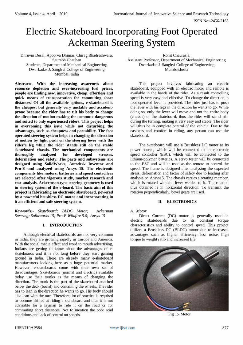
A. Motor
Direct Current (DC) motor is generally used in electric skateboards due to its constant torque
characteristics and ability to control speed. This project
utilizes a Brushless DC (BLDC) motor due to increased
advantages such as higher efficiency, less noise, high
torque to weight ratio and increased life.
Fig 1:- Motor
Volume 4, Issue 4, April – 2019 International Journal of Innovative Science and Research Technology
ISSN No:-2456-2165
IJISRT19AP584 www.ijisrt.com 878
The motor selected here is a 6374 BLDC motor
having power 2.8 kW and kV rating 170. 6374 signifies that the diameter of the motor is 63 mm and the length is 74
mm. The shaft diameter is 10 mm.
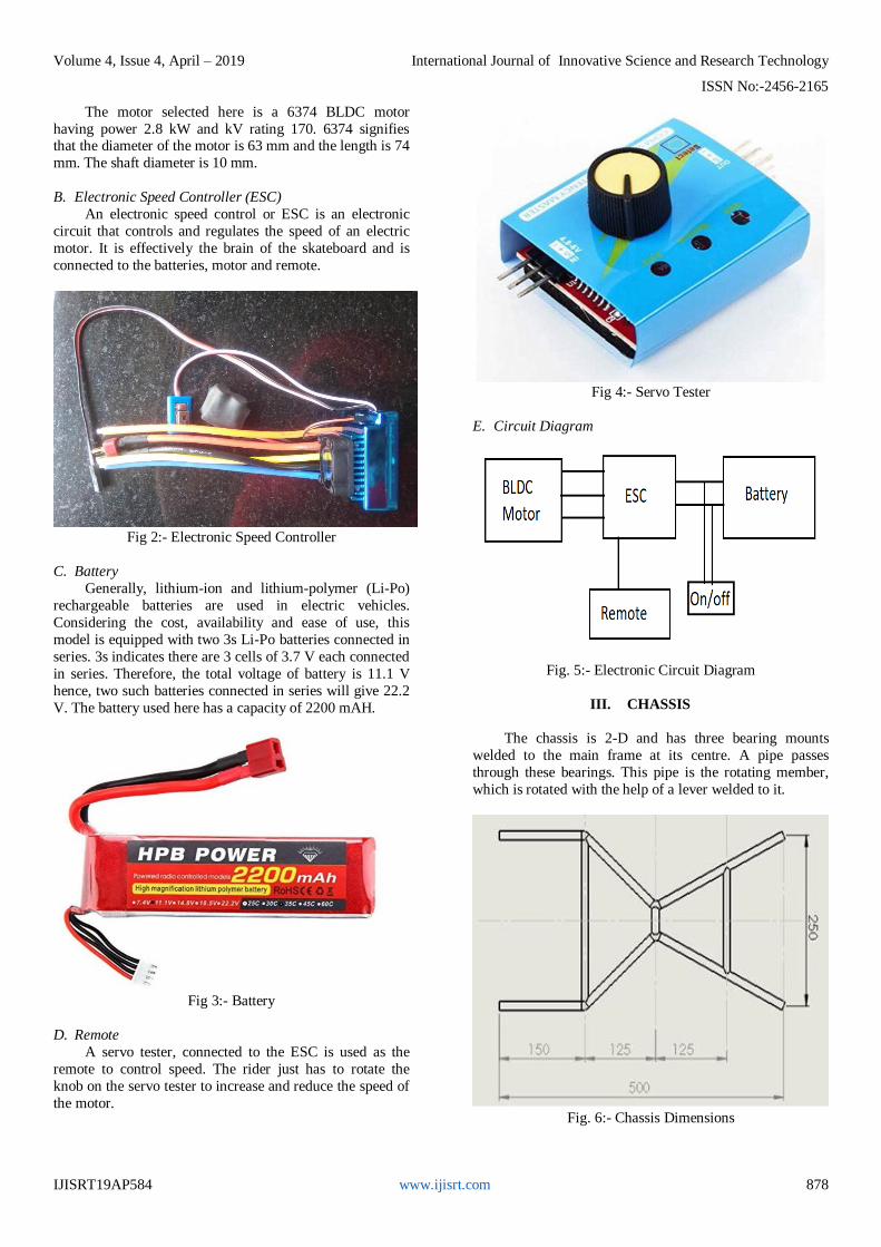
B. Electronic Speed Controller (ESC)
An electronic speed control or ESC is an electronic
circuit that controls and regulates the speed of an electric
motor. It is effectively the brain of the skateboard and is
connected to the batteries, motor and remote.
Fig 2:- Electronic Speed Controller
C. Battery
Generally, lithium-ion and lithium-polymer (Li-Po)
rechargeable batteries are used in electric vehicles.
Considering the cost, availability and ease of use, this
model is equipped with two 3s Li-Po batteries connected in
series. 3s indicates there are 3 cells of 3.7 V each connected
in series. Therefore, the total voltage of battery is 11.1 V
hence, two such batteries connected in series will give 22.2
V. The battery used here has a capacity of 2200 mAH.
Fig 3:- Battery
D. Remote
A servo tester, connected to the ESC is used as the
remote to control speed. The rider just has to rotate the
knob on the servo tester to increase and reduce the speed of
the motor.
Fig 4:- Servo Tester
E. Circuit Diagram
Fig. 5:- Electronic Circuit Diagram
III. CHASSIS
The chassis is 2-D and has three bearing mounts
welded to the main frame at its centre. A pipe passes
through these bearings. This pipe is the rotating member,
which is rotated with the help of a lever welded to it.
Fig. 6:- Chassis Dimensions
Volume 4, Issue 4, April – 2019 International Journal of Innovative Science and Research Technology
ISSN No:-2456-2165
IJISRT19AP584 www.ijisrt.com 879
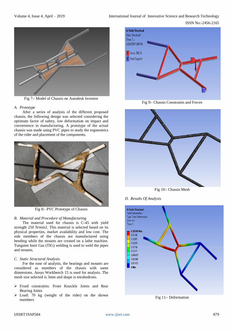
Fig 7:- Model of Chassis on Autodesk Inventor
A. Prototype
After a series of analysis of the different proposed
chassis, the following design was selected considering the
optimum factor of safety, low deformation on impact and
convenience in manufacturing. A prototype of the actual
chassis was made using PVC pipes to study the ergonomics
of the rider and placement of the components.
Fig 8:- PVC Prototype of Chassis
B. Material and Procedure of Manufacturing
The material used for chassis is C-45 with yield
strength 250 N/mm2. This material is selected based on its
physical properties, market availability and low cost. The
side members of the chassis are manufactured using
bending while the mounts are created on a lathe machine.
Tungsten Inert Gas (TIG) welding is used to weld the pipes
and mounts.
C. Static Structural Analysis
For the ease of analysis, the bearings and mounts are
considered as members of the chassis with same
dimensions. Ansys Workbench 15 is used for analysis. The
mesh size selected is 3mm and shape is tetrahedrons.
Fixed constraints: Front Knuckle Joints and Rear
Bearing Joints
Load: 70 kg (weight of the rider) on the shown
members
Fig 9:- Chassis Constraints and Forces
Fig 10:- Chassis Mesh
D. Results Of Analysis
Fig 11:- Deformation
Volume 4, Issue 4, April – 2019 International Journal of Innovative Science and Research Technology
ISSN No:-2456-2165
IJISRT19AP584 www.ijisrt.com 880
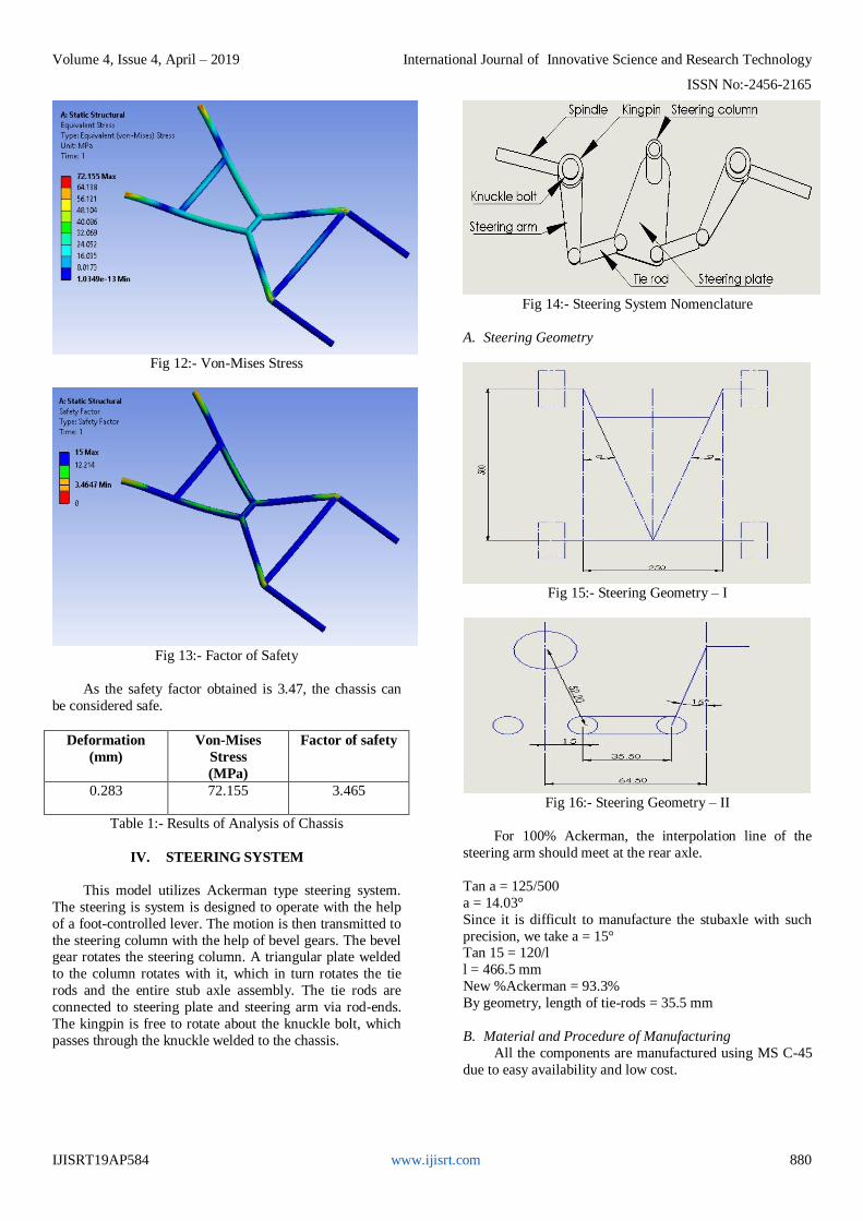
Fig 12:- Von-Mises Stress
Fig 13:- Factor of Safety
As the safety factor obtained is 3.47, the chassis can
be considered safe.
Deformation
(mm)
Von-Mises
Stress
(MPa)
Factor of safety
0.283 72.155 3.465
Table 1:- Results of Analysis of Chassis
IV. STEERING SYSTEM
This model utilizes Ackerman type steering system.
The steering is system is designed to operate with the help
of a foot-controlled lever. The motion is then transmitted to
the steering column with the help of bevel gears. The bevel gear rotates the steering column. A triangular plate welded
to the column rotates with it, which in turn rotates the tie
rods and the entire stub axle assembly. The tie rods are
connected to steering plate and steering arm via rod-ends.
The kingpin is free to rotate about the knuckle bolt, which
passes through the knuckle welded to the chassis.
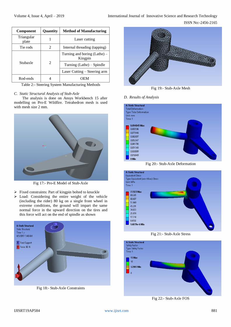
Fig 14:- Steering System Nomenclature
A. Steering Geometry
Fig 15:- Steering Geometry – I
Fig 16:- Steering Geometry – II
For 100% Ackerman, the interpolation line of the
steering arm should meet at the rear axle.
Tan a = 125/500
a = 14.03°
Since it is difficult to manufacture the stubaxle with such
precision, we take a = 15° Tan 15 = 120/l
l = 466.5 mm
New %Ackerman = 93.3%
By geometry, length of tie-rods = 35.5 mm
B. Material and Procedure of Manufacturing
All the components are manufactured using MS C-45
due to easy availability and low cost.
Volume 4, Issue 4, April – 2019 International Journal of Innovative Science and Research Technology
ISSN No:-2456-2165
IJISRT19AP584 www.ijisrt.com 881
Component Quantity Method of Manufacturing
Triangular
plate 1 Laser cutting
Tie rods 2 Internal threading (tapping)
Stubaxle 2
Turning and boring (Lathe) – Kingpin
Turning (Lathe) – Spindle
Laser Cutting – Steering arm
Rod-ends 4 OEM
Table 2:- Steering System Manufacturing Methods
C. Static Structural Analysis of Stub-Axle
The analysis is done on Ansys Workbench 15 after modelling on Pro-E Wildfire. Tetrahedron mesh is used
with mesh size 2 mm.
Fig 17:- Pro-E Model of Stub-Axle
Fixed constraints: Part of kingpin bolted to knuckle
Load: Considering the entire weight of the vehicle
(including the rider) 80 kg on a single front wheel in
extreme conditions, the ground will impart the same
normal force in the upward direction on the tires and
this force will act on the end of spindle as shown
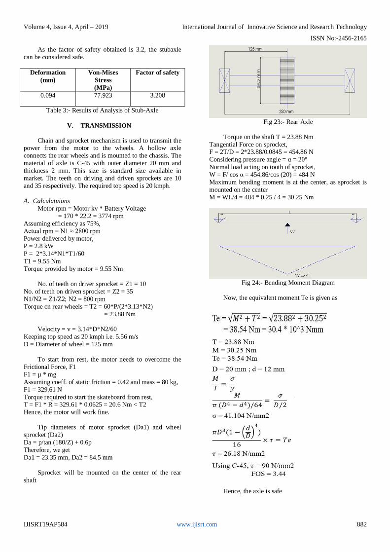
Fig 18:- Stub-Axle Constraints
Fig 19:- Stub-Axle Mesh
D. Results of Analysis
Fig 20:- Stub-Axle Deformation
Fig 21:- Stub-Axle Stress
Fig 22:- Stub-Axle FOS
Volume 4, Issue 4, April – 2019 International Journal of Innovative Science and Research Technology
ISSN No:-2456-2165
IJISRT19AP584 www.ijisrt.com 882
As the factor of safety obtained is 3.2, the stubaxle
can be considered safe.
Deformation
(mm)
Von-Mises
Stress
(MPa)
Factor of safety
0.094 77.923 3.208
Table 3:- Results of Analysis of Stub-Axle
V. TRANSMISSION
Chain and sprocket mechanism is used to transmit the power from the motor to the wheels. A hollow axle
connects the rear wheels and is mounted to the chassis. The
material of axle is C-45 with outer diameter 20 mm and
thickness 2 mm. This size is standard size available in
market. The teeth on driving and driven sprockets are 10
and 35 respectively. The required top speed is 20 kmph.
A. Calculatuions
Motor rpm = Motor kv * Battery Voltage
= 170 * 22.2 = 3774 rpm
Assuming efficiency as 75%, Actual rpm = N1 ≈ 2800 rpm
Power delivered by motor,
P = 2.8 kW
P = 2*3.14*N1*T1/60
T1 = 9.55 Nm
Torque provided by motor = 9.55 Nm
No. of teeth on driver sprocket = Z1 = 10
No. of teeth on driven sprocket = Z2 = 35
N1/N2 = Z1/Z2; N2 = 800 rpm
Torque on rear wheels = T2 = 60*P/(2*3.13*N2)
= 23.88 Nm
Velocity = v = 3.14*D*N2/60
Keeping top speed as 20 kmph i.e. 5.56 m/s
D = Diameter of wheel = 125 mm
To start from rest, the motor needs to overcome the
Frictional Force, F1
F1 = µ * mg
Assuming coeff. of static friction = 0.42 and mass = 80 kg,
F1 = 329.61 N
Torque required to start the skateboard from rest, T = F1 * R = 329.61 * 0.0625 = 20.6 Nm < T2
Hence, the motor will work fine.
Tip diameters of motor sprocket (Da1) and wheel
sprocket (Da2)
Da = p/tan (180/Z) + 0.6p
Therefore, we get
Da1 = 23.35 mm, Da2 = 84.5 mm
Sprocket will be mounted on the center of the rear
shaft
Fig 23:- Rear Axle
Torque on the shaft T = 23.88 Nm
Tangential Force on sprocket, F = 2T/D = 2*23.88/0.0845 = 454.86 N
Considering pressure angle = α = 20°
Normal load acting on tooth of sprocket,
W = F/ cos α = 454.86/cos (20) = 484 N
Maximum bending moment is at the center, as sprocket is
mounted on the center
M = WL/4 = 484 * 0.25 / 4 = 30.25 Nm
Fig 24:- Bending Moment Diagram
Now, the equivalent moment Te is given as
Hence, the axle is safe
Volume 4, Issue 4, April – 2019 International Journal of Innovative Science and Research Technology
ISSN No:-2456-2165
IJISRT19AP584 www.ijisrt.com 883
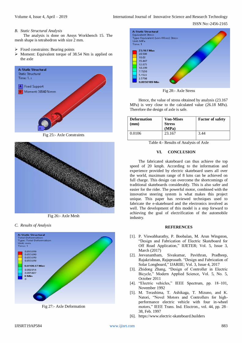
B. Static Structural Analysis
The analysis is done on Ansys Workbench 15. The mesh shape is tetrahedron with size 2 mm.
Fixed constraints: Bearing points
Moment: Equivalent torque of 38.54 Nm is applied on
the axle
Fig 25:- Axle Constraints
Fig 26:- Axle Mesh
C. Results of Analysis
Fig 27:- Axle Deformation
Fig 28:- Axle Stress
Hence, the value of stress obtained by analysis (23.167
MPa) is very close to the calculated value (26.18 MPa).
Therefore the design of axle is safe.
Deformation
(mm)
Von-Mises
Stress
(MPa)
Factor of safety
0.0106 23.167 3.44
Table 4:- Results of Analysis of Axle
VI. CONCLUSION
The fabricated skateboard can thus achieve the top
speed of 20 kmph. According to the information and
experience provided by electric skateboard users all over
the world, maximum range of 8 kms can be achieved on full charge. This design can overcome the shortcomings of
traditional skateboards considerably. This is also safer and
easier for the rider. The powerful motor, combined with the
innovative steering system is what makes this project
unique. This paper has reviewed techniques used to
fabricate the e-skateboard and the electronics involved as
well. The development of this model is a step forward to
achieving the goal of electrification of the automobile
industry.
REFERENCES
[1]. P. Viswabharathy, P. Boobalan, M. Arun Wingston,
“Design and Fabrication of Electric Skateboard for
Off Road Application,” IIJETER; Vol. 5, Issue 3,
March (2017)
[2]. Jeevanantham, Sivakumar, Pavithran, Pradheep,
Rajakrishnan, Rajaprasath. “Design and Fabrication of
Solar Longboard,” IJARIIE; Vol. 3, Issue 4, 2017
[3]. Zhidong Zhang, “Design of Controller in Electric
Bicycle,” Modern Applied Science, Vol. 5, No. 5,
October 2011 [4]. “Electric vehicles,” IEEE Spectrum, pp. 18–101,
November 1992
[5]. M. Terashima, T. Ashikaga, T. Mizuno, and K.
Natori, “Novel Motors and Controllers for high-
performance electric vehicle with four in-wheel
motors,” IEEE Trans. Ind. Electron., vol. 44, pp. 28–
38, Feb. 1997
[6]. https://www.electric-skateboard.builders