Embed Size (px)
Citation preview

Electric Service Standards
Ordinance No. 066, 2016
Utilities Customer Service Office 222 LaPorte Avenue
Fort Collins, CO 80521 Phone: (970) 212-2900
Fort Collins Utilities
700 Wood Street P.O. Box 580
Fort Collins, CO 80522 Phone: (970) 221-6700 Fax: (970) 221-6619
E-mail: [email protected] Web: www.fcgov.com/utilities
Publish Date: 11 February 2022
1
Table of Contents Fort Collins Utilities Electric Service Standards
1. Authority for Regulations ............................................................................ 3
2. Application of Policy .................................................................................... 3
3. Costs ............................................................................................................... 3 3.1. New Development and Redevelopment ............................................................................ 3
3.2. Modifications to Capacity .................................................................................................. 4
4. General Construction ................................................................................... 4 4.1. Underground Construction Required .............................................................................. 4
4.2. Type of Service ................................................................................................................... 4
4.3. Transformers ...................................................................................................................... 5
4.4. Customer Load ................................................................................................................... 5
4.5. Attachment to Poles ........................................................................................................... 6
5. Residential Service Construction ................................................................ 6 5.1. Single Family Detached Dwelling Unit ............................................................................ 6
5.2. Mobile Home Parks ............................................................................................................ 7
6. Project Development Plan ........................................................................... 8
7. Commercial Service Construction .............................................................. 8 7.1. General ................................................................................................................................ 8
7.2. Multiple Occupancy (duplexes, townhomes, and apartments) ...................................... 9
8. Metering ......................................................................................................... 9 8.1. Meter Locations and Clearances ...................................................................................... 9
8.2. Self-Contained Meter Sockets ......................................................................................... 10
8.3. Current Transformer (CT) Metering ............................................................................. 12
8.4. Residential Meter Pedestals ............................................................................................. 16
8.5. Commercial Meter Pedestals ........................................................................................... 16
8.6. Cold Sequence Metering .................................................................................................. 17
8.7. Parallel Generation Metering ......................................................................................... 18
8.8. Restrictions on Master Metering .................................................................................... 19
9. Construction Coordination Sequence ....................................................... 19 9.1. General .............................................................................................................................. 19
9.2. Prerequisite to Construction ........................................................................................... 19
9.3. Street Crossing Option .................................................................................................... 20
9.4. Trenching Option ............................................................................................................. 20
2
9.5. Joint Use Construction .................................................................................................... 20
10. Easements .................................................................................................... 20
11. Interconnection of Qualifying Parallel Generation Facilities ................ 21 11.1. Application ........................................................................................................................ 21
11.2. Initial Start-Up ................................................................................................................. 21
11.3. Facility Design and Construction .................................................................................... 21
11.4. Facility Operation and Maintenance .............................................................................. 22
11.5. Changes in Facility or Capacity Rating ......................................................................... 22
12. Working Adjacent To Overhead Lines .................................................... 22
13. Locate Policy ............................................................................................... 22
14. Contractor Access to Transformer Secondary Compartments ............. 22
15. Other Rules and Regulations ..................................................................... 23
16. Design Drawings ......................................................................................... 23
17. Variance from Electric Service Standards ............................................... 23
18. Appeals ......................................................................................................... 23
Glossary ............................................................................................................. 25
3
City of Fort Collins Utilities Electric Service Standards
1. Authority for Regulations
This policy, and the regulations it implements, are authorized by Section 26- 463 of the Code of the City of Fort Collins and shall be available for public review at the Fort Collins Utility Service Center and the Office of the City Clerk of the City of Fort Collins.
2. Application of Policy
This policy applies to all construction, new development, redevelopment or remodeling. New requirements in this revision shall apply to all construction, new development, redevelopment or remodeling projects with a building permit application date after the latest revision date of this document. By obtaining a permit, the contractor agrees to abide by the Electric Service Standards in effect at the permit application date.
3. Costs
3.1. New Development and Redevelopment
Cost estimates from preliminary plats will be furnished on request to developers for planning purposes (based on average electric costs developed by the Fort Collins Utilities (hereinafter called the Utilities) from previously completed projects). Developers will receive a firm price for the underground electric system for a subdivision, mobile home park or project development plan after the plat has been finalized and the number, size and location of points of service has been determined.
When the developer requests the actual construction of the project be started, a payment of 100 percent of the invoiced price will be required. Under special circumstances, the Utility, at it’s discretion, may begin construction prior to full payment. Under no circumstances will the electric system be energized prior to full payment of the invoiced price. Payment need only be paid on the portion of the underground electric system which is to be constructed and not necessarily on the whole subdivision project, provided that such portion is suitable for partial electric service. Quoted firm prices will include off-site facilities, primaries and streetlights. The owner will be charged for electric services not paid for by the developer. The underground electrical system will be installed in two phases:
1. Phase one includes the installation of the primary conduit, transformer vaults, primary conductor and customer service provisions from the transformer vault to the nearest lot corner or on-site transformer. The electrical system will be energized following receipt of payment of all project fees and charges.
2. Phase two includes the installation of the customer's service to the lot corner or on-site transformer or meter socket. Service will be installed upon mutual agreement, as to point of-service and meter location.
Modifications to the development plans requiring field changes in the electric system and unforeseen construction obstacles such as frost and rocky soil conditions will be charged on a change order basis and will be coordinated with the developer prior to proceeding with the work.
4
3.2. Modifications to Capacity For remodeling or other modifications where the customer's electric panel capacity is increased and where development charges have not previously been paid, development charges (off-site facilities, primary and streetlights) are applicable to the increased capacity on a prorated basis. All charges for on-site costs are applicable per the Line Extension Policy contained within Municipal Code sections 26-473, 26-474, and 26-475.
4. General Construction
4.1. Underground Construction Required
4.1.1. All electric utility lines and line extensions shall be underground. Permanent buildings or structures shall not be located directly over underground electric utility facilities.
4.1.1.1. Locations and numbers of transformers and other electric facilities shall be coordinated with the Utility and the Utility shall make the final determination.
4.1.2. Service loops shall generally be installed underground. Overhead service loops shall be installed only at the Utilities’ discretion.
4.1.3. If the property of the customer does not abut on the right-of-way of the Utilities’ distribution system, it shall be the customer’s responsibility to provide adequate easements or bring wiring to a point designated by the Utilities.
4.2. Type of Service
4.2.1. Electric service shall be delivered to the customer at one point of delivery for each
premise. 4.2.2. Typically, the Utilities will provide these service types:
Single phase 3 wire 120/240 volt, Single phase 3 wire 208Y/120 volt (available at the discretion of the
Utility in circumstances where an existing three-phase transformer will serve a new single-phase load)
Three phase 208Y/120 volt 4 wire service, or Three phase 480Y/277 volt 4 wire service.
Other service voltages or types must be approved by the Utilities. 4.2.3. If the customer desires electric service at voltages, either primary or secondary, other
than those typically available from the Utilities’ distribution system, the customer shall furnish, own and maintain all special transformers and special control equipment necessary to supply such voltage or service. If special metering shall be required in such cases it shall be specified by the Utilities and the costs thereof shall be paid by the customer. Such special meters, however, shall be and remain the property of the Utilities and shall be tested and maintained by the Utilities.
4.2.4. Where service is supplied at primary voltages, the customer shall provide, own, operate and maintain all facilities beyond the point of delivery at the end of the primary service unless specific arrangements are made to the contrary.
4.2.5. Permanent Service Unless specific arrangements are made to the contrary, electric service shall be considered rendered on a continuous, permanent basis subject to termination as provided in Municipal Code.
4.2.6. Temporary Service 4.2.6.1. Any temporary electric service lines required by the developer for
construction purposes before the permanent service is completed shall be at the expense of the developer and consistent with Municipal Code.

5
4.2.6.2. At the option of the Utilities, the developer will be billed for the actual or estimated cost of construction, plus estimated retirement costs. There will be no charge for recoverable materials.
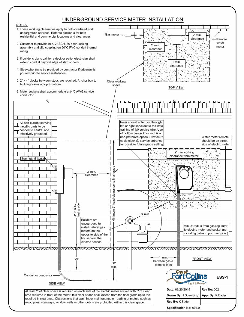
4.2.6.3. For residential single-family detached construction only, a 50-amp temporary power pedestal will be provided to the developer consistent with the requirements in drawing ESS-2.
4.3. Transformers
4.3.1. Generally, the Utilities shall install, own and maintain all transformers required to
deliver service at the Utilities’ standard secondary voltages. 4.3.2. The customer shall furnish and maintain sufficient space for the installation of the
Utilities’ transformers and other equipment necessary to properly render electric service to the customer. Please see drawings ESS-4, ESS-5, ESS-6, ESS 6.1, ESS-6.2, ESS-7, and ESS-8 in Section 16 – Design Drawings.
4.3.2.1. For situations where a building is being constructed with minimal or no lot line setback, a variance may be considered with express written consent from the Light & Power Electrical Engineering project manager to place the transformer in an alcove.
4.3.2.2. An alcove is an exterior space that is recessed into a building or wall. The alcove’s width can vary depending on the transformer needed to serve the building (while maintaining appropriate clearance requirements), but the height must be at least 30 feet above the tallest transformer in the alcove to accommodate equipment needed to set or maintain the transformer. Utilities will provide final transformer dimensions after confirming the service requirements. Please consult the Light & Power Electrical Engineering project manager.
4.3.2.2.1. The alcove walls and ceiling shall have a minimum 3-hour fire rating and shall be constructed of reinforced concrete.
4.3.2.2.2. The alcove floor shall be at street level, flush with or elevated no more than six inches above the adjacent sidewalk or drivable surface, and must be designed to accommodate the weight of the transformer and associated installed equipment. The adjacent drivable surface shall allow 30 feet of maneuvering room for vehicle access (as shown in Drawing ESS 6.1) to set or remove the transformer.
4.3.3. When service is delivered at primary voltage, the customer shall generally own, install and maintain all transformers that meet Fort Collins Utilities current specifications at the time of installation.
4.4. Customer Load
4.4.1. Motor Load and Protection
4.4.1.1. Single-phase motors operated at 120 volts shall be limited to less than 1 horsepower (hp) in size. Single-phase motors 1 hp or greater shall be operated at 240 volts and shall have a maximum locked rotor current limit of 75 amps. The Utilities’ approval must be obtained prior to installing any single-phase motor with locked rotor current in excess of this limit. The following information shall be provided to the Utilities when seeking approval:
Horsepower rating Nameplate full-load amps Nameplate locked rotor amps Nameplate voltage Frequency of starts per time unit Motor NEMA code letter
Note: Central air conditioning units are subject to the requirements of this section.

6
4.4.1.2. The customer shall be responsible for providing protection to 3-phase motors and equipment against damage from overvoltage, undervoltage, single and reversed phasing conditions.
4.4.1.3. Under some conditions, Utilities may require the installation of reduced voltage or other types of starting equipment. Such equipment may be required where, in the opinion of the Utilities, the starting frequency adversely affects service rendered to other customers. Consult the Utilities prior to acquiring motors.
4.4.2. Load Balance 4.4.2.1. For single phase, three wire services, the current carried by the neutral shall
not be more than 15% of the current carried in either of the other wires. 4.4.2.2. For three phase services, the customer’s load in any phase shall not be
greater than 15% more than the load in either of the other two phases.
4.5. Attachment to Poles
4.5.1. Attachments to the Utilities’ poles or lighting standards shall not be permitted except upon specific written authority of the Utilities or license with the City of Fort Collins.
4.5.2. The attachment of TV antennae or other non-telecommunications objects is specifically prohibited without Utilities permission.
4.5.3. Attachment of communications circuits such as telephone, community antennae systems or other communication media may be made, with the Utilities permission provided that a license agreement has been entered into between the City of Fort Collins and those desiring to make such attachments. Said attachments shall conform to the requirements of the latest edition of the National Electric Safety Code and additional requirements, if any, by the Utilities.
5. Residential Service Construction
This section of the policy applies to new subdivided areas where curb (except for radius sections) and grading have been completed but where gas and telephone utilities and paving have not been installed (see Section 9 - Construction Coordination Sequence). A single family detached residence is defined as a single residence platted on its own lot. Unless capacity demand is substantially higher than normal as determined by the Utilities Executive Director or the Executive Director’s designee, residential service construction must utilize a single-phase primary system complete with transformer vaults and transformers designed to convert the primary system voltage to the standard residential voltage of 120/240 volts, three wire single-phase, including the three-wire electric service to the meter location. For detailed metering equipment and location information, reference Section 8 – Metering. The electric facilities will generally be installed underground behind the curb or sidewalk with a minimum cover of 30 inches and will generally be completely at or below grade utilizing front lot line construction. Streetlighting will be installed in accordance with the City of Fort Collins design criteria and standards for streets.
5.1. Single Family Detached Dwelling Unit
5.1.1. The secondary electric service fee is to be paid at the time the building permit is issued.
5.1.2. A single family detached residence served by a single-secondary service with an electric panel of 200 amps or less is subject to the requirements in this section.
7
5.1.2.1. Before electric service is installed, the meter socket (furnished by the owner) shall be installed and the meter socket installation must be approved by the Building Inspection Department.
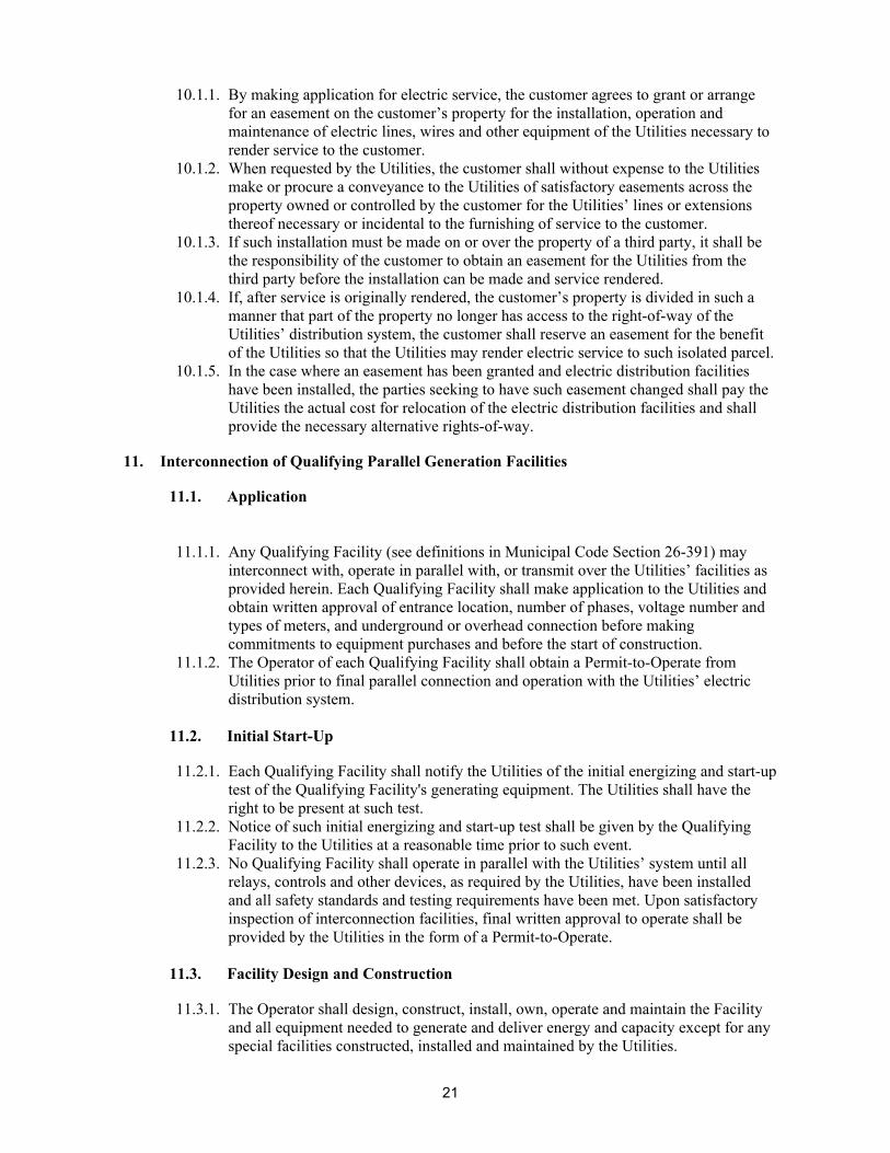
5.1.2.2. A rigid non-metallic conduit attached from the socket to a point 24 inches below finished grade, must be provided. The conduit size shall be as specified by the Utilities and shall not be less than 2 inches inside diameter. See drawing ESS-1 for more details.
5.1.3. The Utilities will furnish, install and maintain the service conductors to the meter socket.
5.1.4. The Utilities will make the service conductor connection at the point of delivery and at the secondary spades of the transformer, junction box or electric meter socket enclosure.
5.1.5. All construction and maintenance on the customer side of any provision for customer service wire connection including the making of such service connections shall be done by someone other than the Utilities.
5.1.6. A single residence served by a single-phase secondary service with an electric panel greater than 200 amps intended for self-contained metering is subject to the requirements in this section.
5.1.6.1. The meter socket (furnished by the owner) shall be installed and the meter socket installation must be approved by the Building Inspection Department.
5.1.6.2. A rigid non-metallic conduit attached from the socket to a point 24 inches below finished grade, must be provided. The conduit size shall be as specified by the Utilities and shall not be less than 2 inches inside diameter. See drawing ESS-1 for more details.
5.1.6.3. The owner will furnish and install the service conductors from the point of delivery to the meter socket.
5.1.6.4. The Utilities will make the service conductor connection at the point of delivery and at the secondary spades of the transformer or junction box.
5.1.6.5. All construction and maintenance on the customer side of any provision for customer service wire connection including the making of such service connections shall be done by someone other than the Utilities.
5.1.7. A single residence served by a service requiring greater than 320 amps continuous will be treated as a commercial installation and require the use of instrument metering.
5.1.7.1. For more detailed information on instrument metering requirements and responsibilities, reference Section 8.3 on current transformer metering.
5.1.7.2. Reference Section 7 for requirements and responsibilities related to installation of commercial services.
5.2. Mobile Home Parks
5.2.1. Electric facilities will generally be installed on rear lot lines (unless otherwise approved by the Utilities) to ganged meter sockets with breakers and will be installed and billed with the first phase of construction. Single-position utility meter pedestals may also be used provided they adhere to the same sections as applies to ganged meter sockets (Section 8.4).
5.2.2. Meter sockets with breakers shall be furnished, installed and maintained by the owners. Meter sockets and breakers shall be Utilities-approved devices (see Section 8 – Metering).
5.2.3. A 2-inch rigid non-metallic utility service conduit (or conduits as required) from the meter sockets with a cover of 24 inches (± 6 inches) from finished grade, using a 24 inch radius 90-degree bend is to be installed by the owner and approved by the building inspector.

8
5.2.4. If the meter sockets are not building mounted, a manufactured meter pedestal that meets requirements in Section 8.4 shall be utilized.
6. Project Development Plan
The applicable service rules as described under the residential and commercial construction headings apply.
7. Commercial Service Construction
7.1. General
7.1.1. Commercial service construction will be considered on an individual basis depending upon size, type and characteristics of the load requirement.
7.1.2. The Utilities will endeavor to provide special service voltages and/or connections when a Utilities-approved document is presented, provided that such document or documents accurately and completely describe the owner's load and desired entrance needs.
7.1.3. Service requirements, construction costs and payment terms will be provided on request. Early contact with the Utilities during the planning stages is essential. The Utilities will not be obligated to provide special service voltages, if planning has not been coordinated with the Utilities.
7.1.4. Entrance requirements including location, number of phases, voltage, amperage per meter, number of meters, and underground or overhead must be determined with the Utilities at an early date (also see Section 8 – Metering).
7.1.5. Typically, the Utilities will provide these services: Single phase 3 wire 120/240 volt, Single phase 3 wire 208Y/120 volt (generally only approved for existing
installations), Three phase 208Y/120 volt 4 wire service, or Three phase 480Y/277 volt 4 wire service.
Other service voltages or types must be approved by the Utilities. 7.1.6. Padmounted transformers that serve commercial services shall adhere to location
clearance and work access requirements displayed in design drawings ESS-4, ESS-5, ESS-6, ESS-7, and ESS-8 (see Section 16 – Design Drawings).
7.1.7. Because of planned underground service facilities and requirements to convert overhead lines to underground, the location or characteristics of existing or prior electric service facilities will not determine the location or service characteristics of a new or modified electric service entrance.
7.1.8. Except when the Utilities determines that underground is not feasible, services will be installed underground.
7.1.9. The owner will be required to furnish, install and maintain all circuits and equipment on the customer side of the point of delivery.
7.1.10. On three phase commercial services there is a limit to the number of cables per phase that the customer may install. For installations utilizing a 12 conductor set screw connector on each bushing, no cable shall exceed 500 kcmil in size and no service shall exceed 48 cables (i.e. 12 cables/bushing). For installations utilizing two-hole crimp on lug connectors that bolt onto the 10-hole spade, no service shall exceed 40 cables (i.e. 10 cables/bushing). Size and number of conduits installed shall fit within the secondary window opening on the transformer pad.
7.1.11. For detailed metering equipment requirements and location information, reference Section 8 – Metering.
7.1.12. Streetlighting will be installed by Utilities in accordance with the City of Fort Collins' design criteria and standards for public streets
9
7.1.13. Any area floodlighting requirements will be set forth in a service contract as defined in Fort Collins Municipal code in Section 26-471.
7.2. Multiple Occupancy (duplexes, townhomes, and apartments)
7.2.1. Multiple occupancy residences are defined as residences with one or more shared walls. Multiple occupancy residences are considered to be commercial services and shall meet the requirements included in Section 7.
7.2.2. Where service is provided to individual customers located in a structure designed for multiple occupancy, meters shall be grouped for service from a single circuit secondary service.
7.2.3. The location shall be on the exterior for multiple occupancy, unless otherwise approved by the Utilities.
7.2.4. The owner shall furnish and install UL approved meter sockets and rigid (non-metallic) service entrance conduit to a point 24 inches below finished grade. The service conduit shall be not less than 2-1/2 inches inside diameter or as specified by the Utilities.
7.2.5. The owner shall also provide a one-inch conduit from the transformer to an accessible point inside the building near the meter installation for future use by the Utilities.
7.2.6. The owner shall furnish, install and maintain specified service conductors to the transformer terminals or nearest secondary junction box or vault.
7.2.7. On single phase commercial services the limit of the number of cables per bushing that the customer may install is eight. The Utilities will provide a set screw connector with a maximum of eight landing positions and no cable shall exceed 350 kcmil in size.
7.2.8. Service conductor size and insulation shall be as approved or specified by the Utilities.
7.2.9. Trenches for secondary services to apartment complexes shall conform to all applicable codes and may be subject to inspection.
8. Metering
8.1. Meter Locations and Clearances
8.1.1. The location of meters and metering equipment will be approved by Fort Collins Utilities only where they are readily accessible at all times for reading, testing, inspecting, and other maintenance purposes. The preferred location for easy reading and access by the Utilities is on a side wall of the structure as close to the street side of the structure as possible and shall not be in an enclosed or fenced area of the property.
8.1.2. Outdoor meters shall not be installed where they will interfere with traffic, sidewalks, driveways, or where they will obstruct the opening of doors or windows, or in any location that may be considered hazardous or cause damage to the metering equipment.
8.1.2.1. Where service is supplied to individual customers located in a structure designed for multiple occupancy, the individual outdoor meters will be grouped at a point nearest the service attachment and must be as specified in the excerpts from Article 370 of the National Electrical Code.
8.1.2.2. The mounting heights for multiple meter stacks will be no lower than 24 inches from final grade to the center of the lowest meters and will be no higher than 78 inches from grade to the center of the highest meters. Any
10
variation from these mounting heights requires prior approval from the Fort Collins Utilities Electric Meter Shop.
8.1.3. Indoor meter installations pose access and radio communication issues, and are not acceptable without express written consent or a variance from Fort Collins Utilities Electric Meter Shop with the following requirements:
8.1.3.1. Customer may be required to provide a 2” conduit between the meter room and an accessible location on the exterior of the building.
8.1.3.2. The customer shall provide Utilities personnel access to the building and meter room(s) at all times for reading, testing and other maintenance and/or safety purposes. The customer must provide a suitable keyed or keyless entry for Utilities access prior to energizing the service.
8.1.3.3. The meter room(s) shall be dedicated to utility metering only. Meter room(s) are not permitted to be used as customer’s storage area.
8.1.4. Meter sockets will be plumb and securely fastened to the building wall (at framing members).
8.1.5. The mounting heights for single meters, self-contained meter sockets, and transformer rated meter sockets shall be 48 to 72 inches above finished grade and meter pedestals shall be no lower than 36 inches from final grade to center of the meter.
8.1.6. Meter sockets must NOT be installed under projections lower than six feet to allow for reading and maintenance of equipment.
8.1.7. A minimum of three feet of clear space must be left in front of the meter for reading and maintenance of equipment.
8.1.8. A minimum of two feet of clear space measured from any part of the meter socket to all conduits, pipe, walls, etc. must be maintained for servicing.
8.1.9. Electric meters and CT cabinets will be located at least three feet radially from gas meter regulators.
8.1.10. The builder is required to install the electric meter socket(s) on the same side as the electric service ‘stub’.
8.1.11. Builders are also encouraged to install the natural gas meter(s) on the opposite side of the house from the electric service.
8.1.12. The electric service trench must be a minimum of 3 feet from the natural gas service trench, and the electric and gas services shall not cross each other.
8.1.13. Meter location and clearance requirements are also shown in design drawing ESS-1.
8.2. Self-Contained Meter Sockets
8.2.1. All meter sockets (residential and commercial), except in the case of CT metered facilities, shall be purchased and installed by the electrical contractor from suppliers. All commercial self-contained meter sockets shall be cold sequenced. Please see Section 8.2.9 and 8.6 for more information on cold sequencing.
8.2.2. The owner of the facility or residence being served is responsible for the repair and maintenance of the meter socket, including ganged meter sockets.
8.2.3. All self-contained meter sockets rated for 320 amps and below shall be wired by the customer.
8.2.4. Fort Collins Utilities will wire CT meter sockets from CTs to the meter socket. 8.2.5. Meter sockets shall be furnished and installed by the owner or their agent as a
contribution in aid to construction on a non-refundable basis. All meter sockets, meter stacks, and modular metering systems will be manufactured in accordance with the latest revision of the following: ANSI C.12.7, ANSI/UL 414, and NEMA 250, as well as all other applicable code and standards, with revisions and modifications as contained in the specification. They shall be labeled according to their listing and installed and used in accordance with their rating and labeling.
11
8.2.6. Fort Collins Utilities reserves the right not to energize an under-rated or unapproved meter socket.
8.2.7. Damaged meter sockets shall be replaced and installed by the owner or their agent at no expense to Fort Collins Utilities.
8.2.8. Residential (single and multiple occupancy) Meter Sockets
8.2.8.1. This section covers installations not exceeding 320 amps or 300 volts. 8.2.8.2. Residential meter sockets shall be UL-approved, 4- or 5-terminal sockets (5-
terminal required for 120/208 volt service) and be rated for a minimum of 100 amps.
8.2.8.3. Fort Collins Utilities will connect to the utility source side of the residential meter socket.
8.2.8.4. Each meter socket shall be plainly and permanently marked to indicate which apartment or unit it supplies. The labeling shall be located or attached to the exterior non-removable portion of the meter socket or at the individual meter main disconnect. The marking shall be the same as the mailing address for each unit. The owner or developer shall be responsible for electricity delivered through unmarked, illegible or incorrectly labeled meter sockets. All expenses incurred by the Utilities related to correcting improperly labeled meters will be billed to the developer or owner whose responsibility it shall be to pay such expenses within 30 days of receipt of said billing.
8.2.9. Commercial Meter Sockets
8.2.9.1. This section describes requirements for commercial self-contained meter sockets. In addition to the requirements in this section, installations not exceeding 320-amp meter socket rules in Section 8.2.8 – Residential Meter Sockets shall apply. All three-phase installations exceeding 200 amps and 240 volts shall follow rules in Section 8.3 – Current Transformer (CT) Metering Equipment.
8.2.9.2. All commercial self-contained meter sockets, single and three-phase, shall be cold sequenced. For cold sequence metering requirements, see Section 8.6.
8.2.9.3. The owner or their agent shall install the meter socket (furnished by the Utilities). The owner shall furnish a one-inch conduit from the secondary side of the transformer to an accessible point inside the building near the meter installation for future use by the Utilities.
8.2.10. Electrical Ratings
8.2.10.1. All sockets/housings shall be rated 300 Volts or 600 Volts as detailed in ANSI C.12.7.
8.2.10.2. If available fault current at the meter socket is greater than 10,000 symmetrical RMS amps, current-limiting fuses shall be selected to limit faults to 10,000 symmetrical RMS amps at the meter. A fault-current-limiting breaker may be utilized provided that a fault current analysis report performed and signed by a registered professional engineer is submitted and approved by Fort Collins Utilities Electric Meter Shop. Fault current calculations in report shall be based on worst case utility electric system and transformer impedance.
8.2.10.3. All sockets/housings shall have a minimum 10,000 ampere AISC rating. Installations other than single family residential and mobile home parks shall contact the Electric Meter Shop for maximum available short-circuit current, which shall determine whether a higher AISC rating is necessary.
8.2.10.4. Meter sockets shall accommodate a #4/0 AWG service conductor. 8.2.11. Construction
8.2.11.1. All utility source side compartments shall accommodate Fort Collins Utilities’ seal regardless of whether the compartment is designed to house a meter.
12
8.2.11.2. A temporary meter cover plate is required. No metallic material is acceptable.
8.2.11.3. A flash shield is required for 277/480 Volt services. 8.2.11.4. All meter housings shall be outdoor weather-resistant type.
8.2.12. Covers 8.2.12.1. Each socket in a multi-socket stack shall have an individual cover and
sealing provision. 8.2.12.2. Only one-piece ringless covers are acceptable. 8.2.12.3. Covers shall be designed for sealing with a padlock type seal and removable
without removing any screws, bolts, or nuts. 8.2.12.4. Cover shall be designed to prevent removal of any portion without first
removing the seal. 8.2.13. Jaws and Terminal Block
8.2.13.1. Any tension springs shall be permanently captive. 8.2.13.2. Lugs/terminals shall be suitable for use with copper or aluminum conductors. 8.2.13.3. Lugs shall be hex-head type with captive bolts.
8.2.14. All meter sockets shall be equipped with a lever bypass with the same rating as the meter socket. Horn bypass meter sockets are expressly prohibited.
8.3. Current Transformer (CT) Metering
8.3.1. General 8.3.1.1. For loads exceeding 320 Amps meter sockets will be furnished by the
Utilities and installed by the owner or their agent. Metering will be instrument transformer rated, with instrument transformers furnished by the Utilities. The owner or their agent shall furnish and install a one-inch conduit from the meter socket to the instrument transformer location.
8.3.1.2. Instrument transformers and associated equipment such as enclosures, racks, poles, cable, terminations, insulators, etc., for primary metering shall be at the expense of the customer on a non-refundable basis. The owner or their agent shall install the meter socket (furnished by the Utilities) and shall furnish and install a one-inch conduit from the meter socket to the instrument transformer location. The owner shall furnish a minimum one-inch conduit from the secondary side of the transformer and capped at an accessible point near the meter installation and marked for future use by the Utilities. If the meter socket is located more than 25 feet in one direction from the location of the instrument transformers, contact Electric Meter Shop for approval.
8.3.1.3. Each meter socket and panel shall be plainly and permanently marked to indicate which unit it supplies. The labeling shall be located or attached to the exterior non-removable portion of the meter socket or at the individual meter main disconnect. If the main disconnect is not immediately next to the meter, then both shall be labeled. The meter socket shall be marked with a stamped brass, aluminum, stainless steel or outdoor rated, UV resistant engraved plastic tag (lamacoid or phenolic) securely attached (riveted or screwed) to the meter socket. The marking is to be the same as the mailing address for each unit. The owner or developer will be responsible for electricity delivered through unmarked, illegible or incorrectly labeled meter sockets. All expenses incurred by the Utilities related to correcting improperly labeled meters will be billed to the developer or owner, whose responsibility it shall be to pay such expenses within 30 days of receipt of said billing.
13
8.3.1.4. Current transformers (CTs) are required if load (main size) is over 320 amps. CT and meter socket location must be approved by Fort Collins Utilities before installation. Under no circumstances will CTs or PTs be installed on secondary overhead lines, in padmounted transformers or inside gutters, raceways, or enclosures not designated for instrument transformers. Contact Electric Project Engineering with any questions on suitable locations. All CTs will be furnished by Fort Collins Utilities for installation by the customer. All instrument transformers, except in primary metering instances, are owned and maintained by Fort Collins Utilities. When CTs are to be mounted in the customer’s switchgear, dimensions of the cross section of bus where CTs are to be installed shall be submitted to the Fort Collins Utilities Electric Meter Shop for proper CT sizing. Access to the CTs shall not be blocked by wiring or equipment in any type of installation (e.g. cabinet, switchgear, service connection cabinet,). If the customer’s switchgear is located indoors or below grade, the CTs shall be located outdoors in a service cabinet or wall mounted CT enclosure that is readily accessible for Fort Collins Utilities personnel at all times. CTs are not allowed in any transformers.
8.3.1.5. In the event that CTs are mounted on buss bars, in customer switchgear or CT cabinets, the customer will provide a suitable terminal for a #12 copper wire on the neutral (and on each phase conductor in the case of window-type rather than bar-type CTs). Such terminals may consist of any appropriate lug or a #10 screw type terminal.
8.3.1.6. Customer-owned equipment, other than service conductors, shall not be installed in the space dedicated to instrument transformers.
8.3.1.7. Any exception to the CT-metering practices outlined above or below will require the approval of Fort Collins Utilities Electric Meter Shop prior to installation.
8.3.2. CT Cabinet Requirements - General 8.3.2.1. Where CT cabinets are required, they will be furnished and installed on the
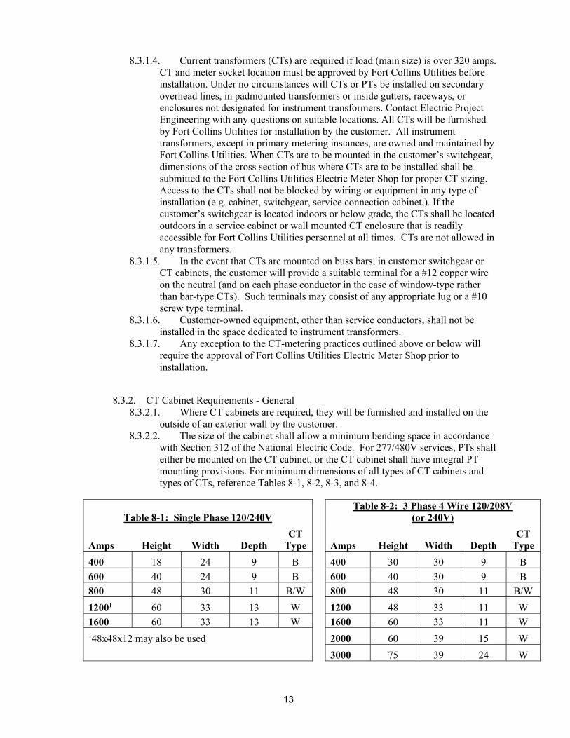
outside of an exterior wall by the customer. 8.3.2.2. The size of the cabinet shall allow a minimum bending space in accordance
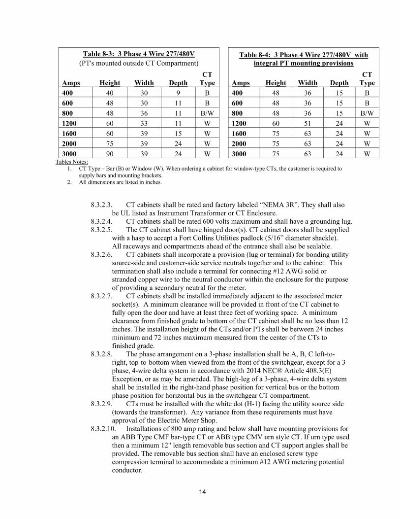
with Section 312 of the National Electric Code. For 277/480V services, PTs shall either be mounted on the CT cabinet, or the CT cabinet shall have integral PT mounting provisions. For minimum dimensions of all types of CT cabinets and types of CTs, reference Tables 8-1, 8-2, 8-3, and 8-4.
Table 8-1: Single Phase 120/240V Table 8-2: 3 Phase 4 Wire 120/208V
(or 240V)
Amps Height Width Depth CT
Type Amps Height Width Depth CT
Type
400 18 24 9 B 400 30 30 9 B
600 40 24 9 B 600 40 30 9 B
800 48 30 11 B/W 800 48 30 11 B/W
12001 60 33 13 W 1200 48 33 11 W
1600 60 33 13 W 1600 60 33 11 W 148x48x12 may also be used 2000 60 39 15 W
3000 75 39 24 W
14
Table 8-3: 3 Phase 4 Wire 277/480V Table 8-4: 3 Phase 4 Wire 277/480V with integral PT mounting provisions (PT's mounted outside CT Compartment)
Amps Height Width Depth CT
Type Amps Height Width Depth CT
Type
400 40 30 9 B 400 48 36 15 B
600 48 30 11 B 600 48 36 15 B
800 48 36 11 B/W 800 48 36 15 B/W
1200 60 33 11 W 1200 60 51 24 W
1600 60 39 15 W 1600 75 63 24 W
2000 75 39 24 W 2000 75 63 24 W
3000 90 39 24 W 3000 75 63 24 W Tables Notes:
1. CT Type – Bar (B) or Window (W). When ordering a cabinet for window-type CTs, the customer is required to supply bars and mounting brackets.
2. All dimensions are listed in inches.
8.3.2.3. CT cabinets shall be rated and factory labeled “NEMA 3R”. They shall also be UL listed as Instrument Transformer or CT Enclosure.
8.3.2.4. CT cabinets shall be rated 600 volts maximum and shall have a grounding lug. 8.3.2.5. The CT cabinet shall have hinged door(s). CT cabinet doors shall be supplied
with a hasp to accept a Fort Collins Utilities padlock (5/16” diameter shackle). All raceways and compartments ahead of the entrance shall also be sealable.
8.3.2.6. CT cabinets shall incorporate a provision (lug or terminal) for bonding utility source-side and customer-side service neutrals together and to the cabinet. This termination shall also include a terminal for connecting #12 AWG solid or stranded copper wire to the neutral conductor within the enclosure for the purpose of providing a secondary neutral for the meter.
8.3.2.7. CT cabinets shall be installed immediately adjacent to the associated meter socket(s). A minimum clearance will be provided in front of the CT cabinet to fully open the door and have at least three feet of working space. A minimum clearance from finished grade to bottom of the CT cabinet shall be no less than 12 inches. The installation height of the CTs and/or PTs shall be between 24 inches minimum and 72 inches maximum measured from the center of the CTs to finished grade.
8.3.2.8. The phase arrangement on a 3-phase installation shall be A, B, C left-to-right, top-to-bottom when viewed from the front of the switchgear, except for a 3-phase, 4-wire delta system in accordance with 2014 NEC® Article 408.3(E) Exception, or as may be amended. The high-leg of a 3-phase, 4-wire delta system shall be installed in the right-hand phase position for vertical bus or the bottom phase position for horizontal bus in the switchgear CT compartment.
8.3.2.9. CTs must be installed with the white dot (H-1) facing the utility source side (towards the transformer). Any variance from these requirements must have approval of the Electric Meter Shop.
8.3.2.10. Installations of 800 amp rating and below shall have mounting provisions for an ABB Type CMF bar-type CT or ABB type CMV urn style CT. If urn type used then a minimum 12" length removable bus section and CT support angles shall be provided. The removable bus section shall have an enclosed screw type compression terminal to accommodate a minimum #12 AWG metering potential conductor.
15
8.3.2.11. Installations from 1000 to 4000 amp rating shall have a minimum 12" length removable bus section and CT support angles which will accommodate an ABB Type CLC window-type CT. The removable bus section shall have an enclosed screw type compression terminal to accommodate a minimum #12 AWG metering potential conductor.
8.3.2.12. Split core or clamp-on CTs for utility metering purposes are expressly prohibited.
8.3.3. Wall Mounted CT Cabinet Requirements
8.3.3.1. In addition to the General CT Cabinet Requirements wall mounted CT cabinets shall meet the requirements in this section.
8.3.3.2. 277/480V services greater than 320 amps shall require Potential Transformers (PTs). A CT cabinet with integral PT mounting provisions is the preferred equipment (See table 8-4 for minimum dimensions). External PT enclosures require approval by Fort Collins Utilities Electric Meter Shop. PT mounting height must not exceed 6 feet. A minimum clearance from finished grade to bottom of the PT cabinet shall be no less than 12 inches. No electrical conductors may be in front of PTs.
8.3.4. Switchgear Mounted CT Cabinet Requirements
8.3.4.1. In addition to the General CT Cabinet Requirements switchgear mounted CT cabinets shall meet the requirements in this section.
8.3.4.2. A metering neutral lug, which will accommodate one #12 AWG solid through two #10 AWG stranded wires for the metering neutral conductors, shall be available near the front of the CT compartment so that it can be safely accessed even if the switchgear is energized.
8.3.4.3. All instrument transformer compartments shall have barriers between all adjacent areas. All panels providing access to unmetered conductors shall have fasteners that cannot be removed from the exterior.
8.3.4.4. 277/480V switchgear shall be manufactured with factory-installed provisions for unobstructed mounting of PTs inside the same compartment as CTs.
8.3.5. Service Connection Cabinets 8.3.5.1. In addition to the General CT Cabinet Requirements service connection
cabinets shall meet the requirements in this section. 8.3.5.2. Single point services to multiple buildings may be metered with a pad-
mounted service connection cabinet with or without customer disconnect switch. The use of a service connection cabinet with a customer disconnect switch provides the ability for the customer to de-energize their own service for equipment maintenance without calling the Utilities to schedule an outage. It also allows the metering and service disconnect to be located at a point that is mutually advantageous to both the customer and the Utilities.
8.3.5.3. All buildings shall be served from the same transformer. 8.3.5.4. The maximum metered load shall not exceed 4000 amps. 8.3.5.5. Installations of 800 amps and less shall have mounting provisions for an
ABB Type CMF bar-type CT. 8.3.5.6. Installations from 1000 to 4000 amp rating shall have a minimum 12" length
removable bus section and CT support angles which will accommodate an ABB Type CLC window-type CT. The removable bus section shall have an enclosed screw type compression terminal to accommodate a minimum #12 AWG metering potential conductor.
8.3.5.7. The customer shall install the pad and padmounted secondary connection cabinet.
16
8.3.6. CT Wiring and Communications Conduit
8.3.6.1. In all CT metering cases, the customer will furnish and install a minimum 1 inch conduit between the meter socket and the CT location for use by Fort Collins Utilities. Fort Collins Utilities will install and terminate conductors from the CT secondary to the meter socket using customer-furnished conduit. The customer will not install any conductors in this conduit. The maximum distance (total length of conduit run) will be 25 feet with no more than three 90-degree bends in a single pull section. If distance exceeds 25 feet, contact Electric Meter Shop for approval.
8.4. Residential Meter Pedestals
8.4.1. This section covers residential installations utilizing single position and ganged meter
pedestals. 8.4.2. All permanent meter pedestals shall be a manufactured product for electric metering
purposes. For temporary electric services refer to Section 4.2.6 – Temporary Service. 8.4.3. All manufactured meter pedestals shall be NEMA Type 3R rainproof construction
and UL listed. 8.4.4. Meter pedestals shall meet all requirements listed in Section 8.2 – Self Contained
Meter Sockets, excluding requirements listed in Section 8.2.9 – Commercial Meter Sockets.
8.4.5. Meter pedestals shall have three separate isolated sections for metering equipment, utility terminations, and customer equipment.
8.4.6. Meter sockets shall be rated for a minimum of 100 amps. 8.4.7. The mounting height from the bottom of the meter to ultimate final grade should be
36 inches. 8.4.8. Each meter position shall be plainly and permanently marked to indicate which unit
it supplies. The marking is to be the same as the mailing address for each unit. The owner or developer will be responsible for electricity delivered through unmarked or incorrectly labeled meter sockets.
8.4.9. Expenses incurred by the Utilities related to correcting improperly labeled meters will be billed to the developer or owner, whose responsibility it shall be to pay such expenses within 30 days of receipt of said billing.
8.4.10. All wiring from the customer side of the meter is to be installed, owned and maintained by the owner. The point of delivery shall be the source side terminals of the meter socket for existing single family residences with ganged meter pedestals. The point of delivery for existing mobile home parks shall be the secondary lugs of the transformer, the first secondary junction box, or electric meter socket enclosure serving the ganged pedestals.
8.4.11. The Utilities will install, own, operate and maintain circuits and equipment up to the point of delivery.
8.4.12. The Utilities shall have Utilities-sealed access to the meter socket. 8.4.13. The customer shall own, maintain and operate all breakers, receptacles and other
devices on the customer side of the point of delivery.
8.5. Commercial Meter Pedestals
8.5.1. This section covers meter pedestals in commercial applications that shall be rated for a minimum of 100 amps but no more than 320 amps.
8.5.2. All commercial meter pedestals shall adhere to requirements in Section 8.4 with additional requirements as follows:
8.5.2.1. Pedestal shall have a lever bypass as required for all meter sockets.

17
8.5.2.2. Pedestal material shall be constructed of stainless steel. 8.5.3. Any exception to the meter pedestal requirements outlined above will require the
approval of Fort Collins Utilities Electric Meter Shop prior to installation.
8.6. Cold Sequence Metering
8.6.1. This section covers the requirements for installations containing utility source-side disconnects (i.e. cold sequence metering).
8.6.2. The cold sequence disconnect shall be furnished, owned, and maintained by the customer.
8.6.3. Cold sequence disconnects shall be installed on the same wall directly ahead of and within 24 inches of the electric meter.
8.6.4. Cold sequence disconnects shall contain provisions for a Utility wire seal for the cover and a Utility padlock in the operating handle “Off” position. Wire seals are used to secure the enclosure from unauthorized entry and to allow the customer emergency access and maintenance coordinated with the Utility only. The padlock will only be used to lock disconnects in the off position for services that are de-energized for maintenance.
8.6.5. Cold sequence disconnects shall not be used as the service disconnecting means and shall not be operated by the customer except for emergency conditions.
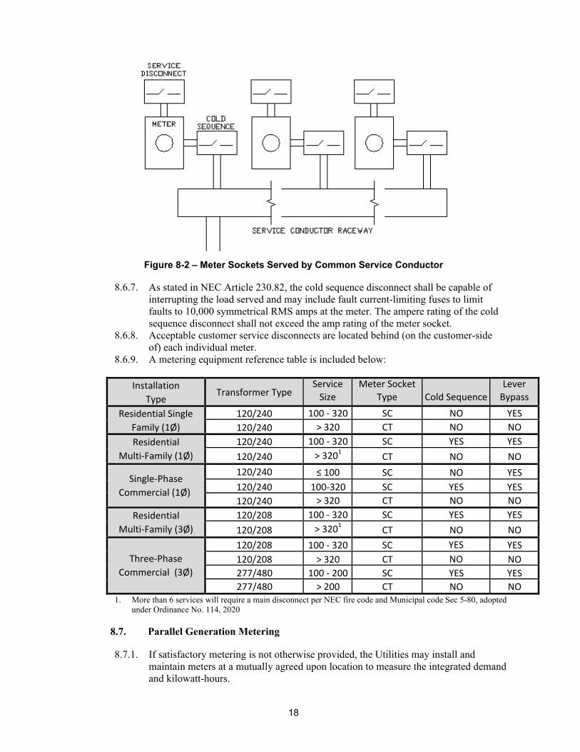
8.6.6. Acceptable cold sequence disconnects include a load-make/load-break safety or pullout switch and shall be ahead of (on the utility source-side of) each individual meter as shown in Figure 8-2. In cases where multiple commercial meter sockets are part of a commercially manufactured unit, it is acceptable to have a single main disconnect acting as a cold sequence/main disconnect. In these cases, each individual meter socket shall have a service disconnect (Figure 8-1).
Figure 8-1 – Ganged Meter Socket Cold Sequence Metering
18
Figure 8-2 – Meter Sockets Served by Common Service Conductor
8.6.7. As stated in NEC Article 230.82, the cold sequence disconnect shall be capable of
interrupting the load served and may include fault current-limiting fuses to limit faults to 10,000 symmetrical RMS amps at the meter. The ampere rating of the cold sequence disconnect shall not exceed the amp rating of the meter socket.
8.6.8. Acceptable customer service disconnects are located behind (on the customer-side of) each individual meter.
8.6.9. A metering equipment reference table is included below:
Installation
Type Transformer Type
Service
Size
Meter Socket
Type Cold Sequence
Lever
Bypass
Residential Single
Family (1Ø)
120/240 100 ‐ 320 SC NO YES
120/240 > 320 CT NO NO
Residential
Multi‐Family (1Ø)
120/240 100 ‐ 320 SC YES YES
120/240 > 3201 CT NO NO
Single‐Phase
Commercial (1Ø)
120/240 ≤ 100 SC NO YES
120/240 100‐320 SC YES YES
120/240 > 320 CT NO NO
Residential
Multi‐Family (3Ø)
120/208 100 ‐ 320 SC YES YES
120/208 > 3201 CT NO NO
Three‐Phase
Commercial (3Ø)
120/208 100 ‐ 320 SC YES YES
120/208 > 320 CT NO NO
277/480 100 ‐ 200 SC YES YES
277/480 > 200 CT NO NO 1. More than 6 services will require a main disconnect per NEC fire code and Municipal code Sec 5-80, adopted
under Ordinance No. 114, 2020
8.7. Parallel Generation Metering
8.7.1. If satisfactory metering is not otherwise provided, the Utilities may install and maintain meters at a mutually agreed upon location to measure the integrated demand and kilowatt-hours.

19
8.7.2. If the Operator sells to a purchasing utility, such metering shall be approved by the Utilities and PRPA and shall record and indicate the integrated demand as determined by the Utilities and shall measure kilowatt-hours.
8.7.3. Meters for measure of reactive volt-ampere hours may be required by the Utilities if deemed appropriate.
8.7.4. All meter equipment, installation, ownership and administration costs thereof shall be borne by Operator, including costs incurred by the Utilities for inspecting and testing such equipment.
8.7.5. All billing meters used to determine the billing of sales to a purchasing utility shall be sealed. Seals shall only be broken by Utilities personnel for the purposes of meter testing, inspection, adjustment, or other maintenance.
8.7.6. The Utilities shall, at the Operator's expense, inspect and test all meters upon their installation and thereafter as determined necessary by Utilities.
8.7.7. If requested to do so by the Operator or the purchasing utility, the Utilities shall inspect or test a meter more frequently than the standard Utilities practice, but the expense of such inspection or test shall be borne by the Operator.
8.7.8. All billing meters shall be installed and operated in accordance with the terms and conditions of PRPA and the purchasing utility.
8.8. Restrictions on Master Metering
8.8.1. For the purposes in this document, a master meter is defined as one meter feeding
multiple premises (occupancies) in the same building or complex of buildings. 8.8.2. Master metering is not available for new or remodeled residential buildings with
more than one (1) dwelling unit unless authorized by the Utilities Executive Director. Exceptions may include affordable or assisted living and other similar purposes. Contact Utilities Electric Project Engineering for a variance form.
9. Construction Coordination Sequence
9.1. General
9.1.1. Construction coordination and scheduling is the responsibility of the developer and owner/builder. To ensure maximum economy in construction, the sequence of installation of utilities, streets, driveways, sidewalks, etc., must be coordinated with the Utilities.
9.1.2. Increased construction costs incurred by the Utilities due to the lack of economic scheduling or construction coordination will be charged to the developer or owner/builder.
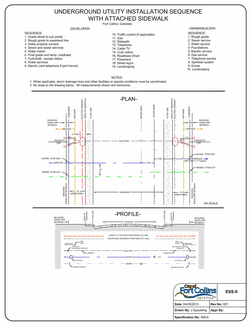
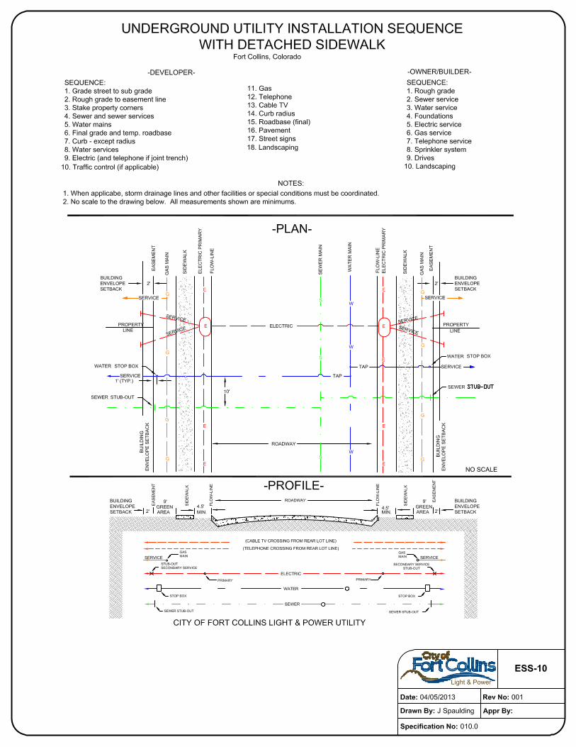
9.1.3. In general, underground utilities should be installed from deepest to shallowest, i.e. the deepest utility should be installed first, the second deepest second, etc.
9.1.4. The underground utility installation sequence diagram included herein illustrates the typical construction plan and profile, along with typical developer and owner/builder sequence steps. This diagram is provided as a guide to assist the developer and the owner/builder. Actual construction sequences must be coordinated with the Utilities on a project by project basis.
9.1.5. Changes or additions to the electric system due to development deviations will be made at the expense of the developer or owner. A development deviation is any variation from the prescribed sequence of development that increases the cost of construction for the Utilities.
9.2. Prerequisite to Construction

20
9.2.1. The developer shall grant easements for the installation of the Utilities’ facilities that accommodate state and local facility separation requirements.
9.2.2. All lot corners pertaining to the underground system must be staked and all final grading on the service lines and easements completed before work will be started. Curb (except for radius sections), gutter and final grade, adjacent to and 15 feet from the property side of the curb, must be completed prior to the installation of the electric facilities.
9.2.3. Concrete curb and sidewalks must be cured a minimum of 7 days to prevent damage thereto.
9.3. Street Crossing Option
9.3.1. Upon the approval of the Utilities, a developer may install conduits at street crossings. This option expedites the development process when street paving is scheduled before the underground electrical system can be installed.
9.3.2. The Utilities will specify the locations of such crossings and provide all materials to the developer.
9.3.3. All crossings must be inspected and approved by the Utilities. 9.3.4. The developer/owner/agent is responsible for the cost and repair or replacement of
damaged or unusable conduit in street crossings provided for installation of electric and joint use facilities.
9.4. Trenching Option
9.4.1. At the discretion of the Utilities, the developer or owner may be required to furnish
all necessary trenches, excavations and backfills to meet the requirements established by the Utilities for the underground electric system.
9.4.2. All trenches dug by the developer or owner will be inspected and approved by the Utilities prior to the installation of conduits and conductors. The Utilities will, in these cases, approve the backfill material and installation. If the excavated material contains rock, the developer will be required to supply proper backfilling material.
9.4.3. It is the developer or owner's responsibility to coordinate all work, including the inspection of trenches and backfill. The Utilities reserves the right to test compaction or depth at the cost of the developer or owner.
9.5. Joint Use Construction
9.5.1. In cases where the electric trench is to be used for the installation of communications
or other utility facilities, plans shall be made with the Utilities for inclusion in the final electrical design prior to the developer's request for scheduling and a minimum of two weeks prior to the date that electric construction is to begin.
9.5.2. The initial planning, coordination and implementation of a joint use agreement with the Utilities shall be the responsibility of the developer, owner and or third-party utility desiring joint use trench.
9.5.3. The Utilities will not offer joint use to those who have not completed the coordination of their planning with the joint use parties.
9.5.4. Joint use costs will be charged to the owner/developer or third-party utility to recover engineering service, construction, installation of facilities, maintenance and administrative costs.
10. Easements
21
10.1.1. By making application for electric service, the customer agrees to grant or arrange for an easement on the customer’s property for the installation, operation and maintenance of electric lines, wires and other equipment of the Utilities necessary to render service to the customer.
10.1.2. When requested by the Utilities, the customer shall without expense to the Utilities make or procure a conveyance to the Utilities of satisfactory easements across the property owned or controlled by the customer for the Utilities’ lines or extensions thereof necessary or incidental to the furnishing of service to the customer.
10.1.3. If such installation must be made on or over the property of a third party, it shall be the responsibility of the customer to obtain an easement for the Utilities from the third party before the installation can be made and service rendered.
10.1.4. If, after service is originally rendered, the customer’s property is divided in such a manner that part of the property no longer has access to the right-of-way of the Utilities’ distribution system, the customer shall reserve an easement for the benefit of the Utilities so that the Utilities may render electric service to such isolated parcel.
10.1.5. In the case where an easement has been granted and electric distribution facilities have been installed, the parties seeking to have such easement changed shall pay the Utilities the actual cost for relocation of the electric distribution facilities and shall provide the necessary alternative rights-of-way.
11. Interconnection of Qualifying Parallel Generation Facilities
11.1. Application
11.1.1. Any Qualifying Facility (see definitions in Municipal Code Section 26-391) may interconnect with, operate in parallel with, or transmit over the Utilities’ facilities as provided herein. Each Qualifying Facility shall make application to the Utilities and obtain written approval of entrance location, number of phases, voltage number and types of meters, and underground or overhead connection before making commitments to equipment purchases and before the start of construction.
11.1.2. The Operator of each Qualifying Facility shall obtain a Permit-to-Operate from Utilities prior to final parallel connection and operation with the Utilities’ electric distribution system.
11.2. Initial Start-Up
11.2.1. Each Qualifying Facility shall notify the Utilities of the initial energizing and start-up test of the Qualifying Facility's generating equipment. The Utilities shall have the right to be present at such test.
11.2.2. Notice of such initial energizing and start-up test shall be given by the Qualifying Facility to the Utilities at a reasonable time prior to such event.
11.2.3. No Qualifying Facility shall operate in parallel with the Utilities’ system until all relays, controls and other devices, as required by the Utilities, have been installed and all safety standards and testing requirements have been met. Upon satisfactory inspection of interconnection facilities, final written approval to operate shall be provided by the Utilities in the form of a Permit-to-Operate.
11.3. Facility Design and Construction
11.3.1. The Operator shall design, construct, install, own, operate and maintain the Facility and all equipment needed to generate and deliver energy and capacity except for any special facilities constructed, installed and maintained by the Utilities.

22
11.3.2. The Operator shall construct, install, own and maintain interconnection facilities and system protection facilities as required for the Utilities to provide for system capacity, safety and operation.
11.3.3. The Facility shall meet all requirements of applicable codes and all standards of prudent electrical practice and the requirements of the Utilities. Such requirements may include locks, seals, breakers, protective relaying, automatic synchrometers and disconnecting devices.
11.3.4. The Qualifying Facility operator shall submit all of the Facility's specifications to the Utilities for review and approval prior to connecting the Facility to the Utilities system. The Utilities’ review of the Operator's specifications shall not be construed as confirming nor endorsing the design, or as any warranty of safety, durability or reliability of the Facility.
11.3.5. The Operator agrees that, upon demand of the Utilities, the Operator shall change its Facility to comply with changing requirements of the Utilities’ system.
11.4. Facility Operation and Maintenance
11.4.1. The Operator shall operate and maintain its Facility according to prudent electrical
practices and shall generate or otherwise supply such reactive power necessary to maintain a 95% power factor to maintain voltage levels and reactive support to the system.
11.4.2. If the Operator is unable or unwilling to provide such reactive power, the Utilities may do so at the Operator's expense or may disconnect the Facility without notice.
11.4.3. Facility operation shall be such that its electrical operation parameters are within the Utilities’ system operating parameters at the point of Facility interconnection with the Utilities.
11.5. Changes in Facility or Capacity Rating
11.5.1. The Operator shall advise the Utilities and PRPA of any proposed changes in its
Facility or its capacity rating prior to making such changes. 11.5.2. Such changes shall be made in accordance with the City Code and these service
standards as if the changes were a new Facility. 12. Working Adjacent To Overhead Lines
12.1.1. Any person, customer, business, or other party working within ten (10) feet of
overhead power lines carrying more than 600 volts shall provide 72 hours of notice to the Utilities of such work.
12.1.2. The Utilities shall coordinate the efforts to cover up or in some manner to make such lines safe for the work or activity.
12.1.3. The customer, person, business or party shall pay all costs associated with making such lines safe.
12.1.4. Failure to notify the Utilities 72 hours in advance of any activity within 10 feet of overhead lines, shall relieve the Utilities of all responsibility or liability for accidents, injuries or damages arising through or from such activities.
13. Locate Policy
13.1.1. Fort Collins Utilities facilities shall only be located by Fort Collins Utilities Locating personnel. Colorado State laws pertaining to location of facilities shall be followed when any parties are performing any construction or excavation.
14. Contractor Access to Transformer Secondary Compartments

23
14.1.1. The Utilities will not provide access to energized transformer compartments. All
contractor work performed in the secondary compartment of the transformer shall be completed while the transformer is de-energized in accordance with Fort Collins Utilities Light & Power Safety Manual. In order to schedule the de-energization of the transformer for contractor-requested work, contractors are required to provide 72 hours of notice to the Utilities.
15. Other Rules and Regulations
These standards are intended to supplement and not alter applicable sections of the Municipal Code. If a conflict does occur, the Municipal Code shall apply.
16. Design Drawings
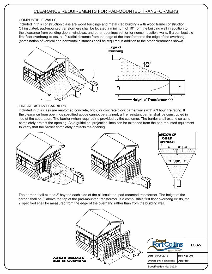
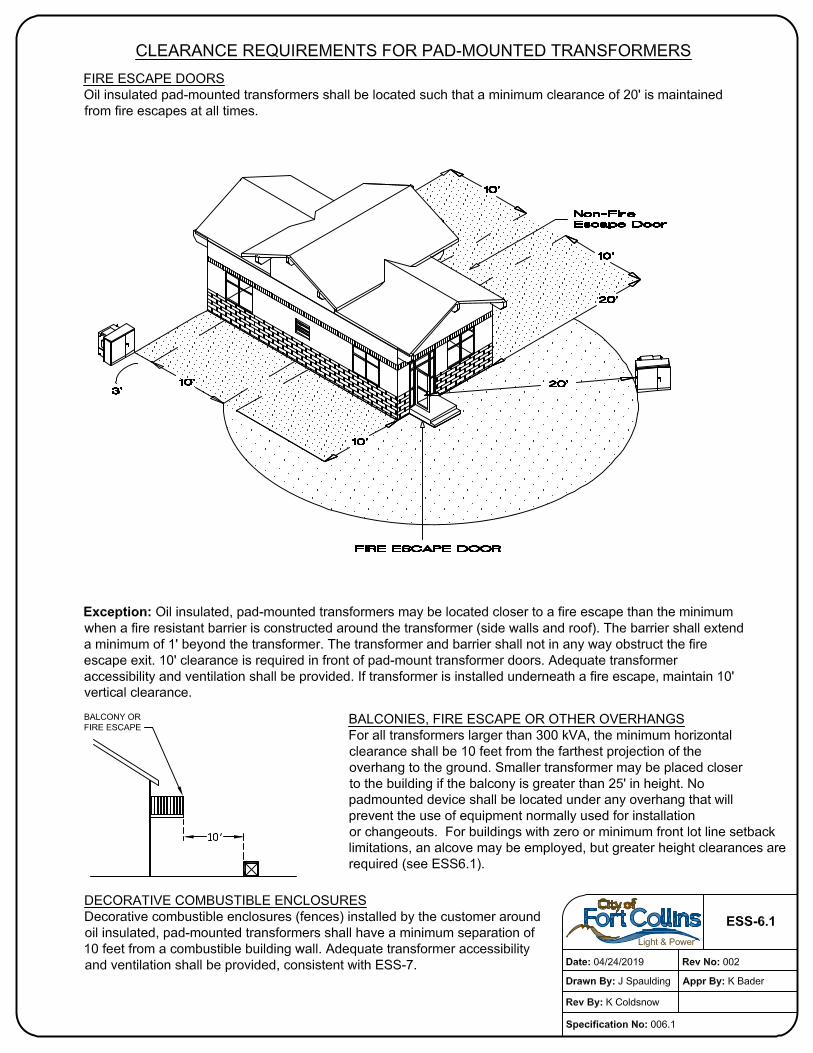
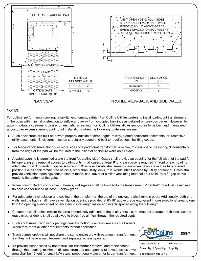
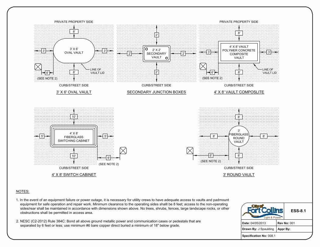
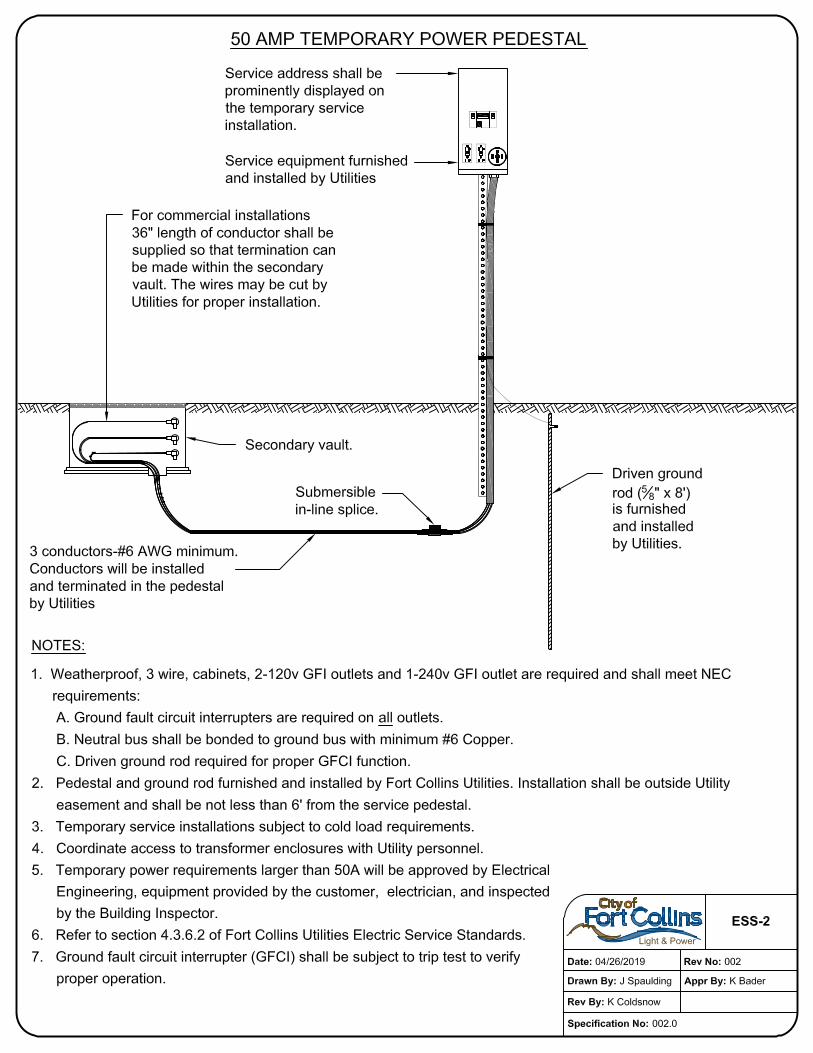
16.1.1. Design drawings identified below are attached as appendices to this document and marked with the identified title. A description of the requirements included in the drawing is included. These design drawings are intended to either visually enhance requirements already discussed or to establish requirements that are referenced in earlier sections of the Electric Service Standards. ESS-1 shows requirements for an underground service meter installation. ESS-2 shows requirements for unmetered temporary electric service installations. ESS-3 shows requirements for metered temporary electric service installations. ESS-4 shows clearance requirements for padmounted transformers from buildings, windows, doors, etc. ESS-5 shows clearance requirements for padmounted transformers from combustible walls, fire-resistant barriers, etc. ESS-6.1 shows clearance requirements for padmounted transformers from fire escape doors, decorative combustible enclosures, etc. ESS-6.2 Shows clearances for transformers placed in alcoves ESS-7 shows clearance requirements for oil filled equipment from aesthetic screening enclosures. ESS-8.1 and ESS-8.2 show access and work clearance requirements for vaults and padmounted equipment. ESS-9 shows the underground utility installation sequence with attached sidewalk. ESS-10 shows the underground utility installation sequence with detached sidewalk.
17. Variance from Electric Service Standards
17.1.1. Whenever there are practical difficulties involved in carrying out the requirements
described in the design drawings referenced in Section 16 of the Electric Service Standards, a Utilities official shall have the authority to grant modifications for individual cases, upon application of the developer, provided such Utilities official finds that the proposed design plan is in compliance with the intent and purpose of the Electric Service Standards and that such modification does not lessen health, accessibility, life and fire safety, or reliability. The details of action granting or denying modification requests shall be recorded and entered in the Utilities department files. Contact Utilities Electric Project Engineering for a variance form.
18. Appeals

24
18.1.1. Appeals of decisions made by the Utilities official relative to the application and
interpretation of the requirements contained in the design drawings referenced at Section 16 of the Electric Service Standards shall be as set forth in Chapter 26 of the City Code. When a developer desires relief from a decision of the Utilities official, such developer must first apply for a modification under Section 17 above and receive a notice of decision on that request from the Utilities official.

25
Glossary
Building Site Charges - Charges for installing electric service lines from the street to the residential meter or commercial transformer. Off-site facilities (kVA load) charge, primary service charge, and secondary service charge are collectively referred to as "building site charges."
Cold Sequence Disconnect – A disconnect installed on the utility source-side of the metering equipment capable of interrupting the load served.
Commercial service construction – Any service used primarily for the operation of a business or, regardless of use or purpose, requiring over 200 amps or three phase is a commercial or industrial service.
Development Charges - Charges for providing primary electric service to the lot corner of the site, including the cost of streetlight construction. Off-site facilities, primary charge and streetlight charge are collectively referred to as "development charges."
Excavation - Any operation in which earth is moved or removed by means of any tools, equipment or explosives and includes, but is not limited to, auguring, backfilling, ditching, drilling, grading, plowing-in, pulling-in, ripping, scraping, trenching and tunneling.
Off Site Facilities - Delivers electric power from main substations to subdivisions and load areas.
Off Site Facilities Charge - Cost to bring primary electric power from main substations to subdivisions and load areas.
Point of Delivery - That point beyond which the customer is responsible for installation, maintenance and field locating of electrical equipment. Except as otherwise specified in these Electric Service Standards, the point of delivery for residential construction applications is the source side of the electric meter socket termination lugs. For commercial and industrial service applications, the point of delivery is the secondary lugs or spades of the distribution transformer, or, if existing, it is the nearest junction box/vault installed by Utilities serving the load at issue. For primary metered customers, the point of delivery is the source-side terminations in customer-owned switchgear or as otherwise designated by Utilities.
Primary Charge - Cost to bring primary electric power at primary voltage from the subdivision boundary to the internal loads in the subdivision.
Primary Electric Service - All cable, enclosures, switches and associated apparatus necessary to provide primary service to the transformers or primary bus from the primary feeder.
Primary Feeder - Delivers electric power at primary voltage to the subdivision or individual load from the off-site facilities.
Primary Service Charge - Cost to bring primary voltage electric cable to padmounted transformers or building vaults on customer's premises.
Redevelopment - New construction on a site on which development charges have not previously been paid, or as determined by the Utilities.
Residential service construction- Any single phase service for the exclusive use of the individual customer for domestic purposes. Any service application requiring over 200 amps, or three phase, regardless of purpose, is a commercial or industrial service. Secondary Electric Service - Electric distribution service cables of 600 volts and below
from the transformer to the customer's metering point. Secondary Service Charge - Cost to bring electric distribution service cables of 600 volts
and below from the transformer to the customer's metering point. Streetlight Charge - The charge for the installation of new streetlights. Streetlights are
installed in accordance with the City of Fort Collins' Design Criteria and Standards for Streets. Temporary Service - Temporary service is defined as electric service provided for a short-
term need, such as that service required by such customers as special events or festivals, construction contractors, and similar enterprises.
UL - Underwriters' Laboratories, Inc. Utilities - The City of Fort Collins Utilities (the Utilities).
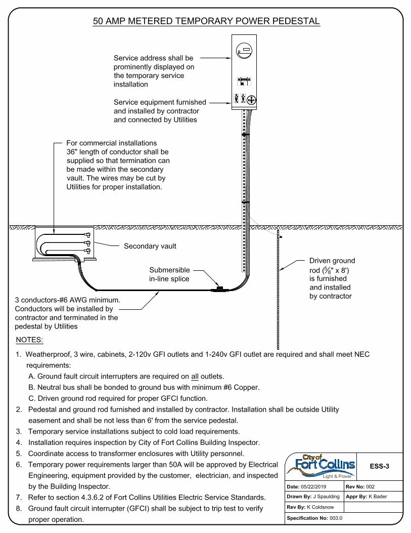
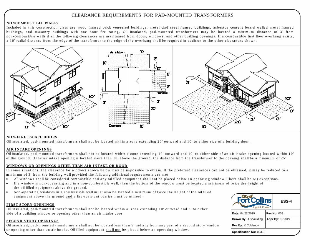
AIR INTAKE OPENINGS
Oil insulated, pad-mounted transformers shall not be located within a zone extending 10' outward and 10' to either side of an air intake opening located within 10'
of the ground. If the air intake opening is located more than 10' above the ground, the distance from the transformer to the opening shall be a minimum of 25'
NON-FIRE ESCAPE DOORS
Oil insulated, pad-mounted transformers shall not be located within a zone extending 20' outward and 10' to either side of a building door
NONCOMBUSTIBLE WALLS
Included in this construction class are wood framed brick veneered buildings, metal clad steel framed buildings, asbestos cement board walled metal framed
buildings, and masonry buildings with one hour fire rating. Oil insulated, pad-mounted transformers may be located a minimum distance of 3' from
non-combustible walls if all the following clearances are maintained from doors, windows, and other building openings. If a combustible first floor overhang exists,
a 10' radial distance from the edge of the transformer to the edge of the overhang shall be required in addition to the other clearances shown.
WINDOWS OR OPENINGS OTHER THAN AIR INTAKE OR DOOR
In some situations, the clearance for windows shown below may be impossible to obtain. If the preferred clearances can not be obtained, it may be reduced to a
minimum of 3' from the building wall provided the following additional requirements are met:
All windows shall be considered combustible and any oil filled equipment shall not be placed below an operating window. There shall be NO exceptions.
If a window is non-operating and in a non-combustible wall, then the bottom of the window must be located a minimum of twice the height of
the oil filled equipment above the ground.
Non-operating windows in a combustible wall must also be located a minimum of twice the height of the oil filled
equipment above the ground and a fire-resistant barrier must be utilized.
FIRST STORY OPENINGS
Oil insulated, pad-mounted transformers shall not be located within a zone extending 10' outward and 3' to either
side of a building window or opening other than an air intake door.
SECOND STORY OPENINGS
Oil insulated, pad-mounted transformers shall not be located less than 5' radially from any part of a second story window
or opening other than an air intake. Oil filled equipment shall not be placed below an operating window.
CLEARANCE REQUIREMENTS FOR PAD-MOUNTED TRANSFORMERS
Light & Power
Date: 04/22/2019 Rev No: 003
Drawn By: J Spaulding Appr By: K Bader
ESS-4
Specification No: 003.0
Rev By: K Coldsnow