Embed Size (px)
Citation preview
Patented
ERD ElEctRic
RoD-StylE ActuAtoR
LINEAR SOLUTIONS MADE EASYLINEAR SOLUTIONS MADE EASY
S E R V I C E
AMS
USDA
AG
RIC
ULT
URAL M A
RK
ET
I NG
United S
tates Department of Agriculture
Accepted Equipment
erd_2
1-800-328-2174 www.tolomatic.com
ERD – Electric Rod-Style Actuator
PneumaticReplacement Wash-down
Stainless Steel, IP69k
Wash-down / High ForceStainless Steel, IP69k
GuidedOPTION
PneumaticReplacement Wash-down
Stainless Steel, IP69k
Wash-down / High ForceStainless Steel, IP69k
GuidedOPTION
ERD06
ERD10
ERD15
ERD20
ERD06
ERD10
ERD15
ERD20
ERD25
ERD30
ERD20IP69k ERD15
IP69kERD10IP67
ERD06
ERD10
ERD15
ERD20
ERD06
ERD10
ERD15
ERD20
ERD25
ERD30
ERD20IP69k ERD15
IP69kERD10IP67
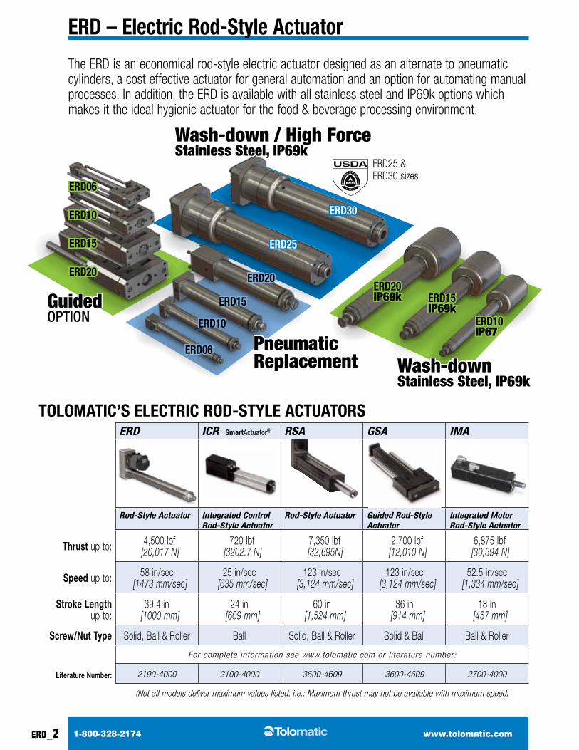
the eRd is an economical rod-style electric actuator designed as an alternate to pneumatic cylinders, a cost effective actuator for general automation and an option for automating manual processes. In addition, the eRd is available with all stainless steel and IP69k options which makes it the ideal hygienic actuator for the food & beverage processing environment.
tolomAtic’S ElEctRic RoD-StylE ActuAtoRSERD ICR SmartActuator® RSA GSA IMA
Rod-Style Actuator Integrated Control Rod-Style Actuator
Rod-Style Actuator Guided Rod-Style Actuator
Integrated Motor Rod-Style Actuator
Thrust up to: 4,500 lbf [20,017 N]
720 lbf [3202.7 N]
7,350 lbf [32,695N]
2,700 lbf [12,010 N]
6,875 lbf [30,594 N]
Speed up to: 58 in/sec [1473 mm/sec]
25 in/sec [635 mm/sec]
123 in/sec [3,124 mm/sec]
123 in/sec [3,124 mm/sec]
52.5 in/sec [1,334 mm/sec]
Stroke Length up to:
39.4 in [1000 mm]
24 in [609 mm]
60 in [1,524 mm]
36 in [914 mm]
18 in [457 mm]
Screw/Nut Type Solid, Ball & Roller Ball Solid, Ball & Roller Solid & Ball Ball & Roller
For complete information see www.tolomatic.com or literature number:
Literature Number: 2190-4000 2100-4000 3600-4609 3600-4609 2700-4000
(Not all models deliver maximum values listed, i.e.: Maximum thrust may not be available with maximum speed)
S E R V I C E
AMS
USDA
AG
RIC
ULT
URAL M A
RK
ET
I NG
United S
tates Department of Agriculture
Accepted Equipment
eRd25 & eRd30 sizes
erd_3
1-800-328-2174 www.tolomatic.com
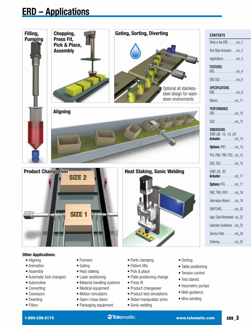
ERD – Applications
• Aligning• Animation• Assembly• Automatic tool changers• Automotive• Converting• Conveyors• Diverting• Fillers
• Formers• Gating• Heat staking• Laser positioning• Material handling systems• Medical equipment• Motion simulators• Open / close doors• Packaging equipment
• Parts clamping• Patient lifts• Pick & place• Plate positioning change• Press fit• Product changeover• Product test simulations• Robot manipulator arms• Sonic welding
• Sorting
• Table positioning
• Tension control
• Test stands
• Volumetric pumps
• Web guidance
• Wire winding
other Applications:
Gating, Sorting, Diverting
Product change over Heat Staking, Sonic Welding
coNtENtS
What is the ERD . . . . . .erd_2
Rod-Style Actuators . . .erd_2
applications . . . . . . . . .erd_3
FEATURES eRd . . . . . . . . . . . . . . .erd_4
ERD SS2 . . . . . . . . . . .erd_6
SPECIFICATIONS eRd . . . . . . . . . . . . . . .erd_8
Motors . . . . . . . . . . . .erd_11
PERFORmANCE eRd . . . . . . . . . . . . . .erd_10
GD2. . . . . . . . . . . . . .erd_13
DImENSIONS ERD-06, 10, 15, 20 Actuator . . . . . . . . . .erd_14
options: IP67 . . . . . .erd_14
FFG, FM2, TRR, PCD. .erd_15
GD2, SS2 . . . . . . . . . .erd_16
ERD-25, 30 Actuator . . . . . . . . . .erd_17
options: FFG . . . . . .erd_17
FM2, Trr, HYG1 . . . . .erd_18
Alternative Motors . . .erd_19
SWiTCHES . . . . . . . . .erd_20
Appl. Data Worksheet erd_22
Selection Guidelines . .erd_23
Service Parts . . . . . . .erd_24
Ordering. . . . . . . . . . .erd_25
Optional all stainless-steel design for wash-down environments
chopping, Press Fit, Pick & Place, Assembly
Filling, Pumping
Aligning
erd_4
1-800-328-2174 www.tolomatic.com
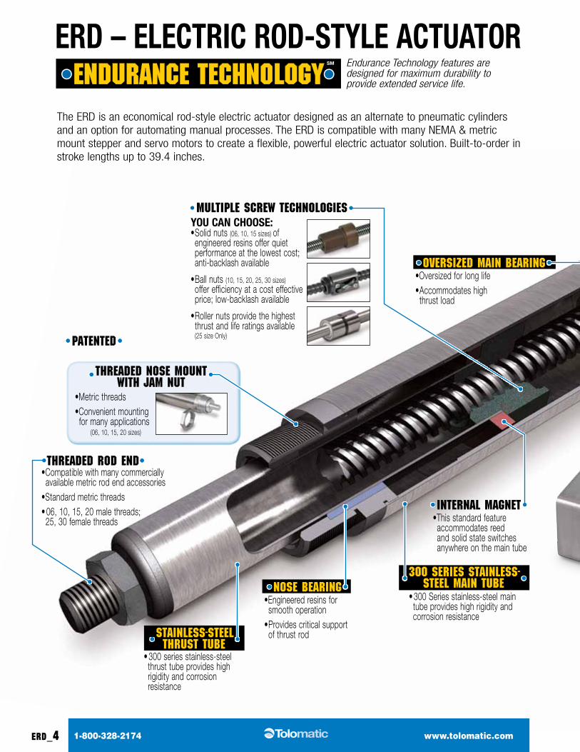
ERD – ElEctRic RoD-StylE ActuAtoR
•This standard feature accommodates reed and solid state switches anywhere on the main tube
•Compatible with many commercially available metric rod end accessories
•Standard metric threads• 06, 10, 15, 20 male threads;
25, 30 female threads
•Metric threads•Convenient mounting
for many applications(06, 10, 15, 20 sizes)
•Oversized for long life• Accommodates high
thrust load
•Engineered resins for smooth operation
• Provides critical support of thrust rod
Endurance Technology features are designed for maximum durability to provide extended service life.
Oversized Main Bearing
nOse Bearing
Patented
internal Magnet
threaded rOd end
threaded nOse MOunt With JaM nut
• 300 Series stainless-steel main tube provides high rigidity and corrosion resistance
• 300 series stainless-steel thrust tube provides high rigidity and corrosion resistance
300 series stainless- steel Main tuBe
stainless-steel thrust tuBe
the eRd is an economical rod-style electric actuator designed as an alternate to pneumatic cylinders and an option for automating manual processes. The ERD is compatible with many NEMA & metric mount stepper and servo motors to create a flexible, powerful electric actuator solution. Built-to-order in stroke lengths up to 39.4 inches.
you cAN cHooSE:• Solid nuts (06, 10, 15 sizes)
of engineered resins offer quiet performance at the lowest cost; anti-backlash available
• Ball nuts (10, 15, 20, 25, 30 sizes)
offer efficiency at a cost effective price; low-backlash available
• Roller nuts provide the highest thrust and life ratings available (25 size Only)
MultiPle sCreW teChnOlOgies
erd_5
1-800-328-2174 www.tolomatic.com
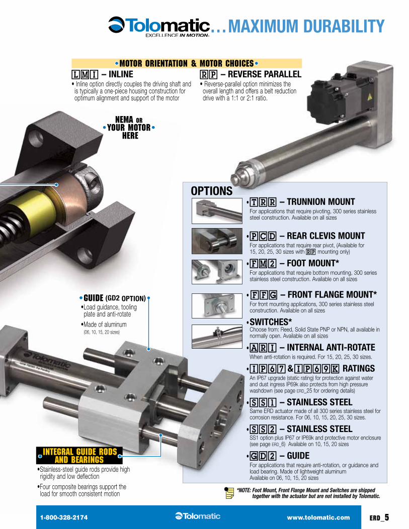
ERD – ElEctRic RoD-StylE ActuAtoR … mAXimum DuRABility
• TRR – tRuNNioN mouNt For applications that require pivoting, 300 series stainless
steel construction. Available on all sizes
• PCD – REAR clEviS mouNt For applications that require rear pivot, (Available for
15, 20, 25, 30 sizes with RP mounting only)
• FM2 – Foot mouNt* For applications that require bottom mounting, 300 series
stainless steel construction. Available on all sizes
• FFG – FRoNt FlANGE mouNt* For front mounting applications, 300 series stainless steel
construction. Available on all sizes
• SWitcHES* Choose from: Reed, Solid State PNP or NPN, all available in
normally open. Available on all sizes
• ARI – iNtERNAl ANti-RotAtE When anti-rotation is required. For 15, 20, 25, 30 sizes.
• IP67 & IP69k RAtiNGS An IP67 upgrade (static rating) for protection against water
and dust ingress IP69k also protects from high pressure washdown (see page erd_25 for ordering details)
• SS1 – StAiNlESS StEEl Same ERD actuator made of all 300 series stainless steel for
corrosion resistance. For 06, 10, 15, 20, 25, 30 sizes.
• SS2 – StAiNlESS StEEl SS1 option plus IP67 or IP69k and protective motor enclosure
(see page erd_6) Available on 10, 15, 20 sizes
• GD2 – GuiDE For applications that require anti-rotation, or guidance and
load bearing. Made of lightweight aluminum Available on 06, 10, 15, 20 sizes
oPtioNS
*NOTE: Foot Mount, Front Flange Mount and Switches are shipped
together with the actuator but are not installed by Tolomatic.
•Load guidance, tooling plate and anti-rotate
•Made of aluminum (06, 10, 15, 20 sizes)
guide (GD2 oPtioN)
MOtOr OrientatiOn & MOtOr ChOiCes LMI – iNliNE• Inline option directly couples the driving shaft and
is typically a one-piece housing construction for optimum alignment and support of the motor
RP – REvERSE PARAllEl• Reverse-parallel option minimizes the
overall length and offers a belt reduction drive with a 1:1 or 2:1 ratio.
neMa Or YOur MOtOr
here
integral guide rOds and Bearings•Stainless-steel guide rods provide high
rigidity and low deflection•Four composite bearings support the
load for smooth consistent motion
erd_6
1-800-328-2174 www.tolomatic.com
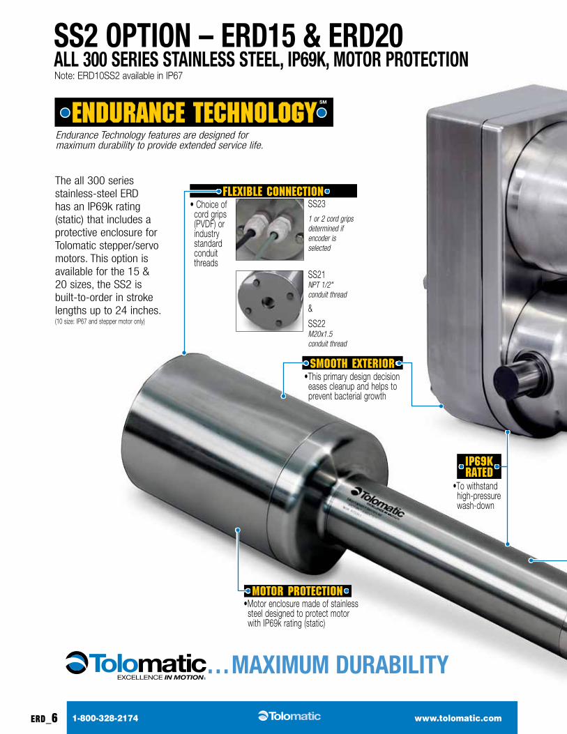
SS2 oPtioN – ERD15 & ERD20 All 300 SERiES StAiNlESS StEEl, iP69k, motoR PRotEctioN
… mAXimum DuRABility
the all 300 series stainless-steel eRd has an IP69k rating (static) that includes a protective enclosure for Tolomatic stepper/servo motors. this option is available for the 15 & 20 sizes, the SS2 is built-to-order in stroke lengths up to 24 inches. (10 size: IP67 and stepper motor only)
• Choice of cord grips (PVDF) or industry standard conduit threads
•Motor enclosure made of stainless steel designed to protect motor with IP69k rating (static)
•To withstand high-pressure wash-down
•This primary design decision eases cleanup and helps to prevent bacterial growth
MOtOr PrOteCtiOn
iP69k rated
sMOOth exteriOr
FlexiBle COnneCtiOn SS231 or 2 cord grips determined if encoder is selected
SS21NPT 1/2" conduit thread
&
SS22M20x1.5 conduit thread
Endurance Technology features are designed for maximum durability to provide extended service life.
Note: ERD10SS2 available in IP67
erd_7
1-800-328-2174 www.tolomatic.com
SS2 oPtioN – ERD15 & ERD20 All 300 SERiES StAiNlESS StEEl, iP69k, motoR PRotEctioN
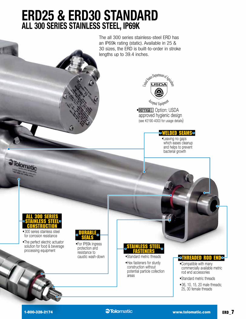
ERD25 & ERD30 StANDARD All 300 SERiES StAiNlESS StEEl, iP69k
the all 300 series stainless-steel eRd has an IP69k rating (static). available in 25 & 30 sizes, the eRd is built-to-order in stroke lengths up to 39.4 inches.
•Leaving no gaps which eases cleanup and helps to prevent bacterial growth
•Standard metric threads•Hex fasteners for sturdy
construction without potential particle collection areas
•HYG1 Option: USDA approved hygienic design (see #2190-4003 for usage details)
•For IP69k ingress pro tection and resistance to caustic wash-down
duraBle seals
stainless steel Fasteners
Welded seaMs
• 300 series stainless steel for corrosion resistance
•The perfect electric actuator solution for food & beverage processing equipment
all 300 series stainless steel COnstruCtiOn
S E R V I C E
AMS
USDA
AG
RIC
ULT
URAL M A
RK
ET
I NG
United S
tates Department of Agriculture
Accepted Equipment
•Compatible with many commercially available metric rod end accessories
•Standard metric threads• 06, 10, 15, 20 male threads;
25, 30 female threads
threaded rOd end
ERD
SiZE
ScRE
W
DiA.
mAX
imum
St
RokE
*
ScRE
W
coDE
lEAD lEA
D
Accu
RAcy
BAck
lASH
mAX
imum
tH
RuSt
DyNA
mic
lo
AD
RAti
NG
iNERtiA WEiGHtWEiGHt
(GD2 adder)lmi RP lmiRP
(Al)RP
(SS)(SS2
adder)Base Base Per Inch Per Inch Base Base Base Base Base Per Inch
in in in/rev in/ft in lbf lbf lb-in2 lb-in2 lb-in2 lb lb lb lb lb lb lb
06 0.250 8SN02 0.500
0.005
0.007
20 na 0.0018 – 0.0001 0.035 0.263 – – – 0.579 0.027SN04 0.250SN16 0.063
100.375
10
SN01 1.0000.007 40 na 0.0022 – 0.0006 0.069 0.411 – –
2.280 1.028 0.061SN02 0.500SN05 0.200
0.472 BNM05 0.197 0.004 0.005 100 240 0.0040 – 0.0014 0.087 0.607 – –
150.500 12
SN01 1.000 0.0060.007 75 na 0.0104 0.2101 0.0017 0.126 1.079 4.230 7.761
5.771 2.297 0.095SN02 0.500 0.005SN05 0.200 0.006
0.630 24BNM05 0.197
0.004 0.005 200450
0.0178 0.2208 0.0044 0.159 1.170 4.230 7.761BNM10 0.394 400
20 0.984 24BNM05 0.197
0.004 0.005 500 900 0.0628 0.4102 0.0263 0.325 7.575 23 FRM 5.610 34 FRM 6.050
9.030 9.448 – 6.455 0.256
BNM10 0.394
ERD
SiZE
ScRE
W
DiA.
mAX
imum
St
RokE
*
ScRE
W
coDE
lEAD lEA
D
Accu
RAcy
BAck
lASH
mAX
imum
tH
RuSt
DyNA
mic
lo
AD
RAti
NG
iNERtiA WEiGHt
lmi RPlmi (Al)
lmi (SS)
RP (Al)
RP (SS)
Base Base Per Inch Base Base Base Base Per Inch
in in in/rev in/ft in lbf lbf lb-in2 lb-in2 lb-in2 lb lb lb lb lb
25
1.000
39.4
Bn01 1.0000.004
0.002 711 25000.8634 7.7486 0.0277
24.46 31.77 35.13 53.850.87Bn02 0.500
0.0151423 5418 24.41
31.7335.08
53.81Bn04 0.250 2846 5238 24.42 35.09
0.984BNM05 0.197
0.002 0.0042000 3395
0.8550 7.7402 0.026024.03 31.34 34.70 53.42
0.86BNM10 0.394 1750 3372 24.47 31.75 35.14 53.83BNM25 0.984 0.004 0.005 700 2537 24.22 31.50 34.89 53.58
0.787 16Rn05 0.197
0.0004 0.00123300 10683
0.7734 7.6586 0.0106 23.98 31.29 34.65 53.37 0.78Rn10 0.394 1500 9210
30
1.500
39.4
Bn04 0.250 0.004 0.015 4500 7143 4.3489 8.4073 0.1401 25.35 32.66 36.02 54.73 1.39
1.575BNM05 0.197
0.0020.004
3000 67144.4929 8.5513 0.1702
26.76 34.07 37.43 56.141.44BNM10 0.394 2950 7476 28.17 35.48 38.84 57.55
BNM20 0.787 0.005 1845 5528 26.27 33.58 36.94 55.65
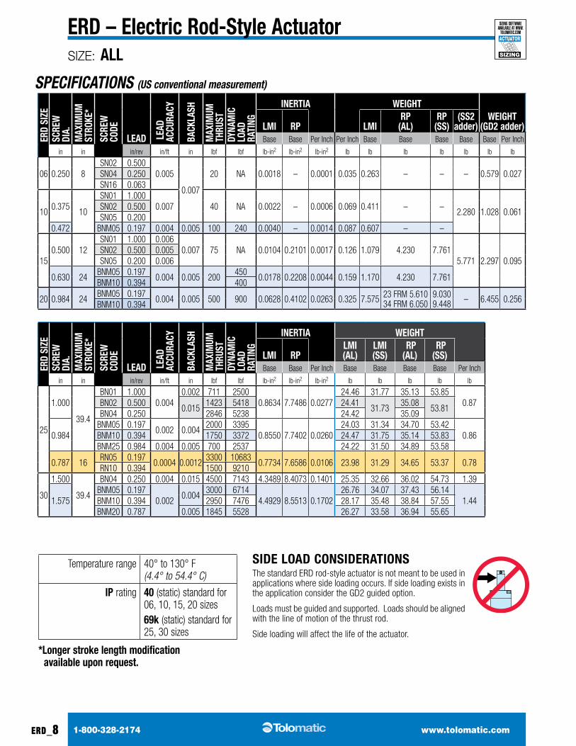
temperature range 40° to 130° F (4.4° to 54.4° C)
iP rating 40 (static) standard for 06, 10, 15, 20 sizes69k (static) standard for 25, 30 sizes
*longer stroke length modification available upon request.
SIZE: ALL
1-800-328-2174 www.tolomatic.comerd_8
ERD – Electric Rod-Style ActuatorSIZING
ACTUATOR
sizing software available at www.
tolomatic.com
SPECIFICATIONS (US conventional measurement)
SiDE loAD coNSiDERAtioNSthe standard eRd rod-style actuator is not meant to be used in applications where side loading occurs. If side loading exists in the application consider the GD2 guided option.
Loads must be guided and supported. Loads should be aligned with the line of motion of the thrust rod.
Side loading will affect the life of the actuator.
ERD
SiZE
ScRE
W
DiA.
mAX
imum
St
RokE
*
ScRE
W
coDE
lEAD lEA
D
Accu
RAcy
BAck
lASH
mAX
imum
tH
RuSt
DyNA
mic
lo
AD
RAti
NG
iNERtiA WEiGHtWEiGHt
(GD2 adder)lmi RP lmiRP
(Al)RP
(SS)(SS2
adder)Base Base Per 25mm Per 25mm Base Base Base Base Base Per 25mm
mm mm mm/rev mm / 300mm mm N N kg-m2 x 10-6 kg-m2 x 10-6 kg-m2 x 10-6 kg kg kg kg kg kg kg
06 6.35 203.2SN02 12.7
0.13
0.18
89 NA 0.53 – 0.03 0.016 0.119 – – – 0.263 0.012SN04 6.35SN16 1.60
109.53
254.0
SN01 25.40.18 188 NA 0.64 – 0.18 0.031 0.186 – –
2.280 0.466 0.028SN02 12.7SN05 5.08
12.00 BNM05 5.00 0.87 0.13 445 1068 1.16 – 0.41 0.039 0.275 – –
1512.70 304.8
SN01 25.4 0.150.18 334 NA 3.04 61.48 0.50 0.057 0.489 1.919 3.520
5.771 1.042 0.043SN02 12.7 0.13SN05 5.08 0.15
16.00 609.6BNM05 5.00
0.87 0.13 8902002
5.21 64.61 1.28 0.072 0.531 1.919 3.520BNM10 10.00 1779
20 25.00 609.6BNM05 5.00
0.87 0.13 2224 4003 18.38 120.04 7.7 0.147 3.436 23 FRM 2.545 34 FRM 2.744
4.096 4.286 – 2.928 0.116
BNM10 10.00
ERD
SiZE
ScRE
W
DiA.
mAX
imum
St
RokE
*
ScRE
W
coDE
lEAD lEA
D
Accu
RAcy
BAck
lASH
mAX
imum
tH
RuSt
DyNA
mic
lo
AD
RAti
NG
iNERtiA WEiGHt
lmi RPlmi (Al)
lmi (SS)
RP (Al)
RP (SS)
Base Base Per 25mm Base Base Base Base Per 25mm
mm mm mm/rev mm / 300mm mm N N kg-m2 x 10-6 kg-m2 x 10-6 kg-m2 x 10-6 kg kg kg kg kg
25
25.40
1000
Bn01 25.400.102 0.05
3163 25002.5298 22.7034 0.0812
11.09 14.41 15.93 24.42
0.39
Bn02 12.70 6330 5418 11.0714.39 15.91 24.41
Bn04 6.35 12660 5238 11.08
25.00BNM05 5.00
0.051 0.108896 3395
2.5052 22.6788 0.076210.90 14.22 15.74 24.23
BNM10 10.00 7784 3372 11.10 14.40 15.94 24.42BNM25 25.00 0.102 0.13 3114 11285 10.99 14.29 15.83 24.30
20.00 406Rn05 5.00
0.0102 0.0314679 10683
2.2661 22.4397 0.0311 10.88 14.19 15.71 24.21 0.35Rn10 10.00 6672 9210
30
38.10
1000
Bn04 6.35 0.102 0.38 20017 7143 12.7423 24.6334 0.4105 11.50 14.81 16.34 24.83 0.63
40.00BNM05 5.00
0.0510.10
13345 671413.1642 25.0553 0.4987
12.14 15.45 16.98 25.470.65BNM10 10.00 13122 7476 12.78 16.09 17.62 26.11
BNM20 20.00 0.13 8207 24590 11.92 15.23 16.75 25.24
SIZE: ALL
1-800-328-2174 www.tolomatic.com erd_9
ERD – Electric Rod-Style Actuator
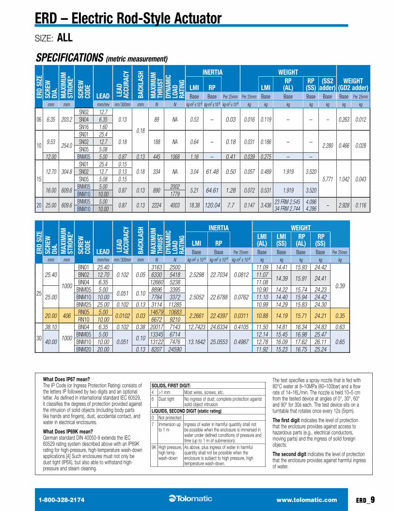
SPECIFICATIONS (metric measurement)
What Does IP67 mean?The IP Code (or Ingress Protection Rating) consists of the letters IP followed by two digits and an optional letter. As defined in international standard IEC 60529, it classifies the degrees of protection provided against the intrusion of solid objects (including body parts like hands and fingers), dust, accidental contact, and water in electrical enclosures.
What Does IP69K mean?German standard DIN 40050-9 extends the IEC 60529 rating system described above with an IP69K rating for high-pressure, high-temperature wash-down applications.[4] Such enclosures must not only be dust tight (IP6X), but also able to withstand high-pressure and steam cleaning.
SOLIDS, fIRST DIgIT:4 >1 mm Most wires, screws, etc.6 Dust tight No ingress of dust; complete protection against
solid object intrusionLIqUIDS, SEcOND DIgIT (static rating)0 Not protected7 Immersion up
to 1 mIngress of water in harmful quantity shall not be possible when the enclosure is immersed in water under defined conditions of pressure and time (up to 1 m of submersion).
9K High pressure, high temp. wash-down
As above, plus ingress of water in harmful quantity shall not be possible when the enclosure is subject to high pressure, high temperature wash-down.
The test specifies a spray nozzle that is fed with 80°C water at 8–10MPa (80–100bar) and a flow rate of 14–16L/min. The nozzle is held 10–5 cm from the tested device at angles of 0°, 30°, 60° and 90° for 30s each. The test device sits on a turntable that rotates once every 12s (5rpm).
The first digit indicates the level of protection that the enclosure provides against access to hazardous parts (e.g., electrical conductors, moving parts) and the ingress of solid foreign objects.
The second digit indicates the level of protection that the enclosure provides against harmful ingress of water.
SIZE: ALL
1-800-328-2174 www.tolomatic.comerd_10
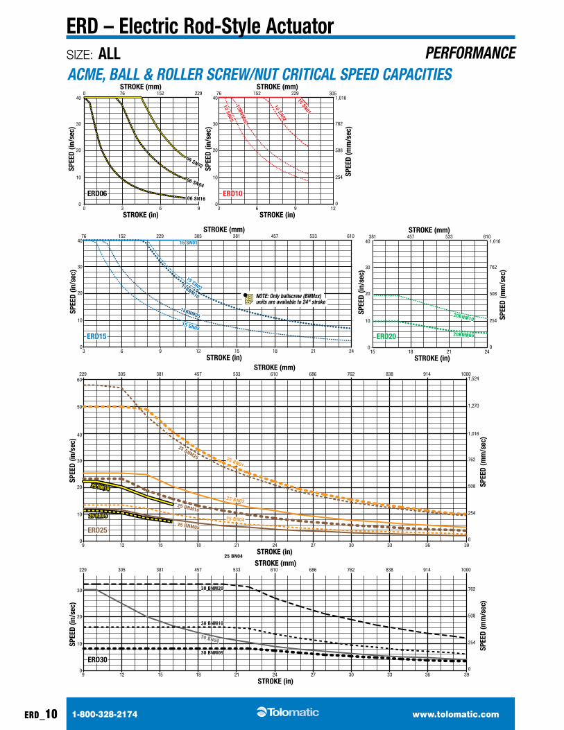
ERD – Electric Rod-Style ActuatorPERFORMANCE
ACME, BALL & ROLLER SCREW/NUT CRITICAL SPEED CAPACITIES
06 SN02
06 SN04
06 SN16
10 SN01
10 SN02
10 SN0510BNM
05
15 SN01
15 SN02
15 SN05
15BNM10
15BNM05 20BNM10
20BNM05
30 BNM20
30 BNM10
30 BNM05
30 BN04
25 RN05
25 RN10
25 BNM05
25 BNM10
25 BNM25
25 BN04
25 BN02
25 BN01
00
10
20
30
40152 229760
3 96
STROKE (in)
ERD06ERD06 ERD10ERD10
ERD15ERD15
ERD25ERD25
ERD20ERD20
STROKE (mm)
SPEE
D (in
/sec
)
06 SN02
06 SN04
06 SN160
10
20
30
40152 22976
3 96
STROKE (in)
STROKE (mm)
SPEE
D (in
/sec
)
10BNM05
10 SN01
10 SN02
10 SN05
0
10
20
30
40
254
508
762
1,016
0
152 229 305 381 457 533 61076
3 96
STROKE (in)
STROKE (mm)
381 457 533 610 686 762 838 914STROKE (mm)
SPEE
D (in
/sec
)
SPEE
D (m
m/s
ec)
12 15 2118 24
0
10
20
30
40
STROKE (in)
SPEE
D (in
/sec
)
15
305
12
229
9 2118 24 27 3330 36
1000
39
305
12
15BNM10
15BNM05
15 SN01
15 SN02
15 SN05
0
10
20
30
40
254
508
762
1,016
0
STROKE (in)
STROKE (mm)
SPEE
D (in
/sec
)
SPEE
D (m
m/s
ec)
254
508
762
1,016
50 1,270
60 1,524
0
SPEE
D (m
m/s
ec)
ERD30ERD30
381 457 533 610 686 762 838 914STROKE (mm)
0
10
20
30
STROKE (in)
SPEE
D (in
/sec
)
15
305
12
229
9 2118 24 27 3330 36
1000
39
254
508
762
0
SPEE
D (m
m/s
ec)
15 2118 24
381 533457 610
20BNM10
20BNM05
30 BNM20
30 BNM10
30 BNM05
25 BN04
25 BN04
25 BN02
25 BN01
25 BNM05
25 BNM10
25 BNM25
25 RN05
25 RN10
30 BN04
NOTE: Only ballscrew (BNMxx) units are available to 24" stroke
06 SN02
06 SN04+16
10 BN
10 SN
15 BN
20 BN
15 SN
30 BNM20
30 BNM10
30 BNM05
30 BN04
25 RN05
25 RN10
25 BNM25 25 BN01
25 BNM10
25 BNM05
25 BN04
25 BN02
0
200
300
400
500
100
0
890
1334
1779
2224
445
0
8900
13340
17790
22240
4450
5 10 15 20STROKE (in)
STROKE (mm)
THRU
ST (l
bf)
0
2000
3000
4000
5000
1000
THRU
ST (l
bf)
THRU
ST (N
)
THRU
ST (N
)
25
5 10 15 20
STROKE (in)25 30 35 40
127 254 381 508 635
STROKE (mm)127 254 381 508 635 762 889 1016
06 SN02
06 SN04+16
10 BN
10 SN
15 BN
20 BN
15 SN
30 BNM20
30 BNM10
30 BNM05
25 BN04
25 BN02
25 BNM25 25 BN01
25 BNM10
25 BNM05
25 RN05
25 RN10
30 BN04
SIZE: ALL
1-800-328-2174 www.tolomatic.com erd_11
ERD – Electric Rod-Style ActuatorSIZING
ACTUATOR
sizing software available at www.
tolomatic.com
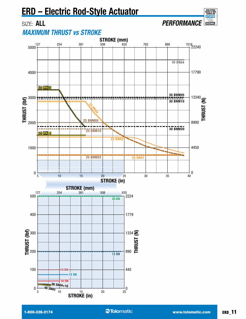
PERFORMANCEMAXIMUM THRUST vs STROKE
15BNM05
20BNM05
15BNM10
20BNM1010BNM
05
THRUST (N)2224 4448 6672 8896 11121 13345 15569 17793 20017
30 BNM20
30 BNM1030 BNM05 30 BN04
25 BN02
25 BN04
25 BNM1025 BNM05
25 BNM25
25 BN01
01
100
10,000
40,000
10
1,000
100,000
500 1000 1500
LIFE
(mill
ion
in)
LIFE
(mill
ion
mm
)
THRUST (lbf)
25
254
2,540
25,400
254,000
2,540,000THRUST (N)
2000
2224 4448 6672 8896
2500 3000 3500 4000
11121 13345 15569 17793
4500
20017
15BNM05
20BNM05
15BNM10
20BNM1010BNM
05
30 BNM20
30 BNM1030 BNM05 30 BN04
25 BN02
25 BN04
25 BNM1025 BNM05
25 BNM25
25 BN01
25 RN05
25 RN10
25 RN05
25 RN10
06 SN0206 SN04
06 SN16
15 SN01
15 SN02
15 SN05
10 SN0110 SN02
10 SN05
00
20
40
60
80
10 20 30SPEED (in/sec)
THRU
ST (l
bf)
0
89
178
267
356
THRU
ST (N
)
40
0 254 508 762SPEED (mm/sec)
1,016
06 SN0206 SN04
06 SN16
15 SN01
15 SN02
15 SN05
10 SN0110 SN02
10 SN05
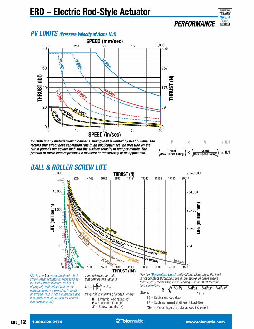
PV LIMITS: Any material which carries a sliding load is limited by heat buildup. The factors that affect heat generation rate in an application are the pressure on the nut in pounds per square inch and the surface velocity in feet per minute. The product of these factors provides a measure of the severity of an application.
P x v ≤ 0.1
( thrust x Speed ≤ 0.1((max. thrust Rating)) ((max. Speed Rating))
NOTE: The L10 expected life of a ball screw linear actuator is expressed as the linear travel distance that 90% of properly maintained ball screw manufactured are expected to meet or exceed. This is not a guarantee and this graph should be used for estima-tion purposes only.
The underlying formula that defines this value is:
l10 = ( c )3 • l ≡F
Travel life in millions of inches, where:c = dynamic load rating (lbf) F = Equivalent load (lbf) l = Screw lead (in/rev)
Use the "Equivalent Load" calculation below, when the load is not constant throughout the entire stroke. In cases where there is only minor variation in loading, use greatest load for life calculations.
Where:Pe = Equivalent load (lbs) Pn = each increment at different load (lbs) %n = Percentage of stroke at load increment
Pe =3√ %(P1)3+%(P2 )3+%(P3 )3+%(Pn )3
100
1-800-328-2174 www.tolomatic.comerd_12
ERD – Electric Rod-Style ActuatorSIZING
ACTUATOR
sizing software available at www.
tolomatic.com
PERFORMANCEPV LIMITS (Pressure Velocity of Acme Nut)
BALL & ROLLER SCREW LIFE
1-800-328-2174 www.tolomatic.com erd_13
ERD – Electric Rod-Style ActuatorSIZING
ACTUATOR
sizing software available at www.
tolomatic.com
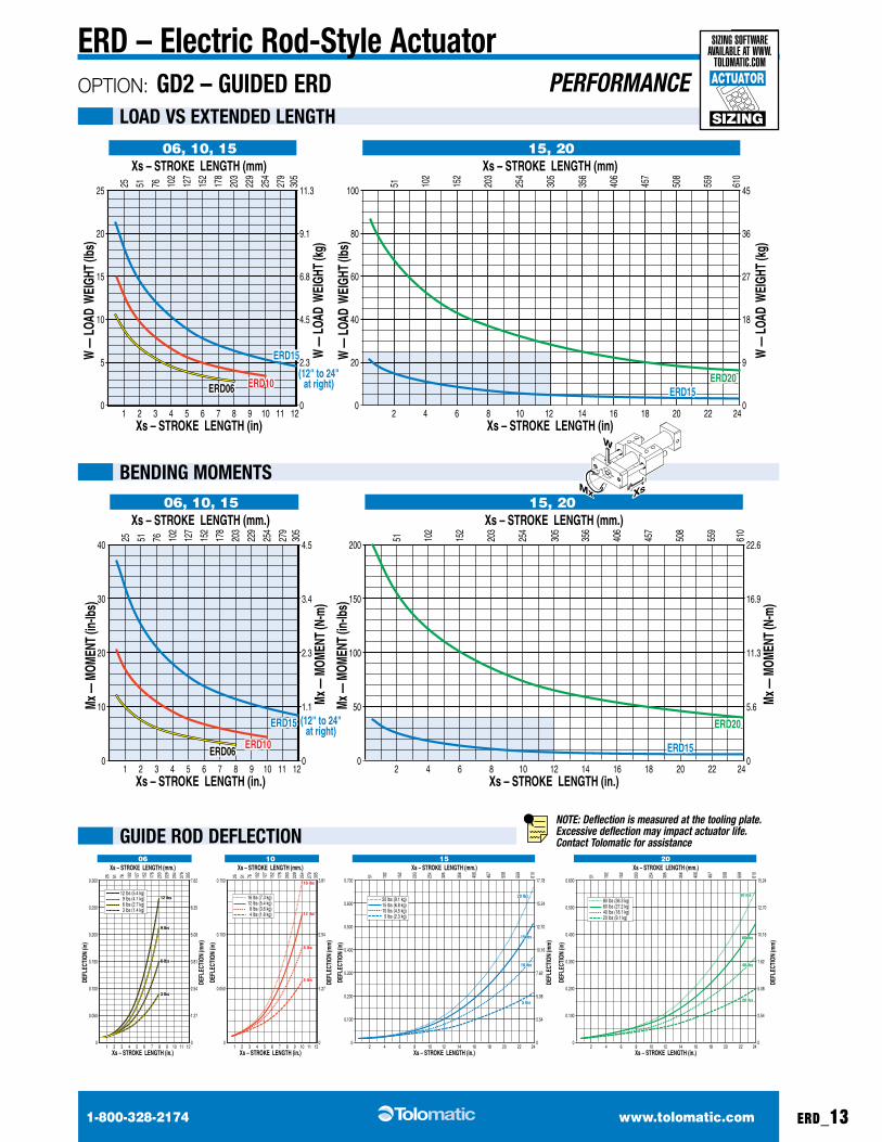
OPTION: GD2 – GuiDED ERD PERFORMANCE
BENDiNG momENtS
GuiDE RoD DEFlEctioN
loAD vS EXtENDED lENGtH
1 2 3 4 5 6 7 8 9 10 11 12
Xs – STROKE LENGTH (mm.)
Xs – STROKE LENGTH (in.)
76 102
127
152
178
203
229
254
279
305
25 51
40
30
20
0
10
4.5
3.4
0
1.1
2.3
Mx —
MOM
ENT
(in-lb
s)
Mx —
MOM
ENT
(N-m
)
2 4 6 8 10 12
Xs – STROKE LENGTH (mm.)
Xs – STROKE LENGTH (in.)
102
152
203
254
305
51 406
457
508
559
610
356
200
150
100
0
50Mx —
MOM
ENT
(in-lb
s)
14 16 18 20 22 24
22.6
16.9
0
5.6
11.3
Mx —
MOM
ENT
(N-m
)
06, 10, 15 15, 20
ERD06ERD06ERD10ERD10
ERD20ERD20
ERD15ERD15
ERD15ERD15 (12" to 24"at right)
1 2 3 4 5 6 7 8 9 10 11 12
Xs – STROKE LENGTH (mm.)
Xs – STROKE LENGTH (in.)
76 102
127
152
178
203
229
254
279
305
25 51
0.300
0.250
0.200
0.150
0.100
0.050
0
7.62
5.08
6.35
3.81
0
1.27
2.54
DEFL
ECTI
ON (i
n)
DEFL
ECTI
ON (m
m)
1 2 3 4 5 6 7 8 9 10 11 12
Xs – STROKE LENGTH (mm.)
Xs – STROKE LENGTH (in.)
76 102
127
152
178
203
229
254
279
305
25 51
0.150
0.100
0.050
0
3.81
0
1.27
2.54
DEFL
ECTI
ON (i
n)
DEFL
ECTI
ON (m
m)
06 10
2 4 6 8 10 12
Xs – STROKE LENGTH (mm.)
Xs – STROKE LENGTH (in.)
102
152
203
254
305
51
14 16 18 20 22 24
356
0.600
0.400
0.200
0.500
0.300
0.100
0
15.24
0
5.08
10.16
12.70
2.54
7.62
15.24
17.78
5.08
10.16
12.70
2.54
7.62
DEFL
ECTI
ON (i
n)
DEFL
ECTI
ON (m
m)
20
406
457
508
559
610
2 4 6 8 10 12
Xs – STROKE LENGTH (mm.)
Xs – STROKE LENGTH (in.)
102
152
203
254
305
51
14 16 18 20 22 24
356
0.700
0.500
0.300
0.600
0.400
0.200
0.100
0 0
DEFL
ECTI
ON (i
n)
DEFL
ECTI
ON (m
m)
15
406
457
508
559
610
12 lbs (5.4 kg) 9 lbs (4.1 kg) 6 lbs (2.7 kg) 3 lbs (1.4 kg)
16 lbs (7.3 kg)12 lbs (5.4 kg) 8 lbs (3.6 kg) 4 lbs (1.8 kg)
20 lbs (9.1 kg)15 lbs (6.8 kg)10 lbs (4.5 kg) 5 lbs (2.3 kg)
80 lbs (36.3 kg)60 lbs (27.2 kg)40 lbs (18.1 kg)20 lbs (9.1 kg)
12 lbs12 lbs
9 lbs9 lbs
6 lbs6 lbs
3 lbs3 lbs
16 lbs16 lbs
20 lbs20 lbs
15 lbs15 lbs
10 lbs10 lbs
5 lbs5 lbs
80 lbs80 lbs
60 lbs60 lbs
40 lbs40 lbs
20 lbs20 lbs
12 lbs12 lbs
8 lbs8 lbs
4 lbs4 lbs
SIZING
ACTUATOR
sizing software available at www.
tolomatic.com
1 2 3 4 5 6 7 8 9 10 11 12
Xs – STROKE LENGTH (mm)
Xs – STROKE LENGTH (in)
76 102
127
152
178
203
229
254
279
305
25 51
25
20
15
0
5
10
11.3
9.1
6.8
0
2.3
4.5
W —
LOA
D W
EIGH
T (lb
s)
W —
LOA
D W
EIGH
T (k
g)
2 4 6 8 10 12
Xs – STROKE LENGTH (mm)
Xs – STROKE LENGTH (in)10
2
152
203
254
305
51 406
457
508
559
610
356
100
80
60
0
20
40
W —
LOA
D W
EIGH
T (lb
s)
14 16 18 20 22 24
45
36
27
0
9
18
W —
LOA
D W
EIGH
T (k
g)
06, 10, 15 15, 20
ERD06ERD06 ERD10ERD10 ERD20ERD20
ERD15ERD15
ERD15ERD15
(12" to 24"at right)
NOTE: Deflection is measured at the tooling plate. Excessive deflection may impact actuator life. Contact Tolomatic for assistance
Xs
W
Mx
1-800-328-2174 www.tolomatic.com
DIMENSIONS 3D CAD available at www.tolomatic.com
erd_14
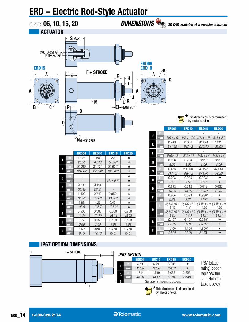
ERD – Electric Rod-Style ActuatorSIZE: 06, 10, 15, 20
ActuAtoR
A
A
A
A
B C
EF + STROKE
ERD15ERD06ERD10
(MOTOR SHAFTINTERFACE)
JAM NUT
G HI
II
JKLM
N(SHCS) CPLR
O
PQ
B
D
R
S MAX
T
FOOT MOUNT OPTION
P
U
V + STROKE
W
X
TRUNNION OPTION
FRONT FLANGE MOUNT OPTION
YAA Z
DDCC
BB
GG
EEFF
HH
II JAM NUT
ERD06 ERD10 ERD15 ERD20
Ain 1.125 1.580 2.220* *mm 28.58 40.13 56.39* *
Bin Ø1.287 Ø1.725 Ø2.625* *mm Ø32.69 Ø43.82 Ø66.68* *
cin - - - *mm - - M4 x 0.7* *
Din Ø.136 Ø.154 - *mm Ø3.45 Ø3.91 - *
Ein 1.400 0.740 0.850* *mm 35.56 18.80 21.59* *
Fin 3.88 4.20 5.40* *mm 98.5 106.7 137.2* *
Gin 0.500 0.500 0.600 0.750
mm 12.70 12.70 15.24 18.75
Hin 0.153 0.153 0.153 0.153
mm 3.89 3.89 3.89 3.89
Iin 0.375 0.500 0.750 0.750
mm 9.53 12.70 19.05 19.05
ERD06 ERD10 ERD15 ERD20
Jin - - - -
mm M6 x 1.0 M8 x 1.25 M12 x 1.75 M16 x 2.0
kin Ø.443 Ø.686 Ø1.041 1.323
mm Ø11.25 Ø17.42 Ø26.40 33.60
lin - - - -
mm M16 x 1.5 M24 x 1.5 M34 x 1.5 M44 x 1.5
IIin 0.236 0.236 0.315 0.315
mm 6.00 6.00 8.00 8.00
min Ø.686 Ø1.040 Ø1.638 Ø2.051
mm Ø17.42 Ø26.42 Ø41.61 52.20
Nin 0.098 0.098 0.098* *mm 2.50 2.50 2.50* *
oin 0.512 0.512 0.512 0.920
mm 13.00 13.00 13.00 23.37
Pin 0.264 0.323 0.298* *mm 6.71 8.20 7.57* *
Qin (2) M4 x 0.7
↓ .10(2) M6 x 1.0
↓ .31(2) M6 x 1.0
↓ .50(2) M6 x 1.0
↓ .50
mm (2) M4 x 0.7 ↓ 2.5
(2) M6 x 1.0 ↓ 7.9
(2) M6 x 1.0 ↓ 12.7
(2) M6 x 1.0 ↓ 12.7
Rin Ø.197 Ø.197 Ø.250* *mm Ø5.00 Ø5.00 Ø6.35* *
Sin 1.100 1.100 1.250* *mm 27.94 27.94 31.75* *
IP67 OPTIONERD06 ERD10 ERD15 ERD20
Fin 4.59 4.79 6.00* *mm 116.6 121.8 152.1* *
Gin 1.744 1.739 2.088 2.853
mm 44.30 44.17 53.04 72.48I Surface for mounting options
06
10
F + STROKEG
I
iP67 oPtioN DimENSioNS
IP67 (static rating) option replaces the Jam nut (II in table above)
*This dimension is determined by motor choice.
*This dimension is determined by motor choice.
1-800-328-2174 www.tolomatic.com
DIMENSIONS 3D CAD available at www.tolomatic.com
erd_15
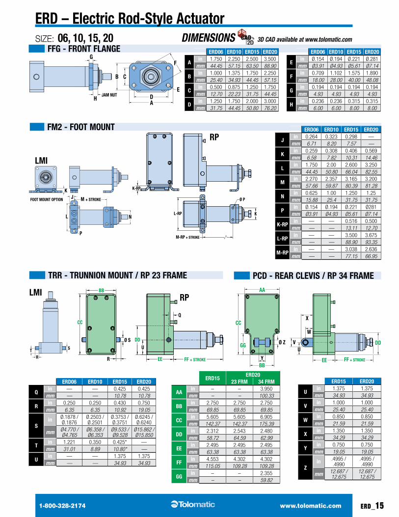
ERD – Electric Rod-Style ActuatorSIZE: 06, 10, 15, 20
Fm2 - Foot mouNt
tRR - tRuNNioN mouNt / RP 23 FRAmE
FFG - FRoNt FlANGE
PcD - REAR clEviS / RP 34 FRAmE
K
FOOT MOUNT OPTION J
L
M + STROKE
N
P
K-RP
L-RP K
Ø P
M-RP + STROKE
FRONT FLANGE MOUNT OPTION
CB
A
F
DE
G
HJAM NUT
A
A
A
A
B C
EF + STROKE
ERD15ERD06ERD10
(MOTOR SHAFTINTERFACE)
JAM NUT
G HI
II
JKLM
N(SHCS) CPLR
O
PQ
B
D
R
S MAX ERD06 ERD10 ERD15 ERD20
Ain 1.750 2.250 2.500 3.500
mm 44.45 57.15 63.50 88.90
Bin 1.000 1.375 1.750 2.250
mm 25.40 34.93 44.45 57.15
cin 0.500 0.875 1.250 1.750
mm 12.70 22.23 31.75 44.45
Din 1.250 1.750 2.000 3.000
mm 31.75 44.45 50.80 76.20
ERD15ERD20
23 FRm 34 FRm
AAin – – 3.950
mm – – 100.33
BBin 2.750 2.750 2.750
mm 69.85 69.85 69.85
ccin 5.605 5.605 6.905
mm 142.37 142.37 175.39
DDin 2.312 2.543 2.480
mm 58.72 64.59 62.99
EEin 2.495 2.495 2.495
mm 63.38 63.38 63.38
FFin 4.553 4.302 4.302
mm 115.05 109.28 109.28
GGin – – 2.355
mm – – 59.82
ERD06 ERD10 ERD15 ERD20
Qin — — 0.425 0.425
mm — — 10.78 10.78
Rin 0.250 0.250 0.430 0.750
mm 6.35 6.35 10.92 19.05
Sin Ø.1878 /
Ø.1876Ø.2503 / Ø.2501
Ø.3753 / Ø.3751
Ø.6245 / Ø.6240
mm Ø4.770 / Ø4.765
Ø6.358 / Ø6.353
Ø9.533 / Ø9.528
Ø15.862 / Ø15.850
tin 1.221 0.350 0.425* —
mm 31.01 8.89 10.80* —
uin — — 1.375 1.375
mm — — 34.93 34.93
ERD06 ERD10 ERD15 ERD20
Jin 0.264 0.323 0.298 —
mm 6.71 8.20 7.57 —
kin 0.259 0.308 0.406 0.569
mm 6.58 7.82 10.31 14.46
lin 1.750 2.00 2.600 3.250
mm 44.45 50.80 66.04 82.55
min 2.270 2.357 3.165 3.200
mm 57.66 59.87 80.39 81.28
Nin 0.625 1.00 1.250 1.25
mm 15.88 25.4 31.75 31.75
Pin Ø.154 Ø.194 Ø.221 Ø281
mm Ø3.91 Ø4.93 Ø5.61 Ø7.14
k-RPin — — 0.516 0.500
mm — — 13.11 12.70
l-RPin — — 3.500 3.675
mm — — 88.90 93.35
m-RPin — — 3.038 2.636
mm — — 77.15 66.95
ERD15 ERD20
uin 1.375 1.375
mm 34.93 34.93
vin 1.000 1.000
mm 25.40 25.40
Win 0.850 0.850
mm 21.59 21.59
Xin 1.350 1.350
mm 34.29 34.29
yin 0.750 0.750
mm 19.05 19.05
Zin .4995 /
.4990.4995 / .4990
mm 12.687 / 12.675
12.687 / 12.675
CC
BB
Ø S
R
UDD
EE
Q
FF + STROKE
lmi
lmi
RP
RPAA
BB
GG
CC
Y
X
DD
W
VU
FF + STROKEEE
Ø Z
TRUNNION OPTIONR
T S
ERD06 ERD10 ERD15 ERD20
Ein Ø.154 Ø.194 Ø.221 Ø.281
mm Ø3.91 Ø4.93 Ø5.61 Ø7.14
Fin 0.709 1.102 1.575 1.890
mm 18.00 28.00 40.00 48.08
Gin 0.194 0.194 0.194 0.194
mm 4.93 4.93 4.93 4.93
Hin 0.236 0.236 0.315 0.315
mm 6.00 6.00 8.00 8.00
1-800-328-2174 www.tolomatic.com
DIMENSIONS 3D CAD available at www.tolomatic.com
erd_16
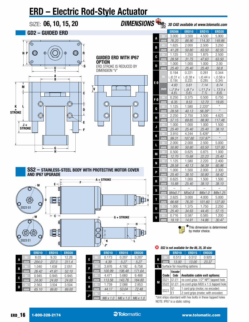
ERD – Electric Rod-Style ActuatorSIZE: 06, 10, 15, 20
ERD10 ERD15 ERD20
Ain 8.03 9.33 12.26
mm 204.0 237.0 311.4
Bin 1.040 1.638 2.051
mm 26.42 41.61 52.10
cin 0.945 0.945 0.945
mm 24.00 24.00 24.00
Din 2.563 3.504 3.504
mm 65.10 89.00 89.00
GD2 – GuiDED ERD
SS2 – StAiNlESS-StEEl BoDy WitH PRotEctivE motoR covER AND iP67 uPGRADE
A + STROKE
G + STROKE
B
C
D
E F
J*
H
K L
M
SS23 G1
SS23 E1
M
ERD10 ERD15 ERD20
Ein 0.173 0.207 0.207
mm 4.39 5.27 5.27
Fin 3.976 4.192 6.758
mm 100.99 106.48 171.64
Gin 4.471 5.660 6.488
mm 113.56 143.76 164.80
Hin 1.739 2.088 2.853
mm 44.17 53.04 72.48
J*in – – –
mm M6 x 1.0 M6 x 1.0 M6 x 1.0
ERD10 ERD15 ERD20
kin 0.512 0.512 0.920
mm 13.00 13.00 23.37l Surface for mounting options
N P
UT
S
R
M
L
AB
J + STROKE
CV
D
F
GH
K+
STROKE
E
ERD06 ERD10 ERD15 ERD20
Ain 3.000 3.500 4.500 5.900
mm 76.20 88.90 114.30 149.86
Bin 1.625 2.000 2.500 3.250
mm 41.28 50.80 63.50 82.55
cin 1.125 1.250 1.875 2.500
mm 28.58 31.75 47.63 63.50
Din 1.000 1.000 1.000 2.00
mm 25.40 25.40 25.40 50.8
E Ø
in0.194 0.221 0.281 0.3440.31 x 0.19
0.38 x 0.22
0.44 x 0.28
0.56 x 0.34
mm4.93 5.61 7.14 8.747.9 x
4.8 9.7 x
5.6 11.2 x 7.1
13.5 x 8.6
F Øin 0.250 0.375 0.500 0.750
mm 6.35 9.53 12.70 19.05
Gin 1.125 1.580 2.220* *
mm 28.58 40.13 56.39* *
Hin 2.250 2.750 3.500 4.625
mm 57.15 69.85 88.90 117.48
Jin 1.000 1.000 1.000 1.500
mm 25.40 25.40 25.40 38.10
kin 3.910 4.244 5.428* *
mm 99.31 107.80 137.87* *
lin 2.000 2.000 2.500 5.000
mm 50.80 50.80 63.50 127.00
min 0.500 0.625 0.875 1.000
mm 12.70 15.88 22.23 25.40
Nin 1.125 1.580 2.220 2.400
mm 28.58 40.13 56.39 60.96
Pin 1.000 1.500 2.000 2.300
mm 25.40 38.10 50.80 58.42
Rin 0.625 1.000 1.500 1.500
mm 15.88 25.40 38.10 38.10
Sin – – – –
mm M4x0.7 M5x0.8 M6x1.0 M8x1.25
tin 2.625 3.000 4.000 5.000
mm 66.68 76.20 101.60 127.00
uin 1.000 1.375 1.750 2.250
mm 25.40 34.93 44.45 57.15
vin 0.716 0.587 0.585 1.200
mm 18.19 14.91 14.86 30.47
GuiDED ERD WitH iP67 oPtioNERD STROkE iS REDuCED By DiMENSiON “V”
m
codeEncoder
code Available cable exit options:SS21 G1,E1 no cord grips 1/2" NPT tapped holeSS22 G1,E1 no cord grips M20 x 1.5 tapped hole
SS23G1 1 cord grip (motor, no encoder)e1 2 cord grips (motor, with encoder)
*unit ships standard with hex bolts in these tapped holesNOTE: iP67 is a static rating
SS2 is not available for the 06, 25, 30 size
*This dimension is determined by motor choice.
1-800-328-2174 www.tolomatic.com
DIMENSIONS 3D CAD available at www.tolomatic.com
erd_17
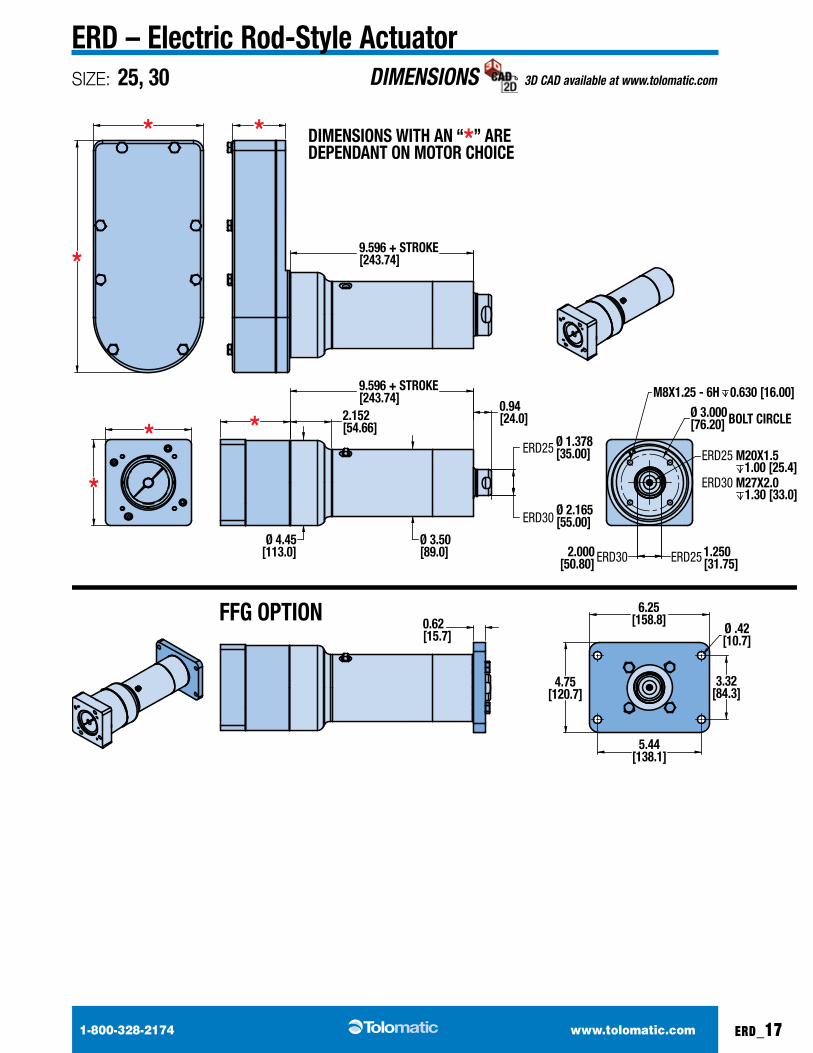
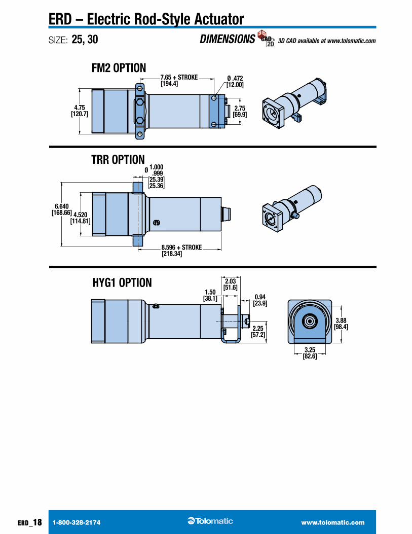
ERD – Electric Rod-Style ActuatorSIZE: 25, 30
FM2 OPTION
TRR OPTION
DIMENSIONS WITH AN “*” AREDEPENDANT ON MOTOR CHOICE
FFG OPTION
HYG1 OPTION
9.596 + STROKE[243.74]
9.596 + STROKE[243.74]
Ø 3.50[89.0]
Ø 2.165[55.00]
Ø 1.378[35.00]
Ø 4.45[113.0]
ERD25
2.152[54.66]*
* *
*
*
*ERD30
0.94[24.0] Ø 3.000
[76.20] BOLT CIRCLE
M8X1.25 - 6H 0.630 [16.00]
ERD25 M20X1.51.00 [25.4]
ERD30 M27X2.01.30 [33.0]
ERD25 1.250[31.75]ERD302.000
[50.80]
0.62[15.7]
4.75[120.7]
5.44[138.1]
6.25[158.8]
3.32[84.3]
Ø .42[10.7]
7.65 + STROKE[194.4]
8.596 + STROKE[218.34]
4.75[120.7]
2.75[69.9]
Ø .472[12.00]
6.640[168.66]
Ø 1.000 .999
[25.39] 25.36
4.520[114.81]
1.50[38.1]
2.03[51.6]
0.94[23.9]
2.25[57.2]
3.88[98.4]
3.25[82.6]
1-800-328-2174 www.tolomatic.com
DIMENSIONS 3D CAD available at www.tolomatic.com
erd_18
ERD – Electric Rod-Style ActuatorSIZE: 25, 30
FM2 OPTION
TRR OPTION
DIMENSIONS WITH AN “*” AREDEPENDANT ON MOTOR CHOICE
FFG OPTION
HYG1 OPTION
9.596 + STROKE[243.74]
9.596 + STROKE[243.74]
Ø 3.50[89.0]
Ø 2.165[55.00]
Ø 1.378[35.00]
Ø 4.45[113.0]
ERD25
2.152[54.66]*
* *
*
*
*ERD30
0.94[24.0] Ø 3.000
[76.20] BOLT CIRCLE
M8X1.25 - 6H 0.630 [16.00]
ERD25 M20X1.51.00 [25.4]
ERD30 M27X2.01.30 [33.0]
ERD25 1.250[31.75]ERD302.000
[50.80]
0.62[15.7]
4.75[120.7]
5.44[138.1]
6.25[158.8]
3.32[84.3]
Ø .42[10.7]
7.65 + STROKE[194.4]
8.596 + STROKE[218.34]
4.75[120.7]
2.75[69.9]
Ø .472[12.00]
6.640[168.66]
Ø 1.000 .999
[25.39] 25.36
4.520[114.81]
1.50[38.1]
2.03[51.6]
0.94[23.9]
2.25[57.2]
3.88[98.4]
3.25[82.6]
1-800-328-2174 www.tolomatic.com erd_19
ERD – Electric Rod-Style ActuatorALTERNATIVE MOTOR DIMENSIONS 3D CAD available at www.tolomatic.com
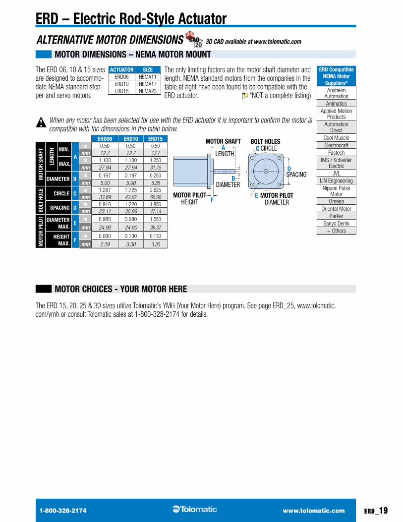
motoR DimENSioNS – NEmA motoR mouNt
the eRd 06, 10 & 15 sizes are designed to accommo-date NEMA standard step-per and servo motors.
The ERD 15, 20, 25 & 30 sizes utilize Tolomatic's yMH (your Motor Here) program. See page ERD_25, www.tolomatic.com/ymh or consult Tolomatic sales at 1-800-328-2174 for details.
the only limiting factors are the motor shaft diameter and length. NEMA standard motors from the companies in the table at right have been found to be compatible with the eRd actuator. ( *NOT a complete listing)
When any motor has been selected for use with the ERD actuator it is important to confirm the motor is compatible with the dimensions in the table below.
ActuAtoR SiZEeRd06 NEMA11eRd10 NEMA17eRd15 NEMA23
ERD compatibleNEmA motor Suppliers*anaheim
automationanimatics
Applied Motion Products
automation direct
Cool Muscleelectrocraft
FastechiMS / Scheider
electricJVL
LiN Engineeringnippon Pulse
MotorOmega
Oriental MotorParker
Sanyo Denki+ Others
ERD06 ERD10 ERD15
mot
oR S
HAFt
lENG
tH miN.A
in 0.50 0.50 0.50mm 12.7 12.7 12.7
mAX.in 1.100 1.100 1.250
mm 27.94 27.94 31.75
DiAmEtER Bin 0.197 0.197 0.250
mm 5.00 5.00 6.35
Bolt
Hol
E
ciRclE cin 1.287 1.725 2.625
mm 33.69 43.82 66.68
SPAciNG Din 0.910 1.220 1.856
mm 23.11 30.99 47.14
mot
oR P
ilot DiAmEtER
mAX.E
in 0.980 0.980 1.550
mm 24.90 24.90 39.37
HEiGHtmAX.
Fin 0.090 0.130 0.130
mm 2.29 3.30 3.30
DB
A CMOTOR SHAFT BOLT HOLES
DIAMETER
E MOTOR PILOTDIAMETERF
MOTOR PILOTHEIGHT
LENGTHCIRCLE
SPACING
motoR cHoicES - youR motoR HERE
SIZE: ALL
1-800-328-2174 www.tolomatic.comerd_20
ERD – Electric Rod-Style ActuatorSWITCHES
SWitcH iNStAllAtioN - Field replAcemenT insTrucTions
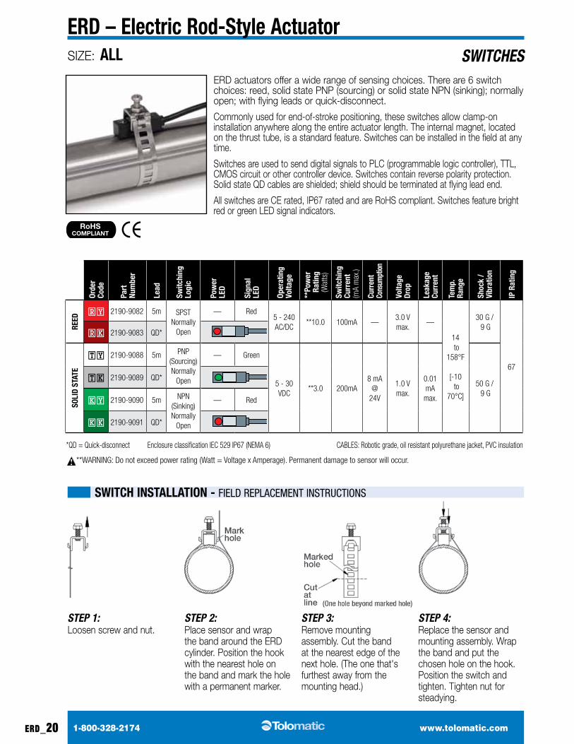
*QD = Quick-disconnect Enclosure classification iEC 529 iP67 (NEMA 6) CABLES: Robotic grade, oil resistant polyurethane jacket, PVC insulation
**WARNiNG: Do not exceed power rating (Watt = Voltage x Amperage). Permanent damage to sensor will occur.
orde
r co
de
Part
Nu
mbe
r
lead
Switc
hing
lo
gic
Pow
er
lED
Sign
al
lED
oper
atin
g vo
ltage
**Po
wer
Ratin
g
(W
atts
)
Switc
hing
cu
rren
t (m
a m
ax.)
curr
ent
cons
umpt
ion
volta
ge
Drop
leak
age
curr
ent
tem
p.
Rang
e
Shoc
k /
vibr
atio
n
iP R
atin
g
REED
RY 2190-9082 5m SPST normally
Open
— Red5 - 240 AC/DC
**10.0 100ma —3.0 V max.
—
14 to
158°F
[-10 to
70°C]
30 G / 9 G
67
Rk 2190-9083 Qd*
Soli
D St
AtE
TY 2190-9088 5m PnP (Sourcing) normally
Open
— Green
5 - 30 VDC
**3.0 200ma8 ma
@ 24V
1.0 V max.
0.01 ma
max.
50 G / 9 G
Tk 2190-9089 Qd*
kY 2190-9090 5m nPn (Sinking) normally
Open
— Red
kk 2190-9091 Qd*
ERD actuators offer a wide range of sensing choices. There are 6 switch choices: reed, solid state PNP (sourcing) or solid state NPN (sinking); normally open; with flying leads or quick-disconnect.
Commonly used for end-of-stroke positioning, these switches allow clamp-on installation anywhere along the entire actuator length. The internal magnet, located on the thrust tube, is a standard feature. Switches can be installed in the field at any time.
Switches are used to send digital signals to PLC (programmable logic controller), TTL, CMOS circuit or other controller device. Switches contain reverse polarity protection. Solid state QD cables are shielded; shield should be terminated at flying lead end.
All switches are CE rated, IP67 rated and are RoHS compliant. Switches feature bright red or green LED signal indicators.
RoHSCOMPLIANT
STEP 1:Loosen screw and nut.
STEP 2:Place sensor and wrap the band around the ERD cylinder. Position the hook with the nearest hole on the band and mark the hole with a permanent marker.
STEP 3:Remove mounting assembly. Cut the band at the nearest edge of the next hole. (The one that's furthest away from the mounting head.)
STEP 4:Replace the sensor and mounting assembly. Wrap the band and put the chosen hole on the hook. Position the switch and tighten. Tighten nut for steadying.
SIZE: ALL
1-800-328-2174 www.tolomatic.com erd_21
ERD – Electric Rod-Style ActuatorSWITCHES
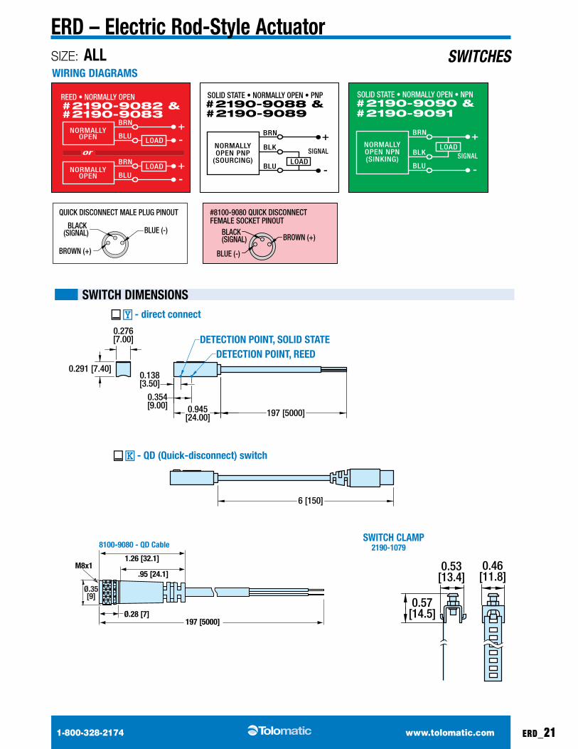
SWitcH DimENSioNS
0.46[11.8]
0.57[14.5]
0.53[13.4]
SWitcH clAmP 2190-1079
WiRiNG DiAGRAmS
NORMALLYOPEN PNP
(SOURCING)
BRN
BLK+
SIGNALLOAD
BLU -
NORMALLYOPEN NPN(SINKING)
BRN
BLK
+
SIGNALLOAD
BLU -NORMALLYOPEN
BRN
BLU+-
LOAD
NORMALLYOPEN
BRN
BLU+-LOAD
or
#2190-9091
SOLID STATE • NORMALLY OPEN • NPN#2190-9090 &
#2190-9089
SOLID STATE • NORMALLY OPEN • PNP#2190-9088 &
#2190-9083
REED • NORMALLY OPEN#2190-9082 &
LOAD
LOAD
LOAD
NORMALLYCLOSED
BRN
BLU+-
LOAD
NORMALLYCLOSED
BRN
BLU+-LOAD
or
NORMALLYOPEN PNP
(SOURCING)
BRN
BLK+
SIGNALLOAD
BLU -
NORMALLYOPEN NPN(SINKING)
BRN
BLK
+
SIGNALLOAD
BLU -
NORMALLYCLOSED PNP(SOURCING)
BRN
BLK+
SIGNALLOAD
BLU -
NORMALLYCLOSED NPN
(SINKING)
BRN
BLK
+
SIGNALLOAD
BLU -
NORMALLYOPEN
BRN
BLU+-
LOAD
NORMALLYOPEN
BRN
BLU+-LOAD
or
TY, #8100-9088, • TK, #8100-9089SOLID STATE • NORMALLY OPEN • PNP
NY, #8100-9084, • NK, #8100-9085REED • NORMALLY CLOSED
QUICK DISCONNECT MALE PLUG PINOUT #8100-9080 QUICK DISCONNECT FEMALE SOCKET PINOUT
RY, #8100-9082, • RK, #8100-9083REED • NORMALLY OPEN
KY, #8100-9090, • KK, #8100-9091SOLID STATE • NORMALLY OPEN • NPN
PY, #8100-9092, • PK, #8100-9093SOLID STATE • NORMALLY CLOSED • PNP
HY, #8100-9094, • HK, #8100-9095SOLID STATE • NORMALLY CLOSED • NPN
BROWN (+)
BLUE (-)BLACK (SIGNAL)
BLUE (-)
BROWN (+)BLACK(SIGNAL)
MOUNTING DIMENSIONSSWITCH DIMENSIONS
1.50 [38.2]
0.63 [16.0]0.33 [8.4]
Ø.28 [7]
.95 [24.1]
1.26 [32.1]
0.83 [21.1]
DETECTION POINT REEDDETECTION POINT
SOLID STATE
13.68 [347]
This screw secures switch to bracket
This screw secures bracket to actuator
M8x1
M8x1
197.33 [5012]
197 [5000]
_ K - QD (Quick-disconnect) switch
8100-9080 - QD Cable
_ Y - direct connect
0.29 [7.4]
BA 1.50
[38.2]
Ø.35[9]
CAUTION: DO NOT OVERTIGHTEN SWITCH HARDWARE WHEN INSTALLING
0.291 [7.40]
0.276[7.00]
0.138[3.50]
0.354[9.00]
197 [5000]0.945[24.00]
DETECTION POINT, REEDDETECTION POINT, SOLID STATE
6 [150]
_ K - QD (Quick-disconnect) switch
_ Y - direct connect
SIZE: ALL
1-800-328-2174 www.tolomatic.com
SPECIFICATIONS
erd_22
ERD – Electric Rod-Style ActuatorSIZING
ACTUATOR
sizing software available at www.
tolomatic.com
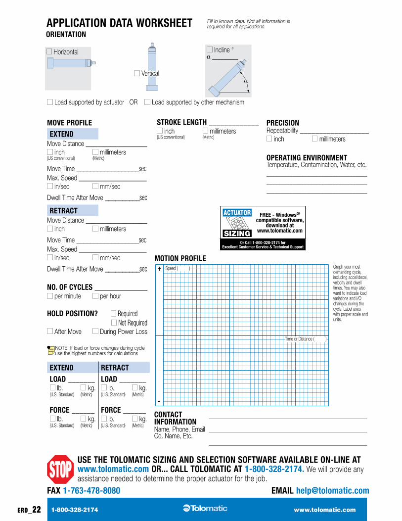
StRokE lENGtH _____________ inch millimeters
(US conventional) (Metric)
APPlicAtioN DAtA WoRkSHEEt
uSE tHE tolomAtic SiZiNG AND SElEctioN SoFtWARE AvAilABlE oN-liNE At www.tolomatic.com oR... cAll tolomAtic At 1-800-328-2174. We will provide any assistance needed to determine the proper actuator for the job.
PREciSioN Repeatability __________________
inch millimeters
oPERAtiNG ENviRoNmENt Temperature, Contamination, Water, etc._________________________________________________________________________________________________________
coNtAct iNFoRmAtioN Name, Phone, Email Co. Name, Etc.
Load supported by actuator OR Load supported by other mechanism
Horizontal
Vertical
oRiENtAtioN
Incline ° a _________
movE PRoFilE EXtEND
Move Distance ________________ inch millimeters
(US conventional) (Metric)
Move Time __________________secMax. Speed __________________
in/sec mm/sec
Dwell Time After Move __________sec
REtRActMove Distance ________________
inch millimeters
Move Time __________________secMax. Speed __________________
in/sec mm/sec
Dwell Time After Move __________sec
No. oF cyclES ______________ per minute per hour
HolD PoSitioN? Required Not Required
After Move During Power Loss
NOTE: If load or force changes during cycle use the highest numbers for calculations
EXtEND REtRActloAD _______
lb. kg. (U.S. Standard) (Metric)
FoRcE ______ lb. kg.
(U.S. Standard) (Metric)
loAD _______ lb. kg.
(U.S. Standard) (Metric)
FoRcE ______ lb. kg.
(U.S. Standard) (Metric)
FAX 1-763-478-8080 EmAil [email protected]
Graph your most demanding cycle, including accel/decel, velocity and dwell times. You may also want to indicate load variations and I/O changes during the cycle. Label axes with proper scale and units.
motioN PRoFilE+ Speed ( )
Time or Distance ( )
Fill in known data. Not all information is required for all applications
-
SIZING
ACTUATOR FREE - Windows® compatible software,
download at www.tolomatic.com
or call 1-800-328-2174 for Excellent customer Service & technical Support
1-800-328-2174 www.tolomatic.com erd_23
ERD – Electric Rod-Style ActuatorSIZING
ACTUATOR
sizing software available at www.
tolomatic.com
Selection GuidelinesSIZING
ACTUATOR
sizing software available at www.
tolomatic.com
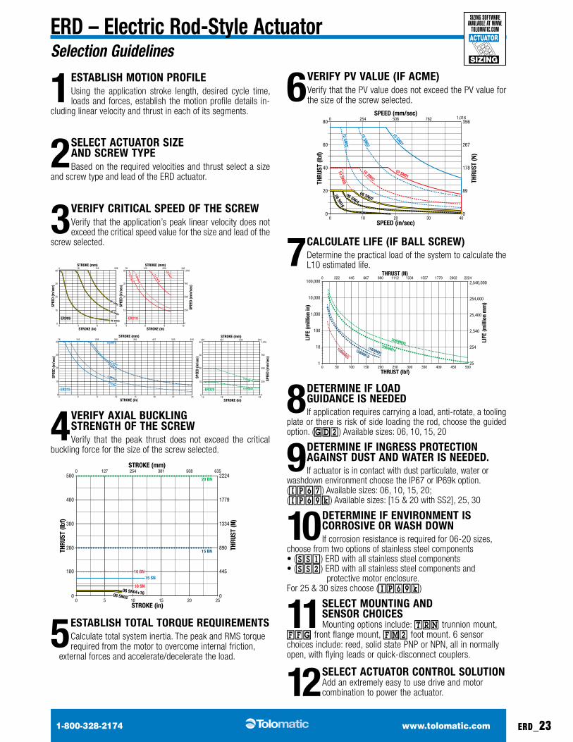
1 EStABliSH motioN PRoFilE using the application stroke length, desired cycle time, loads and forces, establish the motion profile details in-
cluding linear velocity and thrust in each of its segments.
2 SElEct ActuAtoR SiZE AND ScREW tyPE Based on the required velocities and thrust select a size
and screw type and lead of the eRd actuator.
3 vERiFy cRiticAl SPEED oF tHE ScREW Verify that the application’s peak linear velocity does not exceed the critical speed value for the size and lead of the
screw selected.
06 SN02
06 SN04
06 SN16
10 SN01
10 SN02
10 SN0510BNM
05
15 SN01
15 SN02
15 SN05
15BNM10
15BNM05 20BNM10
20BNM05
30 BNM20
30 BNM10
30 BNM05
30 BN04
25 RN05
25 RN10
25 BNM05
25 BNM10
25 BNM25
25 BN04
25 BN02
25 BN01
00
10
20
30
40152 229760
3 96
STROKE (in)
ERD06ERD06 ERD10ERD10
ERD15ERD15
ERD25ERD25
ERD20ERD20
STROKE (mm)
SPEE
D (in
/sec
)
06 SN02
06 SN04
06 SN160
10
20
30
40152 22976
3 96
STROKE (in)
STROKE (mm)
SPEE
D (in
/sec
)
10BNM05
10 SN01
10 SN02
10 SN05
0
10
20
30
40
254
508
762
1,016
0
152 229 305 381 457 533 61076
3 96
STROKE (in)
STROKE (mm)
381 457 533 610 686 762 838 914STROKE (mm)
SPEE
D (in
/sec
)
SPEE
D (m
m/s
ec)
12 15 2118 24
0
10
20
30
40
STROKE (in)
SPEE
D (in
/sec
)
15
305
12
229
9 2118 24 27 3330 36
1000
39
305
12
15BNM10
15BNM05
15 SN01
15 SN02
15 SN05
0
10
20
30
40
254
508
762
1,016
0
STROKE (in)
STROKE (mm)
SPEE
D (in
/sec
)
SPEE
D (m
m/s
ec)
254
508
762
1,016
50 1,270
60 1,524
0
SPEE
D (m
m/s
ec)
ERD30ERD30
381 457 533 610 686 762 838 914STROKE (mm)
0
10
20
30
STROKE (in)
SPEE
D (in
/sec
)
15
305
12
229
9 2118 24 27 3330 36
1000
39
254
508
762
0
SPEE
D (m
m/s
ec)
15 2118 24
381 533457 610
20BNM10
20BNM05
30 BNM20
30 BNM10
30 BNM05
25 BN04
25 BN04
25 BN02
25 BN01
25 BNM05
25 BNM10
25 BNM25
25 RN05
25 RN10
30 BN04
4 vERiFy AXiAl BuckliNG StRENGtH oF tHE ScREWVerify that the peak thrust does not exceed the critical
buckling force for the size of the screw selected.
06 SN02
06 SN04+16
10 BN
10 SN
15 BN
20 BN
15 SN
00
200
300
400
500
100
0
890
1334
1779
2224
445
5 10 15 20STROKE (in)
STROKE (mm)
THRU
ST (l
bf)
THRU
ST (N
)
25
0 127 254 381 508 635
06 SN02
06 SN04+16
10 BN
10 SN
15 BN
20 BN
15 SN
5EStABliSH totAl toRQuE REQuiREmENtS Calculate total system inertia. The peak and RMS torque required from the motor to overcome internal friction,
external forces and accelerate/decelerate the load.
6 vERiFy Pv vAluE (iF AcmE)Verify that the PV value does not exceed the PV value for the size of the screw selected.
06 SN0206 SN04
06 SN16
15 SN01
15 SN02
15 SN05
10 SN0110 SN02
10 SN05
00
20
40
60
80
10 20 30SPEED (in/sec)
THRU
ST (l
bf)
0
89
178
267
356
THRU
ST (N
)
40
0 254 508 762SPEED (mm/sec)
1,016
06 SN0206 SN04
06 SN16
15 SN01
15 SN02
15 SN05
10 SN0110 SN02
10 SN05
7 cAlculAtE liFE (iF BAll ScREW)determine the practical load of the system to calculate the L10 estimated life.
15BNM10
20BNM1015BNM05
20BNM0510BNM05
01
100
10,000
10
1,000
100,000
50 100 150
LIFE
(mill
ion
in)
LIFE
(mill
ion
mm
)
THRUST (lbf)
25
254
2,540
25,400
254,000
2,540,000
THRUST (N)
200
0 222 445 667 890
250 300 350 400
1112 1334 1557 1779
450 500
2002 2224
15BNM10
20BNM1015BNM05
20BNM0510BNM05
8 DEtERmiNE iF loAD GuiDANcE iS NEEDEDif application requires carrying a load, anti-rotate, a tooling
plate or there is risk of side loading the rod, choose the guided option. (GD2 ) Available sizes: 06, 10, 15, 20
9DEtERmiNE iF iNGRESS PRotEctioN AGAiNSt DuSt AND WAtER iS NEEDED. If actuator is in contact with dust particulate, water or
washdown environment choose the IP67 or IP69k option. (IP67 ) Available sizes: 06, 10, 15, 20; (IP69k ) Available sizes: [15 & 20 with SS2], 25, 30
10DEtERmiNE iF ENviRoNmENt iS coRRoSivE oR WASH DoWNif corrosion resistance is required for 06-20 sizes,
choose from two options of stainless steel components • (SS1 ) eRd with all stainless steel components • (SS2 ) eRd with all stainless steel components and protective motor enclosure. For 25 & 30 sizes choose (IP69k )
11SElEct mouNtiNG AND SENSoR cHoicES Mounting options include: TRN trunnion mount,
FFG front flange mount, FM2 foot mount. 6 sensor choices include: reed, solid state PNP or NPN, all in normally open, with flying leads or quick-disconnect couplers.
12SElEct ActuAtoR coNtRol SolutioN add an extremely easy to use drive and motor combination to power the actuator.
1-800-328-2174 www.tolomatic.comerd_24
ERD – Electric Rod-Style ActuatorSIZING
ACTUATOR
sizing software available at www.
tolomatic.com
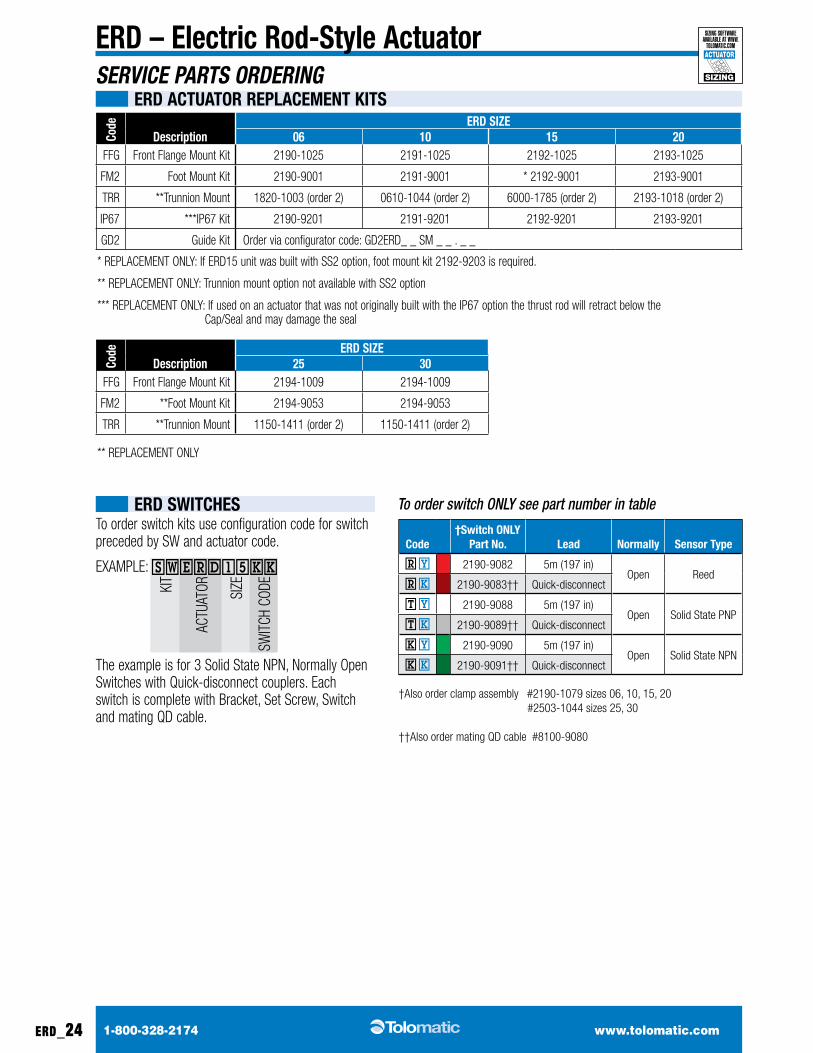
ERD SWitcHES
code ERD SiZE
Description 06 10 15 20FFG Front Flange Mount kit 2190-1025 2191-1025 2192-1025 2193-1025
FM2 Foot Mount kit 2190-9001 2191-9001 * 2192-9001 2193-9001
tRR **Trunnion Mount 1820-1003 (order 2) 0610-1044 (order 2) 6000-1785 (order 2) 2193-1018 (order 2)
IP67 ***iP67 kit 2190-9201 2191-9201 2192-9201 2193-9201
GD2 Guide kit Order via configurator code: GD2ERD_ _ SM _ _ . _ _
* REPLACEMENT ONLy: if ERD15 unit was built with SS2 option, foot mount kit 2192-9203 is required.
** REPLACEMENT ONLy: Trunnion mount option not available with SS2 option
*** REPLACEMENT ONLy: if used on an actuator that was not originally built with the iP67 option the thrust rod will retract below the Cap/Seal and may damage the seal
code ERD SiZE
Description 25 30FFG Front Flange Mount kit 2194-1009 2194-1009
FM2 **Foot Mount kit 2194-9053 2194-9053
tRR **Trunnion Mount 1150-1411 (order 2) 1150-1411 (order 2)
** REPLACEMENT ONLy
ERD ActuAtoR REPlAcEmENt kitSSERVICE PARTS ORDERING
code†Switch oNly
Part No. lead Normally Sensor type
R Y 2190-9082 5m (197 in)Open Reed
R k 2190-9083†† Quick-disconnect
T Y 2190-9088 5m (197 in)Open Solid State PNP
T k 2190-9089†† Quick-disconnect
k Y 2190-9090 5m (197 in)Open Solid State NPN
k k 2190-9091†† Quick-disconnect
†also order clamp assembly #2190-1079 sizes 06, 10, 15, 20 #2503-1044 sizes 25, 30 ††also order mating Qd cable #8100-9080
to order switch kits use configuration code for switch preceded by SW and actuator code.
EXAMPLE: SWERD15kk
The example is for 3 Solid State NPN, Normally Open Switches with Quick-disconnect couplers. Each switch is complete with Bracket, Set Screw, Switch and mating Qd cable.
To order switch ONLY see part number in table
kiT
ACTu
ATOR SiZE
SW
iTCH
CODE
1-800-328-2174 www.tolomatic.com erd_25
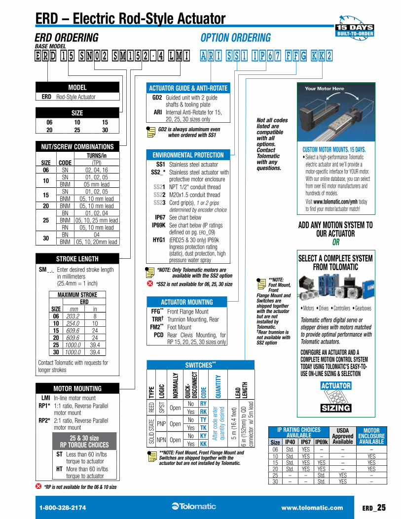
ERD – Electric Rod-Style ActuatorERD ORDERING OPTION ORDERING
Not all codes listed are compatible with all options. Contact Tolomatic with any questions.
BASE MODEL
moDElERD Rod-Style Actuator
motoR mouNtiNGlmi In-line motor mount
RP1* 1:1 ratio, Reverse Parallel motor mount
RP2* 2:1 ratio, Reverse Parallel motor mount
25 & 30 size RP toRQuE cHoicES
St Less than 60 in/lbs torque to actuator
Ht More than 60 in/lbs torque to actuator
*RP is not available for the 06 & 10 size
ENviRoNmENtAl PRotEctioNSS1 Stainless steel actuator
SS2_* Stainless steel actuator with protective motor enclosure
SS21 NPT 1/2" conduit threadSS22 M20x1.5 conduit threadSS23 Cord grip(s), 1 or 2 grips
determined by encoder choiceiP67 See chart below
iP69k See chart below (iP ratings defined on pg. eRd_09)
HyG1 (eRd25 & 30 only) IP69k Ingress protection rating (static), dust protection, high pressure water spray
ActuAtoR GuiDE & ANti-RotAtEGD2 Guided unit with 2 guide
shafts & tooling plateARi Internal anti-Rotate for 15,
20, 25, 30 sizes only
GD2 is always aluminum even
when ordered with SS1
ActuAtoR mouNtiNGFFG** Front Flange MounttRR† Trunnion Mounting, Rear
Fm2** Foot MountPcD Rear Clevis Mounting, for
RP 15, 20, 25, 30 sizes only
StRokE lENGtHSm _ _._ enter desired stroke length
in millimeters (25.4mm = 1 inch)
mAXimum StRokE
SiZEERD
mm in06 203.2 810 254.0 1015 609.6 2420 609.6 2425 1000.0 39.430 1000.0 39.4
Contact Tolomatic with requests for longer strokes
Nut/ScREW comBiNAtioNS
SiZE coDEtuRNS/in
(tPI)06 SN 02, 04, 16
10 SN 01, 02, 05BNM 05 mm lead
15 SN 01, 02, 05BNM 05, 10 mm lead
20 BNM 05, 10 mm lead
25Bn 01, 02, 04
BNM 05, 10, 25 mm leadRn 05, 10 mm lead
30 Bn 04BNM 05, 10, 20mm lead
SiZE06 10 1520 25 30
ERD 15 SN02 SM152.4 LMI ARI SS1 IP67 FFG kk2
SWitcHES**
tyPE
loGi
c
NoRm
Ally
Quic
k-Di
ScoN
NEct
coDE
QuAN
tity
lEAD
lE
NGtH
Reed
SPST Open
no Ry
afte
r cod
e en
ter
quan
tity
desir
ed
5 m
(16.
4 fe
et)
6 in
(152
mm
) to
Qd
conn
ecto
r w/
5m
lead
yes Rk
SOLiD
STA
TE PnP Openno tyyes tk
nPn Openno kyyes kk
**NOTE: Foot Mount, Front
Flange Mount and Switches are shipped together with the actuator but are not installed by Tolomatic.†Rear trunnion is not available with SS2 option
**NOTE: Foot Mount, Front Flange Mount and Switches are shipped together with the actuator but are not installed by Tolomatic.
*NOTE: Only Tolomatic motors are
available with the SS2 option
*SS2 is not available for 06, 25, 30 size
SElEct A comPlEtE SyStEm FRom tolomAtic
ADD ANy motioN SyStEm to ouR ActuAtoR
OR
cuStom motoR mouNtS. 15 DAyS. • Select a high-performance Tolomatic
electric actuator and we’ll provide a motor-specific interface for yOuR motor. With our online database, you can select from over 60 motor manufacturers and hundreds of models.
Visit www.tolomatic.com/ymh today to find your motor/actuator match!
• Motors • Drives • Controllers • Gearboxes
Tolomatic offers digital servo or stepper drives with motors matched to provide optimal performance with Tolomatic actuators.
coNFiGuRE AN ActuAtoR AND A comPlEtE motioN coNtRol SyStEm toDAy uSiNG tolomAtic’S EASy-to-uSE oN-liNE SiZiNG & SElEctioN
SIZING
ACTUATOR
iP RAtiNG cHoicES AvAilABlE
uSDA Approved Available
motoR ENcloSuRE AvAilABlESize iP40 iP67 iP69k
06 Std. yES – – –10 Std. yES – – yES15 Std. yES yES – yES20 Std. yES yES – yES25 – – Std. yES –30 – – Std. yES –
©2013 TOLOMATIC
8All brand and product names are trademarks or registered trademarks of their respective owners. Information in this document is believed accurate at time of printing. However, Tolomatic assumes no responsibility for its use or for any errors that may appear in this document. Tolomatic reserves the right to change the design or operation of the equipment described herein and any associated motion products without notice. Information in this document is subject to change without notice.
Visit www.tolomatic.com for the most up-to-date technical information
3800 County Road 116 • Hamel, MN 55340 U.S.A. Phone: (763) 478-8000 • Fax: (763) 478-8080
Toll-Free: 1-800-328-2174 Email: [email protected] • http://www.tolomatic.com
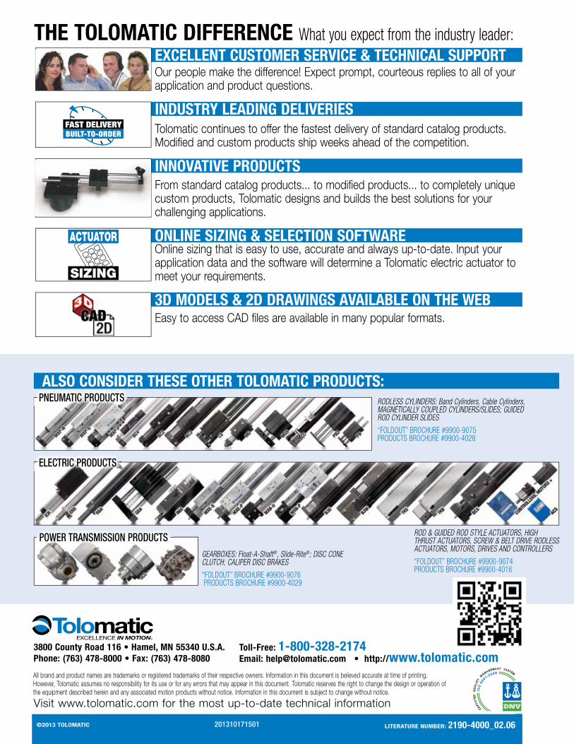
THE TOLOMATIC DIFFERENCE What you expect from the industry leader:EXCELLENT CUSTOMER SERVICE & TECHNICAL SUPPORTOur people make the difference! Expect prompt, courteous replies to all of your application and product questions.
INDUSTRY LEADING DELIVERIESTolomatic continues to offer the fastest delivery of standard catalog products. Modified and custom products ship weeks ahead of the competition.
INNOVATIVE PRODUCTSFrom standard catalog products... to modified products... to completely unique custom products, Tolomatic designs and builds the best solutions for your challenging applications.
SIZING
ACTUATOR ONLINE SIZING & SELECTION SOFTWAREOnline sizing that is easy to use, accurate and always up-to-date. Input your application data and the software will determine a Tolomatic electric actuator to meet your requirements.
3D MODELS & 2D DRAWINGS AVAILABLE ON THE WEBEasy to access CAD files are available in many popular formats.
POWER TRANSMISSION PRODUCTS
ELECTRIC PRODUCTS
PNEUMATIC PRODUCTS RODLESS CYLINDERS: Band Cylinders, Cable Cylinders, MAGNETICALLY COUPLED CYLINDERS/SLIDES; GUIDED ROD CYLINDER SLIDES
“FOLDOUT” BROCHURE #9900-9075 PRODUCTS BROCHURE #9900-4028
ROD & GUIDED ROD STYLE ACTUATORS, HIGH THRUST ACTUATORS, SCREW & BELT DRIVE RODLESS ACTUATORS, MOTORS, DRIVES AND CONTROLLERS
“FOLDOUT” BROCHURE #9900-9074 PRODUCTS BROCHURE #9900-4016
GEARBOXES: Float-A-Shaft®, Slide-Rite®; DISC CONE CLUTCH; CALIPER DISC BRAKES
“FOLDOUT” BROCHURE #9900-9076 PRODUCTS BROCHURE #9900-4029
ALSO CONSIDER THESE OTHER TOLOMATIC PRODUCTS:
201310171501 litERAtuRE NumBER: 2190-4000_02.06