Embed Size (px)
Citation preview
Electric motors forhazardous locations
R o t a t i n g E l e c t r i c a l M a c h i n e s
2203E
Technical section
Brook Crompton
Brook Crompton is a leading manufacturer
of electric motors for the global industrial
market, with motor solutions which benefit
a wide range of customers.
Our products are used in almost every
industrial activity including water treatment,
building services, chemical/petrochemicals,
general processing and manufacturing
where they drive fans, pumps, compressors
and conveyors, amongst other things.
Brook Crompton incorporates many well
known names including Brook Motors,
Crompton Parkinson, Electrodrives,
Newman, Bull Electric and Hawker Siddeley
Electric Motors.
We have extensive stocks of motors around
the world, backed-up by a network of
distributors, ensuring excellent local
support wherever needed.
We have over 90 years’ technical and design
experience in this most specialised market and
are able to ensure the correct selection of
motors for any application, taking into full
account the two most important factors to be
considered – safety and economy.
All motors are of the highest quality, built to the
latest national and International standards and
certified by the relevant national authorities for
use in almost every country.
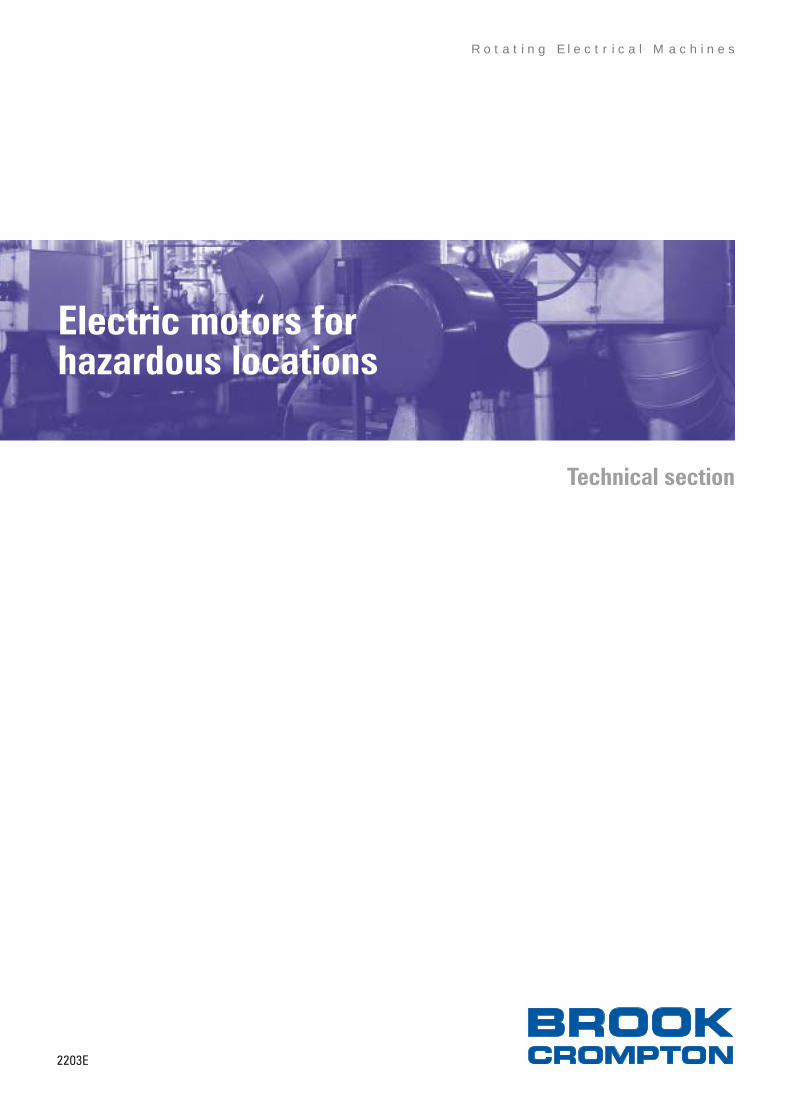
The motors are operating in hostile
environments throughout the world, on
offshore oil and gas rigs and production
platforms, onshore terminals, oil refineries,
chemical works, coal mines and petrol stations,
safely and efficiently delivering power with
minimal attention over long periods.
Oil refineries in Abu Dhabi, chemicals and
aromatics plants in Malaysia and the world’s
largest grain terminal in China are just a few of
the recent projects in which we have been
involved with the major energy companies,
main specifiers and contractors – testimony
enough to the expertise and reputation of the
motors we manufacture and to the people
who make it all work.
Quality assurance
Stringent quality procedures are observed
from first design to finished product in
accordance with the ISO9001 documented
quality systems.
All of our factories have been assessed to
meet these requirements, a further
assurance that only the highest possible
standards of quality are accepted.
The W range
This catalogue includes the ‘W’ range of
motors, the result of a major development
programme which involved a fundamental
redesign. The principal design objective was
low lifetime cost. This is achieved by high
efficiency for reduced energy consumption,
ease of installation and low maintenance
requirements.
Benefits include:
• higher efficiency – lower running costs
• low noise levels
• ‘Eurovoltage’ – 400 volts ± 10% 50Hz
• dual frequency – 50Hz and 60Hz details on
stock motors
• high power factors
• high torque with smooth acceleration and
low current
• ease of maintenance
• IP55 protection
• IEC, NEMA and Japanese standards
• Multi-Mount versatility
• simple foot to flange conversion
• up to sixteen cable entry positions
• large easy access diagonally split terminal
box
• clean modern lines
• full two year guarantee
Efficiency
Brook Crompton are an approved
manufacturer of ac electric motors within the
UK Government’s Enhanced Capital
Allowance scheme (ECA). A wide range of
single and multi-speed motors are included
on the UK Energy Technology List. Please
check the ECA scheme website:
www.eca.gov.uk at time of purchase for
current listing.
2
2203E Issue 1 Electric motors for hazardous locations
Electric motors for hazardous locations
Special projects division
The special projects division provides a fully
comprehensive service at all stages of
turnkey development. Our experience in
special engineering projects extends
throughout the world and embraces natural
resource exploration, refining, power
generation, raw material manufacture, food
processing and transport engineering.
Our team of project co-ordinators have in-
depth knowledge and experience of
handling this type of work. Informed and
technical advice is available from initial
exploratory enquiries and carefully followed
through to completion of contract. Liaison
with main and sub-contracting companies,
investigating special technical and
commercial requirements, submission of
proposals and, of course, competitive
estimates are all part of the very special
service we offer.
Our reputation has been built on the
experience and customer satisfaction gained
through involvement with a number of most
impressive international and UK-based
projects. This includes many different plant
applications for some of the world’s leading
industrial companies. Recent examples of
our success in this field are listed opposite:
Oil & GasContractorJGCKvaerner Oil & GasLG/Lurgi ConsortiumSnamprogettiSnamprogettiSNC LavalinKvaerner Oil & GasTerra Nova AllianceChiyoda/Foster WheelerJGC/Kellogg JVBrown & RootDaelim EngineeringBrown & RootAMECAMECEngineers IndiaBrown & RootBrown & Root/Aker EngineeringR M ParsonsAMECTechnip ItalyAMECSnamprogettiBechtel/SnamprogettiParsons/Fluor Daniel
Chemicals and petrochemicalsKerteh - MalaysiaKerteh - MalaysiaFertiliser Plant - VenezuelaPTA Plant - PakistanPTA Plant - Saudi ArabiaAlpha-Alcohols Plant - ChinaSriracha Base Oil - ThailandPTA Plant - IndonesiaPharmaceuticals - IrelandPharmaceuticals - SingaporeMoerdijk - NetherlandsSeal Sands - UKSeraya - SingaporeSwords Laboratories - IrelandPharmaceuticals - SingaporeAvon - Bristol
Aromatics MalaysiaVinyl Chloride (Malaysia)Pequiven-KochDuPontArabian Industrial FibresJilin Chemical IndThai Lube Base CoPetrokemaWyeth-AyerstPfizer/Parke DavisShell Chemie BVIneos AcrylicsSeraya ChemicalsBristol Myers SquibbSchering PloughAstra Zeneca
General
Grain Terminal - ChinaOffshore Patrol Vessels - UKAurora Cruise Liner - GermanyGold Mine - KyrgystanMafraq Water Treatment - UAEJubilee Line - UKCaracas Metro - VenezuelaPaper Mill - UKCement Plant - QatarKwang Yang Steel Works - KoreaSludge Drying Plant - ScotlandNagasaki Shipyard - JapanPuma & Lynx Engine Plants - UKEngine Plants - UK & Germany
Dalian Xizui Grain TerminalRoyal Brunei NavyP & O Cruise LinersKumtor GoldGovernmentLondon UndergroundC A Metro de CaracasBridgewater PaperQNCCPohang Iron & SteelScottish WaterP & O Cruise LinersFord Motor CoGeneral Motors
Power
Ling Ao Power Station - ChinaPower Station - TaiwanSual Power Station - PhilippinesSeraya Power Station - SingaporeTamnin - MexicoKangol - TurkeyCan - TurkeyManjung - Malaysia
Ling Ao Nuclear PowerHo-Ping PowerPangasinan Electrical CoPublic Utilities BoardTEGTEKTurkish ElectricityTNB Janamanjng
ClientAramcoTexacoNODCOADNOCADNOCLukoilAmerada HessPetro-CanadaOman LNGRas Laffan LNG CoBPNational Iranian GasChevronShellConocoONGCBHP PetroleumPhillipsStatoilShell NigeriaSaudi AramcoSaudi AramcoLasmo OilBG/Agip/Lukoil Tengizchevroil
Plant/locationHawaya Natural Gas - Saudi ArabiaCaptain Field Development - North SeaNODCO Expansion Project - QatarRuwais Refinery Expansion - Abu DhabiASAB Gas Development - Abu DhabiVolgograd Refinery Modification - RussiaAbbot Field - North SeaFPSO - Offshore CanadaLNG Project - OmanLNG Plant - QatarETAP Project - North SeaCompressor Station - IranAlba Field - North SeaCurlew Field - North SeaBritannia Field - North SeaBombay High Platform - IndiaLiverpool Bay Development - Irish SeaUla Field - Norwegian North SeaKalundborg Condensate - DenmarkBonga Field - NigeriaHaradh Gas - Saudi ArabiaBerri Gas - Saudi ArabiaBhit Field - PakistanKarachaganak - KazakhstanTengiz - Kazakhstan
Toyo EngineeringToyo EngineeringSnamprogettiFoster WheelerBechtelSnamprogettiJGCKvaernerJacobs EngineeringJacobs Lend LeaseABB Lummus GlobalKvaerner EngineeringABB Lummus GlobalKvaerner ProcessFoster WheelerJacobs Engineering
ASC Materials HandlingYarrow ShipbuildersMeyer WerftKilborn - ENKABi-waterDrake & SkullMetro de Caracas (In house)Fluor DanielFives-Cail BabcockDavy McKeeAndritz AGMHIFord (In house)GE Supplies
GEC Alstom PPAlstom Power PlantsGEC Alstom PPIHIAlstom AutomationMitsubishi Heavy IndAlstom PowerAlstom Energy
2203E Issue 1 Electric motors for hazardous locations
3
4
2203E Issue 1 Electric motors for hazardous locations
General
A potentially explosive atmosphere is one
which could become explosive under certain
conditions (the danger is a potential one).
An explosive atmosphere is one where a
mixture with air, under atmospheric
conditions of flammable substances in the
form of gas, vapour, mist or dusts exist in
such proportions that they can be ignited by
excessive temperature, arcs or sparks (the
danger is a real one).
Safety
Safety is of paramount importance in the
use of electrical equipment in flammable or
potentially flammable atmospheres. Correct
selection of motors for hazardous
atmospheres is therefore essential, bearing
in mind the economics of the various types
of motor available.
The notes which follow are taken mainly
from the CENELEC/EURONORM standards
EN 50 014 and EN 50 018. Reference is
made to other standards where applicable.
ATEX
ATEX (ATmosphères EXplosible) is the
European Directive 94/9/EC. It applies to all
equipment either electrical or mechanical
used in hazardous atmospheres both dust
and gas. The directive was introduced in
1994 and allowed a ten year period for
introduction. All equipment manufactured
after 30 June 2003 must comply with ATEX.
The main purpose is to remove barriers to
trade throughout the European Community.
It also lays down specific requirements for
users of such equipment.
The essential elements of ATEX involve:-
Notified Bodies, Standards, Conformity
Assessment, Marking and Documentation.
The ATEX Directive is complementary to
other directives such as Machinery
Directive, Low Voltage Directive and
Electromagnetic Compatibility. To show
compliance with any of these directives,
equipment is CE-marked accordingly. It is
further complemented by the ‘USE’
Directive (1999/92/EC) which sets down the
requirements for the safety and health
protection of workers potentially at risk from
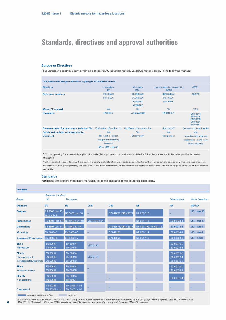
explosive atmospheres.
Notified Bodies
These were previously referred to as Testing
Authorities. European Notified Body provides
Brook Crompton’s ATEX approval and
certification to the appropriate standard. This
includes category 2 and 3 equipment even
though the latter could be self certified.
Standards
Standards must be current. This may mean,
as with dust, entirely new standards. In the
case of others, eg EEx d motors, the
standards have remained the same in
substance – the latest editions contain only
small detail changes.
Zones
Equipment categories
Equipment categories are another change
which has been introduced. Equipment will
now have a category number appropriate to
the Zone for which it is intended to operate
(see table on page 5).
Zones remain the same as previously for gas
but in the case of dust, a new system using
Zones 20, 21 and 22, has been introduced.
Certification
Certification by a Notified Body is only
mandatory for equipment categories 1 and
2. For category 3 equipment manufacturers
are allowed to issue their own certificate of
compliance. Our motors for category 3
however will have a type examination
certificate issued by EECS/BASEEFA.
Conformity assessment
A process identical with the current
certification procedure. In addition Quality
Assessment (or Verification module) is
carried out by a Notified Body - in our case
EECS/BASEEFA.
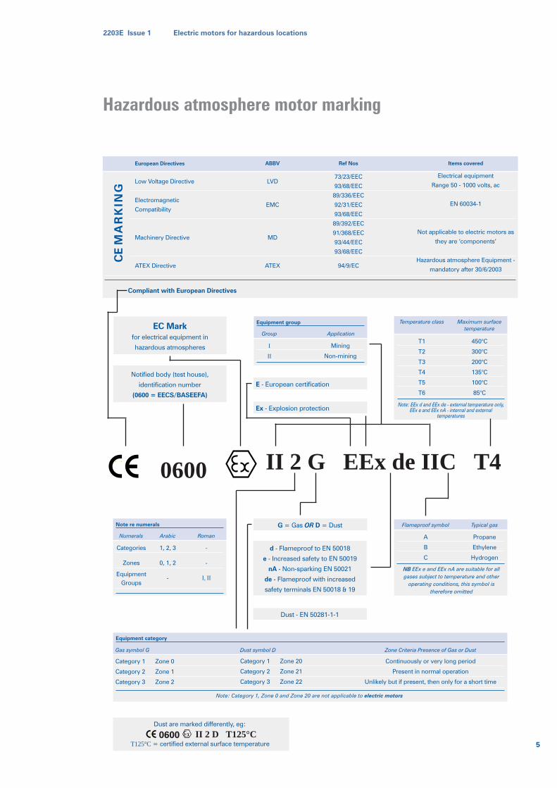
Marking
This is the area of greatest visible change
and is detailed on opposite page. Motors for
gas hazards will contain the familiar marking
(EEx de IIC T4 for example) preceded by a
string of symbols (see opposite page).
Documentation
Specific installation and maintenance
instructions are a mandatory part of
obtaining approval and must be supplied for
ATEX equipment.
CENELEC/Euronorm standards
Before the existence of these standards, each
country had its own national standards. The
EU member countries now have a common
standard for flameproof motors: EN 50 014
and EN 50 018. The standard can be certified
by any of the notified bodies (certifying
authorities) of the member countries. These
motors are therefore acceptable in all EU
countries and most other European
countries. Countries outside Europe which
often base their standards on British
Standards are expected to follow in due
course.
Motors thus certified are prefixed EEx –
eg flameproof motors, EEx d.
ATEX Directive 94/9/EC
2203E Issue 1 Electric motors for hazardous locations
5
Hazardous atmosphere motor marking
EC Markfor electrical equipment in
hazardous atmospheres
European Directives
Low Voltage Directive
Electromagnetic
Compatibility
Machinery Directive
ATEX Directive
LVD
EMC
MD
ATEX
ABBV
73/23/EEC
93/68/EEC
89/336/EEC
92/31/EEC
93/68/EEC
89/392/EEC
91/368/EEC
93/44/EEC
93/68/EEC
94/9/EC
Ref Nos
Electrical equipment
Range 50 - 1000 volts, ac
EN 60034-1
Not applicable to electric motors as
they are ‘components’
Hazardous atmosphere Equipment -
mandatory after 30/6/2003
Items covered
CE
MA
RK
ING
Notified body (test house),
identification number
(0600 = EECS/BASEEFA)
d - Flameproof to EN 50018
e - Increased safety to EN 50019
nA - Non-sparking EN 50021
de - Flameproof with increased
safety terminals EN 50018 & 19
E - European certification
Ex - Explosion protection
G = Gas OR D = Dust
Equipment group
Group
I
II
Mining
Non-mining
Application
Equipment category
Gas symbol G
Category 1 Zone 0
Category 2 Zone 1
Category 3 Zone 2
Dust symbol D
Category 1 Zone 20
Category 2 Zone 21
Category 3 Zone 22
Zone Criteria Presence of Gas or Dust
Continuously or very long period
Present in normal operation
Unlikely but if present, then only for a short time
Temperature class
Note: EEx d and EEx de - external temperature only,EEx e and EEx nA - internal and external
temperatures
T1
T2
T3
T4
T5
T6
450°C
300°C
200°C
135°C
100°C
85°C
Maximum surfacetemperature
Flameproof symbol
NB EEx e and EEx nA are suitable for allgases subject to temperature and other
operating conditions, this symbol istherefore omitted
Note: Category 1, Zone 0 and Zone 20 are not applicable to electric motors
A
B
C
Propane
Ethylene
Hydrogen
Typical gas
II 2 G EEx de IIC T40600
Note re numerals
Numerals
Categories
Zones
EquipmentGroups
Arabic
1, 2, 3
0, 1, 2
-
Roman
-
-
I, II
Compliant with European Directives
Dust - EN 50281-1-1
Dust are marked differently, eg:
II 2 D T125°CT125°C= certified external surface temperature
0600
standard motor complies optional
European Directives
Four European directives apply in varying degrees to AC induction motors. Brook Crompton comply in the following manner:-
StandardsHazardous atmosphere motors are manufactured to the standards of the countries listed below.
Range UK European
National standard
International North American
Standard
Outputs
Performance
Dimensions
Mounting
Degrees of IP protection
EEx d
Flameproof
EEx de
Flameproof with
increased safety terminals
EEx e
Increased safety
EEx nA
Non-sparking
Dust hazard
BS
BS 5000 part 10,
appendix A
BS 4999 Part 101
BS 4999 part 141
EN 60034-7
EN 60034-5
EN 50014
EN 50018
EN 50014
EN 50018
EN 50019
EN 50014
EN 50019
EN 50014
EN 50021
EN 50281 - 1-1
EN 50281 - 1-2
EN 50014
EN 50018
EN 50014
EN 50018
EN 50019
EN 50014
EN 50019
EN 50014
EN 50021
EN 50281 - 1-1
EN 50281 - 1-2
BS
BS 5000 part 10
BS 4999 part 101
as DIN and NF
EN 60034-7
EN 60034-5
VDE
–
VDE 0530 part 1
–
–
–
DIN
DIN 42673, DIN 42677
–
DIN 42673, DIN 42677
DIN 42950
DIN 40050
–
–
–
–
–
NF
NF C51-110
NF C51-111
NF C51-105, NF C51-120
NF C51-117
NF C51-115
–
–
–
–
–
IEC
–
IEC 60034-1
IEC 60072-1
IEC 60034-7
IEC 60034-5
IEC 60079-0
IEC 60079-1
IEC 60079-0
IEC 60079-1
IEC 60079-7
IEC 60079-0
IEC 60079-7
IEC 60079-15
–
NEMA*
MG1 part 10
MG1 part 12
MG1 part 4
MG1 part 4
MG1-1.26B
–
–
–
–
–
Standards
VDE 0171
VDE 0171
–
–
–
6
2203E Issue 1 Electric motors for hazardous locations
Standards, directives and approval authorities
Reference numbers
Motor CE marked
Standards
Documentation for customers’ technical file
Safety instructions with every motor
Comment
Compliance with European directives applying to AC induction motors
73/23/EEC
93/68/EEC
Yes
EN 60034
Declaration of conformity
Yes
Relevant electrical
equipment operating
between
50 to 1000 volts AC
Directives Low voltage(LV)
89/392/EEC
91/368/EEC
93/44/EEC
93/68/EEC
No
Not applicable
Certificate of incorporation
Yes
Statement(2)
Machinery(MD)
89/336/EEC
92/31/EEC
93/68/EEC
No
EN 60034-1
Statement(1)
Yes
Component
Electromagnetic compatibility(EMC)
(1) Motors operating from a correctly applied, sinusoidal (AC) supply meet the requirements of the EMC directive and are within the limits specified in standard
EN 60034-1(2) When installed in accordance with our customer safety and installation and maintenance instructions, they can be put into service only when the machinery into
which they are being incorporated, has been declared to be in conformity with the machinery directive in accordance with Article 4(2) and Annex IIB of that Directive
(98/37/EEC)
94/9/EC
YES
EN 50014EN 50018EN 50019EN 50021EN 50281
Declaration of conformity
Yes
Hazardous atmosphere
equipment - mandatory
after 30/6/2003
ATEX
Motors complying with IEC 60034-1 also comply with many of the national standards of other European countries, eg CEI 203 (Italy), NBN7 (Belgium), NEN 3173 (Netherlands),SEN 2601 01 (Sweden) *Motors to NEMA standards have CSA approval and generally comply with Canadian (EEMAC) standards.
IEC standard 60079
This gives practical help in the selection,
installation and maintenance of electrical
apparatus for use in potentially explosive
atmospheres. It deals with the installation
and maintenance requirements appropriate
to one of the types of protection that may
be used to achieve electrical safety or with
basic requirements and considerations that
are fundamental to the use of electrical
apparatus in potentially explosive
atmospheres. The parts which concern
electric motors are:
EN 60079 – 14 – Types d and e.
The classification of hazardous areas is
detailed in EN 60079.
Dust hazards are detailed in EN 50281-1-1
EN 50281-1-2
Approval Authorities
European
EECS/BASEEFA and MECS
Approvals are through the Electrical
Equipment Certification Service (EECS) of the
Health and Safety Laboratory based at
Buxton, England or other notified bodies.
This service covers approvals by
EECS/BASEEFA, the Electrical Equipment
Certification Service/British Approvals
Service for Electrical Equipment in
Flammable Atmospheres which is a notified
body for all types of motors for use in
hazardous atmospheres in surface industries.
MECS, is the Mining Equipment Certification
Service for motors in mines.
Both BASEEFA and MECS issue certificates
stating that equipment meets the
requirements laid down in EURONORM
Standards, these supersede the formerly
recognised ‘Buxton’ certificate.
Mines
For mines susceptible to firedamp, flameproof
motors enclosure Group I designated and
marked MEx are used (formerly FLP).
Australian
NSW – New South Wales Mines Approval is
held and motors to AS 2380.2–1991, and
certificate Ex 230 for non-mining
applications.
South African
Certified motors for both industry and mines
can be supplied.
S. Commission
Motors for S Commission (former
Yugoslavian territories). We can supply
EEx de motors with increased safety
terminals fitted with sealing chamber as
required by the S Commission.
North American standards
Hazardous location electrical equipment is
dealt with in:
USA: by the National Electrical Code –
NEC articles 500 to 516.
Canada: by the Canadian Electrical Code –
C22.1 – Part 1 – Section 18.
Canadian
CSA – Canadian Standards Association.
Motors with CSA approval to imperial or
metric dimensions are available. These are
certified for Class 1 Division 1 or Class 1
Division II.
NB CSA motors are often acceptable in the
USA. EMR – Energy, Mines and Resources
Canada – certified motors are available.
German
PTB – Physikalisch-Technische Bundes-anstalt
certify a full range of flameproof (pressure-
tight) motors to German Standard VDE
0171/2-61 can be supplied.
Russian
Motors certified by Glavgosenergonadzor
(State Power Inspectorate Body) for general
surface use can be supplied.
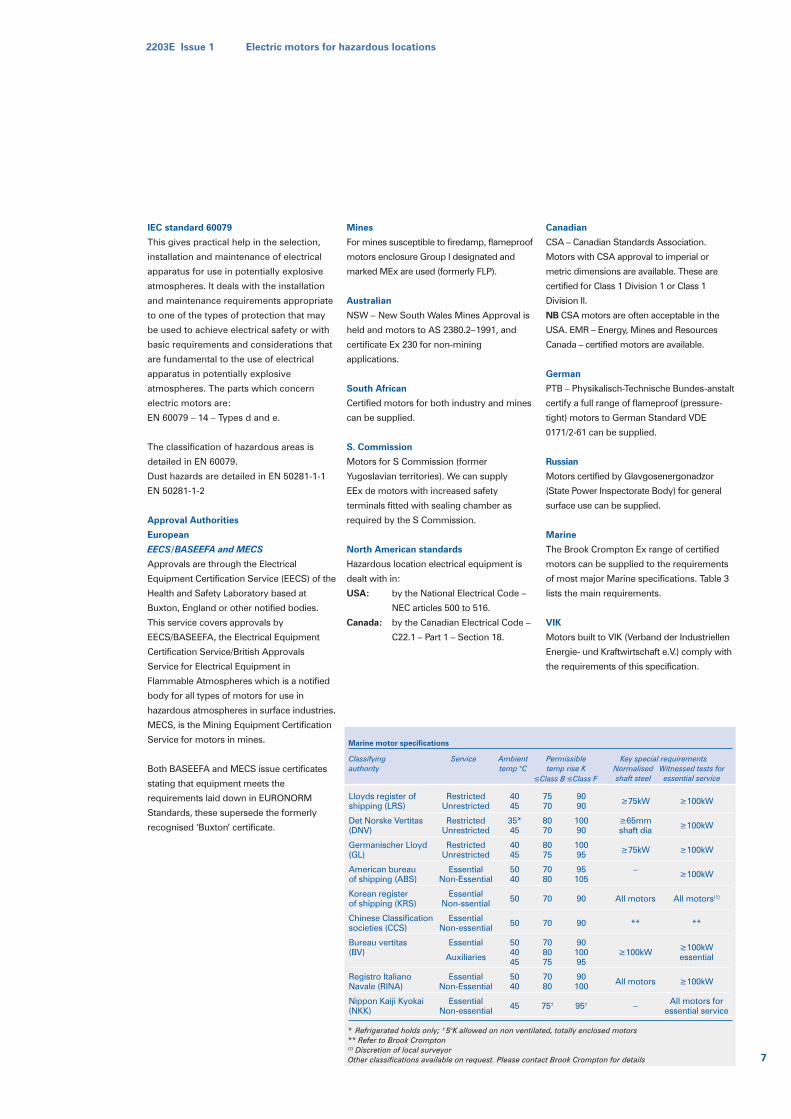
Marine
The Brook Crompton Ex range of certified
motors can be supplied to the requirements
of most major Marine specifications. Table 3
lists the main requirements.
VIK
Motors built to VIK (Verband der Industriellen
Energie- und Kraftwirtschaft e.V.) comply with
the requirements of this specification.
Marine motor specifications
Classifyingauthority
Lloyds register ofshipping (LRS)
Det Norske Vertitas(DNV)
Germanischer Lloyd(GL)
American bureauof shipping (ABS)
Korean registerof shipping (KRS)
Chinese Classificationsocieties (CCS)
Bureau vertitas(BV)
Registro ItalianoNavale (RINA)
Nippon Kaiji Kyokai(NKK)
RestrictedUnrestricted
RestrictedUnrestricted
RestrictedUnrestricted
EssentialNon-Essential
EssentialNon-ssential
EssentialNon-essential
Essential
Auxiliaries
EssentialNon-Essential
EssentialNon-essential
4045
35*45
4045
5040
50
50
504045
5040
45
7570
8070
8075
7080
70
70
708075
7080
75†
9090
10090
10095
95105
90
90
9010095
90100
95†
≥75kW
≥65mmshaft dia
≥75kW
–
All motors
**
≥100kW
All motors
–
≥100kW
≥100kW
≥100kW
≥100kW
All motors(1)
**
≥100kWessential
≥100kW
All motors foressential service
Service Ambienttemp °C
Permissibletemp rise K
≤Class B ≤Class FNormalisedshaft steel
Witnessed tests foressential service
Key special requirements
* Refrigerated holds only; † 5°K allowed on non ventilated, totally enclosed motors** Refer to Brook Crompton(1) Discretion of local surveyorOther classifications available on request. Please contact Brook Crompton for details
2203E Issue 1 Electric motors for hazardous locations
7
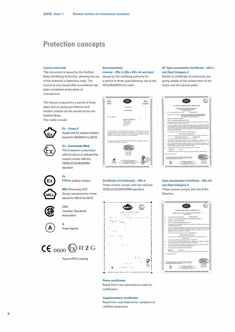
Licence and mark
This document is issued by the Notified
Body (Certifying Authority), allowing the use
of the Authority’s distinctive mark. The
licence is only issued after surveillance has
been completed at the place of
manufacture.
The licence is issued for a period of three
years and on-going surveillance and
random checks can be carried out by the
Notified Body.
The marks include:
Ex – Group II
Equipment for surface industry
issued for BASEEFA by EECS
Ex – Community Mark
This is issued in conjunction
with the above to indicate that
motors comply with the
CENELEC/EURONORM
standard
Ex
PTB for surface industry
MEx (Previously FLP)
Group I equipment for mines
issued for MECS by EECS
CSA
Canadian Standards
Association
A
Trade Agents
Typical ATEX marking
Documentation
Licence – EEx d, EEx e EEx nA and dust
Issued by the certifying authority for
a period of three years allowing use of the
EECS/BASEEFA Ex mark.
Certificate of Conformity – EEx d
These motors comply with the relevant
CENELEC/EURONORM standard.
Prime certificates
Result from new submissions made for
certification.
Supplementary certificates
Result from submissions for variations of
certified equipment.
EC Type examination Certificate – EEx e
and Dust Category 2
Similar to certificate of conformity, but
giving details of the construction of the
motor and the various parts.
Type examination Certificate – EEx nA
and Dust Category 3
These motors comply with the ATEX
Directive.
Ex
MEx
Ex
A
Protection concepts
II 20600 G
8
2203E Issue 1 Electric motors for hazardous locations
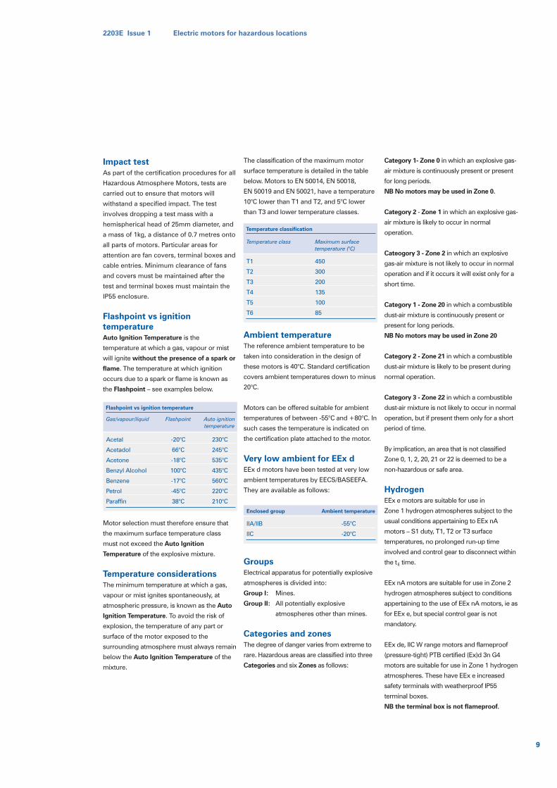
Impact testAs part of the certification procedures for all
Hazardous Atmosphere Motors, tests are
carried out to ensure that motors will
withstand a specified impact. The test
involves dropping a test mass with a
hemispherical head of 25mm diameter, and
a mass of 1kg, a distance of 0.7 metres onto
all parts of motors. Particular areas for
attention are fan covers, terminal boxes and
cable entries. Minimum clearance of fans
and covers must be maintained after the
test and terminal boxes must maintain the
IP55 enclosure.
Flashpoint vs ignitiontemperatureAuto Ignition Temperature is the
temperature at which a gas, vapour or mist
will ignite without the presence of a spark or
flame. The temperature at which ignition
occurs due to a spark or flame is known as
the Flashpoint – see examples below.
Motor selection must therefore ensure that
the maximum surface temperature class
must not exceed the Auto Ignition
Temperature of the explosive mixture.
Temperature considerationsThe minimum temperature at which a gas,
vapour or mist ignites spontaneously, at
atmospheric pressure, is known as the Auto
Ignition Temperature. To avoid the risk of
explosion, the temperature of any part or
surface of the motor exposed to the
surrounding atmosphere must always remain
below the Auto Ignition Temperature of the
mixture.
The classification of the maximum motor
surface temperature is detailed in the table
below. Motors to EN 50014, EN 50018,
EN 50019 and EN 50021, have a temperature
10°C lower than T1 and T2, and 5°C lower
than T3 and lower temperature classes.
Ambient temperatureThe reference ambient temperature to be
taken into consideration in the design of
these motors is 40°C. Standard certification
covers ambient temperatures down to minus
20°C.
Motors can be offered suitable for ambient
temperatures of between -55°C and +80°C. In
such cases the temperature is indicated on
the certification plate attached to the motor.
Very low ambient for EEx dEEx d motors have been tested at very low
ambient temperatures by EECS/BASEEFA.
They are available as follows:
GroupsElectrical apparatus for potentially explosive
atmospheres is divided into:
Group I: Mines.
Group II: All potentially explosive
atmospheres other than mines.
Categories and zonesThe degree of danger varies from extreme to
rare. Hazardous areas are classified into three
Categories and six Zones as follows:
Category 1- Zone 0 in which an explosive gas-
air mixture is continuously present or present
for long periods.
NB No motors may be used in Zone 0.
Category 2 - Zone 1 in which an explosive gas-
air mixture is likely to occur in normal
operation.
Cateogory 3 - Zone 2 in which an explosive
gas-air mixture is not likely to occur in normal
operation and if it occurs it will exist only for a
short time.
Category 1 - Zone 20 in which a combustible
dust-air mixture is continuously present or
present for long periods.
NB No motors may be used in Zone 20
Category 2 - Zone 21 in which a combustible
dust-air mixture is likely to be present during
normal operation.
Category 3 - Zone 22 in which a combustible
dust-air mixture is not likely to occur in normal
operation, but if present them only for a short
period of time.
By implication, an area that is not classified
Zone 0, 1, 2, 20, 21 or 22 is deemed to be a
non-hazardous or safe area.
HydrogenEEx e motors are suitable for use in
Zone 1 hydrogen atmospheres subject to the
usual conditions appertaining to EEx nA
motors – S1 duty, T1, T2 or T3 surface
temperatures, no prolonged run-up time
involved and control gear to disconnect within
the tE time.
EEx nA motors are suitable for use in Zone 2
hydrogen atmospheres subject to conditions
appertaining to the use of EEx nA motors, ie as
for EEx e, but special control gear is not
mandatory.
EEx de, IIC W range motors and flameproof
(pressure-tight) PTB certified (Ex)d 3n G4
motors are suitable for use in Zone 1 hydrogen
atmospheres. These have EEx e increased
safety terminals with weatherproof IP55
terminal boxes.
NB the terminal box is not flameproof.
Flashpoint vs ignition temperature
Gas/vapour/liquid
Acetal
Acetadol
Acetone
Benzyl Alcohol
Benzene
Petrol
Paraffin
-20°C
66°C
-18°C
100°C
-17°C
-45°C
38°C
230°C
245°C
535°C
435°C
560°C
220°C
210°C
Flashpoint Auto ignitiontemperature
Enclosed group
IIA/IIB
IIC
-55°C
-20°C
Ambient temperature
Temperature classification
Temperature class
T1
T2
T3
T4
T5
T6
450
300
200
135
100
85
Maximum surfacetemperature (°C)
2203E Issue 1 Electric motors for hazardous locations
9
Sub-division and enclosure group or
apparatus group: flameproof motors
For hazardous atmospheres in surface
industry (ie not in coal mines), apparatus
Group II equipment is used. In the case of
flameproof motors -EEx d and EEx de, which
are designed to contain a gas explosion
within the motor, it is necessary to take
account of the different explosive forces and
flames which various gases produce.
Using the maximum experimental safe gap,
the standards-making bodies specify safe
working dimensions for particular gases
which are sub-divided and grouped into A, B
or C. These sub-divisions are in ascending
order of increasing explosive force/energy
levels. This means that motors eg Group IIB
are suitable for IIA also. In North American
standards, the groups are reversed compared
to European standards and this is detailed on
page 16.
The table shown on page 12, details gases
and chemical compounds together with
temperature classification and ignition
temperature. This table shows the
appropriate sub-division, apparatus or
enclosure group for flameproof motors.
Certification plate group markings -
flameproof motors
Flameproof motors are marked WITH a suffix
letter after the group symbol II to indicate the
sub-group:-
EEx d IIB T4 or
EEx de IIB T4.
(T4 relating to the T class)
Non-flameproof motors
EEx e, and EEx nA motors are totally
enclosed (TEFV or TENV) type - NOT
flameproof and NOT designed with
flamepaths. The enclosure or apparatus
groups A, B and C therefore have no
relevance to these motors - only to
flameproof EEx d and EEx de types.
In the case of EEx nA motors complying with
the requirements of EN 50021 -Electrical
apparatus with type of protection “n”, the
suffix letter A indicates non-sparking
requirements for ac motors and should not
be confused with enclosure or apparatus
groups. These motors therefore are marked
WITHOUT a suffix letter after the group
symbol II, to indicate that they are suitable for
all gases within the
T class, as follows:-
EEx nA II T3 or
EEx e II T3
Explosion tests
Flameproof motors are submitted to the
testing authority who carry out proving tests
in an explosion chamber. During these tests,
motors are filled with a gas/air mixture and
placed inside a chamber containing a similar
gas/air mixture. The gas inside the motor is
ignited by means of an electrical spark. A
number of tests are conducted and only
when the authority can witness that a
secondary explosion on the outside of the
motor will not occur, does the motor pass the
explosion test.
Type of protection for Zone 1 areas:
d flameproof
A type of protection in which the parts which
can ignite an explosive atmosphere are
placed in an enclosure which can withstand
the pressure developed during an internal
explosion of an explosive mixture and which
prevents the transmission of the explosion to
the explosive atmosphere surrounding the
enclosure.
Flameproof theory
A gap between metal surfaces or flame-path
need not be totally closed to stop the
passage of a flame. The smallest gap or
flame-path necessary to prevent the passage
of a flame varies according to the gas or
vapour involved. Gases and vapours are sub-
divided according to experimental data which
has been established to determine the
maximum experimental safe gap (MESG). In
the case of metal to metal joints in a
flameproof motor, eg endshield to frame,
these will consist of a long metal spigot fitting
into a long recess which will normally be
clamped tight by the fixing bolts.
A gap/flamepath, however, will always exist
between the shaft and the motor interior.
Safety is therefore achieved in a flameproof
motor by ensuring that all the gaps/
flamepaths in the motor can never exceed
mandatory dimensions and that the motor is
physically capable of withstanding an internal
explosion without transmitting this to the
external atmosphere.
Type of protection for Zone 1 areas:
e increased safety
The method of protection by which additional
measures are applied to electrical equipment
so as to give increased security against the
possibility of excessive temperatures and
of the occurrence of sparks and arcs during the
service life of the apparatus. It applies only to
equipment no parts of which produce sparks
or arcs or exceed the limiting temperature in
normal service.
These motors are not flameproof and not built to
withstand an internal explosion. They are
designed to ensure safety by means of a number
of special features to ensure freedom from arcs,
sparks or dangerous surface temperatures under
all conditions of operation. They resemble
standard motors in appearance, but have special
increased safety terminals within an IP55 terminal
box. The main features of the Increased Safety
motors are:
1 special attention to air gap concentricity
and clearance of all rotating parts
2 components subject to impact tests
3 temperature rise 10°C lower than the
permitted maximum for that class of
insulation
4 maximum internal or external surface
temperature T1, T2 or T3
5 compliance with tE characteristic
6 special terminal board to accommodate
specified creepage and clearances, with
non twist terminations and vibration
proof cable fixing
7 terminal box with IP55 enclosure
10
2203E Issue 1 Electric motors for hazardous locations
Protection concepts
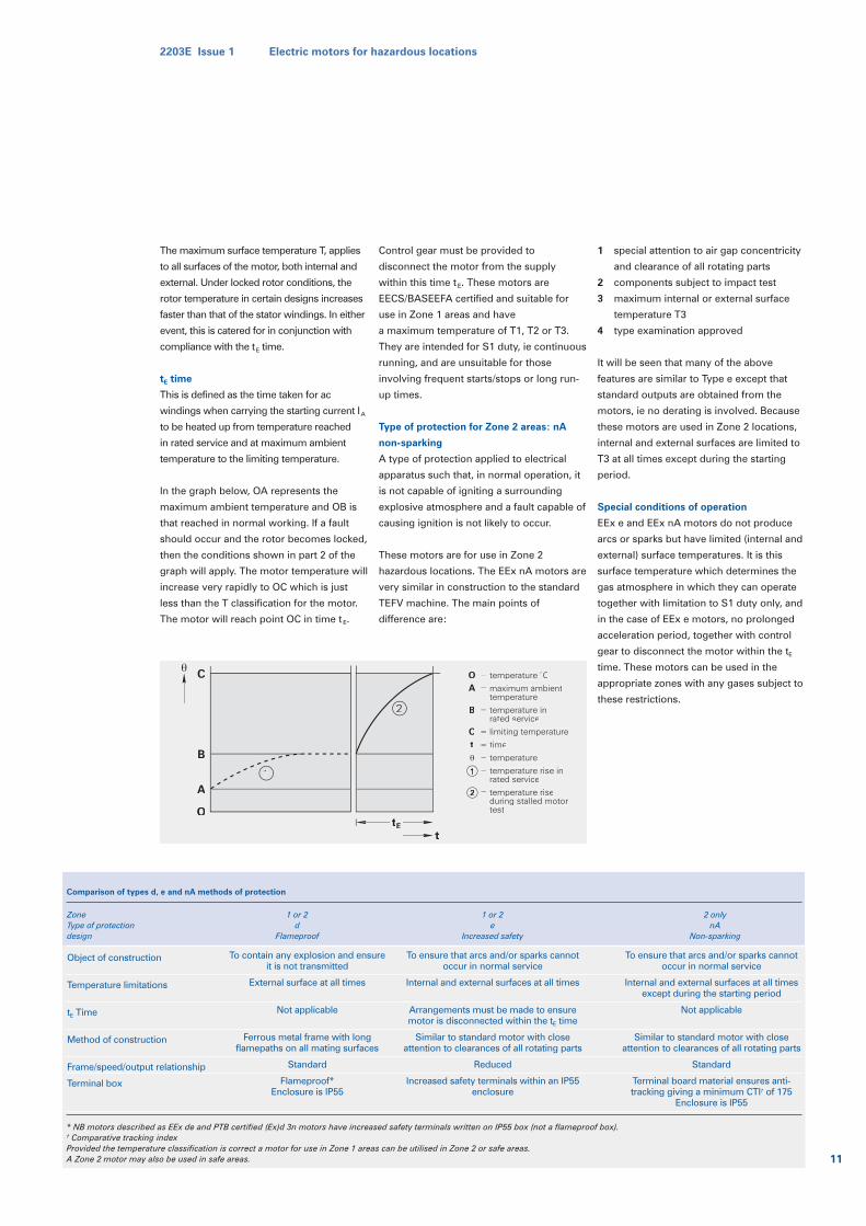
The maximum surface temperature T, applies
to all surfaces of the motor, both internal and
external. Under locked rotor conditions, the
rotor temperature in certain designs increases
faster than that of the stator windings. In either
event, this is catered for in conjunction with
compliance with the tE time.
tE time
This is defined as the time taken for ac
windings when carrying the starting current IA
to be heated up from temperature reached
in rated service and at maximum ambient
temperature to the limiting temperature.
In the graph below, OA represents the
maximum ambient temperature and OB is
that reached in normal working. If a fault
should occur and the rotor becomes locked,
then the conditions shown in part 2 of the
graph will apply. The motor temperature will
increase very rapidly to OC which is just
less than the T classification for the motor.
The motor will reach point OC in time tE.
Control gear must be provided to
disconnect the motor from the supply
within this time tE. These motors are
EECS/BASEEFA certified and suitable for
use in Zone 1 areas and have
a maximum temperature of T1, T2 or T3.
They are intended for S1 duty, ie continuous
running, and are unsuitable for those
involving frequent starts/stops or long run-
up times.
Type of protection for Zone 2 areas: nA
non-sparking
A type of protection applied to electrical
apparatus such that, in normal operation, it
is not capable of igniting a surrounding
explosive atmosphere and a fault capable of
causing ignition is not likely to occur.
These motors are for use in Zone 2
hazardous locations. The EEx nA motors are
very similar in construction to the standard
TEFV machine. The main points of
difference are:
1 special attention to air gap concentricity
and clearance of all rotating parts
2 components subject to impact test
3 maximum internal or external surface
temperature T3
4 type examination approved
It will be seen that many of the above
features are similar to Type e except that
standard outputs are obtained from the
motors, ie no derating is involved. Because
these motors are used in Zone 2 locations,
internal and external surfaces are limited to
T3 at all times except during the starting
period.
Special conditions of operation
EEx e and EEx nA motors do not produce
arcs or sparks but have limited (internal and
external) surface temperatures. It is this
surface temperature which determines the
gas atmosphere in which they can operate
together with limitation to S1 duty only, and
in the case of EEx e motors, no prolonged
acceleration period, together with control
gear to disconnect the motor within the tE
time. These motors can be used in the
appropriate zones with any gases subject to
these restrictions.
tE
t
2
1
O
C O
A
B
C
tB
A
temperature °C
maximum ambienttemperature
temperature inrated service
limiting temperature
time
temperature
temperature rise inrated service
temperature riseduring stalled motortest
=
=
=
=
=
=
=
=2
1
2203E Issue 1 Electric motors for hazardous locations
11
Comparison of types d, e and nA methods of protection
ZoneType of protectiondesign
1 or 2 d
Flameproof
1 or 2 e
Increased safety
2 onlynA
Non-sparking
Object of construction
Temperature limitations
tE Time
Method of construction
Frame/speed/output relationship
Terminal box
To contain any explosion and ensureit is not transmitted
External surface at all times
Not applicable
Ferrous metal frame with longflamepaths on all mating surfaces
Standard
Flameproof*Enclosure is IP55
To ensure that arcs and/or sparks cannotoccur in normal service
Internal and external surfaces at all times
Arrangements must be made to ensuremotor is disconnected within the tE time
Similar to standard motor with closeattention to clearances of all rotating parts
Reduced
Increased safety terminals within an IP55enclosure
To ensure that arcs and/or sparks cannotoccur in normal service
Internal and external surfaces at all timesexcept during the starting period
Not applicable
Similar to standard motor with closeattention to clearances of all rotating parts
Standard
Terminal board material ensures anti-tracking giving a minimum CTI† of 175
Enclosure is IP55
* NB motors described as EEx de and PTB certified (Ex)d 3n motors have increased safety terminals written on IP55 box (not a flameproof box).† Comparative tracking indexProvided the temperature classification is correct a motor for use in Zone 1 areas can be utilised in Zone 2 or safe areas.A Zone 2 motor may also be used in safe areas.
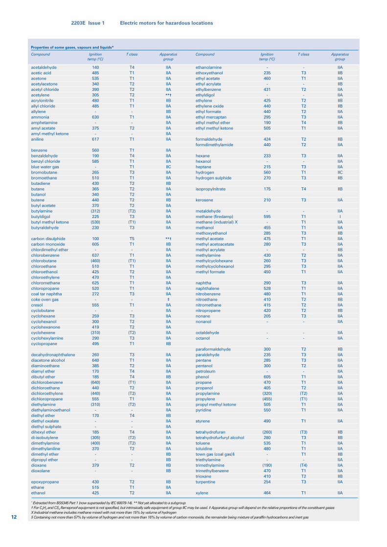
Properties of some gases, vapours and liquids*
Compound Ignitiontemp (°C)
T class Apparatusgroup
Compound Ignitiontemp (°C)
T class Apparatusgroup
acetaldehydeacetic acidacetoneacetylacetoneacetyl chlorideacetyleneacrylonitrileallyl chlorideallyleneammoniaamphetamineamyl acetateamyl methyl ketoneaniline
benzenebenzaldehydebenzyl chlorideblue water gasbromobutanebromoethanebutadienebutanebutanolbutenebutyl acetatebutylaminebutyldigolbutyl methyl ketonebutyraldehyde
carbon disulphidecarbon monoxidechlordimethyl etherchlorobenzenechlorobutanechloroethanechloroethanolchloroethylenechloromethanechloropropanecoal tar naphthacoke oven gascresolcyclobutanecyclohexanecyclohexanolcyclohexanonecyclohexenecyclohexylaminecyclopropane
decahydronaphthalenediacetone alcoholdiaminoethanediamyl etherdibutyl etherdichlorobenzenedichloroethanedichloroethylenedichloropropanediethylaminediethylaminoethanoldiethyl etherdiethyl oxalatediethyl sulphatedihexyl etherdi-isobutylenedimethylaminedimethylanilinedimethyl etherdipropyl etherdioxanedioxolane
epoxypropaneethaneethanol
140485535340390305480485
-630
-375
-617
560190585
-265510430365340440370
(312)225
(530)230
100605
-637
(460)510425470625520272
-555
-259300419
(310)290495
260640385170185
(640)440
(440)555
(310)-
170--
185(305)(400)370
--
379-
430515425
T4T1T1T2T2T2T1T1-
T1-
T2-
T1
T1T4T1T1T3T1T2T2T2T2T2
(T2)T3
(T1)T3
T5T1-
T1(T1)T1T2T1T1T1T3-
T1-
T3T2T2
(T2)T3T1
T3T1T2T4T4
(T1)T2
(T2)T1
(T2)-
T4--
T4(T2)(T2)T2--
T2-
T2T1T2
IIAIIAIIAIIAIIA**†IIBIIAIIBIIAIIAIIAIIAIIA
IIAIIAIIAIICIIAIIAIIBIIAIIAIIBIIAIIAIIAIIAIIA
**†IIBIIAIIAIIAIIAIIAIIAIIAIIAIIA‡
IIAIIAIIAIIAIIAIIAIIAIIB
IIAIIAIIAIIAIIBIIAIIAIIAIIAIIAIIAIIBIIAIIAIIAIIAIIAIIAIIBIIBIIBIIB
IIBIIAIIA
-235460
-431
-425440440295190505
424440
233-
215560270
175
210
-595
-455285475280
-430260295450
290528480410415420205
-
--
300235285300
-605470405
(320)(455)505550
490
(260)280535480
--
(190)470410254
464
-T3T1-
T2-
T2T2T2T3T4T1
T2T2
T3-
T3T1T3
T4
T3
-T1T1T1T3T1T3-
T2T3T3T1
T3T1T1T2T2T2T3-
--
T2T3T3T2-
T1T1T2
(T2)(T1)T1T1
T1
(T3)T3T1T1T1-
(T4)T1T2T3
T1
IIAIIBIIAIIBIIAIIAIIBIIBIIAIIAIIBIIA
IIBIIA
IIAIIAIIAIICIIB
IIB
IIA
IIAI
IIAIIAIIBIIAIIAIIBIIAIIAIIAIIA
IIAIIAIIAIIBIIAIIBIIAIIA
IIAIIA
IIBIIAIIAIIAIIAIIAIIAIIAIIAIIAIIAIIA
IIA
IIBIIBIIAIIAIIBIIAIIAIIAIIBIIA
IIA
ethanolamineethoxyethanolethyl acetateethyl acrylateethylbenzeneethyldigolethyleneethylene oxideethyl formateethyl mercaptanethyl methyl etherethyl methyl ketone
formaldehydeformdimethylamide
hexanehexanolheptanehydrogenhydrogen sulphide
isopropylnitrate
kerosene
metaldehydemethane (firedamp)methane (industrial) Xmethanolmethoxyethanolmethyl acetatemethyl acetoacetatemethyl acrylatemethylaminemethylcyclohexanemethylcyclohexanolmethyl formate
naphthanaphthalenenitrobenzenenitroethanenitromethanenitropropanenonanenonanol
octaldehydeoctanol
paraformaldehydeparaldehydepentanepentanolpetroleumphenolpropanepropanolpropylaminepropylenepropyl methyl ketonepyridine
styrene
tetrahydrofurantetrahydrofurfuryl alcoholtoluenetoluidinetown gas (coal gas)§triethylaminetrimethylaminetrimethylbenzenetrioxaneturpentine
xylene
* Extracted from BS5345 Part 1 (now superseded by IEC 60079-14). ** Not yet allocated to a subgroup† For C2H2 and CS2 flameproof equipment is not specified, but intrinsically safe equipment of group IIC may be used. ‡ Apparatus group will depend on the relative proportions of the constituent gasesX Industrial methane includes methane mixed with not more than 15% by volume of hydrogen§ Containing not more than 57% by volume of hydrogen and not more than 16% by volume of carbon monoxide, the remainder being mixture of paraffin hydrocarbons and inert gas12
2203E Issue 1 Electric motors for hazardous locations
2203E Issue 1 Electric motors for hazardous locations
13
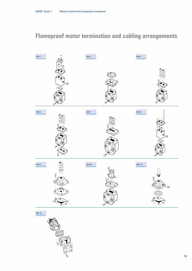
HA/1 HA/4 HA/5
HA/6 HA/7 HA/8
HA/9 HA/10 HA/12
HA/13
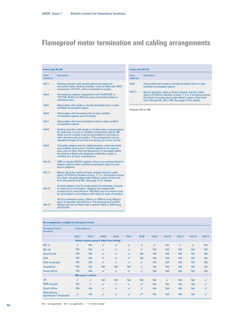
Flameproof motor termination and cabling arrangements
14
2203E Issue 1 Electric motors for hazardous locations
Frame sizes 90-180
Chartreference
HA/11
HA/4
HA/5
HA/6
HA/7
HA/81
HA/9
HA/10
HA/11
HA/12
HA/13
Sealing chamber with double gland and clamp forarmoured cable. Sealing chamber must be filled with BICCcompound, ref G101, when connected to supply.
Terminal box adaptor designed to suit ‘HUWOOD’ or‘VICTOR’ 30-50 and 200 amp plug and socket bolted orrestrained type.
Gland plate with single or double threaded entry to takecertified compression gland.
Gland plate with threaded entry to take certifiedcompression gland, up to 6 entries.
Gland plate with three threaded entries to take certifiedcompression gland.
Sealing chamber with single or double entry screwed glandfor seamless conduit or certified compression gland. NBOther end of conduit must be terminated in accordancewith relevant code of practice. This arrangement can berepeated at base of terminal box giving up to four entries.
Threaded adaptor box for cable between motor terminalsand certified remote box. Certified glands to be used ateach end of cable. Remote flameproof or increased safetyterminal box fitted with duplicate certification plate orcertified box of other manufacture.
CMP or Hawke G470/C adaptor. One or two entries direct toadaptor plate to take certified compression gland to suitabove adaptors.
Barrier gland for cable or Kopex stopper (barrier) cablegland ref HCM for flexible conduit. 1, 2 or 3 threaded entriesinto flush-mounted gland plate (fitted in place of terminalbox) (Groups IIA and IIB). See page 15 for details.
Conduit adaptor box for loose leads (via seamless conduit)to customer’s termination. Adaptor box sealed withcompound by manufacturer. NB Other end of conduit mustbe terminated in accordance with relevant code of practice.
SG Iron extension piece, 150mm or 200mm long, fitted inplace of standard terminal box. The terminal box is NCBdesign and can be fitted with a special 150A or 200A plugand socket.
Description
HA arrangements available for flameproof motors
Flameproof motorstandards
EEx d
EEx de
(Ex)d 3n G4
CSA
SAA (Australia)
Yugoslavia
South Africa
UK
EMR Canada
South Africa
NSW Miningspecification (Australia)
HA/1
✓
NA
NA
NA
NA
NA
NA
✓
NA
NA
✓
HA/4
NA
NA
NA
NA
NA
NA
NA
✓
✓
NA
OA
HA/5
✓
✓
✓
✓
✓
NA
✓
NA
✓
✓
✓
HA/6
✓
✓
✓
✓
✓
NA
✓
NA
✓
✓
✓
HA/7
✓
✓
✓
✓
✓
NA
✓
NA
✓
✓
✓
HA/8
✓
✓
NA
NA
✓
✓
✓
NA
✓
✓
✓ *
HA/9
✓
NA
NA
NA
NA
NA
NA
NA
NA
NA
NA
HA/10
NA
NA
NA
NA
NA
NA
NA
✓
NA
NA
NA
HA/11
✓
NA
NA
NA
NA
NA
NA
NA
NA
NA
NA
HA/12
✓
NA
NA
NA
NA
NA
NA
NA
NA
NA
NA
HA/13
NA
NA
NA
NA
NA
NA
NA
✓
✓
✓
✓
Chart reference
Surface industry group II (other than mining)
MEx group 1 (mines)
Frame sizes 90-315
Chartreference
HA/5
HA/11
1Frames 132 to 180
Gland plate with single or double threaded entry to takecertified compression gland.
Barrier gland for cable or Kopex stopper (barrier) cablegland ref HCM for flexible conduit. 1, 2 or 3 threaded entriesinto flush-mounted gland plate (fitted in place of terminalbox) (Groups IIA, IIB or IIB). See page 15 for details.
Description
NA = not applicable OA = on application * = not for conduit
Flameproof motor termination and cabling arrangements
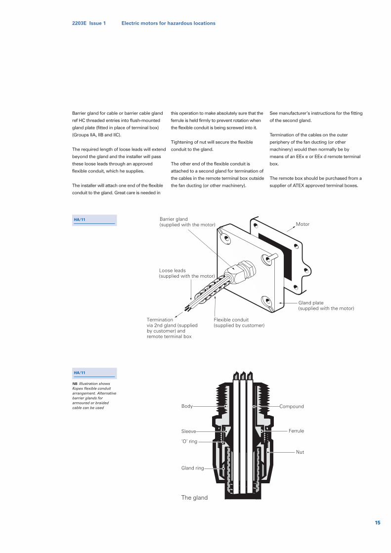
Barrier gland for cable or barrier cable gland
ref HC threaded entries into flush-mounted
gland plate (fitted in place of terminal box)
(Groups IIA, IIB and IIC).
The required length of loose leads will extend
beyond the gland and the installer will pass
these loose leads through an approved
flexible conduit, which he supplies.
The installer will attach one end of the flexible
conduit to the gland. Great care is needed in
this operation to make absolutely sure that the
ferrule is held firmly to prevent rotation when
the flexible conduit is being screwed into it.
Tightening of nut will secure the flexible
conduit to the gland.
The other end of the flexible conduit is
attached to a second gland for termination of
the cables in the remote terminal box outside
the fan ducting (or other machinery).
See manufacturer’s instructions for the fitting
of the second gland.
Termination of the cables on the outer
periphery of the fan ducting (or other
machinery) would then normally be by
means of an EEx e or EEx d remote terminal
box.
The remote box should be purchased from a
supplier of ATEX approved terminal boxes.
Barrier gland(supplied with the motor)
Loose leads(supplied with the motor)
Terminationvia 2nd gland (suppliedby customer) andremote terminal box
Flexible conduit(supplied by customer)
Gland plate(supplied with the motor)
Motor
Body
Sleeve
‘O’ ring
Gland ring
Compound
Ferrule
Nut
The gland
HA/11
HA/11
NB Illustration showsKopex flexible conduitarrangement. Alternativebarrier glands forarmoured or braidedcable can be used
2203E Issue 1 Electric motors for hazardous locations
15
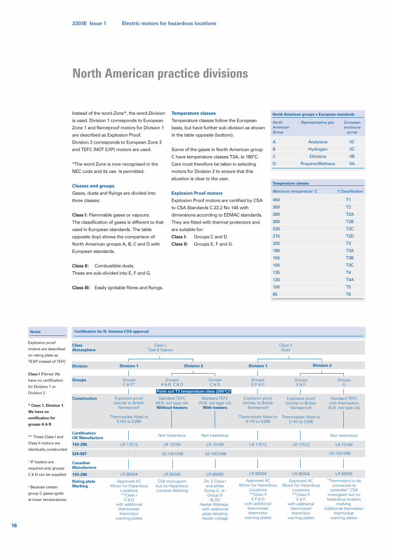
Instead of the word Zone*, the word Division
is used. Division 1 corresponds to European
Zone 1 and flameproof motors for Division 1
are described as Explosion Proof.
Division 2 corresponds to European Zone 2
and TEFC (NOT EXP) motors are used.
*The word Zone is now recognised in the
NEC code and its use is permitted.
Classes and groups
Gases, dusts and flyings are divided into
three classes:
Class I: Flammable gases or vapours.
The classification of gases is different to that
used in European standards. The table
opposite (top) shows the comparison of
North American groups A, B, C and D with
European standards.
Class II: Combustible dusts.
These are sub-divided into E, F and G.
Class III: Easily ignitable fibres and flyings.
Temperature classes
Temperature classes follow the European
basis, but have further sub-division as shown
in the table opposite (bottom).
Some of the gases in North American group
C have temperature classes T3A, ie 180°C.
Care must therefore be taken in selecting
motors for Division 2 to ensure that this
situation is clear to the user.
Explosion Proof motors
Explosion Proof motors are certified by CSA
to CSA Standards C.22.2 No 145 with
dimensions according to EEMAC standards.
They are fitted with thermal protectors and
are suitable for:
Class I: Groups C and D
Class II: Groups E, F and G.
North American groups v European standards
NorthAmericanGroup
A
B
C
D
Acetylene
Hydrogen
Ethylene
Propane/Methane
IIC
IIC
IIB
IIA
Representative gas Europeanenclosure
group
Temperature classes
Maximum temperature °C
450
300
280
260
230
215
200
180
165
160
135
120
100
85
T1
T2
T2A
T2B
T2C
T2D
T3
T3A
T3B
T3C
T4
T4A
T5
T6
T Classification
ClassAtmosphere
Division
Groups
Construction
CertificationUK Manufacture 143-286
CanadianManufacture
143-286
Rating plateMarking
Division 1
GroupsC & D*
Explosion proof(similar to British
flameproof)
Thermostats fitted toE143 to E286
LR 17512
-
LR 69304
Approved ACMotor for Hazardous
Locations**Class I
C & Dwith additional
thermostat/thermistor
warning plates
Division 2
GroupsA & B, C & D
Standard TEFC(N.B. not type nA)Without heaters
Non hazardous
LR 10159
02-1001096
LR 69305
CSA monogrambut no HazardousLocation Marking
GroupsC & D
Standard TEFC(N.B. not type nA)
With heaters
Non hazardous
LR 10159
02-1001096
LR 69305
Div 2 Class Iand either
Group C, or Group D
ALSOHeater Wattage. with additionalplate detailingheater voltage
Class I†Gas & Vapour
Division 1
GroupsE F & G
Explosion proof(similar to British
flameproof)
Thermostats fitted toE143 to E286
LR 17512
-
LR 69304
Approved ACMotor for Hazardous
Locations**Class IIE F & G
with additionalthermostat/thermistor
warning plates
Division 2
GroupsE & F
Explosion proof(similar to British
flameproof)
Thermostats fitted toE143 to E286
LR 17512
-
LR 69304
Approved ACMotor for Hazardous
Locations**Class II
E & Fwith additional
thermostat/thermistor
warning plates
GroupsG
Standard TEFCwith thermistors
(N.B. not type nA)
Non hazardous
LR 10159
02-1001096
LR 69305
“Thermistors to be connected to
controller” CSA monogram but no hazardous location
marking.Additional thermistor/
thermostatwarning plates
Class IIDust
Point out T3 temperature class (200°C)§
324-587
Certification for N. America CSA approvalNotes
Explosion proof
motors are described
on rating plate as
TEXP instead of TEFC
Class I (Fibres) We
have no certification
for Division 1 or
Division 2
* Class 1, Division 1.
We have no
certification for
groups A & B
** These Class I and
Class II motors are
identically constructed
† IF heaters are
required only groups
C & D can be supplied
§ Because certain
group C gases ignite
at lower temperatures
16
2203E Issue 1 Electric motors for hazardous locations
North American practice divisions
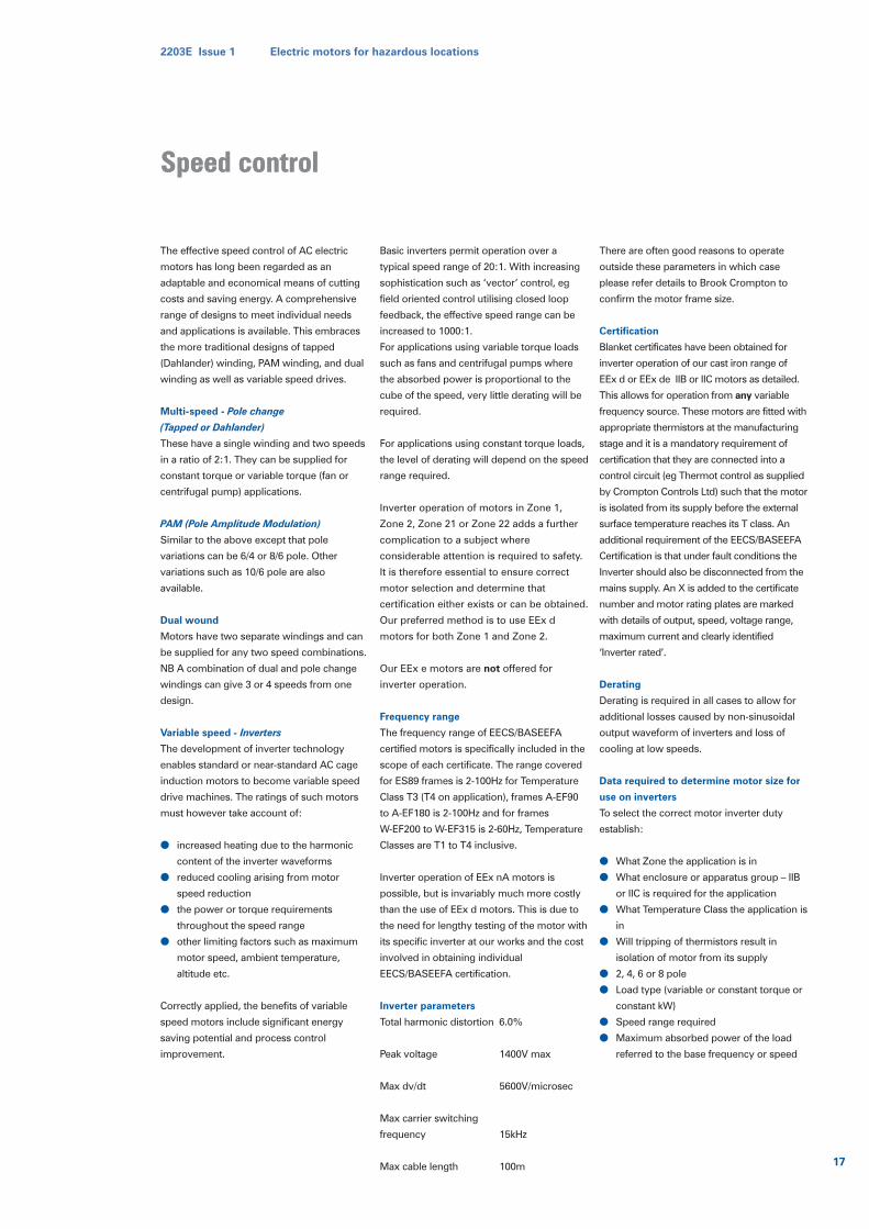
The effective speed control of AC electric
motors has long been regarded as an
adaptable and economical means of cutting
costs and saving energy. A comprehensive
range of designs to meet individual needs
and applications is available. This embraces
the more traditional designs of tapped
(Dahlander) winding, PAM winding, and dual
winding as well as variable speed drives.
Multi-speed - Pole change
(Tapped or Dahlander)
These have a single winding and two speeds
in a ratio of 2:1. They can be supplied for
constant torque or variable torque (fan or
centrifugal pump) applications.
PAM (Pole Amplitude Modulation)
Similar to the above except that pole
variations can be 6/4 or 8/6 pole. Other
variations such as 10/6 pole are also
available.
Dual wound
Motors have two separate windings and can
be supplied for any two speed combinations.
NB A combination of dual and pole change
windings can give 3 or 4 speeds from one
design.
Variable speed - Inverters
The development of inverter technology
enables standard or near-standard AC cage
induction motors to become variable speed
drive machines. The ratings of such motors
must however take account of:
● increased heating due to the harmonic
content of the inverter waveforms
● reduced cooling arising from motor
speed reduction
● the power or torque requirements
throughout the speed range
● other limiting factors such as maximum
motor speed, ambient temperature,
altitude etc.
Correctly applied, the benefits of variable
speed motors include significant energy
saving potential and process control
improvement.
Basic inverters permit operation over a
typical speed range of 20:1. With increasing
sophistication such as ‘vector’ control, eg
field oriented control utilising closed loop
feedback, the effective speed range can be
increased to 1000:1.
For applications using variable torque loads
such as fans and centrifugal pumps where
the absorbed power is proportional to the
cube of the speed, very little derating will be
required.
For applications using constant torque loads,
the level of derating will depend on the speed
range required.
Inverter operation of motors in Zone 1,
Zone 2, Zone 21 or Zone 22 adds a further
complication to a subject where
considerable attention is required to safety.
It is therefore essential to ensure correct
motor selection and determine that
certification either exists or can be obtained.
Our preferred method is to use EEx d
motors for both Zone 1 and Zone 2.
Our EEx e motors are not offered for
inverter operation.
Frequency range
The frequency range of EECS/BASEEFA
certified motors is specifically included in the
scope of each certificate. The range covered
for ES89 frames is 2-100Hz for Temperature
Class T3 (T4 on application), frames A-EF90
to A-EF180 is 2-100Hz and for frames
W-EF200 to W-EF315 is 2-60Hz, Temperature
Classes are T1 to T4 inclusive.
Inverter operation of EEx nA motors is
possible, but is invariably much more costly
than the use of EEx d motors. This is due to
the need for lengthy testing of the motor with
its specific inverter at our works and the cost
involved in obtaining individual
EECS/BASEEFA certification.
Inverter parameters
Total harmonic distortion 6.0%
Peak voltage 1400V max
Max dv/dt 5600V/microsec
Max carrier switching
frequency 15kHz
Max cable length 100m
There are often good reasons to operate
outside these parameters in which case
please refer details to Brook Crompton to
confirm the motor frame size.
Certification
Blanket certificates have been obtained for
inverter operation of our cast iron range of
EEx d or EEx de IIB or IIC motors as detailed.
This allows for operation from any variable
frequency source. These motors are fitted with
appropriate thermistors at the manufacturing
stage and it is a mandatory requirement of
certification that they are connected into a
control circuit (eg Thermot control as supplied
by Crompton Controls Ltd) such that the motor
is isolated from its supply before the external
surface temperature reaches its T class. An
additional requirement of the EECS/BASEEFA
Certification is that under fault conditions the
Inverter should also be disconnected from the
mains supply. An X is added to the certificate
number and motor rating plates are marked
with details of output, speed, voltage range,
maximum current and clearly identified
‘Inverter rated’.
Derating
Derating is required in all cases to allow for
additional losses caused by non-sinusoidal
output waveform of inverters and loss of
cooling at low speeds.
Data required to determine motor size for
use on inverters
To select the correct motor inverter duty
establish:
● What Zone the application is in
● What enclosure or apparatus group – IIB
or IIC is required for the application
● What Temperature Class the application is
in
● Will tripping of thermistors result in
isolation of motor from its supply
● 2, 4, 6 or 8 pole
● Load type (variable or constant torque or
constant kW)
● Speed range required
● Maximum absorbed power of the load
referred to the base frequency or speed
2203E Issue 1 Electric motors for hazardous locations
17
Speed controlSpeed control
Dust hazards
A surprisingly large number of dusts are
capable of being ignited by external ignition
sources and will continue to burn at
atmospheric temperatures. They will,
however, only spontaneously ignite above a
certain temperature. The list of dusts
includes natural products such as wood,
flour, cocoa, sugar, milk powder and tea, as
well as various metals and chemicals
including bronze, zinc, sulphur and toner.
The table on page 19 indicates the properties
of combustible dusts.
We have a complete range of motors to
European standard EN 50281 for electrical
equipment working in dust hazards. Cast iron
is the standard material. This standard uses
Zone 20, 21 and 22 (Motors are not supplied
for Zone 20).
These motors are not flameproof design but
are TEFV with either IP6X or IP5X protection
depending on the Zone and type of dust:
* Motors supplied by Brook Crompton are of
enclosure classification IP65 or IP55.
The specification takes account of dust
present in a cloud in normal operation and a
layer up to 5mm thick. Dust is therefore
excluded from the motor and only the external
surface temperature of the motor is exposed
to the dust cloud or layer. It is necessary for
the user to practice good housekeeping and
ensure that this layer thickness is not
exceeded. Examination at intervals not greater
than three months is required. This range of
motors has a maximum surface temperature
of 125°C in an ambient of 40°C. Thermistors
are not mandatory but are recommended in
all cases.
ATEX approval has been obtained and
certification is compliant with EN 50281
Marking of the motors will include the new
system required by ATEX which is detailed on
page 5.
The previous British standard for motors in
dust hazards was BS 6467 which used zones Z
and Y. There had also been German standard
VDE 0165 which referred to zones 10 and 11.
Both of these standards are superseded by
EN 50281.
Testing
Motor testing to determine IP category is
carried out in a dust test chamber where
French chalk/talcum powder, having a
minimum particle size of 1 micron, is blown
around the motor which is itself subjected to
a partial vacuum. Motors which are too large
for the dust chamber are designed and
manufactured in an identical manner to
those which are type tested (cf EN 60529 cl
11.2). Based on type tests, declaration of
conformity documents are issued.
Tests are carried out to ensure that motors
will withstand a specified impact as stated in
EN 50281.
Some installations may be subjected to more
than one type of hazard. The presence of
combustible dusts may occur along with
gases, vapours etc. Under these
circumstances it is possible to incorporate
certification covering both types of hazard.
The motor would carry a dual certification
rating plate.
The motor would be required to comply with
the more stringent of the two applicable
hazard protection. E.g. a EEx e motor
certified for use in a Zone 1 (category 2) T3
gas hazard and a Zone 21 (category 2) dust
hazard. This motor would need to be IP6X
enclosure protected, with an external surface
temperature of 125°C, whilst its internal
surfaces would be required to comply with
the temperature limits of T3 (200°C).
The dual certification gas/vapour and dust
concept can be applied to all ranges of
hazardous areas motors as detailed below.
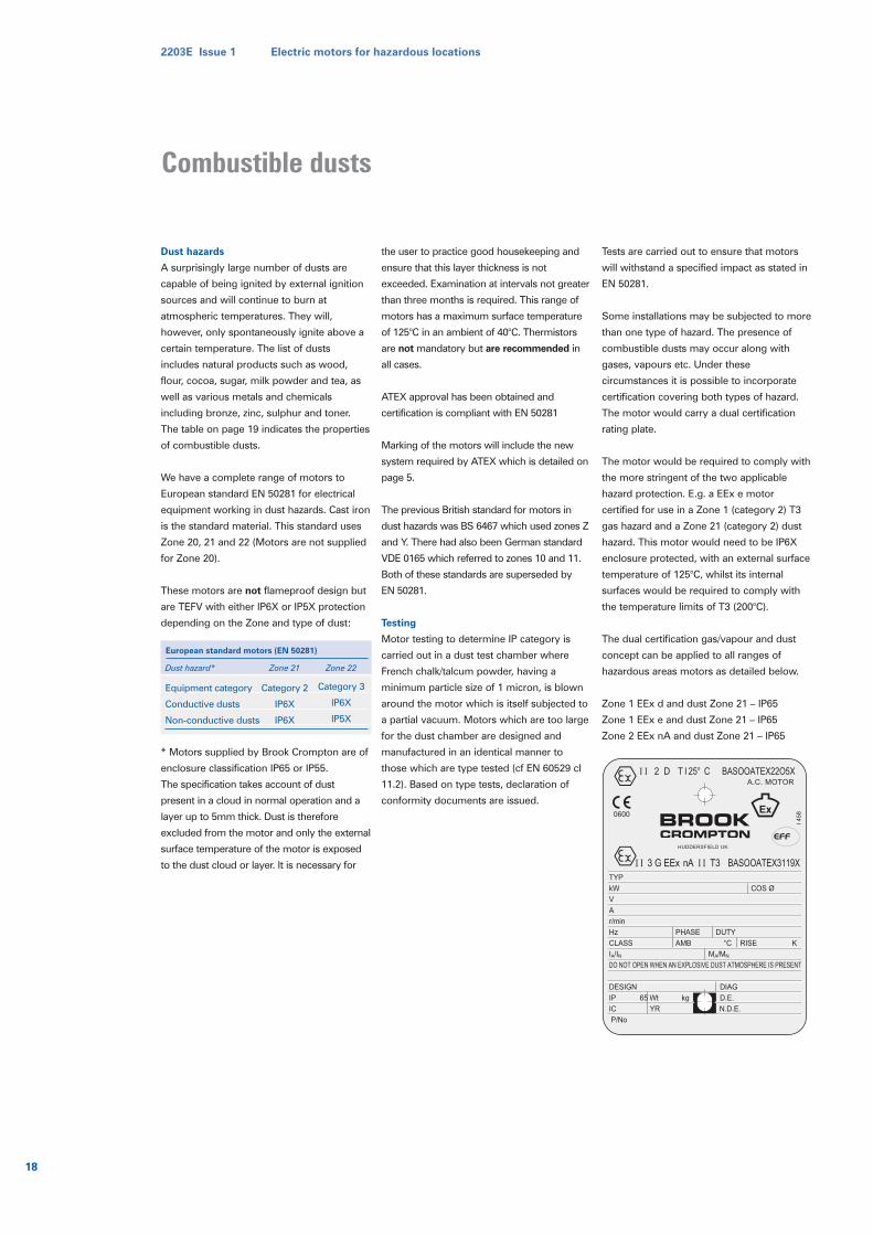
Zone 1 EEx d and dust Zone 21 – IP65
Zone 1 EEx e and dust Zone 21 – IP65
Zone 2 EEx nA and dust Zone 21 – IP65
Dust hazard*
Equipment category
Conductive dusts
Non-conductive dusts
Category 2
IP6X
IP6X
Category 3
IP6X
IP5X
Zone 21 Zone 22
European standard motors (EN 50281)
TYP
kW COS Ø
V
A
r/min
Hz PHASE DUTY
CLASS AMB °C RISE K
IA/IN MA/MN
DO NOT OPEN WHEN AN EXPLOSIVE DUST ATMOSPHERE IS PRESENT
DESIGN DIAG
IP 65 Wt kg D.E.
IC YR N.D.E.
P/No
I 4
580600
I I 3 G EEx nA I I T3 BASOOATEX3119X
HUDDERSFIELD UK
I I 2 D T I 25° C BASOOATEX22O5XA.C. MOTOR
18
2203E Issue 1 Electric motors for hazardous locations
Combustible dusts
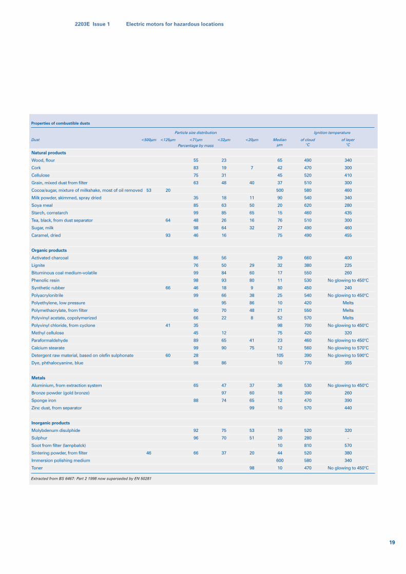
Properties of combustible dusts
Dust <500µm <125µm <71µm
Particle size distribution
Percentage by mass
Ignition temperature
<32µm <20µm Medianµm
of cloud°C
of layer°C
Natural products
Wood, flour
Cork
Cellulose
Grain, mixed dust from filter
Cocoa/sugar, mixture of milkshake, most of oil removed
Milk powder, skimmed, spray dried
Soya meal
Starch, cornstarch
Tea, black, from dust separator
Sugar, milk
Caramel, dried
Organic products
Activated charcoal
Lignite
Bituminous coal medium-volatile
Phenolic resin
Synthetic rubber
Polyacrylonitrile
Polyethylene, low pressure
Polymethacrylate, from filter
Polyvinyl acetate, copolymerized
Polyvinyl chloride, from cyclone
Methyl cellulose
Paraformaldehyde
Calcium stearate
Detergent raw material, based on olefin sulphonate
Dye, phthalocyanine, blue
Metals
Aluminium, from extraction system
Bronze powder (gold bronze)
Sponge iron
Zinc dust, from separator
Inorganic products
Molybdenum disulphide
Sulphur
Soot from filter (lampbalck)
Sintering powder, from filter
Immersion polishing medium
Toner
53
46
20
64
93
66
41
60
55
83
75
63
35
85
99
48
98
46
86
76
99
98
46
99
90
66
35
45
89
99
28
98
65
88
92
96
66
65
42
45
37
500
90
20
15
76
27
75
29
32
17
11
80
25
10
21
52
98
75
23
12
105
10
36
18
12
10
19
20
10
44
600
10
7
40
11
50
65
16
32
29
60
80
9
38
86
48
8
41
75
37
60
65
99
53
51
20
98
23
19
31
48
18
63
85
26
64
16
56
50
84
93
18
66
95
70
22
12
65
90
86
47
97
74
75
70
37
490
470
520
510
580
540
620
460
510
490
490
660
380
550
530
450
540
420
550
570
700
420
460
560
390
770
530
390
470
570
520
280
810
520
580
470
340
300
410
300
460
340
280
435
300
460
455
400
225
260
No glowing to 450°C
240
No glowing to 450°C
Melts
Melts
Melts
No glowing to 450°C
320
No glowing to 450°C
No glowing to 570°C
No glowing to 590°C
355
No glowing to 450°C
260
390
440
320
-
570
380
340
No glowing to 450°C
Extracted from BS 6467: Part 2 1998 now superseded by EN 50281
2203E Issue 1 Electric motors for hazardous locations
19
Paint treatments
All Brook Crompton hazardous area motors
are completed with a standard paint finish,
which can be used in total confidence in
many hostile environments.
However, there are certain industrial
applications, which demand a stronger,
more superior paint system to deal with
more rigorous environments. Alternative
paint finishes, which all incorporate the
brand name ‘Argus’, are Argus Super Seal,
Argus Super Chem and Argus Monsoon.
Standard specification
All hazardous area motors are finished with
a standard paint treatment, which is suitable
for most industrial environments.
All motors have the following features as
standard:-
The paint treatment specification is as
follows:
● primer - frames, endshields and terminal
boxes/lids are dipped or sprayed with
anticorrosive primer with a minimum
DFT (dry film thickness) of 15 microns
● top coat - completed motors are
sprayed with a final coat with a
minimum DFT thickness of 50 microns
in colour RAL 5021 (Water Blue)
Finished motors will have a minimum DFT
of 70 microns.
Argus Super Seal
Argus Super Seal is the ideal finish where
‘wash down’ conditions are required such
as the food and pharmaceutical industries,
and general wet temperature conditions
such as quarries etc.
The motors are designed to meet the
guidelines of the German VIK (Verband der
Industriellen Energie – und Kraftwirtschaft
e.V.), and many other major user
specifications.
In addition to the paint treatment, each
motor has internal tropic proof treatment
and enclosure protection to IP56 (higher
degrees of protection available on request).
The paint treatment specification is as
follows:
● primer - frames, endshields and terminal
boxes/lids are dipped or sprayed with
anticorrosive primer with a minimum
DFT (dry film thickness) of 15 microns
● top coat - completed motors are
sprayedwith a final coat with a minimum
DFT thickness of 50 microns in colour
RAL 5021 (Water Blue)
Finished motors will have a minimum DFT
of 70 microns.
Argus Super Chem
Argus Super Chem offers a treatment
suitable for operation in such arduous
conditions such as chemical and
petrochemical plants, pulp, salt laden,
dockside duty, sewage works and cooling
towers.
In addition to the paint treatment, each
motor has internal tropic proof treatment,
metal cooling fan for IC411 cooling,
thermistor protection and enclosure
protection to IP56 (higher degrees of
protection are available on request).
The three part paint treatment specification
is as follows:
● completed motors are grit blast to SA 2.5
microns
● primer – 50 microns epoxy zinc rich
● intermediate – minimum 125 microns
high build epoxy
● top coat – minimum 50 microns high
build epoxy
Finished motors will have a minimum DFT
of 225 microns.
Tropical protection
Standard motors will operate satisfactorily
in tropical environments.
Where ambient conditions are conducive to
the formation of fungal growth, algae or
condensation, an extra tropic proof
treatment is recommended as additional
protection. The use of drain holes to assist
in the draining of any condensation is also
recommended.
Where the motor is to be left standing for
long periods of time in damp conditions or
subject to condensation forming
atmospheres, it is recommended that anti-
condensation heaters are fitted and
energised to prevent condensation forming
in the motor enclosure. Motor controls
should be provided to activate the heaters,
only when the motor is de-energised.
The heater cables are terminated to a
separate terminal block inside the motor
terminal box normally with a single phase
supply to the heaters of 220-240 volts. 110
volt heaters available on request.
Argus Monsoon Tropical Treatment
Motors operating in tropical climates are
invariably subjected to the hot, humid and
wet conditions which produce considerable
amounts of condensation on internal
surfaces.
In these areas, fluctuating temperatures can
vary between 25-40°C (76-105°F), with
relative humidity often reaching 100%.
Intermittent periods of tropical rainfall are
also part of the natural environment.
Condensation occurs when the surface
temperature of the motor is lower than the
dew-point temperature of the ambient air
and, if motors do not have special internal
protec-tion, resulting corrosion can cause
irreparable damage to stator windings and
moving parts. In such conditions, motors
are most at risk from deterioration when
not in use – particularly when stored in
humid or un-ventilated areas.
For motors operating in such arduous
conditions, Brook Crompton has developed
Argus Monsoon Tropical Treatment – an
enhanced form of protection which ensures
that both internal and external surfaces are
free from corrosive attack. This same
treatment is also suitable for motors
subjected to frequent deluge and heat/
thermal cycling, as is often experienced in
the petrochemical, paper, glass-making and
textile industries.
20
2203E Issue 1 Electric motors for hazardous locations
Paint treatments
During manufacture, the surfaces of ex-
ternal components are grit blasted to
Swedish standard SA 2.5 and various parts
of the motor’s enclosure, including stator
frame, endshields, bearing caps and
terminal box, are coated with etch primer.
All internal components of the motor are
treated with a specially developed tropic
proof varnish, which is carefully applied to
ensure complete coverage to all surfaces.
Machined surfaces, which are particularly
vulnerable, are treated with a rust inhibitive
primer and a proprietary non-setting liquid
gasket material.
Following the standard impregnation of
stator windings with electrical varnish, the
complete stator assembly, including
winding overhangs, wound pack end faces
and stator bore, are treated with tropic
proof varnish.
As standard, all motors are supplied with
tapped holes in drive-end shafts, to
facilitate assembly, securing and removal of
fitments. Internal and external earth
terminals are provided to ensure maximum
safety and bearings with C3 diametrical
clearances are fitted to ensure long life and
optimum reliability in service.
Every motor has a stainless steel name
plate for ease of identification, even after
lengthy periods of operation in hostile and
corrosive atmospheres.
All Argus Monsoon Tropical Treatment
motors are covered by a 2-year guarantee.
External paint system
All treatments are well in excess of re-
quirements for exterior, exposed, polluted
and coastal atmospheres for medium term
(5-10 years), as specified in BS5493* 1977
Section 2, Part 3.
Treatment is as follows:
● Grit blast SA 2.5
● 50 microns J984 Epoxy zinc rich primer
coat
● 250 microns L653 High build epoxy
intermediate coat
● 50 microns M137 overcoatable
polyurethane finish coat
Total thickness: DFT 350 microns
The final high quality paint system meets
the standard required for offshore use by all
leading oil company operators.
* BS5493: Code of Practice for protective
coating of iron and steel structures against
corrosion.
Testing
To ensure that Brook Crompton Argus
Monsoon Tropical Treatment motors fully
comply with various international
requirements (defined under IEC 68-2-28:
1990 Environment Testing, Part 2.2
Guidance, Tests C and D Guidance for
damp heat tests) a number of samples were
exposed to independent accelerated testing
procedures at the UK laboratories of a
leading international testing organisation –
ERA Technology, Leatherhead, Surrey,
England.
Under controlled conditions, carried out in
an environmental test chamber, motors
were subjected to temperatures between
25°C and 65°C and much greater levels of
condensation than would normally be
experienced in actual tropical climates.
Rigorous tests were also carried out to
accelerate the rate at which changes in the
condition of the motor would occur in
practice, but without radically changing the
degradation mechanisms. Acceleration of
these test conditions was achieved by
increasing the maximum rapid changes in
temperature; maintaining high humidity and
increasing the number of environmental
cycles per day. The capability of the stator
winding insulation to withstand these same
conditions was carefully monitored.
Tests were designed to increase and
decrease temperature by 20°C per hour, ie
twelve times the rate of change for
category B2 – Wet Hot, experienced under
the most extreme tropical conditions
described in UK defence standard Def Stan
00-1/2.
The extent of any degradation was
determined by measuring the winding
insulation resistance during the test and by
post-test inspection of all internal and
external surfaces of the motor.
Test results, received from ERA, in its
Report 94-0421, proved the exceptional
quality, not only of the motor’s external
paint system – which remained totally free
from corrosion – but also of the special
treatment given to all internal surfaces.
The quality and effectiveness of the
treatment given to the stator windings
ensured that insulation resistance, at the
end of the test period, was at least an order
of magnitude greater than the minimum
values which could normally be expected
from a new motor working at 25°C.
Applications
A substantial number of Brook Crompton
Argus Monsoon motors are currently
operating in extreme climatic conditions in
a number of Middle and Far Eastern
countries, providing cost-effective solutions
to drive applications in a wide range of
chemical and process industries.
Fumex motors
Fan-powered ventilation systems –
designed to remove heat and smoke during
‘fire emergency’ situations – are being
increasingly installed as potential life-savers
in all kinds of commercial and industrial
buildings. Some of these systems serve the
dual purpose of providing effective air
ventilation under normal conditions and
smoke/heat extraction duty in the event of
a fire, whilst others are installed specifically
as ‘fire emergency’ safety systems.
Fumex EEx d, EEx nA, EEx e or dust
ignition proof motors are suitable for
installation on most types of extraction fan,
including both axial flow and bifurcated
systems.
It must be noted that during the emergency
duty, the zone and temperature
classification will be exceeded, therefore by
implications the certification becomes
invalidated.
2203E Issue 1 Electric motors for hazardous locations
21
Paint treatments/Fumex
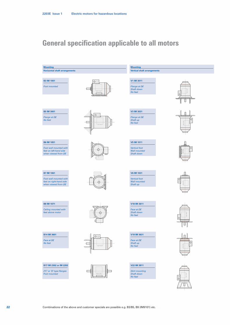
B3 IM 1001
Foot mounted
B5 IM 3001
Flange at DENo feet
B6 IM 1051
Foot wall mounted withfeet on left-hand sidewhen viewed from DE
B7 IM 1061
Foot wall mounted withfeet on right-hand sidewhen viewed from DE
B8 IM 1071
Ceiling mounted withfeet above motor
B14 IM 3601
Face at DENo feet
B17 IM 2302 or IM 2202
2‘C’ or ‘D’ type flangesFoot mounted
Mounting
Horizontal shaft arrangements
V1 IM 3011
Flange at DE Shaft downNo feet
V3 IM 3031
Flange at DEShaft upNo feet
V5 IM 1011
Vertical footWall mountedShaft down
V6 IM 1031
Vertical footWall mountedShaft up
V18 IM 3611
Face at DEShaft downNo feet
V19 IM 3631
Face at DEShaft upNo feet
V22 IM 3811
Skirt mountingShaft downNo feet
Mounting
Vertical shaft arrangements
Combinations of the above and customer specials are possible e.g. B3/B5, B9 (IM9101) etc.22
2203E Issue 1 Electric motors for hazardous locations
General specification applicable to all motors
2203E Issue 1 Electric motors for hazardous locations
23
Cooling arrangements
Code
IC411
IC410
IC418
Totally Enclosed Fan Ventilated (TEFV)
motor cooled by an externally mounted fan
Totally Enclosed Non Ventilated (TENV)
self cooling, no externally mounted fan
Totally Enclosed Air Over Motor (TEAOM)
motor cooled by the airstream
Arrangement
Derating for high ambient temperature
Ambient temperature
Class B temperature limits
Class F temperature limits
45°C
96%
100%
50°C
93%
100%
55°C
87%
100%
Derating for altitude
Altitude
Class B temperature limits
Class F temperature limits
2000m
94%
100%
3000m
85%
100%
4000m
75%
95%
Timetable relativity to European & British voltage changes
Pre 1995
1.1.95
2003
Pre 1995
1.1.95
2003
Date Location Voltage (V) Comments
Mainland Europe
Mainland Europe
Mainland Europe
UK
UK
UK
380 ± 5%
400 +6/-10%
400 ± 10%
415 + 6%
400 + 10/-6%
400 ± 10%
–
–
–
–
No real change to
supply voltage range
–
Enclosure description
Brief description1st numeral
Protection against solid objects
Protection against the harmful ingress of dust
Dust tight. No ingress of dust
N/A
N/A
2nd numeralProtection against liquids
5
6
7
8
Motor enclosure protected against the harmful ingress of water, whenwater is sprayed against the motor enclosure (12.5L/min @ 0.3 bar)
Motor enclosure protected against the harmful ingress of water, whenwater jets or heavy seas are directed against the motor enclosure
(100L/min @ 1.0 bar)
Protected against the effect of immersion for a minimum of 30 minutes,with the lowest part of the motor at depth of 1 metre
†Protected against the effects of submersion for a minimumof 24 hours at a depth of 7 metres
5
6
7
8
†- not specified in EN 60034
Enclosure
All motors are totally enclosed with a
minimum ingress protection of IP55. Higher
IP protection can be supplied as detailed in
the table above.
Motor cooling
Motors are cooled in accordance with
IEC 60034-6. The normal arrangement is
IC411 (Totally Enclosed Fan Ventilated) via a
fan mounted at the non-drive end. Methods
of cooling are detailed in the table opposite.
Insulation and thermal rating
Standard motors will operate satisfactorily
in an ambient temperature range of –20°C to
+40°C (Class B temperature rise) and at
altitudes up to 1000 metres above sea level.
The use of a UL approved class F insulation
system with only Class B temperature rise
(80°C) ensures an exceptional margin of
safety and longer life even in abnormal
operating conditions.
Class F insulation system material includes
‘Nomex’ meta-aramid paper and ‘Mylar’
polyester film (Nomex and Mylar are
registered trademarks of Du Pont.)
High ambient temperatures and high
altitudes
Ratings listed in associate catalogues apply
to standard motors operating in ambient
temperatures not exceeding 40°C and
altitudes up to 1000m above sea level.
When operating EEx d/de, EEx nA or dust
ignition proof motors, in higher ambient
temperatures or at higher altitudes, derating
may be necessary in order to maintain its
operating temperature (Class B or Class F).
The factors detailed in the tables opposite,
should be used for derating.
For EEx e motors, please refer full application
details to Brook Crompton.
The actual performance figures, of a derated
standard motor, will differ from those
published. The larger the derating, the
further the motor performance will be from
the optimum.
In many circumstances (and for all EEx e) it
is recommended that a motor is wound for
the specific derated output. When the above
factors are used, the actual performance
figures will differ from those published.
Please refer to Brook Crompton.
Duty cycle
All Ex motors are suitable for SI Duty as
described in IEC 60034-1. For duties other
than SI, EEx d motors should be specified.
Electrical characteristics
Voltage
Ex motors are manufactured to the
requirements of IEC 60034-1. In January 1995
the first steps to a harmonised ‘Eurovoltage’
of 400V ±10%, target date 2003, were taken.
The current situation is detailed in Table 23.
All ‘W’ motors are wound for the
‘Eurovoltage’. Motors up to and including
3kW are normally supplied 230/400V, 4kW
and above supplied 400V and are suitable
for ±10% tolerance in line with the post
2003 Voltage Harmonisation requirements.
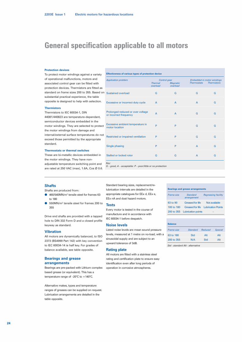
Protection devices
To protect motor windings against a variety
of operational malfunctions, motors and
associated control gear can be fitted with
protection devices. Thermistors are fitted as
standard on frame sizes 200 to 355. Based on
substantial practical experience, the table
opposite is designed to help with selection.
Thermistors
Thermistors to IEC 60034-1, DIN
44081/440823 are temperature-dependant,
semiconductor devices embedded in the
motor windings. They are selected to protect
the motor windings from damage and
internal/external surface temperatures do not
exceed those permitted by the appropriate
standard.
Thermostats or thermal switches
These are bi-metallic devices embedded in
the motor windings. They have non-
adjustable temperature switching point and
are rated at 250 VAC (max), 1.6A, Cos Ø 0.6.
ShaftsShafts are produced from:
● 460/540MN/m2 tensile steel for frames 63
to 180
● 550MN/m2 tensile steel for frames 200 to
355
Drive end shafts are provided with a tapped
hole to DIN 332 Form D and a closed profile
keyway as standard.
VibrationAll motors are dynamically balanced, to ISO
2373 (BS4999 Part 142) with key convention
to IEC 60034-14 ie half key. For grades of
balance available, see table opposite.
Bearings and greasearrangementsBearings are pre-packed with Lithium complex
based grease (or equivalent). This has a
temperature range of –20°C to +140°C.
Alternative makes, types and temperature
ranges of greases can be supplied on request.
Lubrication arrangements are detailed in the
table opposite.
Standard bearing sizes, replacement/re-
lubrication intervals are detailed in the
appropriate catalogues for EEx d, EEx e,
EEx nA and dust hazard motors.
TestsEvery motor is tested in the course of
manufacture and in accordance with
IEC 60034-1 before despatch.
Noise levelsListed noise levels are mean sound pressure
levels, measured at 1 metre on no-load, with a
sinusoidal supply and are subject to an
upward tolerance of 3dB.
Rating plateAll motors are fitted with a stainless steel
rating and certification plate to ensure easy
identification even after long periods of
operation in corrosive atmospheres.
Effectiveness of various types of protection device
Application problem
Sustained overload
Excessive or incorrect duty cycle
Prolonged reduced or over voltageor incorrect frequency
Excessive ambient temperature in motor location
Restricted or impaired ventilation
Single phasing
Stalled or locked rotor
G
A
A
P
P
P
G
G
A
A
P
P
P
G
G
A
G
G
G
A
A
G
G
G
G
G
G
G
Control gearThermal Magneticoverload overload
Embedded in motor windingsThermostats Thermistors
Key:G – good, A – acceptable: P – poor/little or no protection
Balance
Frame size
63 to 180
200 to 355
Std
N/A
Alt
Std
Alt
Alt
Standard Reduced Special
Std - standard Alt - alternative
Bearings and grease arrangements
Frame size
63 to 90
100 to 180
200 to 355
Greased for life
Greased for life
Lubrication points
Standardarrangement
Not available
Lubrication Points
–
Regreasing facility
24
2203E Issue 1 Electric motors for hazardous locations
General specification applicable to all motors
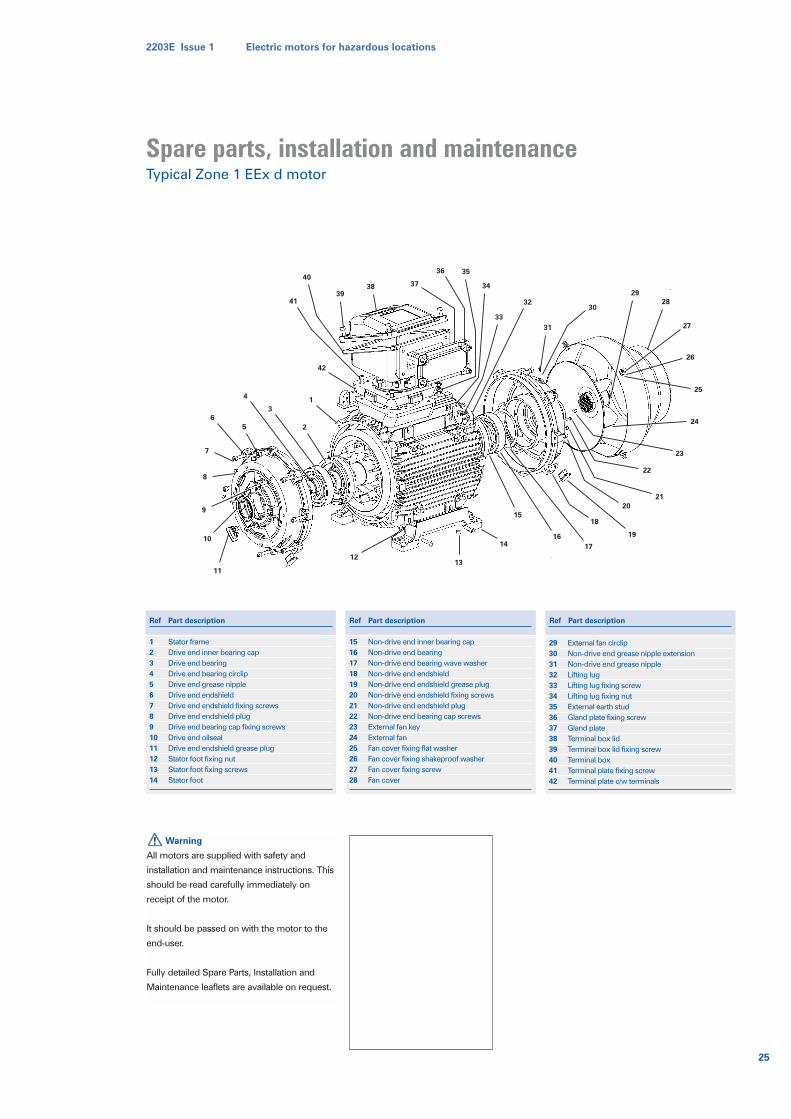
2203E Issue 1 Electric motors for hazardous locations
25
Warning
All motors are supplied with safety and
installation and maintenance instructions. This
should be read carefully immediately on
receipt of the motor.
It should be passed on with the motor to the
end-user.
Fully detailed Spare Parts, Installation and
Maintenance leaflets are available on request.
1234567891011121314
Stator frameDrive end inner bearing capDrive end bearingDrive end bearing circlipDrive end grease nippleDrive end endshieldDrive end endshield fixing screwsDrive end endshield plugDrive end bearing cap fixing screwsDrive end oilsealDrive end endshield grease plugStator foot fixing nutStator foot fixing screwsStator foot
1516171819202122232425262728
Non-drive end inner bearing capNon-drive end bearingNon-drive end bearing wave washerNon-drive end endshieldNon-drive end endshield grease plugNon-drive end endshield fixing screwsNon-drive end endshield plugNon-drive end bearing cap screws External fan keyExternal fanFan cover fixing flat washerFan cover fixing shakeproof washerFan cover fixing screwFan cover
2930313233343536373839404142
External fan circlipNon-drive end grease nipple extensionNon-drive end grease nippleLifting lugLifting lug fixing screwLifting lug fixing nutExternal earth studGland plate fixing screwGland plateTerminal box lidTerminal box lid fixing screwTerminal boxTerminal plate fixing screwTerminal plate c/w terminals
1
42
41
40
3938 37
36 35
34
33
32
31
30
29
28
2
3
4
5
6
7
8
9
10
11
27
26
25
24
23
22
21
20
19
18
17
16
15
14
1312
Ref Part description Ref Part description Ref Part description
Spare parts, installation and maintenanceTypical Zone 1 EEx d motor
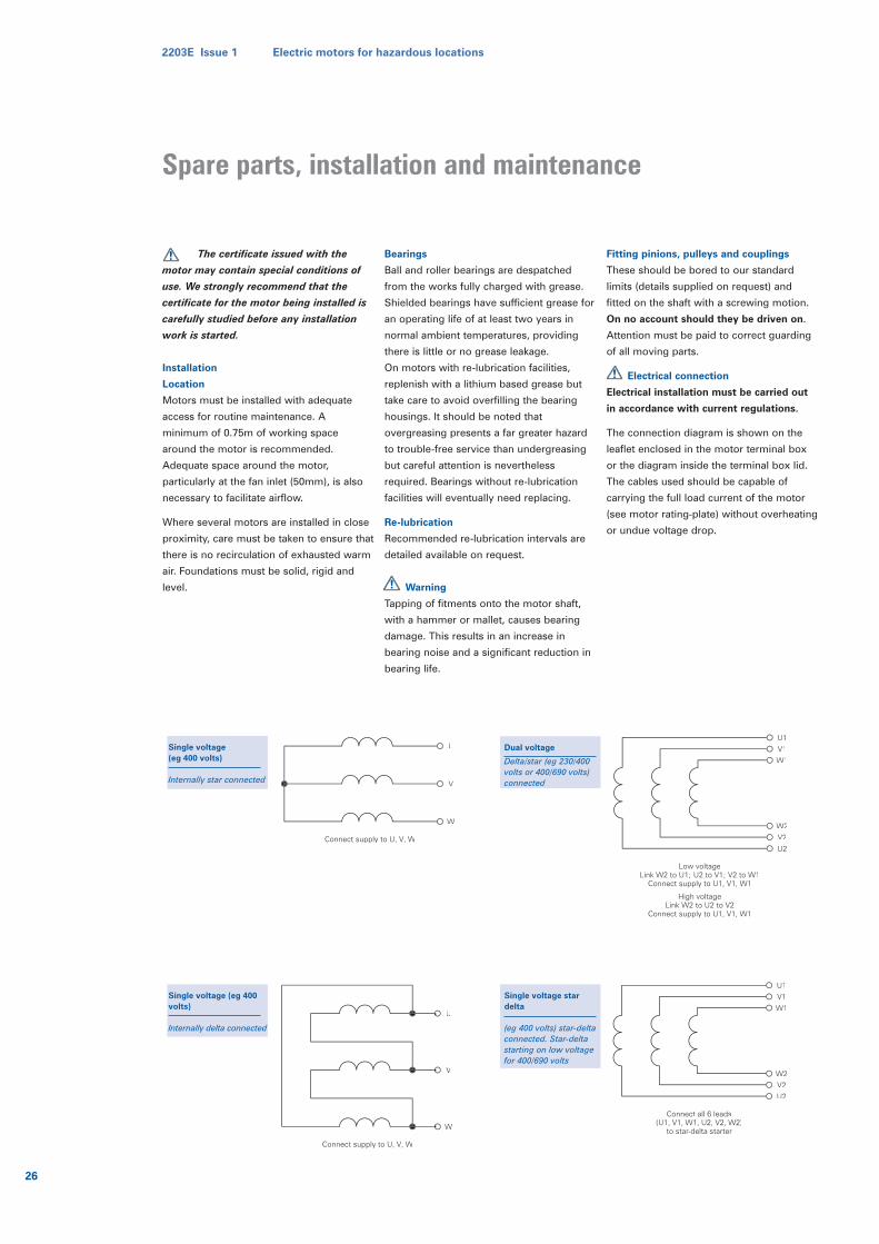
The certificate issued with the
motor may contain special conditions of
use. We strongly recommend that the
certificate for the motor being installed is
carefully studied before any installation
work is started.
Installation
Location
Motors must be installed with adequate
access for routine maintenance. A
minimum of 0.75m of working space
around the motor is recommended.
Adequate space around the motor,
particularly at the fan inlet (50mm), is also
necessary to facilitate airflow.
Where several motors are installed in close
proximity, care must be taken to ensure that
there is no recirculation of exhausted warm
air. Foundations must be solid, rigid and
level.
Bearings
Ball and roller bearings are despatched
from the works fully charged with grease.
Shielded bearings have sufficient grease for
an operating life of at least two years in
normal ambient temperatures, providing
there is little or no grease leakage.
On motors with re-lubrication facilities,
replenish with a lithium based grease but
take care to avoid overfilling the bearing
housings. It should be noted that
overgreasing presents a far greater hazard
to trouble-free service than undergreasing
but careful attention is nevertheless
required. Bearings without re-lubrication
facilities will eventually need replacing.
Re-lubrication
Recommended re-lubrication intervals are
detailed available on request.
Warning
Tapping of fitments onto the motor shaft,
with a hammer or mallet, causes bearing
damage. This results in an increase in
bearing noise and a significant reduction in
bearing life.
Fitting pinions, pulleys and couplings
These should be bored to our standard
limits (details supplied on request) and
fitted on the shaft with a screwing motion.
On no account should they be driven on.
Attention must be paid to correct guarding
of all moving parts.
Electrical connection
Electrical installation must be carried out
in accordance with current regulations.
The connection diagram is shown on the
leaflet enclosed in the motor terminal box
or the diagram inside the terminal box lid.
The cables used should be capable of
carrying the full load current of the motor
(see motor rating-plate) without overheating
or undue voltage drop.
U
V
W
Connect supply to U, V, W
Low voltageLink W2 to U1; U2 to V1; V2 to W1
Connect supply to U1, V1, W1
High voltageLink W2 to U2 to V2
Connect supply to U1, V1, W1
W1
V1
U1
U2
V2
W2
Dual voltage
Delta/star (eg 230/400volts or 400/690 volts)connected
Single voltage (eg 400volts)
Internally delta connected
Single voltage (eg 400 volts)
Internally star connected
U
V
W
Connect supply to U, V, W
Connect all 6 leads(U1, V1, W1, U2, V2, W2)
to star-delta starter
W1
V1
U1
U2
V2
W2
Single voltage stardelta
(eg 400 volts) star-deltaconnected. Star-deltastarting on low voltagefor 400/690 volts
26
2203E Issue 1 Electric motors for hazardous locations
Spare parts, installation and maintenance
The enacting of the Health and Safety at
Work Act focused attention on the
responsibility of all parties, manufacturers,
users and repairers on the repair of certified
atmosphere equipment.
In 1978 the first authoritative publication, the
‘BEAMA/AEMT Code of Practice for the
Repair and Overhaul of Electrical Apparatus’
for Use in Potentially Explosive Atmospheres
was issued. The drafting committee,
comprised of leading representatives from
the principal UK manufacturers, repairers
and users. This code has now been accepted
as sound authoritative practice and
introduced with little change by
the International Electrotechnical
Commission in 1993 as Standard
IEC 60079-19
To date the adoption of these Codes of
Practice are in no way mandatory nor is
there any direct legal requirement therefore
to comply with them, but they could
conceivably be called up as a reference work
to good established practice in any litigation
process. As a measure of their standing, the
IEC standard No 79-19 has received
recognition by the Health and Safety
Executive who called it up as repair practice
in their licensing scheme. The careful study
of these documents is therefore essential to
all engaged in the management of repair and
overhaul of this class of equipment.
Brook Crompton introduced an intensive
training course on the repair of this class of
machine in 1978. Over 1000 attendees have
participated in the course from over 250
repair and user establishments.
The Brook Crompton training course is
structured to meet the training requirements
for repairers detailed in Section 4 of the
BEAMA/AEMT Code, and also gives
specialist knowledge of our hazardous area
products and procedures, including
recognition and use of authorised spares. To
further emphasise the importance of using
correct spares and their fitting by trained
repairers, the sample label is attached to all
spares for use on hazardous area motors.
The course also applies the engineering
principles of the BEAMA/AEMT (and IEC)
Code of Practice, however some practices
are a reconciliation of divergent views and
are contrary to our recommendations for
repair. We do not therefore give specific
training for ‘Repair to the standard’, we
strongly recommend that repairs should be
carried out to the original certification using
authorised replacement parts where
necessary.
Course participants will receive a detailed
manual and on satisfactory completion of the
course, attendees are presented with a
Certificate of Training. This in conjunction
with the repair workshop facility meeting our
required standard assessed by inspection,
gives the repairer accredited status for the
repair and overhaul of Brook Crompton
motors.
Full details of the Brook Crompton repair
course can be obtained from the marketing
department at Brook Crompton or visit our
website at www.brookcrompton.com
Repair workshops
As detailed in the repair of Ex certified
motors, the repair and maintenance of Brook
Crompton hazardous area motors should
only be undertaken by repair establishments
equipped to handle these types of motor.
Brook Crompton has a large number of
world-wide approved repair establishments
to undertake the maintenance and repair of
Brook Crompton hazardous area motors.
Details of particular agents are available from
Brook Crompton.
Videos
Brook Crompton has produced a set of three
training videos covering the theory, design
and construction and repair of electric
motors for use in hazardous areas, available
from the marketing department at Brook
Crompton or visit our website at
www.brookcrompton.com
Spares for our above motor ranges are quoted/supplied on the understanding that the subsequent validity or certification of any repair* work and/or fitting of spares or replacement parts, rests with the user or repair establishment.
The repair establishment must be one where either:A. Personnel have attended our Hazardous Atmosphere Motor Repair course AND the repair establishment is considered suitably equipped for this class of work, and accredited by Brook Crompton.B. Personnel have attended the AEMT course ‘Repair and Overhaul of Ex Electrical Apparatus’ AND are in possession of our Hazardous Atmosphere Repair Manual.OR
C. The repairer meets the requirements of the BEAMA/AEMT Code or IEC60079-19 and has an
approved quality assurance system, e.g. ISO 9002
Where a motor has been originally repaired as indicated bysymbols , or in accordance with code or IEC60079-19*,details of the repair shall be obtained from the user beforeproceeding with repair.
*See AEMT/BEAMA Publication 300, Code of Practice For Repairand Overhaul of Ex Electrical Apparatus, or IEC79-19.
Training VideosA set of three videos covering the theory, design and
construction, repair of electric motors for use in hazardous areas is available from the above address.
Flameproof FLP, EEx d, EEx de, Ex d, MEx, FLPIncreased Safety EEx e, Ex e
Non-Sparking Ex N, Ex nA, EEx nADust Ignition Proof
Brook Crompton
St Thomas’ Road Huddersfield HD1 3LJ England
Tel: +44 (0)1484 557200
Fax: +44 (0)1484 530940
2203E Issue 1 Electric motors for hazardous locations
27
Repair of Ex certified motors
Brook CromptonSt Thomas’ Road HuddersfieldWest Yorkshire HD1 3LJ UKTel: +44 (0) 1484 557200Fax: +44 (0) 1484 557201E-mail: [email protected]: www.brookcrompton.com
Printed in Englandnjh065/LF/E/05/02 2203E issue 1
© Copyright 2002. Brook Crompton. All rights reserved.
R o t a t i n g E l e c t r i c a l M a c h i n e s
Every care has been taken to ensure the accuracy of the information
contained in this publication, but, due to a policy of continuous
development and improvement the right is reserved to supply products
which may differ slightly from those illustrated and described in this
publication