Embed Size (px)
Citation preview
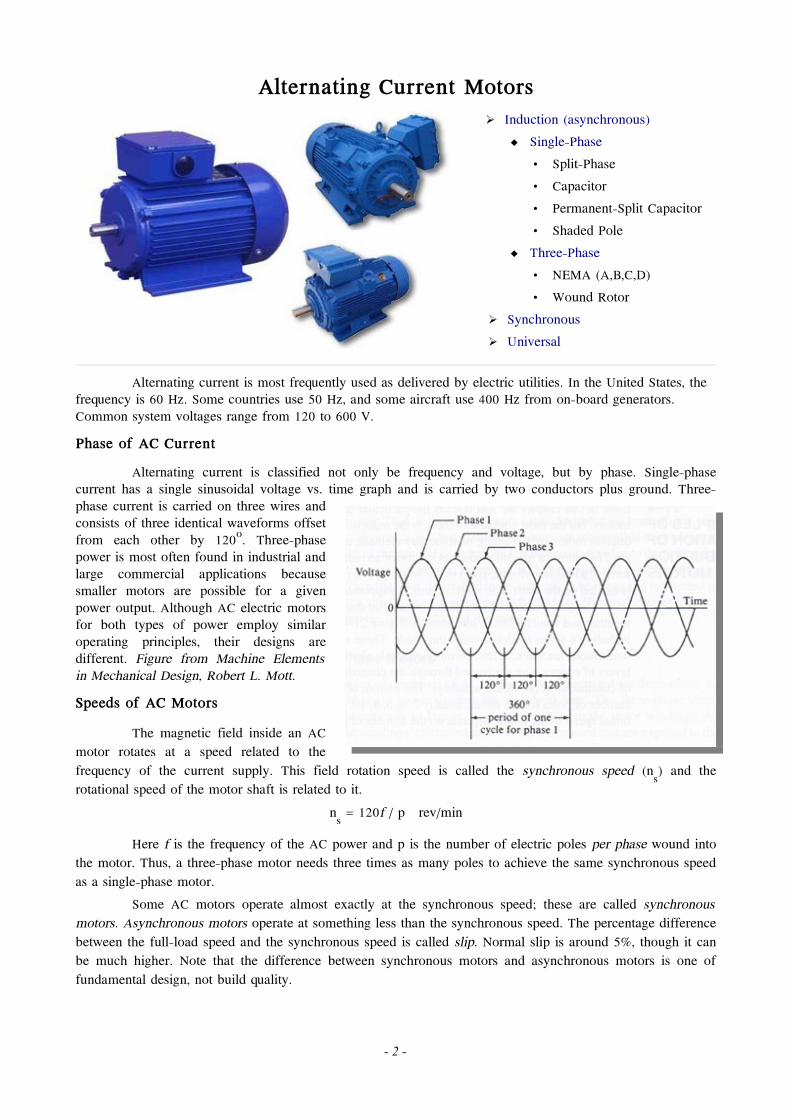
Electric Motors
Electric motors are ubiquitous in our industrial world. They are used to provide motive power for industrial machinery, consumer products and business equipment. This document will describe various types of electric motors, their design characteristics and specifications. Some detail will be given about construction, but emphasis is placed on selection of existing motors to meet the needs of a particular design.
Motor Selection CriteriaFrom Machine Elements in Mechanical Design, Robert L. Mott.
Electric motors come in a wide variety of sizes and types. Selection of an appropriate motor requires a minimum number of items as follows:
• Motor type: DC, AC, single-phase, three-phase and so on • Power rating and speed • Operating voltage and frequency • Type of enclosure • Frame size • Mounting details
A more detailed analysis would probably include the following:
• Operating torque requirements. Note these are related to speed and power by the equation Power = torque x speed.
• Starting torque requirements (often a design limitation) • Load variations and allowable speed variations • Current supply limitations • Duty cycle: how frequently the motor is started and stopped • Environmental factors: temperature, corrosive or explosive atmospheres, exposure to weather or liquids
and so on. • Voltage variations expected: Most motors can tolerate a voltage variation up to 10%. Any more
requires a special design. • Shaft loadings, especially side and thrust loads which can affect the life of shaft bearings.
Motor Size
Power output allows a rough classification of motors of similar type. These are rated in horsepower or watts (1 hp = 746 W).
• Subfractional horsepower: 0.001 to 0.040 hp (0.75 to 30W) • Fractional horsepower: 0.05 to 1.0 hp (37 to 746 W) • Integral horsepower: 1 hp (746 W) and larger
- 1 -
Alternating Current Motors
➢ Induction (asynchronous) Single-Phase • Split-Phase • Capacitor • Permanent-Split Capacitor • Shaded Pole
Three-Phase • NEMA (A,B,C,D) • Wound Rotor
➢ Synchronous ➢ Universal
Alternating current is most frequently used as delivered by electric utilities. In the United States, the frequency is 60 Hz. Some countries use 50 Hz, and some aircraft use 400 Hz from on-board generators. Common system voltages range from 120 to 600 V. Phase of AC Current
Alternating current is classified not only be frequency and voltage, but by phase. Single-phase current has a single sinusoidal voltage vs. time graph and is carried by two conductors plus ground. Three-phase current is carried on three wires and consists of three identical waveforms offset from each other by 120o. Three-phase power is most often found in industrial and large commercial applications because smaller motors are possible for a given power output. Although AC electric motors for both types of power employ similar operating principles, their designs are different. Figure from Machine Elements in Mechanical Design, Robert L. Mott. Speeds of AC Motors
The magnetic field inside an AC motor rotates at a speed related to the frequency of the current supply. This field rotation speed is called the synchronous speed (ns) and the rotational speed of the motor shaft is related to it.
ns = 120f / p rev/min
Here f is the frequency of the AC power and p is the number of electric poles per phase wound into the motor. Thus, a three-phase motor needs three times as many poles to achieve the same synchronous speed as a single-phase motor.
Some AC motors operate almost exactly at the synchronous speed; these are called synchronous motors. Asynchronous motors operate at something less than the synchronous speed. The percentage difference between the full-load speed and the synchronous speed is called slip. Normal slip is around 5%, though it can be much higher. Note that the difference between synchronous motors and asynchronous motors is one of fundamental design, not build quality.
- 2 -
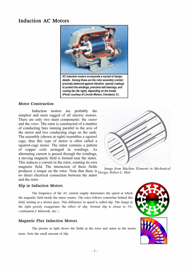
Induction AC Motors
Motor ConstructionInduction motors are probably the
simplest and most rugged of all electric motors. There are only two main components: the stator and the rotor. The rotor is constructed of a number of conducting bars running parallel to the axis of the motor and two conducting rings on the ends. The assembly (shown at right) resembles a squirrel cage, thus this type of motor is often called a squirrel-cage motor. The stator contains a pattern of copper coils arranged in windings. As alternating current is passed through the windings, a moving magnetic field is formed near the stator. This induces a current in the rotor, creating its own magnetic field. The interaction of these fields produces a torque on the rotor. Note that there is no direct electrical connection between the stator and the rotor.
Image from Machine Elements in Mechanical Design, Robert L. Mott
Slip in Induction MotorsThe frequency of the AC current supply determines the speed at which
the magnetic field inside the stator rotates. The rotor follows somewhat behind this field, turning at a slower pace. This difference in speed is called slip. The image at the right grossly exaggerates the effect of slip. Normal slip is closer to 5%. (Animation © Motorola, Inc. )
Magnetic Flux Induction MotorsThe picture at right shows the fields in the rotor and stator as the motor
turns. Note the small amount of slip.
- 3 -
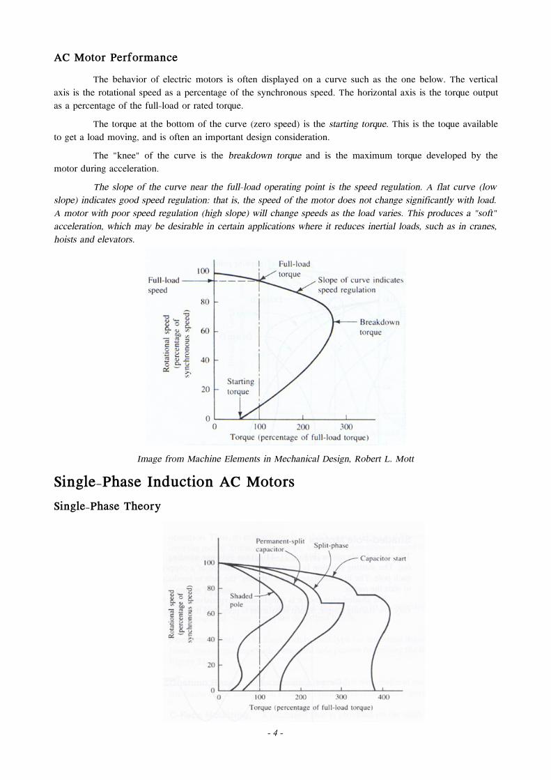
AC Motor PerformanceThe behavior of electric motors is often displayed on a curve such as the one below. The vertical
axis is the rotational speed as a percentage of the synchronous speed. The horizontal axis is the torque output as a percentage of the full-load or rated torque.
The torque at the bottom of the curve (zero speed) is the starting torque. This is the toque available to get a load moving, and is often an important design consideration.
The "knee" of the curve is the breakdown torque and is the maximum torque developed by the motor during acceleration.
The slope of the curve near the full-load operating point is the speed regulation. A flat curve (low slope) indicates good speed regulation: that is, the speed of the motor does not change significantly with load. A motor with poor speed regulation (high slope) will change speeds as the load varies. This produces a "soft" acceleration, which may be desirable in certain applications where it reduces inertial loads, such as in cranes, hoists and elevators.
Image from Machine Elements in Mechanical Design, Robert L. Mott
Single-Phase Induction AC MotorsSingle-Phase Theory
- 4 -
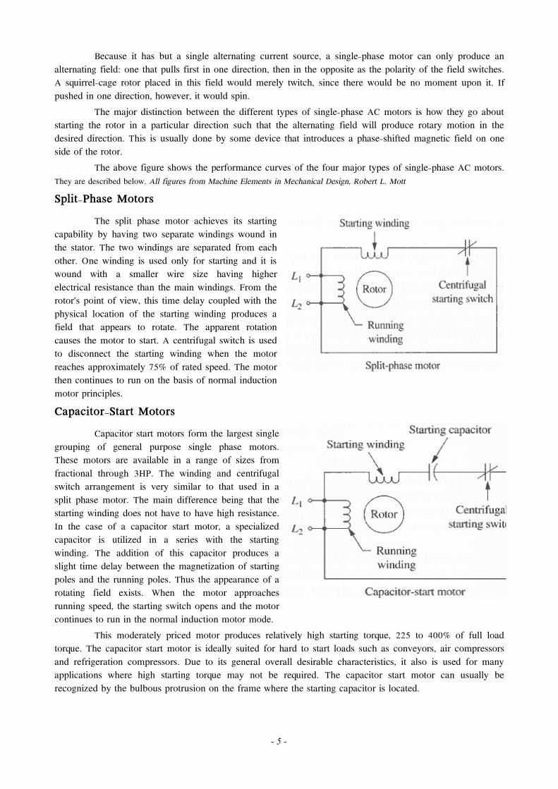
Because it has but a single alternating current source, a single-phase motor can only produce an alternating field: one that pulls first in one direction, then in the opposite as the polarity of the field switches. A squirrel-cage rotor placed in this field would merely twitch, since there would be no moment upon it. If pushed in one direction, however, it would spin.
The major distinction between the different types of single-phase AC motors is how they go about starting the rotor in a particular direction such that the alternating field will produce rotary motion in the desired direction. This is usually done by some device that introduces a phase-shifted magnetic field on one side of the rotor.
The above figure shows the performance curves of the four major types of single-phase AC motors. They are described below. All figures from Machine Elements in Mechanical Design, Robert L. Mott
Split-Phase MotorsThe split phase motor achieves its starting
capability by having two separate windings wound in the stator. The two windings are separated from each other. One winding is used only for starting and it is wound with a smaller wire size having higher electrical resistance than the main windings. From the rotor's point of view, this time delay coupled with the physical location of the starting winding produces a field that appears to rotate. The apparent rotation causes the motor to start. A centrifugal switch is used to disconnect the starting winding when the motor reaches approximately 75% of rated speed. The motor then continues to run on the basis of normal induction motor principles. Capacitor-Start Motors
Capacitor start motors form the largest single grouping of general purpose single phase motors. These motors are available in a range of sizes from fractional through 3HP. The winding and centrifugal switch arrangement is very similar to that used in a split phase motor. The main difference being that the starting winding does not have to have high resistance. In the case of a capacitor start motor, a specialized capacitor is utilized in a series with the starting winding. The addition of this capacitor produces a slight time delay between the magnetization of starting poles and the running poles. Thus the appearance of a rotating field exists. When the motor approaches running speed, the starting switch opens and the motor continues to run in the normal induction motor mode.
This moderately priced motor produces relatively high starting torque, 225 to 400% of full load torque. The capacitor start motor is ideally suited for hard to start loads such as conveyors, air compressors and refrigeration compressors. Due to its general overall desirable characteristics, it also is used for many applications where high starting torque may not be required. The capacitor start motor can usually be recognized by the bulbous protrusion on the frame where the starting capacitor is located.
- 5 -
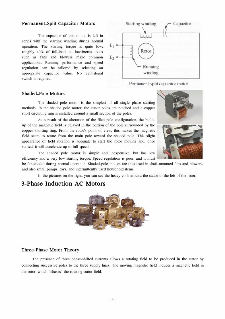
Permanent-Split Capacitor Motors
The capacitor of this motor is left in series with the starting winding during normal operation. The starting torque is quite low, roughly 40% of full-load, so low-inertia loads such as fans and blowers make common applications. Running performance and speed regulation can be tailored by selecting an appropriate capacitor value. No centrifugal switch is required.
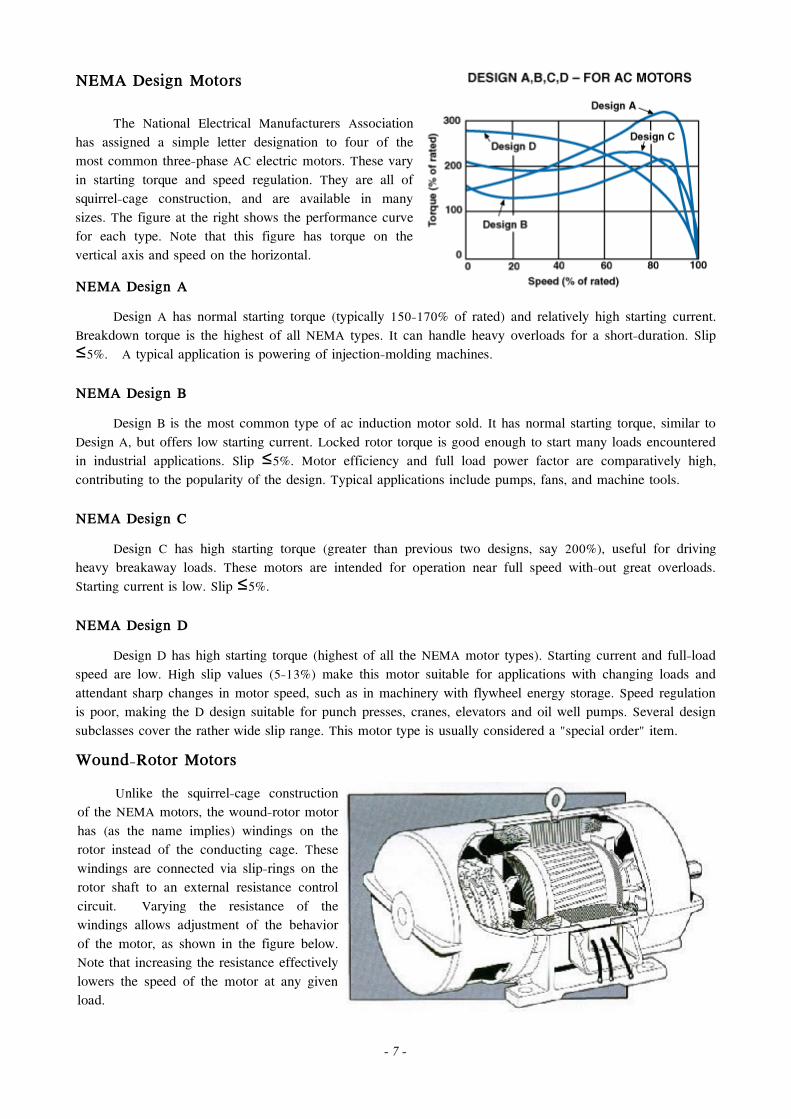
Shaded-Pole MotorsThe shaded pole motor is the simplest of all single phase starting
methods. In the shaded pole motor, the stator poles are notched and a copper short circuiting ring is installed around a small section of the poles.
As a result of the alteration of the filed pole configuration, the build-up of the magnetic field is delayed in the portion of the pole surrounded by the copper shorting ring. From the rotor's point of view, this makes the magnetic field seem to rotate from the main pole toward the shaded pole. This slight appearance of field rotation is adequate to start the rotor moving and, once started, it will accelerate up to full speed.
The shaded pole motor is simple and inexpensive, but has low efficiency and a very low starting torque. Speed regulation is poor, and it must be fan-cooled during normal operation. Shaded-pole motors are thus used in shaft-mounted fans and blowers, and also small pumps, toys, and intermittently used household items.
In the pictures on the right, you can see the heavy coils around the stator to the left of the rotor.
3-Phase Induction AC Motors
Three-Phase Motor Theory
The presence of three phase-shifted currents allows a rotating field to be produced in the stator by connecting successive poles to the three supply lines. The moving magnetic field induces a magnetic field in the rotor, which "chases" the rotating stator field.
- 6 -
NEMA Design Motors
The National Electrical Manufacturers Association has assigned a simple letter designation to four of the most common three-phase AC electric motors. These vary in starting torque and speed regulation. They are all of squirrel-cage construction, and are available in many sizes. The figure at the right shows the performance curve for each type. Note that this figure has torque on the vertical axis and speed on the horizontal.
NEMA Design ADesign A has normal starting torque (typically 150-170% of rated) and relatively high starting current.
Breakdown torque is the highest of all NEMA types. It can handle heavy overloads for a short-duration. Slip 5%. A typical application is powering of injection-molding machines. ≤
NEMA Design BDesign B is the most common type of ac induction motor sold. It has normal starting torque, similar to
Design A, but offers low starting current. Locked rotor torque is good enough to start many loads encountered in industrial applications. Slip 5%. Motor efficiency and full load power factor are comparatively high,≤ contributing to the popularity of the design. Typical applications include pumps, fans, and machine tools.
NEMA Design CDesign C has high starting torque (greater than previous two designs, say 200%), useful for driving
heavy breakaway loads. These motors are intended for operation near full speed with-out great overloads. Starting current is low. Slip 5%. ≤
NEMA Design DDesign D has high starting torque (highest of all the NEMA motor types). Starting current and full-load
speed are low. High slip values (5-13%) make this motor suitable for applications with changing loads and attendant sharp changes in motor speed, such as in machinery with flywheel energy storage. Speed regulation is poor, making the D design suitable for punch presses, cranes, elevators and oil well pumps. Several design subclasses cover the rather wide slip range. This motor type is usually considered a "special order" item.
Wound-Rotor MotorsUnlike the squirrel-cage construction
of the NEMA motors, the wound-rotor motor has (as the name implies) windings on the rotor instead of the conducting cage. These windings are connected via slip-rings on the rotor shaft to an external resistance control circuit. Varying the resistance of the windings allows adjustment of the behavior of the motor, as shown in the figure below. Note that increasing the resistance effectively lowers the speed of the motor at any given load.
- 7 -
Figure from Machine Elements in Mechanical Design, Robert L. Mott
VFD Speed ControlsWhen operating at anything other
than maximum speed, the resistance control of a wound-rotor motor consumes power that would otherwise be used to move the load. This inherent inefficiency of the wound-rotor design has lead to its obsolescence. Applications requiring variable-speed three-phase motors now use a variable frequency drive (VFD) to adjust the speed of a standard squirrel-cage motor. The VFD electronically changes the frequency of the AC current supply, thus changing the synchronous speed of the motor. This has considerable benefits in power consumption over the resistance control.
Synchronous AC Motors
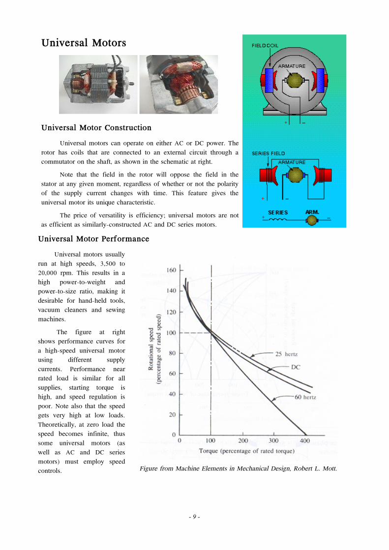
The synchronous motor, as its name implies, operates at exactly synchronous
speed with no slip. The rotor is of a constant polarity (either a permanent magnet or an energized electromagnet) and the windings of the stator are wrapped in such a way as to produce a rotating magnetic field. Such motors provide very little torque at zero speed, and thus need some kind of separate starting apparatus. Often a squirrel-cage rotor is built into the main rotor. When the motor reaches a few percent of synchronous speed, the rotor is energized and the squirrel cage becomes ineffective.
A synchronous motor will run at speed regardless of load variations up to a point called the pull-out torque. A load higher than this will pull the motor out of synchronism and cause it to stop.
- 8 -
Universal Motors
Universal Motor ConstructionUniversal motors can operate on either AC or DC power. The
rotor has coils that are connected to an external circuit through a commutator on the shaft, as shown in the schematic at right.
Note that the field in the rotor will oppose the field in the stator at any given moment, regardless of whether or not the polarity of the supply current changes with time. This feature gives the universal motor its unique characteristic.
The price of versatility is efficiency; universal motors are not as efficient as similarly-constructed AC and DC series motors.
Universal Motor Performance Universal motors usually run at high speeds, 3,500 to 20,000 rpm. This results in a high power-to-weight and power-to-size ratio, making it desirable for hand-held tools, vacuum cleaners and sewing machines.
The figure at right shows performance curves for a high-speed universal motor using different supply currents. Performance near rated load is similar for all supplies, starting torque is high, and speed regulation is poor. Note also that the speed gets very high at low loads. Theoretically, at zero load the speed becomes infinite, thus some universal motors (as well as AC and DC series motors) must employ speed controls. Figure from Machine Elements in Mechanical Design, Robert L. Mott.
- 9 -
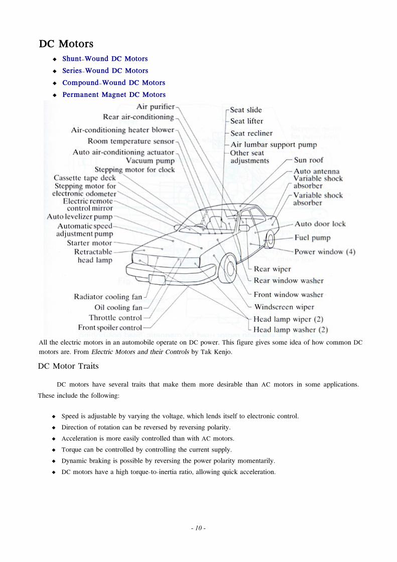
DC Motors Shunt-Wound DC Motors Series-Wound DC Motors Compound-Wound DC Motors Permanent Magnet DC Motors
All the electric motors in an automobile operate on DC power. This figure gives some idea of how common DC motors are. From Electric Motors and their Controls by Tak Kenjo.
DC Motor TraitsDC motors have several traits that make them more desirable than AC motors in some applications.
These include the following:
Speed is adjustable by varying the voltage, which lends itself to electronic control. Direction of rotation can be reversed by reversing polarity. Acceleration is more easily controlled than with AC motors. Torque can be controlled by controlling the current supply. Dynamic braking is possible by reversing the power polarity momentarily. DC motors have a high torque-to-inertia ratio, allowing quick acceleration.
- 10 -
Wound-Rotor DC MotorsOne variety of DC motor has windings on the rotor which are energized
via a commutator on the shaft and brushes. The stator is constant-polarity, either a permanent magnet or energized electromagnet. Types include shunt-wound, series-wound, compound-wound and permanent magnet DC motors, all described on following pages. In each case, wear and possible maintenance of the brushes is a significant design issue. As well, the sparking of the brushes on the commutator can be a safety hazard. Animation © Motorola; Inc.
Brushless DC MotorsTo give DC motors the reliability of AC induction motors, brushless motors
were developed. These use an electronic control to sequentially energize the stator poles. A permanent magnet rotor then follows the field. Because large permanent magnets are unweildy, brushless DC motors are usually small.
Brushless motors provide less maintenance, longer life, lower electromagnetic interference and quieter operation than wound rotor DC motors, though at a higher cost, primarily because of the control electronics involved. They produce more output power per frame size than wound DC motors. Their linear speed/torque characteristics produce predictable speed regulation. Brush inspection is eliminated making them ideal for limited access areas and applications where servicing is difficult. Low voltage models are ideal for battery operation, portable equipment, or medical applications where shock hazards cannot be tolerated. A common application is cooling fans for electronic devices. Animation © Motorola; Inc.
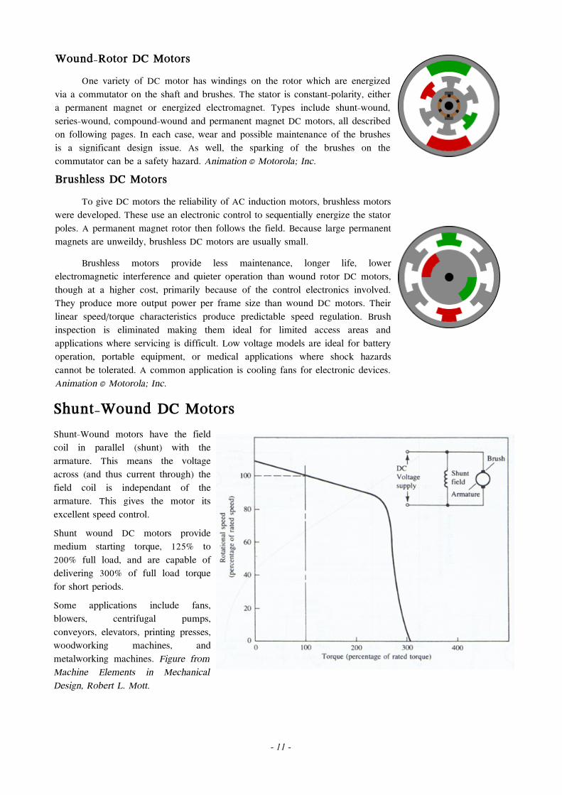
Shunt-Wound DC MotorsShunt-Wound motors have the field coil in parallel (shunt) with the armature. This means the voltage across (and thus current through) the field coil is independant of the armature. This gives the motor its excellent speed control. Shunt wound DC motors provide medium starting torque, 125% to 200% full load, and are capable of delivering 300% of full load torque for short periods. Some applications include fans, blowers, centrifugal pumps, conveyors, elevators, printing presses, woodworking machines, and metalworking machines. Figure from Machine Elements in Mechanical Design, Robert L. Mott.
- 11 -
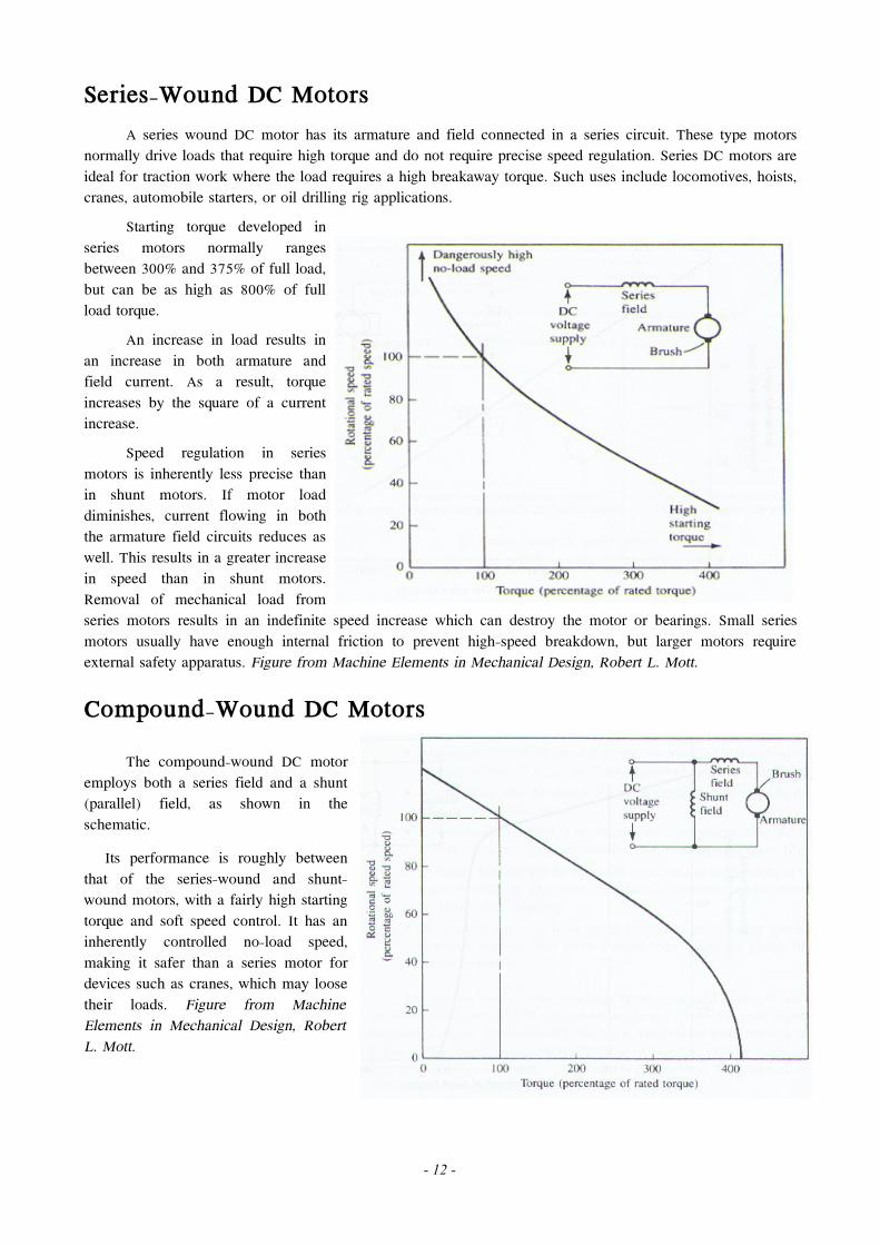
Series-Wound DC MotorsA series wound DC motor has its armature and field connected in a series circuit. These type motors
normally drive loads that require high torque and do not require precise speed regulation. Series DC motors are ideal for traction work where the load requires a high breakaway torque. Such uses include locomotives, hoists, cranes, automobile starters, or oil drilling rig applications.
Starting torque developed in series motors normally ranges between 300% and 375% of full load, but can be as high as 800% of full load torque.
An increase in load results in an increase in both armature and field current. As a result, torque increases by the square of a current increase.
Speed regulation in series motors is inherently less precise than in shunt motors. If motor load diminishes, current flowing in both the armature field circuits reduces as well. This results in a greater increase in speed than in shunt motors. Removal of mechanical load from series motors results in an indefinite speed increase which can destroy the motor or bearings. Small series motors usually have enough internal friction to prevent high-speed breakdown, but larger motors require external safety apparatus. Figure from Machine Elements in Mechanical Design, Robert L. Mott.
Compound-Wound DC MotorsThe compound-wound DC motor
employs both a series field and a shunt (parallel) field, as shown in the schematic.
Its performance is roughly between that of the series-wound and shunt-wound motors, with a fairly high starting torque and soft speed control. It has an inherently controlled no-load speed, making it safer than a series motor for devices such as cranes, which may loose their loads. Figure from Machine Elements in Mechanical Design, Robert L. Mott.
- 12 -
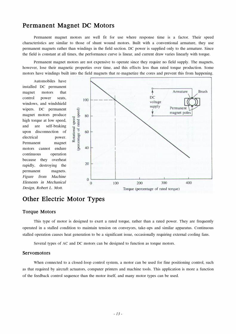
Permanent Magnet DC MotorsPermanent magnet motors are well fit for use where response time is a factor. Their speed
characteristics are similar to those of shunt wound motors. Built with a conventional armature, they use permanent magnets rather than windings in the field section. DC power is supplied only to the armature. Since the field is constant at all times, the performance curve is linear, and current draw varies linearly with torque.
Permanent magnet motors are not expensive to operate since they require no field supply. The magnets, however, lose their magnetic properties over time, and this effects less than rated torque production. Some motors have windings built into the field magnets that re-magnetize the cores and prevent this from happening.
Automobiles have installed DC permanent magnet motors that control power seats, windows, and windshield wipers. DC permanent magnet motors produce high torque at low speed, and are self-braking upon disconnection of electrical power. Permanent magnet motors cannot endure continuous operation because they overheat rapidly, destroying the permanent magnets. Figure from Machine Elements in Mechanical Design, Robert L. Mott.
Other Electric Motor TypesTorque Motors
This type of motor is designed to exert a rated torque, rather than a rated power. They are frequently operated in a stalled condition to maintain tension on conveyors, take-ups and similar apparatus. Continuous stalled operation causes heat generation to be a significant issue, occasionally requiring external cooling fans.
Several types of AC and DC motors can be designed to function as torque motors.
ServomotorsWhen connected to a closed-loop control system, a motor can be used for fine positioning control, such
as that required by aircraft actuators, computer printers and machine tools. This application is more a function of the feedback control sequence than the motor itself, and many motor types can be used.
- 13 -
Stepper Motors
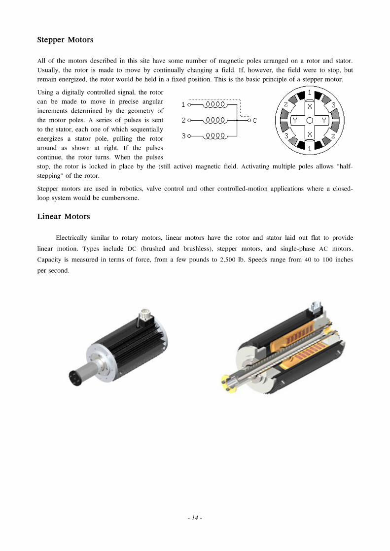
All of the motors described in this site have some number of magnetic poles arranged on a rotor and stator. Usually, the rotor is made to move by continually changing a field. If, however, the field were to stop, but remain energized, the rotor would be held in a fixed position. This is the basic principle of a stepper motor. Using a digitally controlled signal, the rotor can be made to move in precise angular increments determined by the geometry of the motor poles. A series of pulses is sent to the stator, each one of which sequentially energizes a stator pole, pulling the rotor around as shown at right. If the pulses continue, the rotor turns. When the pulses stop, the rotor is locked in place by the (still active) magnetic field. Activating multiple poles allows "half-stepping" of the rotor. Stepper motors are used in robotics, valve control and other controlled-motion applications where a closed-loop system would be cumbersome.
Linear Motors
Electrically similar to rotary motors, linear motors have the rotor and stator laid out flat to provide linear motion. Types include DC (brushed and brushless), stepper motors, and single-phase AC motors. Capacity is measured in terms of force, from a few pounds to 2,500 lb. Speeds range from 40 to 100 inches per second.
- 14 -