Embed Size (px)
Citation preview
UL 499
ISBN 0-7629-0161-6
Electric Heating Appliances

July 17, 1998 – UL 499 tr1
Underwriters Laboratories Inc. (UL)333 Pfingsten RoadNorthbrook, IL 60062-2096
UL Standard for Safety forElectric Heating Appliances, UL 499
Twelfth Edition, Dated March 26, 1997
Revisions: This Standard contains revisions through and including July 17, 1998. UL is in the process ofconverting its Standards for Safety to the Standard Generalized Markup Language (SGML). SGML -- aninternational standard (ISO 8879-1986) -- is a descriptive markup language that describes a document'sstructure and purpose, rather than its physical appearance on the page. Significant benefits that will result fromUL's use of SGML are increased productivity, reduced turnaround times, and data and information consistency,reusability, shareability, and portability. The changes noted in these revised pages are needed to modify theformat and layout of this Standard to allow it to be converted to SGML. These editorial changes are now ineffect.
A change is indicated by a note following the affected item. The note is preceded and followed by an asterisk.
The revised requirements are substantially in accordance with UL's Bulletin on this subject dated November11, 1997. The bulletin is now obsolete and may be discarded.
The revisions dated July 17, 1998 include a reprinted title page (page 1) for this Standard.
As indicated on the title page (page 1), this UL Standard for Safety has been adopted by the Department ofDefense.
The master for this Standard at UL's Northbrook Office is the official document insofar as it relates to a ULservice and the compliance of a product with respect to the requirements for that product and service, or if thereare questions regarding the accuracy of this Standard.
UL's Standards for Safety are copyrighted by UL. Neither a printed copy of a Standard, nor the distributiondiskette for a Standard-on-Diskette and the file for the Standard on the distribution diskette should be alteredin any way. All of UL's Standards and all copyrights, ownerships, and rights regarding those Standards shallremain the sole and exclusive property of UL.
All rights reserved. No part of this publication may be reproduced, stored in a retrieval system, or transmittedin any form by any means, electronic, mechanical photocopying, recording, or otherwise without priorpermission of UL.
Revisions of UL Standards for Safety are issued from time to time. A UL Standard for Safety is current only ifit incorporates the most recently adopted revisions.
UL provides this Standard "as is" without warranty of any kind, either expressed or implied, including but notlimited to, the implied warranties of merchantability or fitness for any purpose.
In no event will UL be liable for any special, incidental, consequential, indirect or similar damages, includingloss of profits, lost savings, loss of data, or any other damages arising out of the use of or the inability to usethis Standard, even if UL or an authorized UL representative has been advised of the possibility of such
damage. In no event shall UL's liability for any damage ever exceed the price paid for this Standard, regardlessof the form of the claim.

tr3 July 17, 1998 – UL 499
UL will attempt to answer support requests concerning WordPerfect, Envoy, and Standards-on-Diskette.However, this support service is offered on a reasonable efforts basis only, and UL may not be able to resolveevery support request. UL supports a Standards-on-Diskette only if it is used under the conditions and operatingsystems for which it is intended. UL’s support polices may change from time-to-time without notification.
UL reserves the right to change the format, presentation, file types and formats, delivery methods and formats,and the like of both its printed and electronic Standards without prior notice.
Standards-on-Diskette purchasers agree to defend, indemnify, and hold UL harmless from and against anyloss, expense, liability, damage, claim, or judgement (including reasonable attorney's fees) resulting from anyerror or deviation introduced while purchaser is storing a Standard-on-Diskette on the purchaser's computersystem.
If a single-user version Standards-on-Diskette was purchased, one copy of this Standard may be stored on thehard disk of a single personal computer, or on a single LAN file-server or the permanent storage device of amultiple-user computer in such a manner that this Standard may only be accessed by one user at a time andfor which there is no possibility of multiple concurrent access. The original distribution diskette should be storedin a safe place.
If a multiple-user version Standards-on-Diskette was purchased, one copy of the Standard may be stored ona single LAN file-server, or on the permanent storage device of a multiple-user computer. The number ofconcurrent users shall not exceed the number of users authorized for the Standards-on-Diskette version. Theoriginal distribution diskette should be stored in a safe place.
Standards-on-Diskette are intended for on-line use, such as for viewing the requirements of a Standard,conducting a word search, and the like. Only one copy of the Standard may be printed from each single-userversion of a Standards-on-Diskette. Only one copy of the Standard may be printed for each authorized userof a multiple-user version of a Standards-on-Diskette. An employee of an organization purchasing a Standard-on-Diskette can make a copy of the page or pages being viewed for their own fair and/or practical internal use.Because of differences in the computer/software/printer setup used by UL and those of Standards-on-Diskettepurchasers, the printed copy obtained by a purchaser may not look exactly like the on-line screen view or theprinted Standard.
The requirements in this Standard are now in effect, except for those paragraphs, sections, tables, figures,and/or other elements of the Standard having future effective dates as indicated in the note following theaffected item. The prior text for requirements that have been revised and that have a future effective date arelocated after the Standard, and are preceded by a "SUPERSEDED REQUIREMENTS" notice.
New product submittals made prior to a specified future effective date will be judged under all of therequirements in this Standard including those requirements with a specified future effective date, unless theapplicant specifically requests that the product be judged under the current requirements. However, if theapplicant elects this option, it should be noted that compliance with all the requirements in this Standard willbe required as a condition of continued Listing and Follow-Up Services after the effective date, andunderstanding of this should be signified in writing.
Copyright 1998 Underwriters Laboratories Inc.
July 17, 1998 – UL 499 tr4
This Standard consists of pages dated as shown in the following checklist:
Page Date
tr1 – tr4 . . . . . . . . . . . . . . . . . . . . . . . . . . . . . . . . . . . . . . . . . . . . . . . . . . . . . . . . . . . . . . . . . . . . . . July 17, 19981 . . . . . . . . . . . . . . . . . . . . . . . . . . . . . . . . . . . . . . . . . . . . . . . . . . . . March 26, 1997 (Reprinted July 17, 1998)2 . . . . . . . . . . . . . . . . . . . . . . . . . . . . . . . . . . . . . . . . . . . . . . . . . . . . . . . . . . . . . . . . . . . . . . . . . March 26, 19973 . . . . . . . . . . . . . . . . . . . . . . . . . . . . . . . . . . . . . . . . . . . . . . . . . . . . . . . . . . . . . . . . . . . . . . . . . . . July 17, 19984 – 20 . . . . . . . . . . . . . . . . . . . . . . . . . . . . . . . . . . . . . . . . . . . . . . . . . . . . . . . . . . . . . . . . . . . . . March 26, 199721, 22, 22A, 22B . . . . . . . . . . . . . . . . . . . . . . . . . . . . . . . . . . . . . . . . . . . . . . . . . . . . . . . . . . . . . . July 17, 199823, 24 . . . . . . . . . . . . . . . . . . . . . . . . . . . . . . . . . . . . . . . . . . . . . . . . . . . . . . . . . . . . . . . . . . . . . March 26, 199725 . . . . . . . . . . . . . . . . . . . . . . . . . . . . . . . . . . . . . . . . . . . . . . . . . . . . . . . . . . . . . . . . . . . . . . . . . . July 17, 199826 – 42 . . . . . . . . . . . . . . . . . . . . . . . . . . . . . . . . . . . . . . . . . . . . . . . . . . . . . . . . . . . . . . . . . . . . March 26, 199743 . . . . . . . . . . . . . . . . . . . . . . . . . . . . . . . . . . . . . . . . . . . . . . . . . . . . . . . . . . . . . . . . . . . . . . . . . . July 17, 199844, 45 . . . . . . . . . . . . . . . . . . . . . . . . . . . . . . . . . . . . . . . . . . . . . . . . . . . . . . . . . . . . . . . . . . . . . March 26, 199746 . . . . . . . . . . . . . . . . . . . . . . . . . . . . . . . . . . . . . . . . . . . . . . . . . . . . . . . . . . . . . . . . . . . . . . . . . . July 17, 199847 – 49 . . . . . . . . . . . . . . . . . . . . . . . . . . . . . . . . . . . . . . . . . . . . . . . . . . . . . . . . . . . . . . . . . . . . March 26, 199750 . . . . . . . . . . . . . . . . . . . . . . . . . . . . . . . . . . . . . . . . . . . . . . . . . . . . . . . . . . . . . . . . . . . . . November 17, 199751 – 69 . . . . . . . . . . . . . . . . . . . . . . . . . . . . . . . . . . . . . . . . . . . . . . . . . . . . . . . . . . . . . . . . . . . . March 26, 199770, 70A, 70B . . . . . . . . . . . . . . . . . . . . . . . . . . . . . . . . . . . . . . . . . . . . . . . . . . . . . . . . . . . . . . . . . July 17, 199871, 72 . . . . . . . . . . . . . . . . . . . . . . . . . . . . . . . . . . . . . . . . . . . . . . . . . . . . . . . . . . . . . . . . . . . . . March 26, 199773 . . . . . . . . . . . . . . . . . . . . . . . . . . . . . . . . . . . . . . . . . . . . . . . . . . . . . . . . . . . . . . . . . . . . . November 17, 199774 – 88 . . . . . . . . . . . . . . . . . . . . . . . . . . . . . . . . . . . . . . . . . . . . . . . . . . . . . . . . . . . . . . . . . . . . March 26, 1997A1 . . . . . . . . . . . . . . . . . . . . . . . . . . . . . . . . . . . . . . . . . . . . . . . . . . . . . . . . . . . . . . . . . . . . . November 17, 1997A2 . . . . . . . . . . . . . . . . . . . . . . . . . . . . . . . . . . . . . . . . . . . . . . . . . . . . . . . . . . . . . . . . . . . . . . . . March 26, 1997sr1, sr2 . . . . . . . . . . . . . . . . . . . . . . . . . . . . . . . . . . . . . . . . . . . . . . . . . . . . . . . . . . . . . . . . . . . . . . July 17, 1998

tr5 July 17, 1998 – UL 499
No Text on This Page
MARCH 26, 1997(Title Page Reprinted: July 17, 1998)
1
UL 499
Standard for
Electric Heating Appliances
First Edition – October, 1930Second Edition – October, 1933Third Edition – December, 1936
Fourth Edition – May, 1940Fifth Edition – January, 1949Sixth Edition – August, 1956
Seventh Edition – June, 1962Eighth Edition – July, 1968
Ninth Edition – January, 1972Tenth Edition – December, 1978
Eleventh Edition – June, 1987
Twelfth Edition
March 26, 1997
An effective date included as a note immediately following certain requirements is oneestablished by Underwriters Laboratories Inc.
The Department of Defense (DoD) has adopted UL 499 on August 17, 1987. Thepublication of revised pages or a new edition of this standard will not invalidate theDoD adoption.
Revisions of this standard will be made by issuing revised or additional pages bearingtheir date of issue. A UL Standard is current only if it incorporates the most recentlyadopted revisions, all of which are itemized on the transmittal notice thataccompanies the latest set of revised requirements.
ISBN 0-7629-0161-6
COPYRIGHT © 1978, 1998 UNDERWRITERS LABORATORIES INC.
2 ELECTRIC HEATING APPLIANCES – UL 499 MARCH 26, 1997
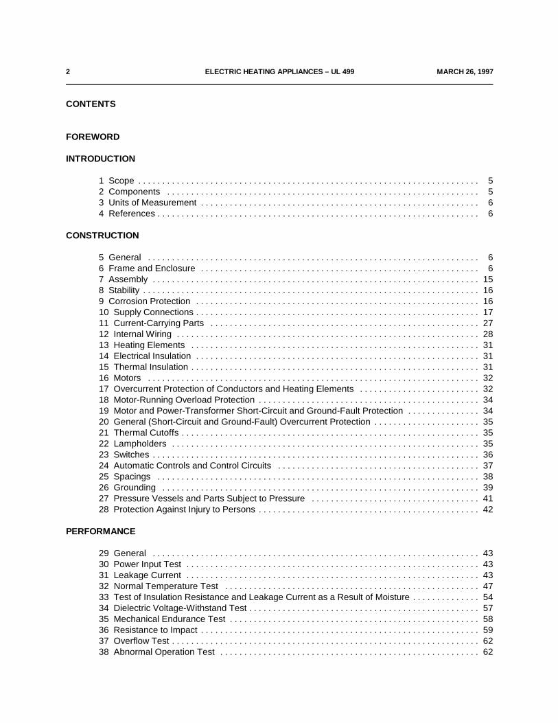
CONTENTS
FOREWORD
INTRODUCTION
1 Scope . . . . . . . . . . . . . . . . . . . . . . . . . . . . . . . . . . . . . . . . . . . . . . . . . . . . . . . . . . . . . . . . . . . . . . . 52 Components . . . . . . . . . . . . . . . . . . . . . . . . . . . . . . . . . . . . . . . . . . . . . . . . . . . . . . . . . . . . . . . . . 53 Units of Measurement . . . . . . . . . . . . . . . . . . . . . . . . . . . . . . . . . . . . . . . . . . . . . . . . . . . . . . . . . . 64 References . . . . . . . . . . . . . . . . . . . . . . . . . . . . . . . . . . . . . . . . . . . . . . . . . . . . . . . . . . . . . . . . . . . 6
CONSTRUCTION
5 General . . . . . . . . . . . . . . . . . . . . . . . . . . . . . . . . . . . . . . . . . . . . . . . . . . . . . . . . . . . . . . . . . . . . . 66 Frame and Enclosure . . . . . . . . . . . . . . . . . . . . . . . . . . . . . . . . . . . . . . . . . . . . . . . . . . . . . . . . . . 67 Assembly . . . . . . . . . . . . . . . . . . . . . . . . . . . . . . . . . . . . . . . . . . . . . . . . . . . . . . . . . . . . . . . . . . . . 158 Stability . . . . . . . . . . . . . . . . . . . . . . . . . . . . . . . . . . . . . . . . . . . . . . . . . . . . . . . . . . . . . . . . . . . . . . 169 Corrosion Protection . . . . . . . . . . . . . . . . . . . . . . . . . . . . . . . . . . . . . . . . . . . . . . . . . . . . . . . . . . . 1610 Supply Connections . . . . . . . . . . . . . . . . . . . . . . . . . . . . . . . . . . . . . . . . . . . . . . . . . . . . . . . . . . . 1711 Current-Carrying Parts . . . . . . . . . . . . . . . . . . . . . . . . . . . . . . . . . . . . . . . . . . . . . . . . . . . . . . . . 2712 Internal Wiring . . . . . . . . . . . . . . . . . . . . . . . . . . . . . . . . . . . . . . . . . . . . . . . . . . . . . . . . . . . . . . . 2813 Heating Elements . . . . . . . . . . . . . . . . . . . . . . . . . . . . . . . . . . . . . . . . . . . . . . . . . . . . . . . . . . . . 3114 Electrical Insulation . . . . . . . . . . . . . . . . . . . . . . . . . . . . . . . . . . . . . . . . . . . . . . . . . . . . . . . . . . . 3115 Thermal Insulation . . . . . . . . . . . . . . . . . . . . . . . . . . . . . . . . . . . . . . . . . . . . . . . . . . . . . . . . . . . . 3116 Motors . . . . . . . . . . . . . . . . . . . . . . . . . . . . . . . . . . . . . . . . . . . . . . . . . . . . . . . . . . . . . . . . . . . . . 3217 Overcurrent Protection of Conductors and Heating Elements . . . . . . . . . . . . . . . . . . . . . . . . . 3218 Motor-Running Overload Protection . . . . . . . . . . . . . . . . . . . . . . . . . . . . . . . . . . . . . . . . . . . . . . 3419 Motor and Power-Transformer Short-Circuit and Ground-Fault Protection . . . . . . . . . . . . . . . 3420 General (Short-Circuit and Ground-Fault) Overcurrent Protection . . . . . . . . . . . . . . . . . . . . . . 3521 Thermal Cutoffs . . . . . . . . . . . . . . . . . . . . . . . . . . . . . . . . . . . . . . . . . . . . . . . . . . . . . . . . . . . . . . 3522 Lampholders . . . . . . . . . . . . . . . . . . . . . . . . . . . . . . . . . . . . . . . . . . . . . . . . . . . . . . . . . . . . . . . . 3523 Switches . . . . . . . . . . . . . . . . . . . . . . . . . . . . . . . . . . . . . . . . . . . . . . . . . . . . . . . . . . . . . . . . . . . . 3624 Automatic Controls and Control Circuits . . . . . . . . . . . . . . . . . . . . . . . . . . . . . . . . . . . . . . . . . . 3725 Spacings . . . . . . . . . . . . . . . . . . . . . . . . . . . . . . . . . . . . . . . . . . . . . . . . . . . . . . . . . . . . . . . . . . . 3826 Grounding . . . . . . . . . . . . . . . . . . . . . . . . . . . . . . . . . . . . . . . . . . . . . . . . . . . . . . . . . . . . . . . . . . 3927 Pressure Vessels and Parts Subject to Pressure . . . . . . . . . . . . . . . . . . . . . . . . . . . . . . . . . . . 4128 Protection Against Injury to Persons . . . . . . . . . . . . . . . . . . . . . . . . . . . . . . . . . . . . . . . . . . . . . . 42
PERFORMANCE
29 General . . . . . . . . . . . . . . . . . . . . . . . . . . . . . . . . . . . . . . . . . . . . . . . . . . . . . . . . . . . . . . . . . . . . 4330 Power Input Test . . . . . . . . . . . . . . . . . . . . . . . . . . . . . . . . . . . . . . . . . . . . . . . . . . . . . . . . . . . . . 4331 Leakage Current . . . . . . . . . . . . . . . . . . . . . . . . . . . . . . . . . . . . . . . . . . . . . . . . . . . . . . . . . . . . . 4332 Normal Temperature Test . . . . . . . . . . . . . . . . . . . . . . . . . . . . . . . . . . . . . . . . . . . . . . . . . . . . . 4733 Test of Insulation Resistance and Leakage Current as a Result of Moisture . . . . . . . . . . . . . . 5434 Dielectric Voltage-Withstand Test . . . . . . . . . . . . . . . . . . . . . . . . . . . . . . . . . . . . . . . . . . . . . . . . 5735 Mechanical Endurance Test . . . . . . . . . . . . . . . . . . . . . . . . . . . . . . . . . . . . . . . . . . . . . . . . . . . . 5836 Resistance to Impact . . . . . . . . . . . . . . . . . . . . . . . . . . . . . . . . . . . . . . . . . . . . . . . . . . . . . . . . . . 5937 Overflow Test . . . . . . . . . . . . . . . . . . . . . . . . . . . . . . . . . . . . . . . . . . . . . . . . . . . . . . . . . . . . . . . . 6238 Abnormal Operation Test . . . . . . . . . . . . . . . . . . . . . . . . . . . . . . . . . . . . . . . . . . . . . . . . . . . . . . 62

JULY 17, 1998 ELECTRIC HEATING APPLIANCES – UL 499 3
39 Testing of Component Switches and Control Devices . . . . . . . . . . . . . . . . . . . . . . . . . . . . . . . . 6740 Strain Relief Test . . . . . . . . . . . . . . . . . . . . . . . . . . . . . . . . . . . . . . . . . . . . . . . . . . . . . . . . . . . . . 7040A Push-Back Relief Test . . . . . . . . . . . . . . . . . . . . . . . . . . . . . . . . . . . . . . . . . . . . . . . . . . . . . . . . 7041 Test for Permanence of Cord Tag for Outdoor-Use Heating Appliances with Power-Supply
Cords Less than 6 Feet (1.8 m) . . . . . . . . . . . . . . . . . . . . . . . . . . . . . . . . . . . . . . . . . . . . . . 70
MANUFACTURING AND PRODUCTION-LINE TESTS
42 Production-Line Dielectric Voltage-Withstand Test . . . . . . . . . . . . . . . . . . . . . . . . . . . . . . . . . . 7143 Polarization and Grounding Continuity Tests . . . . . . . . . . . . . . . . . . . . . . . . . . . . . . . . . . . . . . . 72
RATINGS
44 Details . . . . . . . . . . . . . . . . . . . . . . . . . . . . . . . . . . . . . . . . . . . . . . . . . . . . . . . . . . . . . . . . . . . . . 73
MARKINGS
45 Details . . . . . . . . . . . . . . . . . . . . . . . . . . . . . . . . . . . . . . . . . . . . . . . . . . . . . . . . . . . . . . . . . . . . . 7346 Instructions . . . . . . . . . . . . . . . . . . . . . . . . . . . . . . . . . . . . . . . . . . . . . . . . . . . . . . . . . . . . . . . . . . 80
ELECTRODE-TYPE HEATING APPLIANCES
47 Scope . . . . . . . . . . . . . . . . . . . . . . . . . . . . . . . . . . . . . . . . . . . . . . . . . . . . . . . . . . . . . . . . . . . . . . 8048 General . . . . . . . . . . . . . . . . . . . . . . . . . . . . . . . . . . . . . . . . . . . . . . . . . . . . . . . . . . . . . . . . . . . . 8049 Construction . . . . . . . . . . . . . . . . . . . . . . . . . . . . . . . . . . . . . . . . . . . . . . . . . . . . . . . . . . . . . . . . . 8050 Operation Test . . . . . . . . . . . . . . . . . . . . . . . . . . . . . . . . . . . . . . . . . . . . . . . . . . . . . . . . . . . . . . . 8151 Vaporizer-Operation Test . . . . . . . . . . . . . . . . . . . . . . . . . . . . . . . . . . . . . . . . . . . . . . . . . . . . . . 8252 Leakage Current Test . . . . . . . . . . . . . . . . . . . . . . . . . . . . . . . . . . . . . . . . . . . . . . . . . . . . . . . . . 8253 Disassembly and Reassembly Test . . . . . . . . . . . . . . . . . . . . . . . . . . . . . . . . . . . . . . . . . . . . . . 8354 Markings . . . . . . . . . . . . . . . . . . . . . . . . . . . . . . . . . . . . . . . . . . . . . . . . . . . . . . . . . . . . . . . . . . . . 8455 Operating Instructions . . . . . . . . . . . . . . . . . . . . . . . . . . . . . . . . . . . . . . . . . . . . . . . . . . . . . . . . . 8556 Label Adhesion Tests . . . . . . . . . . . . . . . . . . . . . . . . . . . . . . . . . . . . . . . . . . . . . . . . . . . . . . . . . 85
THERMOSTAT OVERRIDE UNITS
57 General . . . . . . . . . . . . . . . . . . . . . . . . . . . . . . . . . . . . . . . . . . . . . . . . . . . . . . . . . . . . . . . . . . . . 8658 Temperature Test . . . . . . . . . . . . . . . . . . . . . . . . . . . . . . . . . . . . . . . . . . . . . . . . . . . . . . . . . . . . 8759 Overload Tests . . . . . . . . . . . . . . . . . . . . . . . . . . . . . . . . . . . . . . . . . . . . . . . . . . . . . . . . . . . . . . 87
APPENDIX A
Standards for Components . . . . . . . . . . . . . . . . . . . . . . . . . . . . . . . . . . . . . . . . . . . . . . . . . . . . . . . A1

4 ELECTRIC HEATING APPLIANCES – UL 499 MARCH 26, 1997
FOREWORD
A. This Standard contains basic requirements for products covered by UnderwritersLaboratories Inc. (UL) under its Follow-Up Service for this category within thelimitations given below and in the Scope section of this Standard. These requirementsare based upon sound engineering principles, research, records of tests and fieldexperience, and an appreciation of the problems of manufacture, installation, and usederived from consultation with and information obtained from manufacturers, users,inspection authorities, and others having specialized experience. They are subject torevision as further experience and investigation may show is necessary or desirable.
B. The observance of the requirements of this Standard by a manufacturer is one ofthe conditions of the continued coverage of the manufacturer's product.
C. A product which complies with the text of this Standard will not necessarily bejudged to comply with the Standard if, when examined and tested, it is found to haveother features which impair the level of safety contemplated by these requirements.
D. A product employing materials or having forms of construction differing from thosedetailed in the requirements of this Standard may be examined and tested accordingto the intent of the requirements and, if found to be substantially equivalent, may bejudged to comply with the Standard.
E. UL, in performing its functions in accordance with its objectives, does not assumeor undertake to discharge any responsibility of the manufacturer or any other party.The opinions and findings of UL represent its professional judgment given with dueconsideration to the necessary limitations of practical operation and state of the artat the time the Standard is processed. UL shall not be responsible to anyone for theuse of or reliance upon this Standard by anyone. UL shall not incur any obligation orliability for damages, including consequential damages, arising out of or in connectionwith the use, interpretation of or reliance upon this Standard.
F. Many tests required by the Standards of UL are inherently hazardous andadequate safeguards for personnel and property shall be employed in conductingsuch tests.
MARCH 26, 1997 ELECTRIC HEATING APPLIANCES – UL 499 5
INTRODUCTION
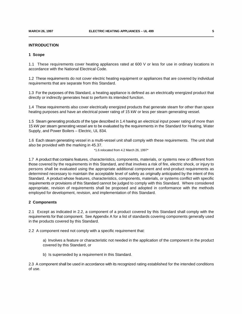
1 Scope
1.1 These requirements cover heating appliances rated at 600 V or less for use in ordinary locations inaccordance with the National Electrical Code.
1.2 These requirements do not cover electric heating equipment or appliances that are covered by individualrequirements that are separate from this Standard.
1.3 For the purposes of this Standard, a heating appliance is defined as an electrically energized product thatdirectly or indirectly generates heat to perform its intended function.
1.4 These requirements also cover electrically energized products that generate steam for other than spaceheating purposes and have an electrical power rating of 15 kW or less per steam generating vessel.
1.5 Steam generating products of the type described in 1.4 having an electrical input power rating of more than15 kW per steam generating vessel are to be evaluated by the requirements in the Standard for Heating, WaterSupply, and Power Boilers – Electric, UL 834.
1.6 Each steam generating vessel in a multi-vessel unit shall comply with these requirements. The unit shallalso be provided with the marking in 45.37.
*1.6 relocated from 4.2 March 26, 1997*
1.7 A product that contains features, characteristics, components, materials, or systems new or different fromthose covered by the requirements in this Standard, and that involves a risk of fire, electric shock, or injury topersons shall be evaluated using the appropriate additional component and end-product requirements asdetermined necessary to maintain the acceptable level of safety as originally anticipated by the intent of thisStandard. A product whose features, characteristics, components, materials, or systems conflict with specificrequirements or provisions of this Standard cannot be judged to comply with this Standard. Where consideredappropriate, revision of requirements shall be proposed and adopted in conformance with the methodsemployed for development, revision, and implementation of this Standard.
2 Components
2.1 Except as indicated in 2.2, a component of a product covered by this Standard shall comply with therequirements for that component. See Appendix A for a list of standards covering components generally usedin the products covered by this Standard.
2.2 A component need not comply with a specific requirement that:
a) Involves a feature or characteristic not needed in the application of the component in the productcovered by this Standard, or
b) Is superseded by a requirement in this Standard.
2.3 A component shall be used in accordance with its recognized rating established for the intended conditionsof use.
6 ELECTRIC HEATING APPLIANCES – UL 499 MARCH 26, 1997
2.4 Specific components are recognized as being incomplete in construction features or restricted inperformance capabilities. Such components are intended for use only under limited conditions, such as certaintemperatures not exceeding specified limits and shall be restricted to use only under those specific conditionsfor which they have been recognized.
3 Units of Measurement
3.1 If a value for measurement as given in these requirements is followed by an equivalent value in other units,in parenthesis, the second value may be only approximate. The first stated value is the requirement.
3.2 Unless indicated otherwise all voltage and current values mentioned in this Standard are root-mean-square(rms).
4 References
4.1 Any undated reference to a code or standard appearing in the requirements of this Standard shall beinterpreted as referring to the latest edition of that code or standard.
CONSTRUCTION
5 General
5.1 A heating appliance intended for use in a hazardous location is judged on the basis of its compliance withthe requirements in this Standard, and further appropriate examination and tests to determine whether it isacceptable for the purpose.
5.2 Only materials that are acceptable for the particular use shall be used in a heating appliance. A heatingappliance shall be made and finished with the degree of uniformity and grade of workmanship practicable ina well-equipped factory.
5.3 If the operation of a heating appliance involves the generation and confining under pressure of steam orother gas, consideration is to be given to the possibility of risk of explosion incident to such operation. Thisapplies in the case of a product having immersed electrodes, where the electrolysis of water may result in theaccumulation of oxygen and hydrogen. The product is not acceptable unless its strength has been investigatedwith respect to any risk of explosion that may be involved.
6 Frame and Enclosure
6.1 The frame and enclosure of a heating appliance shall be strong and rigid to resist the abuses to beencountered during intended use. The degree of resistance inherent in the product shall preclude total andpartial collapse with the attendant reduction of spacings, loosening or displacement of parts, and other defectswhich alone or in combination constitute an increase in the risk of fire, electric shock, or injury to persons.
6.2 A vaporizer water reservoir of glass or similar material that might, upon breaking, cause skin lacerationsshall be resistant to thermal-shock and impact.
MARCH 26, 1997 ELECTRIC HEATING APPLIANCES – UL 499 7
6.3 A heating appliance shall be provided with an enclosure of material acceptable for the application, thatshall house all electrical parts, except a supply cord and a recessed open-wire-element unit as mentioned in13.3, that may result in risk of electric shock or injury to persons under any condition of use. If a heater is forpermanent installation (intended for permanent connection to the power supply), the enclosure shall beprovided with means for mounting in the intended manner and shall be furnished with any necessary fittings,such as brackets, hangers, or the like.
6.4 If openings for ventilation are provided in the enclosure of a heating appliance or in an externally mountedcomponent intended for permanent connection to the power supply, they shall be so located that they will notvent into concealed spaces of a building structure, such as into false-ceiling space, into hollow spaces in thewall, and the like, when the product is installed.
6.5 Among the factors when an enclosure is being considered for acceptability, are its:
a) Physical strength,
b) Resistance to impact,
c) Moisture-absorptive properties,
d) Combustibility,
e) Resistance to corrosion, and
f) Resistance to distortion at temperatures to which the enclosure may be subjected under conditionsof use.
For a nonmetallic enclosure, all of these factors are to be considered with respect to thermal aging.
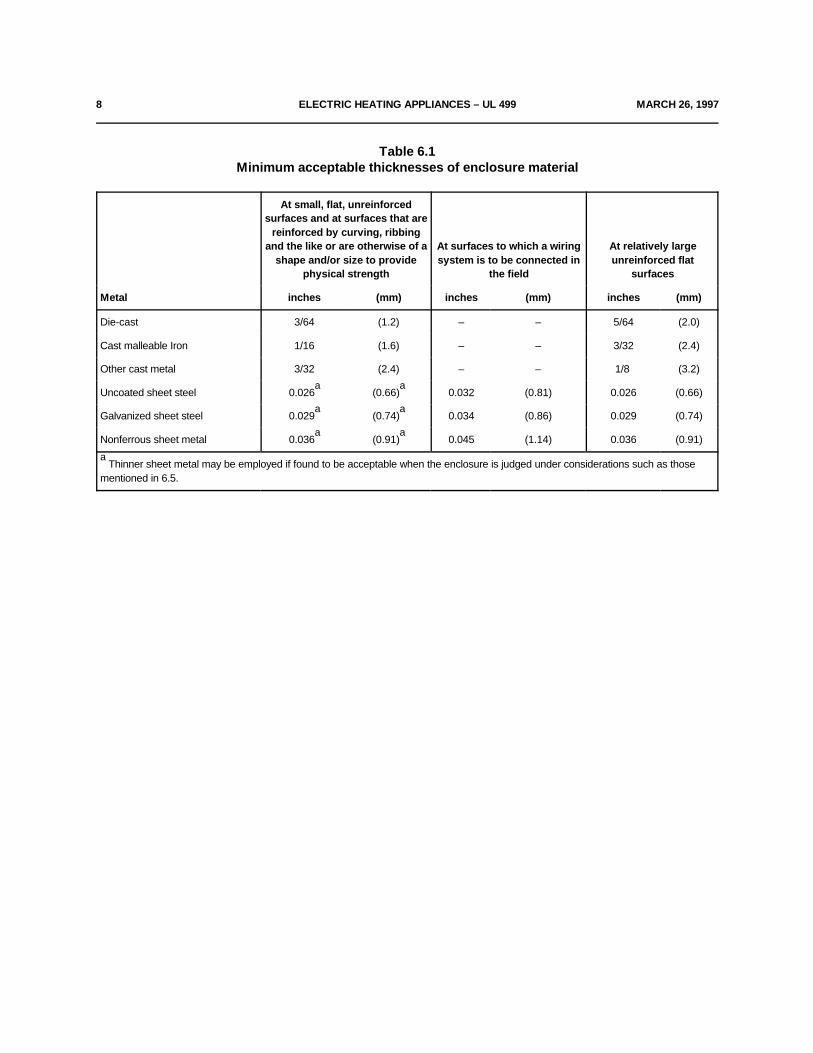
6.6 Cast- and sheet-metal portions of the enclosure shall be no thinner than indicated in Table 6.1 unless theenclosure complies with 6.5 and 6.7.
6.7 In addition to the factors in 6.5, an enclosure of sheet metal is to be considered with respect to its size andshape, the thickness of metal and the intended use of the product.
6.8 Electrical parts of a heating appliance, including open-wire elements, shall be so located or enclosed thatprotection against unintentional contact with uninsulated live parts will be provided (see also 23.6). Insulatedmotor brush caps do not require additional enclosure.
6.9 The enclosure shall be such that molten metal, burning insulation, flaming particles, or the like, is not likelyto fall on combustible materials, including the surface upon which the enclosure is supported.
8 ELECTRIC HEATING APPLIANCES – UL 499 MARCH 26, 1997
Table 6.1Minimum acceptable thicknesses of enclosure material
Metal inches (mm) inches (mm) inches (mm)
At small, flat, unreinforcedsurfaces and at surfaces that are
reinforced by curving, ribbingand the like or are otherwise of a At surfaces to which a wiring At relatively large
shape and/or size to provide system is to be connected in unreinforced flatphysical strength the field surfaces
Die-cast 3/64 (1.2) – – 5/64 (2.0)
Cast malleable Iron 1/16 (1.6) – – 3/32 (2.4)
Other cast metal 3/32 (2.4) – – 1/8 (3.2)
Uncoated sheet steel 0.026 (0.66) 0.032 (0.81) 0.026 (0.66)a a
Galvanized sheet steel 0.029 (0.74) 0.034 (0.86) 0.029 (0.74)a a
Nonferrous sheet metal 0.036 (0.91) 0.045 (1.14) 0.036 (0.91)a a
Thinner sheet metal may be employed if found to be acceptable when the enclosure is judged under considerations such as thosea
mentioned in 6.5.
MARCH 26, 1997 ELECTRIC HEATING APPLIANCES – UL 499 9
6.10 The requirement in 6.9 necessitates use of a barrier of metal, phenolic, urea, ceramic or similar material:
a) Under a motor unless:
1) The structural parts of the motor or of the product provide the equivalent of such a barrier.
2) The protection provided with the motor is such that no burning insulation or molten materialfalls to the surface that supports the product when the motor is energized under each of thefollowing fault conditions:
i) Open main winding,
ii) Open starting winding, and
iii) Starting switch short-circuited, or
3) The motor is provided with a thermal motor protector (a protective device that is sensitiveto both temperature and current) that restricts the temperature of the motor windings frombecoming more than 125EC (257EF) under the maximum load under which the motor runswithout causing the protector to cycle, and from becoming more than 150EC (302EF) with therotor of the motor locked.
4) The motor complies with the requirements for impedance-protected motors.
b) Under wiring, unless it complies with the VW-1 (Vertical-Specimen) Flame Test described in Section1080 of the Reference Standard for Electrical Wires, Cables, and Flexible Cords, UL 1581.
6.11 The requirement in 6.9 also necessitates that a switch, transformer, relay, solenoid, or the like, beindividually and completely enclosed except at terminals, unless it can be shown that malfunction of thecomponent is not likely to result in a fire, or unless there are no openings in the bottom of the enclosure. Anopening in the bottom of the enclosure is not acceptable if it is located directly below field- or factory-madesplices or overload or overcurrent protective devices.
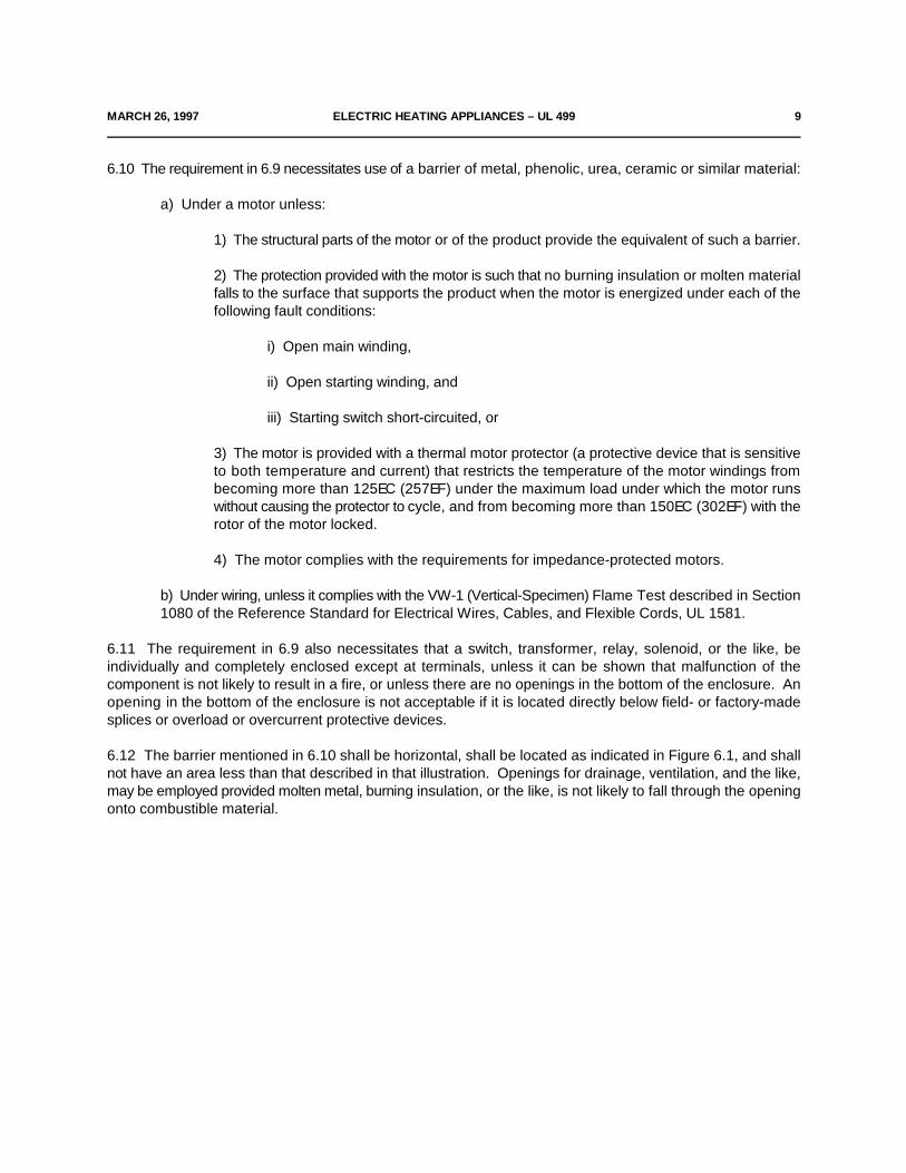
6.12 The barrier mentioned in 6.10 shall be horizontal, shall be located as indicated in Figure 6.1, and shallnot have an area less than that described in that illustration. Openings for drainage, ventilation, and the like,may be employed provided molten metal, burning insulation, or the like, is not likely to fall through the openingonto combustible material.
10 ELECTRIC HEATING APPLIANCES – UL 499 MARCH 26, 1997
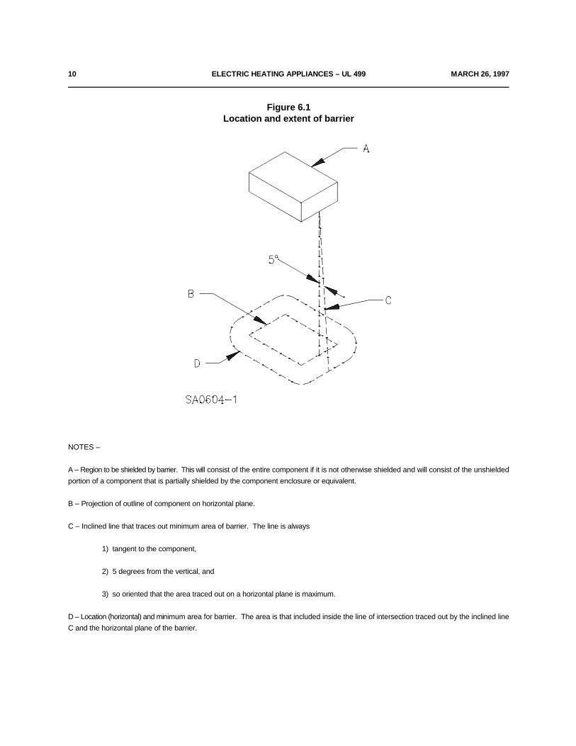
Figure 6.1Location and extent of barrier
NOTES –
A – Region to be shielded by barrier. This will consist of the entire component if it is not otherwise shielded and will consist of the unshieldedportion of a component that is partially shielded by the component enclosure or equivalent.
B – Projection of outline of component on horizontal plane.
C – Inclined line that traces out minimum area of barrier. The line is always
1) tangent to the component,
2) 5 degrees from the vertical, and
3) so oriented that the area traced out on a horizontal plane is maximum.
D – Location (horizontal) and minimum area for barrier. The area is that included inside the line of intersection traced out by the inclined lineC and the horizontal plane of the barrier.
MARCH 26, 1997 ELECTRIC HEATING APPLIANCES – UL 499 11
6.13 The criteria for judging a heating appliance enclosure, other than as described in 6.8, are given in 6.15and 6.16 and in the following items and related illustrations:
a) An opening in the enclosure is acceptable if the probe (illustrated in Figure 6.2), when inserted intothe opening, cannot be made to touch any uninsulated live part of film-coated wire that involves a riskof electric shock. The probe is to be applied to any depth that the opening will permit; and shall berotated and articulated in all possible configurations before, during and after insertion.
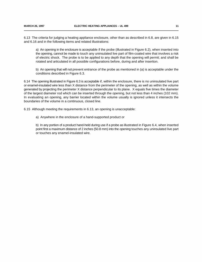
b) An opening that will not prevent entrance of the probe as mentioned in (a) is acceptable under theconditions described in Figure 6.3.
6.14 The opening illustrated in Figure 6.3 is acceptable if, within the enclosure, there is no uninsulated live partor enamel-insulated wire less than X distance from the perimeter of the opening, as well as within the volumegenerated by projecting the perimeter X distance perpendicular to its plane. X equals five times the diameterof the largest diameter rod which can be inserted through the opening, but not less than 4 inches (102 mm).In evaluating an opening, any barrier located within the volume usually is ignored unless it intersects theboundaries of the volume in a continuous, closed line.
6.15 Although meeting the requirements in 6.13, an opening is unacceptable:
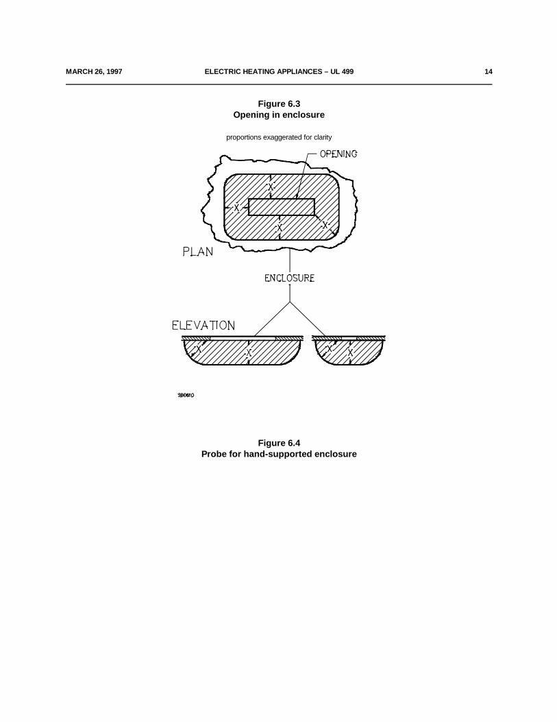
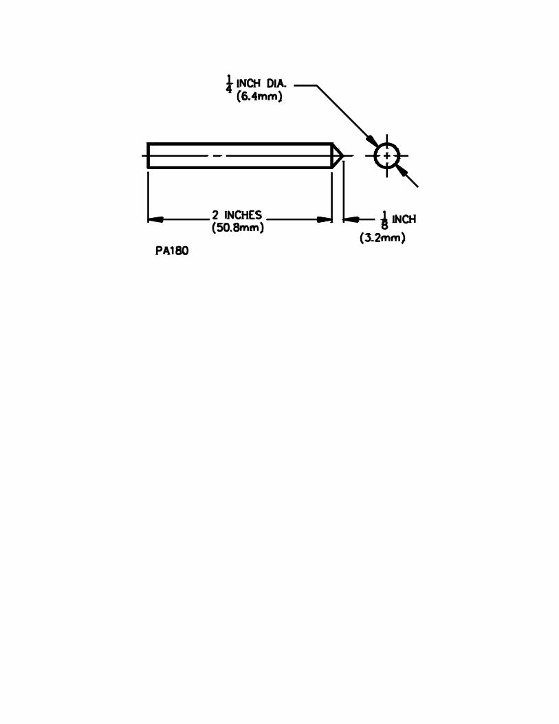
a) Anywhere in the enclosure of a hand-supported product or
b) In any portion of a product hand-held during use if a probe as illustrated in Figure 6.4, when insertedpoint first a maximum distance of 2 inches (50.8 mm) into the opening touches any uninsulated live partor touches any enamel-insulated wire.

12 ELECTRIC HEATING APPLIANCES – UL 499 MARCH 26, 1997
Figure 6.2Articulate probe with web stop

MARCH 26, 1997 ELECTRIC HEATING APPLIANCES – UL 499 14
Figure 6.3Opening in enclosure
proportions exaggerated for clarity
Figure 6.4Probe for hand-supported enclosure
16 ELECTRIC HEATING APPLIANCES – UL 499 MARCH 26, 1997
6.16 If a marking draws the user's attention to a hole of any size in the enclosure for the adjustment of athermostat or for a similar activity, it shall not be possible to damage insulation or contact uninsulated live partsthrough the hole with a 1/16-inch (1.6-mm) diameter rod.
6.17 During the examination of a heating appliance in connection with the requirements in 6.8 – 6.13, a partof the outer enclosure that may be removed without the use of tools by the user of the product (for theattachment of accessories, for access to means for making operating adjustments, or for other reasons) is tobe disregarded – that is, it is not to be assumed that the part in question affords protection against risk of electricshock. A warning marking, such as that specified in 45.6 is not considered to eliminate this risk of electricshock.
6.18 Any moving parts, such as rotors of motors, chains, pulleys, belts, and gears, shall be enclosed orguarded to reduce the risk of injury to persons.
6.19 With reference to the requirement in 6.18, the degree of protection required of the enclosure dependsupon the general design and intended use of the product. The factors to be taken into consideration in judgingthe acceptability of exposed moving parts are:
a) The degree of exposure,
b) The sharpness of the moving parts,
c) The likelihood of unintentional contact with the moving parts,
d) The speed of movement of those parts, and
e) The likelihood of fingers, arms, or clothing being drawn into the moving parts – such as at pointswhere gears mesh, where belts travel onto a pulley or where moving parts close in a pinching orshearing action.
6.20 The door or cover of an enclosure shall be provided with a means for securing it in place in the closedposition.
6.21 The door or cover of an enclosure shall be hinged or otherwise attached in an equivalent manner if it givesaccess to any overload protective device whose functioning requires renewal, or if it is necessary to open thecover in connection with the operation of the protective device. Such a door or cover shall be provided with alatch or the equivalent, and shall be tight-fitting or shall overlap the surface of the enclosure around theopening.
6.22 A component of a heating appliance that is likely to need inspection, replacement, cleaning, or otherservicing shall be as accessible as possible. Except as noted in 6.23, the component shall be readily accessiblewithout the use of special tools – tools not available to other than service personnel – if it is intended to bemanually operated or adjusted or periodically serviced.
6.23 If a product is intended primarily for use in public places, such as gas stations, theaters, bus terminals,or the like:
a) The construction may be such that special tools are required to gain access to components that arelikely to need inspection, replacement, cleaning, adjustment, or other servicing.
b) A door or cover giving access to an overload protective device need not be provided with a hinge,
latch, or equivalent if the cover intended must be in place to perform its function.
MARCH 26, 1997 ELECTRIC HEATING APPLIANCES – UL 499 18
6.24 The bulb and capillary tube of a thermostat shall be protected from physical damage if such damage ofthe tube or bulb may result in a risk of fire.
6.25 The mounting means of a wall-mounted insecticide vaporizer shall be such that:
a) The product will be secured against tipping or dislodgement as a result of unintentional contact withthe body of the product itself or with the power-supply cord, and
b) The removal of the vaporizer can be accomplished readily, if it is necessary that the vaporizer beremoved from its mounting for cleaning, refilling, or other servicing.
6.26 With reference to the requirement in 6.25, a simple keyhole slot or hanger ring is not acceptable as amounting means unless other provisions are made, such that spillage of the insecticide will not result fromtipping or dislodgement of the product.
6.27 If the enclosure of an insecticide vaporizer for wall mounting is of porcelain, glass, or other similarly brittlematerial, it shall not break or crack to the extent that uninsulated live parts will be exposed to contact, whendropped on a hardwood surface. The height through which the product is to be dropped is to be 8 ft (2.44 m)for a commercial-type vaporizer, and 6 ft (1.83 m) for a household product.
6.28 The sheath employed to enclose the heating element of an immersion-type heater for use with fuel oilshall be of steel, stainless steel, or other metal resistant to corrosion in fuel oil; brass, bronze, or copper is notconsidered acceptable for this application. The sheath employed to enclose the heating element of animmersion-type water heater shall be of a metal resistant to corrosion in water.
6.29 Openings provided in a soldering tool, such as for ventilating purposes, shall be of such size andorientation with respect to the soldering tip that entry of falling or dripping molten solder, or unintentionalinsertion of solder wire is not likely to contact, bridge, or otherwise reduce the spacings between uninsulatedlive parts of opposite polarity, or uninsulated live parts and accessible dead metal parts. Consideration shallbe given to the orientation of the soldering tool during use.
6.30 A cord-connected product that is provided with keyhole slots, notches, hanger holes, or the like, formounting the product on a wall shall be constructed in such a manner that the mounting means shall not beaccessible without removing the product from the supporting means.
6.31 When determining compliance with 6.30, any part of the enclosure or barriers that can be removedwithout the use of tools to gain access to the mounting means are to be removed.
6.32 A keyhole slot, notch, or hanger hole shall be located so that the supporting screws or the like cannotdamage any electrical insulation or contact uninsulated current-carrying parts of the product.
7 Assembly
7.1 A soldering iron, or other cord-connected heating appliance that is likely to be laid on combustible materialshall be provided with a stand of noncombustible material upon which it may be placed when not in use, unlessthe temperature attained by the product is not high enough to cause the ignition of the combustible material.
7.2 The stand may be a separate device or attached to the product, except that an integral type of stand isrequired for a charcoal ignitor.
19 ELECTRIC HEATING APPLIANCES – UL 499 MARCH 26, 1997
7.3 A switch, lampholder, attachment-plug receptacle, or plug-type connector provided as a part of a heatingappliance shall be secured so that it is not likely to turn.
7.4 Uninsulated live parts shall be so secured to the base or surface that they are not likely to turn or shift inposition as the result of stresses if such motion results in a reduction of spacings below the minimum requiredin 25.1.1.1 – 25.1.1.4.
7.5 Friction between surfaces is not acceptable as a means to keep live parts or components from shifting orturning. A lock washer, properly applied, is acceptable for this purpose.
8 Stability
8.1 The stability of a heating appliance shall be such that it will not be overturned readily during use.
8.2 A portable household heating appliance in which liquid is heated to a temperature greater than 115EF(46EC) is to be placed on a plane inclined at an angle of 15 degrees to the horizontal. The product is to bepositioned and loaded with whatever combination of separable components, liquid, or other media (material)that results in the maximum tendency to overturn under conditions of intended use. The product is to containat least 5 oz (148 mL) of liquid. The product is to be prevented from sliding on the inclined surface. Theproduct shall not overturn as a result of this test.
8.3 To determine if a vaporizer in which water is heated complies with the requirements of 8.1, the productshall not overturn when subjected to the test described in 8.4.
8.4 The vaporizer is to be placed at any position of use on a plane inclined at an angle of 30 degrees to thehorizontal. For this test the product is to be assembled and filled with liquid in any condition simulatingoperating conditions, so as to result in the maximum tendency to overturn. The product is to be supported sothat it does not slide on the inclined plane.
9 Corrosion Protection
9.1 Except as noted in 9.2, iron and steel parts shall be protected against corrosion by enameling, galvanizing,plating, or other means, if the deterioration of such unprotected parts would be likely to result in risk of fire orelectric shock.
9.2 In certain equipment where the oxidation of steel is not likely to be accelerated due to the exposure of metalto air and moisture or other oxidizing influence – thickness of metal and temperature also being factors –surfaces of sheet steel within an enclosure may not be required to be protected against corrosion. Cast-ironparts are not required to be protected against corrosion. A sheath employed on a heating element operatingin air and terminal parts attached directly to the heating element need not be protected against corrosion.
9.3 The aging characteristics of plating or other finish used in a heating appliance shall be such thatdeterioration of the finish will not result eventually in unacceptable performance of the product.
MARCH 26, 1997 ELECTRIC HEATING APPLIANCES – UL 499 20
10 Supply Connections
10.1 Permanently-connected products
10.1.1 General
10.1.1.1 Except as noted in 10.1.1.2 and 10.2.1.2, a product intended for permanent connection electricallyto the power supply shall have provision for connection of one of the wiring systems that in accordance with theNational Electrical Code, ANSI/NFPA 70, would be acceptable for the product.
10.1.1.2 An insecticide vaporizer intended for wall mounting may employ a flexible cord for connection to thepower supply, provided that the length of the cord is not more than 3 ft (0.9 m) for a commercial product andnot more than 6 ft (1.8 m) for a household product.
10.1.1.3 The location of a terminal box or compartment in which power-supply connections to a heatingappliance intended to be permanently connected electrically are to be made shall be such that theseconnections may be readily inspected after the product is installed as intended.
10.1.1.4 A terminal compartment intended for the connection of a supply raceway shall be so attached to theproduct that it shall not turn with respect to the product.
10.1.1.5 An electrical component shall not be mounted on a part, such as the cover of a wiring-terminalcompartment, that must be removed for the purpose of making or inspecting field-wiring connections.
Exception: A single electrical component, such as a switch, a pilot light, or the like, may be mounted on a wiringcompartment cover provided that:
a) The component connecting leads are of such length to provide for the making, and examination,of field-wiring connections,
b) None of the component connections is to be field wired,
c) Strain relief is provided to prevent stress from being transmitted to the component wiringterminations, and complies with the strain relief test in 40.2,
d) The minimum size of the component leads is No. 18 AWG (0.82 mm ), and2
e) Wiring terminations on the component are recessed or protected by barriers of insulating materialor the equivalent that will provide protection from contact with wiring installed in the box, orunintentional contact during installation or inspection of field wiring.
10.1.2 Wiring terminals
10.1.2.1 A heating appliance intended for permanent connection to the power supply shall be provided withwiring terminals or leads for the connection of conductors having an ampacity of not less than 125 percent ofthe current rating of the product when the load is continuous (3 hours or more) and not less than the currentrating of the product when the load will be intermittent.
10.1.2.2 For the purpose of these requirements, wiring terminals are considered to be terminals to whichpower-supply or control connections will be made in the field when the product is installed. It is to be assumedthat 60EC (140EF) wire will be used for connections to a continuous-load type of heating appliance rated at 80

A or less and an intermittent-load type of heating appliance rated at 100 A or less. Wire rated for 75EC (167EF)will be assumed to be used with product rated in excess of these values.

22 ELECTRIC HEATING APPLIANCES – UL 499 MARCH 26, 1997
10.1.2.3 A wiring terminal shall be provided with a soldering lug or with a pressure wire connector securelyfastened in place for example, bolted or held by a screw, except that a wire-binding screw may be employedat a wiring terminal intended to accommodate a No. 10 AWG (5.3 mm ) or smaller conductor if upturned lugs2
or the equivalent are provided to hold the wire in position.
10.1.2.4 A wiring terminal shall not turn or shift in position. Friction between surfaces is not an acceptablemeans. An acceptable means may be by the use of two screws or rivets, by square shoulders or mortises, bya dowel pin, lug or offset, by a connecting strap or clip fitted into an adjacent part, or by some other equivalentmethod.
10.1.2.5 A wire-binding screw at a wiring terminal shall not be smaller than No. 10, except that a No. 8 screwmay be used at a terminal intended only for the connection of a No. 14 AWG (2.1 mm ) or smaller conductor,2
and a No. 6 screw may be used for the connection of a No. 16 or 18 AWG (1.3 or 0.82 mm ) control-circuit2
conductor.
10.1.2.6 A terminal plate tapped for a wire-binding screw shall be of metal not less than 0.050 inch (1.3 mm)thick, except that a plate not less than 0.030 inch (0.8 mm) thick is acceptable if the tapped threads haveacceptable mechanical strength. There shall be two or more full threads in the metal, which may be extrudedif necessary to provide the threads.
10.1.2.7 Upturned lugs or a cupped washer shall be capable of retaining a conductor of the size mentionedin 10.1.2.1, but not smaller than No. 14 AWG (2.1 mm ), under the head of the screw or the washer.2
10.1.2.8 A wire-binding screw shall thread into metal.
10.1.2.9 A heating appliance intended for connection to a grounded power-supply conductor and employing:
a) A lampholder or element holder of the Edison-screw-shell type,
b) A single-pole switch, or
c) A single-pole automatic control
shall have one terminal or lead identified for connection of the grounded conductor of the supply circuit. Theidentified terminal or lead shall be the one that is connected to screw shells of lampholders or element holders,and with no connection to single-pole switches or single-pole automatic controls, except as noted in 24.2.
10.1.2.10 A terminal provided for the connection of a grounded circuit conductor shall be made of or platedwith a metal white in color, or have the word "white" located adjacent to the terminal and shall be readilydistinguishable from the other terminals, or proper identification of that terminal shall be clearly shown in someother manner, such as on an attached wiring diagram. A lead intended for the connection of a grounded circuitconductor shall be finished to show a white or natural grey color and shall be distinguishable from the otherleads.
10.1.2.11 Except as noted in 10.1.2.12, the free length of a lead inside an outlet box or wiring compartmentshall be 6 inches (152 mm) or more if the lead is intended for field connection to an external circuit.
MARCH 26, 1997 ELECTRIC HEATING APPLIANCES – UL 499 23
10.1.2.12 A lead may be less than 6 inches (152 mm) in length if it is evident that the use of a longer lead mightresult in a risk of fire or electric shock.
10.1.2.13 The surface of an insulated lead intended solely for the connection of an equipment-groundingconductor shall be green with or without one or more yellow stripes, and no other lead in the field wiring areashall be so identified.
10.1.2.14 A wire-binding screw intended for the connection of an equipment-grounding conductor shall havea green-colored head that is hexagonal-shaped, slotted, or both. A pressure-wire connector intended forconnection of such a conductor shall be plainly identified by being marked "g", "gr", "gnd", "grounding", or thelike, or by a marking on the wiring diagram provided on the heating appliance. The wire-binding screw orpressure-wire connectors shall be so located that it is unlikely to be removed during the servicing of the product.
10.1.2.15 A terminal intended solely for connection of an equipment-grounding conductor shall be capableof securing a conductor of the size acceptable for the particular product, in accordance with the NationalElectrical Code, ANSI/NFPA 70.
10.2 Cord connected products
10.2.1 General
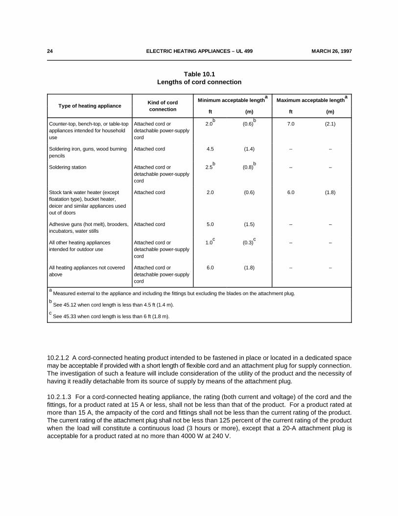
10.2.1.1 A cord-connected heating appliance shall be provided with a length of attached flexible cord and anattachment plug for connection to the supply circuit, or shall have male pin terminals that accommodate adetachable power-supply cord. The length of the cord shall be within the limits indicated in Table 10.1. Alldetachable power-supply cords and permanently-connected power-supply cords shall comply with therequirements of the Standard for Cord Sets and Power-Supply Cords, UL 817.
24 ELECTRIC HEATING APPLIANCES – UL 499 MARCH 26, 1997
Table 10.1Lengths of cord connection
Type of heating applianceKind of cordconnection
Minimum acceptable length Maximum acceptable lengtha a
ft (m) ft (m)
Counter-top, bench-top, or table-top Attached cord or 2.0 (0.6) 7.0 (2.1)appliances intended for household detachable power-supplyuse cord
b b
Soldering iron, guns, wood burning Attached cord 4.5 (1.4) – –pencils
Soldering station Attached cord or 2.5 (0.8) – –detachable power-supplycord
b b
Stock tank water heater (except Attached cord 2.0 (0.6) 6.0 (1.8)floatation type), bucket heater,deicer and similar appliances usedout of doors
Adhesive guns (hot melt), brooders, Attached cord 5.0 (1.5) – –incubators, water stills
All other heating appliances Attached cord or 1.0 (0.3) – –intended for outdoor use detachable power-supply
cord
c c
All heating appliances not covered Attached cord or 6.0 (1.8) – –above detachable power-supply
cord
Measured external to the appliance and including the fittings but excluding the blades on the attachment plug.a
See 45.12 when cord length is less than 4.5 ft (1.4 m).b
See 45.33 when cord length is less than 6 ft (1.8 m).c
10.2.1.2 A cord-connected heating product intended to be fastened in place or located in a dedicated spacemay be acceptable if provided with a short length of flexible cord and an attachment plug for supply connection.The investigation of such a feature will include consideration of the utility of the product and the necessity ofhaving it readily detachable from its source of supply by means of the attachment plug.
10.2.1.3 For a cord-connected heating appliance, the rating (both current and voltage) of the cord and thefittings, for a product rated at 15 A or less, shall not be less than that of the product. For a product rated atmore than 15 A, the ampacity of the cord and fittings shall not be less than the current rating of the product.The current rating of the attachment plug shall not be less than 125 percent of the current rating of the productwhen the load will constitute a continuous load (3 hours or more), except that a 20-A attachment plug isacceptable for a product rated at no more than 4000 W at 240 V.
JULY 17, 1998 ELECTRIC HEATING APPLIANCES – UL 499 25
10.2.1.4 The attachment plug of the power-supply cord of an appliance provided with a 15- or 20-amperegeneral-use receptacle shall be of the 3-wire grounding type. The attachment plug of the power-supply cordof an appliance provided with either a manually operated, line-connected, single pole switch for appliance on-off operation or an Edison-base lampholder shall be of the 2-wire polarized or 3-wire grounding type.
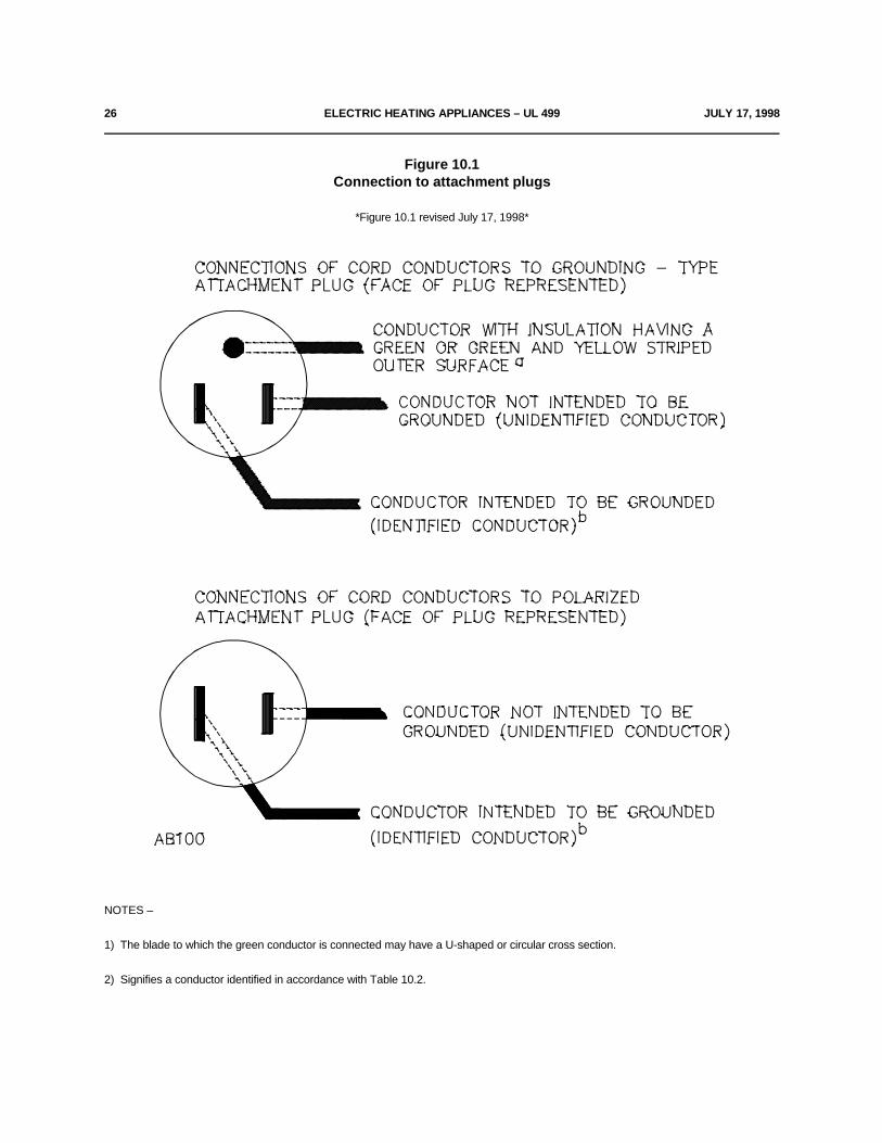
10.2.1.5 If a 3-wire grounding-type attachment plug or a 2-wire polarized attachment plug is provided, theattachment plug connections shall comply with Figure 10.1 and the polarity identification of the flexible cordshall comply with Table 10.2.
26 ELECTRIC HEATING APPLIANCES – UL 499 JULY 17, 1998
Figure 10.1Connection to attachment plugs
*Figure 10.1 revised July 17, 1998*
NOTES –
1) The blade to which the green conductor is connected may have a U-shaped or circular cross section.
2) Signifies a conductor identified in accordance with Table 10.2.
JULY 17, 1998 ELECTRIC HEATING APPLIANCES – UL 499 22A
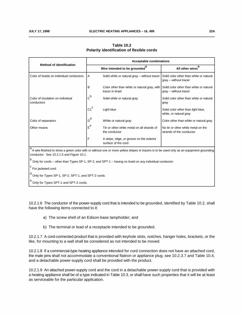
Table 10.2Polarity identification of flexible cords
Method of identificationAcceptable combinations
Wire intended to be grounded All other wiresa a
Color of braids on individual conductors A Solid white or natural gray – without tracer Solid color other than white or naturalgray – without tracer
B Color other than white or natural gray, with Solid color other than white or naturaltracer in braid gray – without tracer
Color of insulation on individual C Solid white or natural gray Solid color other than white or naturalconductors gray
b
C1 Light blue Solid color other than light blue,c
white, or natural gray
Color of separators D White or natural gray Color other than white or natural gray d
Other means E Tin or other white metal on all strands of No tin or other white metal on thee
the conductor strands of the conductor
F A stripe, ridge, or groove on the exteriorsurface of the cord
A wire finished to show a green color with or without one or more yellow stripes or tracers is to be used only as an equipment groundinga
conductor. See 10.2.1.5 and Figure 10.1.
Only for cords – other than Types SP-1, SP-2, and SPT-1 – having no braid on any individual conductor.b
For jacketed cord.c
Only for Types SP-1, SP-2, SPT-1, and SPT-2 cords.d
Only for Types SPT-1 and SPT-2 cords.e
10.2.1.6 The conductor of the power-supply cord that is intended to be grounded, identified by Table 10.2, shallhave the following items connected to it:
a) The screw shell of an Edison-base lampholder; and
b) The terminal or lead of a receptacle intended to be grounded.
10.2.1.7 A cord-connected product that is provided with keyhole slots, notches, hanger holes, brackets, or thelike, for mounting to a wall shall be considered as not intended to be moved.
10.2.1.8 If a commercial-type heating appliance intended for cord connection does not have an attached cord,the male pins shall not accommodate a conventional flatiron or appliance plug, see 10.2.3.7 and Table 10.4,and a detachable power-supply cord shall be provided with the product.
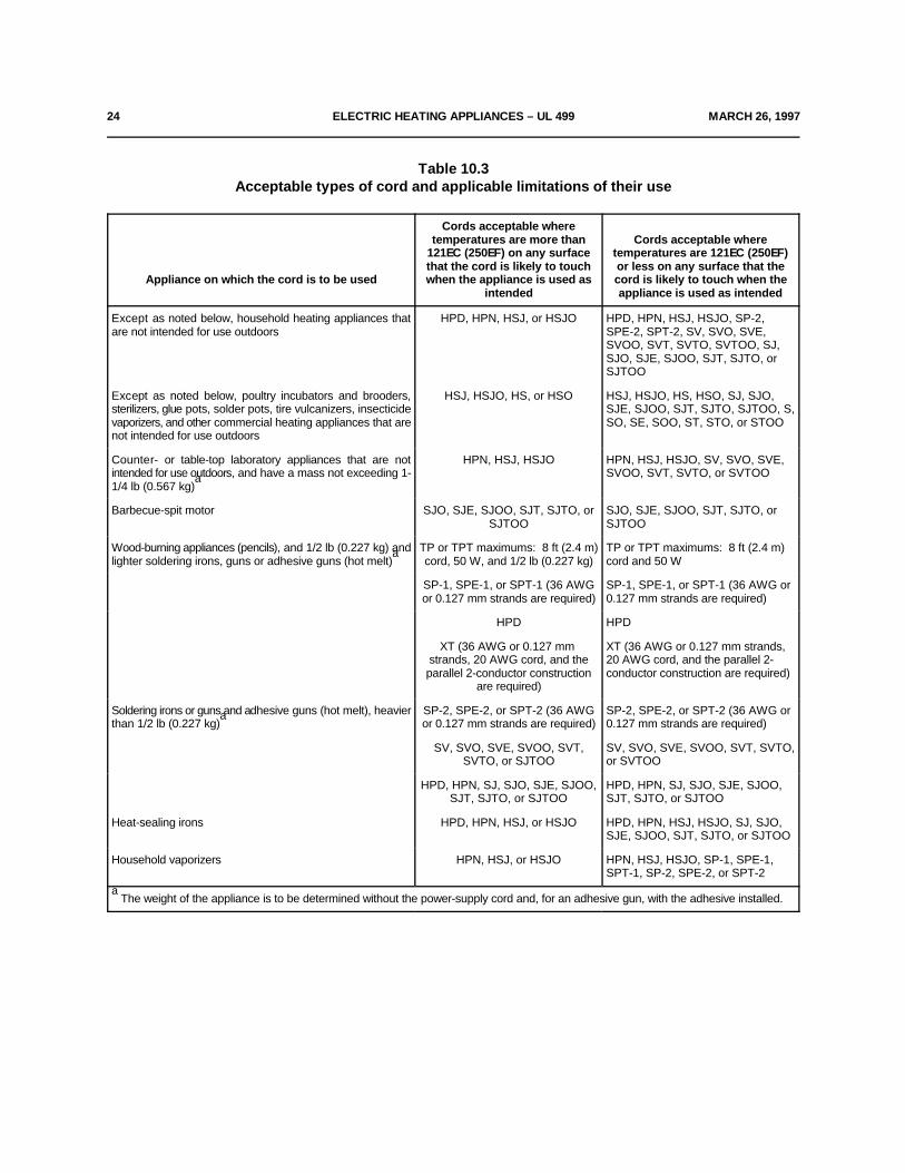
10.2.1.9 An attached power-supply cord and the cord in a detachable power-supply cord that is provided witha heating appliance shall be of a type indicated in Table 10.3, or shall have such properties that it will be at leastas serviceable for the particular application.

22B ELECTRIC HEATING APPLIANCES – UL 499 JULY 17,1998
No Text on This Page
MARCH 26, 1997 ELECTRIC HEATING APPLIANCES – UL 499 23
10.2.1.10 A vaporizer intended for use with glycol shall not employ thermoplastic-insulated flexible cord if theconstruction is such that the cord is likely to be exposed to the vapor.
10.2.1.11 The flexible cord provided with a stock tank de-icer, poultry water heater, or comparable heatingappliance intended or likely to be used out of doors shall be suitable for outdoor use and have a type letter suffixof "W-A".
10.2.1.12 Supplementary insulation, if employed on a flexible cord, shall not extend more than 1/2 inch (13mm) outside the product – unless provided with additional mechanical protection – shall not fray or unravel,and shall not affect adversely the means for providing strain relief.
10.2.1.13 An attachment plug having an Edison screw shell shall not be supplied with a cord-connectedproduct rated at more than 6 A or 660 W.
10.2.1.14 If the power source for a product is electrically separable from the product, both the power sourceand the product shall be marked in accordance with 45.25.
10.2.1.15 In addition to the requirement in 10.2.1.14, if the power source is not provided with a specialconnector, or if it is not permanently attached to the product, the power source shall comply with the applicablerequirements for that power equipment.
24 ELECTRIC HEATING APPLIANCES – UL 499 MARCH 26, 1997
Table 10.3Acceptable types of cord and applicable limitations of their use
Appliance on which the cord is to be used when the appliance is used as cord is likely to touch when the
Cords acceptable wheretemperatures are more than Cords acceptable where
121EC (250EF) on any surface temperatures are 121EC (250EF)that the cord is likely to touch or less on any surface that the
intended appliance is used as intended
Except as noted below, household heating appliances that HPD, HPN, HSJ, or HSJO HPD, HPN, HSJ, HSJO, SP-2,are not intended for use outdoors SPE-2, SPT-2, SV, SVO, SVE,
SVOO, SVT, SVTO, SVTOO, SJ,SJO, SJE, SJOO, SJT, SJTO, orSJTOO
Except as noted below, poultry incubators and brooders, HSJ, HSJO, HS, or HSO HSJ, HSJO, HS, HSO, SJ, SJO,sterilizers, glue pots, solder pots, tire vulcanizers, insecticide SJE, SJOO, SJT, SJTO, SJTOO, S,vaporizers, and other commercial heating appliances that are SO, SE, SOO, ST, STO, or STOOnot intended for use outdoors
Counter- or table-top laboratory appliances that are not HPN, HSJ, HSJO HPN, HSJ, HSJO, SV, SVO, SVE,intended for use outdoors, and have a mass not exceeding 1- SVOO, SVT, SVTO, or SVTOO1/4 lb (0.567 kg)
a
Barbecue-spit motor SJO, SJE, SJOO, SJT, SJTO, or SJO, SJE, SJOO, SJT, SJTO, orSJTOO SJTOO
Wood-burning appliances (pencils), and 1/2 lb (0.227 kg) and TP or TPT maximums: 8 ft (2.4 m) TP or TPT maximums: 8 ft (2.4 m)lighter soldering irons, guns or adhesive guns (hot melt) cord, 50 W, and 1/2 lb (0.227 kg) cord and 50 W
a
SP-1, SPE-1, or SPT-1 (36 AWG SP-1, SPE-1, or SPT-1 (36 AWG oror 0.127 mm strands are required) 0.127 mm strands are required)
HPD HPD
XT (36 AWG or 0.127 mm XT (36 AWG or 0.127 mm strands,strands, 20 AWG cord, and the 20 AWG cord, and the parallel 2-parallel 2-conductor construction conductor construction are required)
are required)
Soldering irons or guns and adhesive guns (hot melt), heavier SP-2, SPE-2, or SPT-2 (36 AWG SP-2, SPE-2, or SPT-2 (36 AWG orthan 1/2 lb (0.227 kg) or 0.127 mm strands are required) 0.127 mm strands are required)
a
SV, SVO, SVE, SVOO, SVT, SV, SVO, SVE, SVOO, SVT, SVTO,SVTO, or SJTOO or SVTOO
HPD, HPN, SJ, SJO, SJE, SJOO, HPD, HPN, SJ, SJO, SJE, SJOO,SJT, SJTO, or SJTOO SJT, SJTO, or SJTOO
Heat-sealing irons HPD, HPN, HSJ, or HSJO HPD, HPN, HSJ, HSJO, SJ, SJO,SJE, SJOO, SJT, SJTO, or SJTOO
Household vaporizers HPN, HSJ, or HSJO HPN, HSJ, HSJO, SP-1, SPE-1,SPT-1, SP-2, SPE-2, or SPT-2
The weight of the appliance is to be determined without the power-supply cord and, for an adhesive gun, with the adhesive installed.a
JULY 17, 1998 ELECTRIC HEATING APPLIANCES – UL 499 25
10.2.2 Strain relief
10.2.2.1 Strain relief shall be provided to restrict a mechanical stress on an attached power-supply cord frombeing transmitted to terminals, splices, or interior wiring.
10.2.2.2 If wood, pressed board, or other fibrous material is used to secure the strain-relief assembly, thefibrous material shall be secured to the product by a pin, setscrew, or other positive means.
10.2.2.3 Means shall be provided to restrict an attached power-supply cord from being pushed into theenclosure of a product through the cord-entry hole. To determine compliance, the supply cord shall be testedin accordance with the Push-Back Relief Test, Section 40A.
*Revised 10.2.2.3 effective July 16, 1999*
10.2.2.4 If a knot serves as strain relief in an attached power-supply cord, any surface with which the knot maycome in contact shall be free from projections, sharp edges, burrs, fins, and the like, that may cause abrasionof the insulation on the conductors.
10.2.3 Pin terminals
10.2.3.1 If a heating appliance is provided with pin terminals, the construction of the product shall be such thatlive parts will not be exposed to unintentional contact both during and after the placement of the plug on thepins, in the intended manner.
10.2.3.2 A pin guard is required, such that:
a) A straight edge placed in any position, across and in contact with edges of the plug opening withoutthe plug in place, cannot be made to contact any current-carrying pin.
b) With the plug aligned with the pins and the face of the plug in a plane located perpendicular to theend or ends of the farthest projecting current-carrying pin, the probe illustrated in Figure 6.4 should nottouch any current-carrying pin while the probe is inserted through any opening with the product in anyposition.
10.2.3.3 The plug used in 10.2.3.2(b) is to be the plug supplied with the product.
10.2.3.4 If a heating appliance employs three or more pin terminals designed for use with a plug that coversall the pins, the terminals shall be so spaced that they will not accommodate a flatiron or appliance plug or cordconnector. The plug which these pins will accommodate shall be acceptable for the particular application.
10.2.3.5 A pin terminal shall be securely mounted by means other than friction between surfaces, and shallnot shift in position.
10.2.3.6 The requirement in 10.2.3.5 is intended primarily to provide for the maintenance of spacings as givenin 25.1.1.1 and Tables 25.1 and 25.2 and to provide for the maintenance of proper spacings between pinterminals. Under this requirement, consideration is also to be given to the means for locking terminals inposition to maintain tightness.
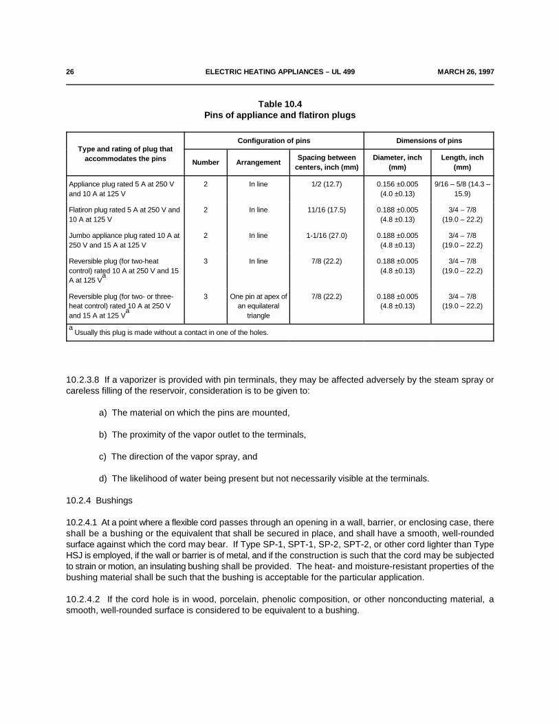
10.2.3.7 For a household-type heating appliance, the dimensions of pins and their center-to-center spacings– including the corresponding spacings of the female contacts of general-use plugs that these arrangementsof pins will accommodate are as indicated in Table 10.4.
26 ELECTRIC HEATING APPLIANCES – UL 499 MARCH 26, 1997
Table 10.4Pins of appliance and flatiron plugs
Type and rating of plug thataccommodates the pins
Configuration of pins Dimensions of pins
Number ArrangementSpacing between Diameter, inch Length, inch
centers, inch (mm) (mm) (mm)
Appliance plug rated 5 A at 250 V 2 In line 1/2 (12.7) 0.156 ±0.005 9/16 – 5/8 (14.3 –and 10 A at 125 V (4.0 ±0.13) 15.9)
Flatiron plug rated 5 A at 250 V and 2 In line 11/16 (17.5) 0.188 ±0.005 3/4 – 7/810 A at 125 V (4.8 ±0.13) (19.0 – 22.2)
Jumbo appliance plug rated 10 A at 2 In line 1-1/16 (27.0) 0.188 ±0.005 3/4 – 7/8250 V and 15 A at 125 V (4.8 ±0.13) (19.0 – 22.2)
Reversible plug (for two-heat 3 In line 7/8 (22.2) 0.188 ±0.005 3/4 – 7/8control) rated 10 A at 250 V and 15 (4.8 ±0.13) (19.0 – 22.2)A at 125 V
a
Reversible plug (for two- or three- 3 One pin at apex of 7/8 (22.2) 0.188 ±0.005 3/4 – 7/8heat control) rated 10 A at 250 V an equilateral (4.8 ±0.13) (19.0 – 22.2)and 15 A at 125 V triangle
a
Usually this plug is made without a contact in one of the holes.a
10.2.3.8 If a vaporizer is provided with pin terminals, they may be affected adversely by the steam spray orcareless filling of the reservoir, consideration is to be given to:
a) The material on which the pins are mounted,
b) The proximity of the vapor outlet to the terminals,
c) The direction of the vapor spray, and
d) The likelihood of water being present but not necessarily visible at the terminals.
10.2.4 Bushings
10.2.4.1 At a point where a flexible cord passes through an opening in a wall, barrier, or enclosing case, thereshall be a bushing or the equivalent that shall be secured in place, and shall have a smooth, well-roundedsurface against which the cord may bear. If Type SP-1, SPT-1, SP-2, SPT-2, or other cord lighter than TypeHSJ is employed, if the wall or barrier is of metal, and if the construction is such that the cord may be subjectedto strain or motion, an insulating bushing shall be provided. The heat- and moisture-resistant properties of thebushing material shall be such that the bushing is acceptable for the particular application.
10.2.4.2 If the cord hole is in wood, porcelain, phenolic composition, or other nonconducting material, asmooth, well-rounded surface is considered to be equivalent to a bushing.
MARCH 26, 1997 ELECTRIC HEATING APPLIANCES – UL 499 27
10.2.4.3 Ceramic materials and some molded compositions are acceptable generally for insulating bushings,but a separate bushing of wood, hot-molded shellac and tar composition, or rubber material (other than in amotor) is not acceptable. Vulcanized fiber may be employed if the bushing is not less than 3/64 inch (1.2 mm)thick and if it is so formed and secured in place that it will not be affected adversely by moist conditions.
10.2.4.4 A separate soft-rubber, neoprene, or polyvinyl chloride bushing may be employed in the frame of amotor or in the enclosure of a capacitor physically attached to a motor – but not elsewhere in a heatingappliance, except as indicated in 10.2.4.5 – provided that:
a) The bushing is not less than 3/64 inch (1.2 mm) thick, and
b) The bushing is so located that it will not be exposed to oil, grease, oily vapor, or other substancehaving a deleterious effect on the compound employed.
10.2.4.5 A bushing of any of the materials mentioned in 10.2.4.4 may be employed at any point in a productif used in conjunction with a type of cord for which an insulating bushing is not required, and if the edges of thehole in which the bushing is mounted are smooth and free from burrs, fins, and the like.
10.2.4.6 An insulated metal grommet is acceptable in place of an insulating bushing if the insulating materialused is not less than 1/32 inch (0.8 mm) thick, and completely fills the space between the grommet and themetal in which it is mounted.
11 Current-Carrying Parts
11.1 Each current-carrying part shall be made of metal that is acceptable for the particular application.
11.2 Current-carrying parts made of corrosion-resistant alloys, for example, stainless steel, are acceptableregardless of temperature. Current-carrying parts made of ordinary iron and steel are not acceptable unlessthey are rendered corrosion-resistant by a coating and, even then, they are acceptable only as follows:
a) Pin terminals.
b) Terminals and other parts of a motor and its governor (if any).
c) Parts whose normal operating temperature is higher than 100EC (212EF).
d) Parts of a component that the requirements referred to in 2.1 indicate as being acceptable withcoated iron and steel parts.
11.3 A heating appliance that is provided with a reservoir (intended to hold a liquid), shall have all live parts solocated or otherwise protected so that they will not be subject to wetting if the reservoir were to leak.
Exception: Live parts need not be so located or protected if the reservoir:
a) Is resistant to corrosion from the liquid intended for use in it, and
b) Complies with the applicable requirements in Resistance to Impact, Section 36.
28 ELECTRIC HEATING APPLIANCES – UL 499 MARCH 26, 1997
12 Internal Wiring
12.1 General
12.1.1 The internal wiring of a heating appliance shall consist of wires of a size and type or types that areacceptable for the particular application, when considered with respect to:
a) The temperature and voltage to which the wiring is likely to be subjected,
b) Its exposure to oil or grease, and
c) Other conditions of service to which it is likely to be subjected.
12.1.2 There is no temperature limit applicable to glass fiber, beads of inorganic material, or the equivalentemployed as conductor insulation.
12.1.3 Thermoplastic-insulated wire employed for the internal wiring of a heating appliance shall be standardbuilding wire, fixture wire, or appliance-wiring material acceptable for the particular application.
12.2 Protection of wiring
12.2.1 The wiring and connection between parts of a heating appliance shall be protected or enclosed, exceptthat a length of flexible cord may be employed for external connections, or for internal connections that maybe exposed during servicing, if flexibility of the wiring is essential. A bare conductor or a conductor with beadsfor insulation shall not be used outside an enclosure.
12.2.2 Internal wiring which is exposed through an opening in the enclosure of a heating appliance isconsidered to be protected as required in 12.2.1 if, when judged as if it were enamel-insulated wire, the wiringwould be acceptable according to 6.8 – 6.13. Internal wiring within an enclosure is acceptable if, even thoughit can be touched with the probe, it is so protected or guarded that it cannot be grasped or hooked in such amanner that it could be subjected to stress.
12.2.3 Internal terminals and wiring of a vaporizer may be adversely affected by the steam spray or carelessfilling of the reservoir. Accordingly, the items mentioned in 10.2.3.8 should be given consideration.
12.2.4 If the wiring of a heating appliance is so located that it may be in proximity to combustible material ormay be subjected to mechanical injury, it shall be armored cable or in rigid metal conduit, electrical metallictubing, metal raceway, or shall otherwise be protected.
12.2.5 Wires within an enclosure, compartment, raceway, or the like, shall be so located or protected thatdamage to conductor insulation cannot result from contact with any rough, sharp, or moving part.
12.2.6 A hole by means of which insulated wires pass through a sheet-metal wall within the overall enclosureof a heating appliance shall be provided with a smooth, well-rounded bushing or shall have smooth, well-rounded surfaces upon which the wires may bear, so as not to abrade the insulation. A flexible cord used forexternal interconnection as mentioned in 12.2.1 shall be provided with a strain relief and bushings inaccordance with 10.2.2.1 – 10.2.2.4 and 10.2.4.1 – 10.2.4.6 unless the construction is such that the cord willbe protected from stress or motion.
12.2.7 Insulated wires may be bunched and passed through a single opening in a metal wall within theenclosure of a heating appliance.

MARCH 26, 1997 ELECTRIC HEATING APPLIANCES – UL 499 30
12.3 Splices
12.3.1 All splices and connections shall be mechanically secure and shall provide good electrical contact. Asoldered connection shall be made mechanically secure before being soldered if breaking or loosening of theconnection may result in risk of fire or electric shock.
12.3.2 A splice shall be provided with insulation equivalent to that of the wires involved if permanence ofspacing between the splice and other metal parts of the product is not reliably maintained.
12.3.3 Insulation consisting of two layers of friction tape, two layers of thermoplastic tape, or of one layer offriction tape on top of one layer of rubber tape, is acceptable on a splice if the voltage involved is not more than250 V. In determining whether splice insulation consisting of coated fabric, thermoplastic, or other type of tubingis acceptable, consideration is to be given to such factors as its dielectric properties, heat-resistant andmoisture-resistant characteristics. Thermoplastic tape wrapped over a sharp edge is not acceptable.
12.3.4 Where stranded internal wiring is connected to a wire-binding screw, loose strands of wire shall notcontact any other uninsulated live part that is not always of the same polarity as the wire, and shall not contactany dead metal part. This may be accomplished by the use of pressure terminal connectors, soldering lugs,crimped eyelets, soldering all strands of the wire together, or other reliable means.
12.4 Separation of circuits
12.4.1 General
12.4.1.1 Unless provided with insulation rated for the highest voltage involved, insulated conductors of circuitsconnected to separate sources of supply shall be separated by barriers or segregated. Except as describedin 12.4.1.3, an insulated conductor of one circuit shall be separated or segregated from any uninsulated liveparts of a different circuit.
12.4.1.2 Segregation of insulated conductors may be accomplished by clamping, routing, or an equivalentmeans that provides permanent separation from insulated or uninsulated live parts of a different circuit.
12.4.1.3 Field-installed conductors of any circuit shall be segregated by barriers from:
a) Field-installation and factory-installed conductors connected to any other circuit, unless theconductors of both circuits are or will be insulated for the maximum voltage of either circuit, and
b) Uninsulated live parts of any other circuit of the product, and from any uninsulated live parts whoseshort-circuiting would result in a risk of fire or electric shock except that:
1) A construction in which field-installed conductors may make contact with wiring terminalsis acceptable provided that Type T, TF, or equivalent conductors are or will be installed, and
2) A construction in which field-installed conductors that do or may have insulation less thanthe types of wire mentioned in (1) may make contact with low-voltage wiring terminals (see12.4.2.1) is acceptable, provided that the short-circuiting of such terminals would not result ina risk of fire or electric shock.

31 ELECTRIC HEATING APPLIANCES – UL 499 MARCH 26, 1997
12.4.1.4 With respect to 12.4.1.3(a), if the intended uses of a product are such that in some applications abarrier is required, a removable barrier or one having opening for the passage of conductors may be employedprovided instructions for the use of the barrier are a permanent part of the product, and complete instructionsin conjunction with a wiring diagram may be acceptable instead of a barrier if, upon investigation, thecombination is found to be adequate.
12.4.1.5 Segregation of field-installation conductors from other field-installation conductors and fromuninsulated live parts of a product connected to different circuits may be accomplished by arranging the locationof the openings in the enclosure for the various conductors – with respect to the terminals or other uninsulatedlive parts – so that there is no likelihood of the intermingling of the conductors or parts of different circuits. Ifthe number of openings in the enclosure does not exceed the minimum required for the proper wiring of theproduct, and if each opening is located opposite a set of terminals, it is to be assumed – for the purpose ofdetermining whether the product complies with the requirement in 12.4.1.3 – that the conductors entering eachopening will be connected to the terminals opposite the opening. If more than the minimum number of openingsare provided, the possibility of conductors entering at points other than opposite the terminals to which they areintended to be connected and contacting insulated conductors or uninsulated current-carrying parts connectedto a different circuit is to be investigated. To determine whether the product complies with the requirement in12.4.1.3, it is to be wired as it would be in service, and in doing so, a reasonable amount of slack is to be leftin each conductor, within the enclosure, and no more than average care is to be exercised in stowing this slackin the wiring compartment.
12.4.2 Low-voltage circuit
12.4.2.1 A low-voltage circuit is one involving a potential of not more than 30 V (42.4 volts peak) and suppliedby a primary battery, by a standard Class 2 transformer, or by an impedance which, as a unit, complies withall of the performance requirements for a Class 2 transformer.
12.4.2.2 A circuit derived from a source of supply classified in 12.4.3.1 as a line-voltage circuit, by connectingresistance in series with the supply circuit as a means of limiting the voltage and current, is not considered tobe a low-voltage circuit as described in 12.4.2.1.
12.4.3 Line-voltage circuit
12.4.3.1 A line-voltage circuit is one involving a potential of not more than 600 V and having circuitcharacteristics in excess of those of a low-voltage circuit.
12.4.4 Barriers
12.4.4.1 If a barrier is used to provide separation between the wiring of different circuits, it shall be of metal orof insulating material, of adequate mechanical strength if exposed or otherwise likely to be subjected tomechanical damage, and reliably held in place. Unclosed openings in a barrier for the passage of conductorsshall not be larger in diameter than 1/4 inch (6.4 mm) and shall not exceed in number, on the basis of oneopening per conductor, the number of wires that will need to pass through the barrier. The closure for any otheropening shall present a smooth surface wherever an insulated wire may be in contact with it, and the area ofany such opening, with the closure removed, shall not be larger than required for the passage of the necessarywires.
12.4.4.2 A metal barrier shall have a thickness at least as great as the minimum acceptable thickness of theenclosure metal. A barrier of insulating material shall not be less than 0.028 inch (0.71 mm) thick and shallbe of greater thickness if its deformation may be readily accomplished so as to defeat its purpose.

MARCH 26, 1997 ELECTRIC HEATING APPLIANCES – UL 499 32
13 Heating Elements
13.1 A heating element shall be supported in an acceptable manner. It shall be protected against mechanicaldamage and contact with outside objects.
13.2 In determining whether a heating element is acceptably supported, consideration is to be given to sagging,loosening, and other adverse conditions of the element resulting from continuous heating.
13.3 An open-wire element – that is, uninsulated resistance wire – may be used in heating appliances providedit is enclosed or protected by barriers or covers that require tools for removal, and it complies with theaccessibility of live parts requirements outlined in 6.13 – 6.17.
13.4 A heating appliance in which the heating element is constructed for use only in an air blast shall be sowired or controlled that the element can be operated only while under the cooling effect of the blast. A productin which the cooling effect of the motion of a part is necessary to limit temperatures shall be so wired orcontrolled that the element cannot be operated without such motion.
14 Electrical Insulation
14.1 Insulating washers, bushings, and the like, that are integral parts of a heating appliance and bases orsupports for the mounting of current-carrying parts shall be of a moisture-resistant material that will not bedamaged by the temperatures to which they will be subjected under conditions of actual use. Molded partsshall be so constructed that they will have the mechanical strength and rigidity necessary to withstand thestresses of actual service.
14.2 Insulating material employed in a heating appliance is to be judged with respect to its acceptability for theparticular application. Materials, such as mica, some molded compounds, and certain refractory materials areusually acceptable for use as the sole support of live parts, and some other materials that are not acceptablefor general use, such as magnesium oxide, may be acceptable if used in conjunction with other moreacceptable insulating materials or if so located and protected such that it is not subject to mechanical damageand the absorption of moisture is minimized. When it is necessary to investigate a material to determinewhether it is acceptable, consideration is to be given to its mechanical strength, dielectric properties, insulationresistance, heat-resistant qualities, the degree to which it is enclosed or protected, and any other featureshaving a bearing on the risk of fire or electric shock involved, in conjunction with conditions of actual service.All of these factors are considered with respect to thermal aging.
14.3 In the mounting or supporting of small, fragile insulating parts, screws or other fastenings should not betight enough to cause cracking or breaking of these parts with expansion and contraction. Generally, such partsshould be slightly loose.
15 Thermal Insulation
15.1 Thermal insulation, if employed, shall be of such a nature and so located and mounted or supported thatit will not be affected by any intended operation of the product. See 32.1.22.
15.2 Combustible or electrically conductive thermal insulation shall not make contact with uninsulated live partsof a heating appliance.
15.3 Some types of mineral-wool thermal insulation contain conductive impurities in the form of slag, whichmake its use unacceptable if in contact with uninsulated live parts. See 33.1.
33 ELECTRIC HEATING APPLIANCES – UL 499 MARCH 26, 1997
16 Motors
16.1 A motor shall be acceptable for the particular application, and shall be capable of handling its maximumintended load without risk of fire, electric shock, or injury to persons.
16.2 A motor winding shall resist the absorption of moisture and shall be formed and assembled in aworkmanlike manner.
16.3 With reference to the requirement in 16.2, enameled wire is not required to be additionally treated, butfiber slot liners, cloth coil wrap, and similar moisture-absorptive materials should be provided with impregnationor otherwise treated.
17 Overcurrent Protection of Conductors and Heating Elements
17.1 Except as noted in 17.2 and 17.3, each bus bar and insulated wire, including those in heater, motor, andcontrol circuits, in a heating appliance rated at more than 40 A shall be protected by an overcurrent protectivedevice provided as a part of the product. If the product is intended for connection to more than one branchcircuit, each section of the product intended for connection to a different branch circuit is to be consideredindividually in applying the foregoing requirement. The rating of the overcurrent protective device shall be inaccordance with Table 17.1.
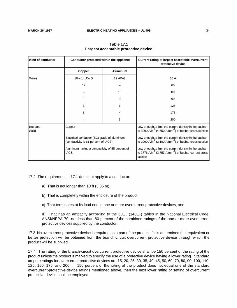
MARCH 26, 1997 ELECTRIC HEATING APPLIANCES – UL 499 34
Table 17.1Largest acceptable protective device
Kind of conductor Conductor protected within the appliance Current rating of largest acceptable overcurrentprotective device
Copper Aluminum
Wires 18 – 14 AWG 12 AWG 50 A
12 – 60
– 10 80
10 8 90
8 6 125
6 4 175
4 3 200
Busbars Copper Low enough to limit the current density in the busbarSolid to 3000 A/in (4.650 A/mm ) of busbar cross section
2 2
Electrical-conductor (EC) grade of aluminum Low enough to limit the current density in the busbar(conductivity is 61 percent of IACS) to 2000 A/in (3.100 A/mm ) of busbar cross section
2 2
Aluminum having a conductivity of 55 percent of Low enough to limit the current density in the busbarIACS to 1776 A/in (2.753 A/mm ) of busbar current cross
2 2
section
17.2 The requirement in 17.1 does not apply to a conductor:
a) That is not longer than 10 ft (3.05 m),
b) That is completely within the enclosure of the product,
c) That terminates at its load end in one or more overcurrent protective devices, and
d) That has an ampacity according to the 60EC (140EF) tables in the National Electrical Code,ANSI/NFPA 70, not less than 80 percent of the combined ratings of the one or more overcurrentprotective devices supplied by the conductor.
17.3 No overcurrent protective device is required as a part of the product if it is determined that equivalent orbetter protection will be obtained from the branch-circuit overcurrent protective device through which theproduct will be supplied.
17.4 The rating of the branch-circuit overcurrent protective device shall be 150 percent of the rating of theproduct unless the product is marked to specify the use of a protective device having a lower rating. Standardampere ratings for overcurrent protective devices are 15, 20, 25, 30, 35, 40, 45, 50, 60, 70, 80, 90, 100, 110,125, 150, 175, and 200. If 150 percent of the rating of the product does not equal one of the standardovercurrent-protective-device ratings mentioned above, then the next lower rating or setting of overcurrentprotective device shall be employed.

36 ELECTRIC HEATING APPLIANCES – UL 499 MARCH 26, 1997
17.5 The overcurrent protection mentioned in 17.1 – 17.4, 17.6 and 17.7 shall be of a type intended for branch-circuit protection. A fuse used for this purpose shall be a Class CC, G, H, J, K, R, or T cartridge fuse or a plugfuse.
17.6 A product that employs resistance-type heating elements and is rated at more than 48 A shall have theheating elements subdivided. Each subdivided load shall not exceed 48 A and shall be protected at not morethan 60 A.
Exception No. 1: Open coil or exposed sheathed-coil types of surface elements in commercial-type heatingappliances shall be protected by overcurrent protective devices at not more than 50 A.
Exception No. 2: Infrared lamp commercial and industrial heating appliances shall have overcurrent protectionnot exceeding 50 A.
17.7 The overcurrent protective devices required in 17.6 shall be provided as an integral part of the productor shall be provided by the product manufacturer as a separate assembly, for independent mounting, for usewith the product. See 45.26.
18 Motor-Running Overload Protection
18.1 The following heating appliances in which a 1-hp or smaller motor is used shall incorporate thermal oroverload protection so that the motor shall not attain excessively high temperatures under any operatingconditions:
a) A remotely or automatically controlled product.
b) A permanently connected, continuous-duty, manually started product.
An impedance-protected motor is not required to have additional thermal or overload protection.
18.2 A heating appliance intended to be automatically or remotely controlled and employing a motor rated atmore than 1 hp shall incorporate thermal or overcurrent protection.
18.3 Fuses shall not be used in motor-overload-protective devices unless the motor is protected by the largestsize of fuse that can be inserted in the fuseholder.
19 Motor and Power-Transformer Short-Circuit and Ground-Fault Protection
19.1 A motor or power transformer in a heating appliance rated at more than 16 A shall be protected againstshort circuits and grounding by an overcurrent device having a maximum ampere rating in accordance with theNational Electrical Code, ANSI/NFPA 70. Such overcurrent protection shall be provided as a part of the heatingappliance unless it can be determined in accordance with 17.3 that equivalent overcurrent protection would beincorporated as the branch-circuit protective device.
19.2 The overcurrent protection mentioned in 19.1 shall be of a type indicated as being acceptable for branch-circuit protection.
MARCH 26, 1997 ELECTRIC HEATING APPLIANCES – UL 499 37
20 General (Short-Circuit and Ground-Fault) Overcurrent Protection
20.1 Overcurrent protection at not more than 20 A shall be provided by means of a circuit breaker or fuse, asa part of a heating appliance, for each general-use receptacle circuit and each lampholder circuit independentof a heating element, included in the product, unless the product would be properly connected to a branchcircuit rated at 20 A or less.
20.2 The overcurrent protection mentioned in 20.1 shall be of a type indicated as being acceptable for branch-circuit protection.
20.3 A fuseholder or circuit breaker provided as a part of a heating appliance shall not be accessible withoutopening a door or cover. However, the operating handle of a circuit breaker, and a removable end cap of afuseholder, except on a household product, see 20.4, may project outside of the enclosure. A fuseholder shallbe so installed that no uninsulated live parts other than the screw shell or clips of the fuseholder are exposedto contact by a person removing or replacing a fuse. If the fuseholder is intended to be accessible only toservice personnel, uninsulated live parts other than the screw shell or clips may be exposed if they are guarded,or the fuseholder is so located such that these live parts shall not be subjected to unintentional contact.
20.4 A removable end cap of a fuseholder in a product intended for household use shall not be accessiblefrom the outside of the product.
21 Thermal Cutoffs
21.1 If a heating appliance is provided with a thermal cutoff, it shall be secured in place and shall be so locatedthat it will be accessible for replacement without damaging other connections or internal wiring. See 45.6.
21.2 If a heating appliance is provided with a thermal cutoff, it shall be capable of opening the circuit in theintended manner without causing the short-circuiting of live parts and without causing live parts to becomegrounded to the enclosure when the product is connected to a circuit of voltage in accordance with 32.1.13,and operated in a normal position to cause abnormal heating.
21.3 To determine whether a thermal cutoff complies with the requirement in 21.2, the product is to beoperated with separate cutoffs five times as described above while any other thermally operated control devicesin the product are short-circuited. Each cutoff is required to perform acceptably. During the test, the enclosureis to be connected through a 3-A fuse to a supply conductor not containing the cutoff.
22 Lampholders
22.1 If a heating appliance intended for permanent connection to the power supply or a heating applianceequipped with a polarized attachment plug is intended to be connected to the identified (grounded) conductorof a power-supply circuit, a lampholder supplied as a part of the product shall be so wired that the screw shellis connected to the identified conductor.
22.2 Except as noted in 22.3, a lampholder shall be so constructed and installed that uninsulated live partsother than the screw shell will not be exposed to contact by persons removing or replacing lamps.
22.3 The requirement in 22.2 does not apply if, in order to remove or replace a lamp, it is necessary todismantle the product by means of tools.
38 ELECTRIC HEATING APPLIANCES – UL 499 MARCH 26, 1997
22.4 A medium-base lampholder or screw-shell receptacle shall not be used as a holder for a heating elementrated at more than 6 A or 660 W, except that a screw shell with a left-handed thread may be used with aheating element rated at not more than 10 A.
22.5 Except as noted in 22.6, a screw-shell lampholder for an infrared lamp shall be of the unswitched,medium-base type and shall be used with a 300-W or smaller lamp.
22.6 A lamp-and-lampholder combination need not comply with the requirement in 22.5 if no unacceptabletemperature is produced on any of the components in the normal–temperature test, and if the switchingmechanism of a switched lampholder is capable of performing acceptably without undue burning, pitting, andthe like.
22.7 A female screwshell used as a holder for a heating element shall be of copper or of a copper-base alloyand shall be plated with nickel or equivalent oxidation-resistant metal.
Exception: Aluminum (plated or unplated), unplated copper, or unplated copper alloy may be used providedthe temperature rise does not exceed 175EC (315EF), based upon a room ambient temperature of 25EC (77EF),as measured with the product operating under the most adverse conditions of normal operation until thermalequilibrium is attained. All temperature regulating controls, if provided, shall be set at the maximum setting.Unplated aluminum shall only be used in equipment intended for indoor dry locations.
23 Switches
23.1 A switch or other control device provided as a part of a heating appliance shall be of a type intended forthe particular application and shall have a current and voltage rating not less than that of the circuit (load) thatit controls.
23.2 A switch employed on a heating appliance shall be so located or protected that it will not be subjectedto mechanical damage during use.
23.3 It is recommended that all switches be of an indicating type.
23.4 A switch on a cord-connected heating appliance incorporating an open-wire heating element constructionshall be of such a type and so connected that it will disconnect the element or elements that it controls fromall conductors of the supply circuit.
23.5 The requirement in 23.4 applies to a switch in the off position or any other setting in which the elementis not heated, and also to a through-cord switch or a plug in which a switch is incorporated in an attached ordetachable power-supply cord that is provided with such a heating appliance.
23.6 A switch or other device controlling one or more elements of a heating appliance intended for permanentconnection to the power supply shall be so arranged that the opening of the switch will disconnect all of theungrounded conductors of the supply circuit, unless there will be no live parts exposed to unintentional contactwhen the switch is open or unless the fact that such parts are alive is definitely apparent.
23.7 A switch or other means of control intended to provide for the use of a limited number of elements at onetime shall be so located or of such a type that the user cannot change the connections to energize moreelements than intended.

MARCH 26, 1997 ELECTRIC HEATING APPLIANCES – UL 499 39
23.8 A switch controlling a lampholder shall be acceptable for use with tungsten-filament lamps.
23.9 Except as noted in 23.10, a switch shall not be incorporated in a wooden handle or in other combustiblematerial unless enclosed in metal or insulating material.
23.10 In a small, low-wattage product such as a wood burning pencil, a switch may be acceptable in a woodenhandle.
23.11 If a heating appliance that is intended for connection to the supply circuit by means of flexible cord andan attachment plug employs a motor rated at more than 1/3 hp, a manually operated motor controller shall beprovided in the product.
23.12 A manually operated, line-connected, single pole switch, or other control device, intended for applianceon-off operation shall be connected to the ungrounded conductor of the power-supply cord. Table 10.2specifies the polarity identification of the power-supply cord conductors.
24 Automatic Controls and Control Circuits
24.1 A control circuit shall comply with the requirements in 12.4.1.1 – 12.4.2.2.
24.2 The operation of an auxiliary control device in a heating appliance shall disconnect the element orelements that it controls from all ungrounded conductors of the supply circuit, unless there will be no live partsexposed to unintentional contact when the auxiliary control device is open or unless the fact that such parts arealive is apparent.
24.3 An auxiliary control is considered to be one that is intended primarily for time, temperature or pressureregulation, and the like, under conditions of intended operation, and not for protection against overload orexcessive temperature conditions resulting from abnormal operation.
24.4 A device intended to reduce the risk of fire or electric shock shall be operative whenever the product isconnected to its power supply. Except for the inherent thermal protector of a motor, the control of a productintended to be permanently connected electrically that has exposed live parts shall disconnect the element orelements it controls from all ungrounded conductors of the supply circuit. The operation of such a control shallcomply with the requirements in 24.2. A controlled contactor shall comply with the endurance requirement fora limiting control if it is a part of the limiting-control circuit.
24.5 A control device shall not be constructed to deliberately overload the branch-circuit protective device asa means of disconnecting the product from the supply.
24.6 A contactor or similar device, such as a silicon controlled rectifier, required for use with a limit control shallbe provided by the manufacturer of the product, but need not be mounted on the product. See 45.26.
24.7 The terminals of a device mentioned in 24.4 within the enclosure of a heating appliance shall be solocated or further enclosed that they will be protected against unintentional short circuiting and damage.
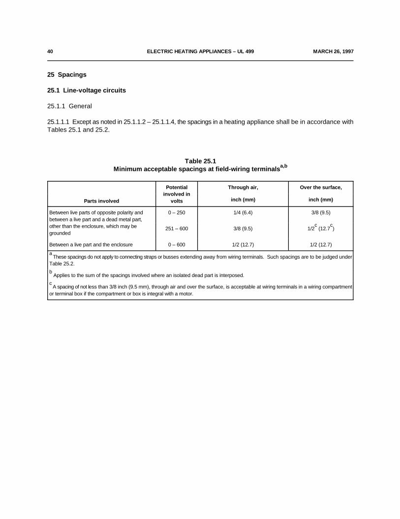
40 ELECTRIC HEATING APPLIANCES – UL 499 MARCH 26, 1997
25 Spacings
25.1 Line-voltage circuits
25.1.1 General
25.1.1.1 Except as noted in 25.1.1.2 – 25.1.1.4, the spacings in a heating appliance shall be in accordance withTables 25.1 and 25.2.
Table 25.1Minimum acceptable spacings at field-wiring terminalsa,b
Parts involved volts
Potential Through air, Over the surface,involved in
inch (mm) inch (mm)
Between live parts of opposite polarity and 0 – 250 1/4 (6.4) 3/8 (9.5)between a live part and a dead metal part,other than the enclosure, which may begrounded
251 – 600 3/8 (9.5) 1/2 (12.7 )c c
Between a live part and the enclosure 0 – 600 1/2 (12.7) 1/2 (12.7)
These spacings do not apply to connecting straps or busses extending away from wiring terminals. Such spacings are to be judged undera
Table 25.2.
Applies to the sum of the spacings involved where an isolated dead part is interposed.b
A spacing of not less than 3/8 inch (9.5 mm), through air and over the surface, is acceptable at wiring terminals in a wiring compartmentc
or terminal box if the compartment or box is integral with a motor.
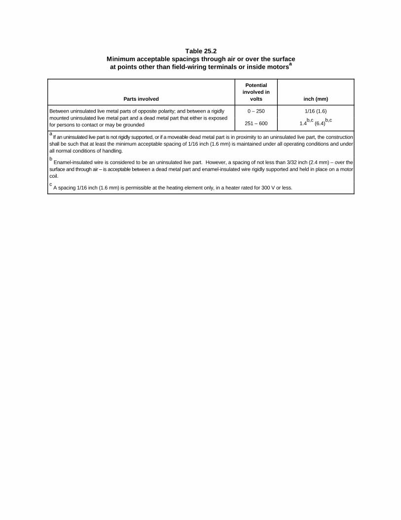
Table 25.2Minimum acceptable spacings through air or over the surfaceat points other than field-wiring terminals or inside motorsa
Parts involved volts inch (mm)
Potentialinvolved in
Between uninsulated live metal parts of opposite polarity; and between a rigidly 0 – 250 1/16 (1.6)mounted uninsulated live metal part and a dead metal part that either is exposedfor persons to contact or may be grounded 251 – 600 1.4 (6.4)
b,c b,c
If an uninsulated live part is not rigidly supported, or if a moveable dead metal part is in proximity to an uninsulated live part, the constructiona
shall be such that at least the minimum acceptable spacing of 1/16 inch (1.6 mm) is maintained under all operating conditions and underall normal conditions of handling.
Enamel-insulated wire is considered to be an uninsulated live part. However, a spacing of not less than 3/32 inch (2.4 mm) – over theb
surface and through air – is acceptable between a dead metal part and enamel-insulated wire rigidly supported and held in place on a motorcoil.
A spacing 1/16 inch (1.6 mm) is permissible at the heating element only, in a heater rated for 300 V or less.c
MARCH 26, 1997 ELECTRIC HEATING APPLIANCES – UL 499 42
25.1.1.2 The spacings specified in Tables 25.1 and 25.2 do not apply to the inherent spacings of a componentpart of a heater; such spacings are judged under the requirements for the component in question.
25.1.1.3 The spacings within a motor shall comply with the requirements in the Standard for Electric Motors,UL 1004.
25.1.1.4 At closed-in points only, such as the screw-and-washer construction of an insulated terminal mountedin metal, a spacing of 3/64 inch (1.2 mm) is acceptable in a product rated at 250 V or less. Within a thermostat,except at contacts, the spacings between uninsulated live parts on opposite sides of the contacts are to be notless than 1/32 inch (0.8 mm) through air and 3/64 inch (1.2 mm) over the surface of insulating material, andthe construction is to be such that the spacings will be maintained permanently.
25.1.2 Barriers
25.1.2.1 Except as noted in 25.1.2.2, an insulating liner or barrier of fiber or similar material employed wherespacings would otherwise be unacceptable shall not be less than 1/32 inch (0.8 mm) thick and shall be solocated or of such material that it cannot be affected by arcing, except that fiber not less than 1/64 inch (0.4mm) thick may be used in conjunction with an air spacing of not less than 50 percent of the spacing requiredfor air alone.
25.1.2.2 Insulating material having a thickness less than specified in 25.1.2.1 may be used if it is equivalent inappropriate properties.
25.1.2.3 Unless protected from mechanical abuse during assembly and intended functioning of a product, abarrier of mica shall be 0.010 inch (0.25 mm) or thicker.
25.2 Low-voltage circuits
25.2.1 Limiting controls
25.2.1.1 The spacings in a low-voltage limiting control shall comply with the requirements in 25.1.1.1 – 25.1.2.3and Tables 25.1 and 25.2.
25.2.2 Other than limiting controls
25.2.2.1 The spacing between uninsulated live parts of opposite polarity and between such parts and deadmetal that may be grounded in service is not specified for parts of circuits that are classified as low-voltage in12.4.2.1.
26 Grounding
26.1 In a heating appliance intended for permanent connection to the power supply by a metal-enclosed wiringsystem, such as rigid metal conduit or armored cable, all exposed dead metal parts and all dead metal partsinside the enclosure that are exposed to contact during any servicing operation – including maintenance andrepair – and that are likely to become energized shall be conductively connected to the point at which the cablearmor, conduit, and the like, is attached to the product.

43 ELECTRIC HEATING APPLIANCES – UL 499 MARCH 26, 1997
26.2 In a product intended for permanent connection to the power supply by means other than a metal-enclosed wiring system, such as nonmetallic-sheathed cable:
a) An equipment-grounding terminal or lead shall be provided (see 10.1.2.13 and 10.1.2.14), and
b) All exposed dead metal parts and all dead metal parts inside the enclosure that are exposed tocontact during any servicing operation – including maintenance and repair – that are likely to becomeenergized shall be conductively connected to such terminal or lead.
26.3 On a portable product where grounding is required or provided, the power-supply cord or cord set shallinclude a grounding conductor that shall be:
a) Green with or without one or more yellow stripes,
b) Connected to the grounding blade of an attachment plug of a grounding type, and
c) Connected to the enclosure of the product by means of a screw not likely to be removed duringservicing, or by other equivalent means. Solder alone is not acceptable for making this connection.
26.4 If any accessible dead metal part of a product is grounded, all accessible dead metal parts that are likelyto become energized, including those exposed during any servicing operation – including maintenance andrepair – shall be grounded.
26.5 A cord-connected heating appliance constructed for operation on a circuit involving a potential of morethan 150 V to ground shall have provision for grounding, in accordance with 26.3, of all exposed dead metalparts, and all dead metal parts exposed during any servicing operation – including maintenance and repair –that are likely to be energized.
26.6 A cord-connected stock-tank de-icer, poultry-water heater, branding iron, dehorning iron, poultrycauterizer, charcoal ignitor, incubator, and brooder, or similar device intended for outdoor use, and arefrigerator defroster and heat gun shall either:
a) Be double insulated, or
b) Have provision for grounding dead metal parts in the form of a grounding conductor in the cord anda grounding type of attachment plug, in accordance with 26.3 (see also 45.10).
Grounding shall not be used if the product is marked as being provided with double insulation.
26.7 A cord-connected, 2-wire heating appliance intended to operate at a nominal potential of 240 V – andsimilarly any other potential within the 220 – 250 V range – is considered as requiring provision for groundingin accordance with 26.3 unless the marked rating on the product is 120/240 V or unless the product is otherwisemarked to indicate that it is to be connected only to a 120/240-V circuit with a grounded neutral.
MARCH 26, 1997 ELECTRIC HEATING APPLIANCES – UL 499 44
27 Pressure Vessels and Parts Subject to Pressure
27.1 Except as noted in 27.2, a pressure vessel having an inside diameter of more than 6 inches (152 mm)and subject to a pressure of more than 15 lbf/in (103 kN/m ) shall be certified by the National Board of Boiler2 2
and Pressure-Vessel Inspectors and marked in accordance with the appropriate boiler and pressure vesselcode symbol ("H", "M", "S", or "U") of the American Society of Mechanical Engineers (ASME) for a workingpressure no less than the pressure determined by applying 27.3.
27.2 If a pressure vessel, because of its application, is not covered under the inspection procedures of theASME code, it shall be so designed and constructed that it will comply with the requirements in 27.3.
27.3 Except as noted in 27.4 and 27.5, a part that is subject to air or vapor pressure, including the vaporpressure in a vessel containing only a superheated fluid, during normal or abnormal operation shall withstandwithout bursting or leaking a pressure equal to the highest of the following that is applicable:
a) Five times the pressure corresponding to the maximum setting of a pressure-reducing valveprovided as part of the assembly, but not more than five times the marked maximum supply pressurefrom an external source and not more than five times the pressure setting of a pressure-relief deviceprovided as part of the assembly.
b) Five times the marked maximum supply pressure from an external source, except as provided in(a).
c) Five times the pressure setting of a pressure-relief device provided as part of the assembly.
d) Five times the maximum pressure that can be developed by an air compressor that is part of theassembly, unless the pressure is limited by a pressure-relief device in accordance with (a).
e) Five times the working pressure marked on the part.
27.4 A test need not be performed to determine whether a part complies with the requirement in 27.3 if studyand analysis of the material and dimensions indicate that the part has the strength acceptable for theapplication – for example, copper or steel pipe of standard size and provided with standard fittings might beconsidered to have the strength for the application.
27.5 A pressure vessel bearing the ASME code inspection symbol ("H", "M", "S", or "U") is considered tocomply with the requirement in 27.3 if the vessel is marked with a value of working pressure not less than thatto which it is subject during normal or abnormal operation.
27.6 If a test is necessary to determine whether a part complies with the requirement in 27.3, two samples ofthe part are to be subjected to a hydrostatic-pressure test. Each sample is to be so filled with water as toexclude air and is to be connected to a hydraulic pump. The pressure is to be raised gradually to the specifiedtest value and is to be held at that value for 1 minute. The results are not acceptable if either sample burstsor leaks, except as indicated in 27.7.
27.7 Leakage at a gasket during the hydrostatic-pressure test is acceptable if it does not occur at a pressure40 percent or less of the required test value.
45 ELECTRIC HEATING APPLIANCES – UL 499 MARCH 26, 1997
27.8 A means for relieving pressure shall be provided for all parts in which pressure might be generated in theevent of fire.
27.9 Pressure-relief devices (see 27.15), fusible plugs, soldered joints, nonmetallic tubing, or other pressure-relief means or the equivalent may be employed to comply with the requirements in 27.8.
27.10 There shall be no shut-off value between the pressure-relief means and the parts that it is intended toprotect.
27.11 A vessel having an inside diameter of more than 3.0 inches (76.2 mm) and subject to air or steampressure generated or stored within the product shall be protected by a pressure-relief device.
27.12 The start-to-discharge pressure setting of the pressure-relief device shall not be higher than the workingpressure marked on the vessel. The discharge rate of the device shall be capable of relieving the pressure.
27.13 A pressure-relief device shall comply with all four of the following:
a) It shall be connected as close as possible to the pressure vessel or parts of the system that it isintended to protect.
b) It shall be so installed that it is readily accessible for inspection and repair and cannot be readilyrendered inoperative.
c) It shall have its discharge opening so located and directed that the risk of scalding is reduced to aminimum.
d) It shall have its discharge opening so located and directed that operation of the device will notdeposit moisture on bare live parts or on insulation or components affected by moisture.
27.14 A pressure-relief device having an adjustable setting is judged on the basis of its maximum setting unlessthe adjusting means is sealed at a lower setting.
27.15 A pressure-relief device is considered to be a pressure-actuated valve or rupture member constructedto relieve excessive pressures automatically.
27.16 Where a pressure-relief device is required, the control responsible for limiting the pressure in the vesselshall be capable of performing under rated load for 100,000 cycles of operation and the control shall limit thepressure so that it does not exceed 90 percent of the relief device setting under any condition of intendedoperation.
28 Protection Against Injury to Persons
28.1 Materials employed in the construction of the product that reduce the risk of injury to persons shall beacceptable for the particular use. See 6.1 and 6.5.
28.2 All heating appliances, or any items furnished with the product, shall have no sharp edges, burrs, points,or spikes inside or outside the product, that may present a risk of injury to persons during use, includingcleaning operations.
JULY 17, 1998 ELECTRIC HEATING APPLIANCES – UL 499 46
28.3 The temperature of a surface that is likely to be contacted by the user – other than a heating functionsurface and an adjacent surface known to be hot because of its proximity to a heating function surface – shallnot be more than the value specified in Table 32.2 when measured in accordance with the applicablerequirements in the Normal Temperature Test, Section 32.
Exception: Accessible surfaces, other than handles or knobs, may have temperatures that exceed thoseshown in Table 32.2 if marked in accordance with 45.35.
PERFORMANCE
29 General
29.1 The performance of a heating appliance shall be investigated by subjecting the requisite number ofspecimens to all the applicable tests as described in Sections 30 – 41. Insofar as practicable, the tests shallbe conducted in the order in which they are presented here. Specimens employed for leakage-current testsshall be first tested for leakage prior to employing the specimens for other tests.
*29.1 revised July 17, 1998*
30 Power Input Test
30.1 The power input to a heating appliance shall not be more than 105 percent of its marked rating.
30.2 To determine whether a heating appliance complies with the requirement in 30.1, the power input is tobe measured with the product at normal operating temperature under full-load conditions and while connectedto a supply circuit adjusted to be the highest of the following:
a) The marked voltage rating, or
b) The highest voltage of the applicable range of voltages specified in 44.1 if the marked voltage iswithin one of the voltage ranges indicated in 44.1.
If a product employs a nonmetallic element, such as carbon, the power input is to be determined for a newelement.
30.3 In a test to determine whether a heating appliance of the immersed-electrode type complies with therequirement in 30.1, the hard-water solution described in 31.10 is to be used.
31 Leakage Current
31.1 The leakage current of a cord-connected product rated for a nominal 120-, 208-, or 240-V supply whentested in accordance with 31.3 – 31.8 shall not be more than:
a) 0.5 mA for an ungrounded (2-wire) product,
b) 0.5 mA for a grounded (3-wire) portable product, and
c) 0.75 mA for a grounded (3-wire) product intended to be fastened in place or located in a dedicatedspace and employing a standard attachment plug rated 20 A or less.
Exception: During heat-up and cool-down, as defined in Table 1 of Leakage Current for Appliances, ANSIC101.1-1992, the leakage current of a product employing a sheath-type heating element, when measured inaccordance with 31.3 – 31.8, may exceed 0.5 mA or 0.75 mA, as applicable, but shall not exceed 2.5 mA duringa period of 5 minutes beginning with the moment the leakage current exceeds 0.5 mA or 0.75 mA, asapplicable. At the end of the 5 minute period, the leakage current shall not be more than 0.5 mA or 0.75 mA,as applicable.
47 ELECTRIC HEATING APPLIANCES – UL 499 MARCH 26, 1997
31.2 Leakage current refers to all currents, including capacitively coupled currents, that may be conveyedbetween exposed conductive surfaces of a product and ground or other exposed conductive surfaces of aproduct.
31.3 All exposed conductive surfaces are to be tested for leakage currents. The leakage currents from thesesurfaces are to be measured to the grounded supply conductor individually as well as collectively wheresimultaneously accessible and from one surface to another where simultaneously accessible. Parts areconsidered to be exposed surfaces unless guarded by an enclosure considered acceptable for protectionagainst a risk of electric shock as defined in 6.1 – 6.17. Surfaces are considered to be simultaneouslyaccessible when they can be contacted by one or both hands of a person at the same time. Thesemeasurements do not apply to terminals operating at voltage levels that do not involve a risk of electric shock.
31.4 If a conductive surface other than metal is used for the enclosure or part of the enclosure, the leakagecurrent is to be measured using a metal foil with an area of 10 by 20 cm in contact with surface. Where thesurface is less than 10 by 20 cm, the metal foil is to be the same size as the surface. The metal foil is not toremain in place long enough to affect the temperature of the product.
31.5 A heated surface of insulating material is to be investigated concerning the leakage current available fromthe use of metal utensils.
31.6 The measurement circuit for leakage current is to be as shown in Figure 31.1. The ideal measurementinstrument is defined in (a) – (d). The meter which is actually used for a measurement need only indicate thesame numerical value for a particular measurement as would the ideal instrument. The meter used need nothave all the attributes of the ideal instrument.
a) The meter is to have an input impedance of 1500 ohms resistive shunted by a capacitance of 0.15µF.
b) The meter is to indicate 1.11 times the average of the full-wave rectified composite waveform ofvoltage across the resistor or current through the resistor.
c) Over a frequency range of 0 – 100 kHz, the measurement circuitry is to have a frequency response,ratio of indicated to actual value of current, that is equal to the ratio of the impedance of a 1500 ohmresistor shunted by a 0.15 µF capacitor to 1500 ohms. At an indication of 0.5 or 0.75 mA, themeasurement is to have an error of not more than 5 percent at 60 Hz.
d) Unless the meter is being used to measure leakage from one part of a product to another, themeter is to be connected between the accessible parts and the grounded supply conductor.
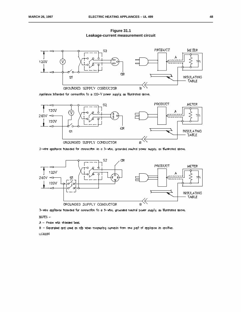
MARCH 26, 1997 ELECTRIC HEATING APPLIANCES – UL 499 48
Figure 31.1Leakage-current measurement circuit
49 ELECTRIC HEATING APPLIANCES – UL 499 JULY 17, 1998
31.7 A sample of the product is to be tested for leakage current starting with the as-received condition with allits switches and thermostats closed, but with its grounding conductor, if any, open at the attachment plug. Theas-received condition is defined as being without prior energization, except as may occur as part of theproduction-line testing. The supply voltage is to be 120, 208, or 240 V depending on product rating. The testsequence, with reference to the measuring circuit, Figure 31.1, is to be as follows:
a) With switch S1 open, the product is to be connected to the measuring circuit. Leakage current isto be measured using both positions of switch S2.
b) Switch S1 is then to be closed, energizing the appliance, and within a period of 5 seconds, theleakage current is to be measured using both positions of switch S2, and with the product operated atthe maximum heat setting of controls.
c) Leakage current is to be monitored from the time the appliance is energized until the productreaches thermal stabilization. Both positions of switch S2 are to be used. The equivalent of thermalstabilization is considered to be obtained as in the normal temperature test. If any thermostat does notcycle at the maximum heat setting, it is to be adjusted until it does cycle before the final measurementsare taken. Measurements are to be made with the thermostat, if any, open and closed. Uponevidence of stabilizing readings, intervals between measurements may be increased.
d) Monitoring of leakage current is to continue until the leakage current stabilizes or decreases afterthe product is turned off.
31.8 A sample will be carried through the complete leakage-current test program as covered by 31.7, withoutinterruption for other tests. However, with the concurrence of those concerned, the leakage-current tests maybe interrupted for the purpose of conducting other nondestructive tests.
31.9 When intended for permanent connection to the power supply, a liquid-heating appliance of the electrodetype and a product in which live parts of the heating element are in contact with the liquid shall not have aleakage current to ground in excess of 0.5 A with current flowing through the element or with one side of theline open as explained in 31.10.
*31.9 revised July 17, 1998*
31.10 To determine whether a liquid-heating appliance complies with the requirement in 31.9, the product isto be connected to a grounded supply circuit having full rated voltage between the ungrounded side of the lineand ground. The case is to be so mounted that it will be insulated from ground, and the liquid is to be suppliedby means of a rubber tube. A solution of 0.5 gram of calcium sulphate (CaSO @2H O) per liter of distilled water4 2is to be employed for the testing of a water heater constructed for general use. An ammeter is to be placedbetween the pipe connections on the heater and the water pipe or other ground, and leakage readings are tobe observed under all conditions representing an open fuse or fuses, except that in the case of a heaterconstructed and marked for use with a solid (unfused) and grounded neutral, the grounded conductor neednot be disconnected.
31.11 The greatest leakage current is usually noted with the maximum water temperature that, in the case ofan instantaneous or faucet heater, may be obtained by reducing the flow of water to a minimum.
31.12 The leakage current of a cord-connected liquid-heating appliance of the electrode type, or a product inwhich live parts of the heating element are in contact with the liquid, shall be investigated with reference to theinherent leakage current occurring during conditions of normal and abnormal use.
MARCH 26, 1997 ELECTRIC HEATING APPLIANCES – UL 499 50
32 Normal Temperature Test
32.1 General
32.1.1 A heating appliance, when tested under the conditions described in 32.1.3 – 32.2.12.1 shall comply withall four of the following conditions:
a) The product shall not attain at any point a temperature that would constitute a risk of fire or damageto any materials employed in the product.
b) At any time during the test, other than as indicated in 32.1.2, temperature rises at specific pointsshall not be greater than indicated in Table 32.1.
c) The product shall comply with the requirement in 6.1.
d) The product shall comply with the requirements in 28.3 (see Table 32.2).
32.1.2 Initial temperature transients may be in excess of the value shown in Table 32.1 if the duration andextent of the excursion do not result in a risk of fire or electric shock and do not unduly shorten the life of theproduct.
32.1.3 All values in Table 32.1 are based on an assumed room ambient temperature of 25EC (77EF), but atest may be conducted at any ambient temperature within the range of 10 – 40EC (50 – 104EF). However, ifthe operation of an automatic thermal control during the test limits the temperatures under observation, notemperature higher than 25EC plus the specified maximum rise is acceptable.
32.1.4 A gasket that is depended upon to keep water from entering into a heating appliance during cleaningshall not become hard or brittle, shall not crack, and shall show no other signs of deterioration as a result ofan accelerated-aging test in which the gasket is subjected to elevated temperatures. See 33.14.
32.1.5 The temperature to which the gasket is subjected during the test, as well as the duration of the test, isto be determined in accordance with the material of the gasket, the temperature to which it is subjected duringoperation, and other conditions of the particular application. Usually the product is to be operated dry and fora period of 240 hours.

51 ELECTRIC HEATING APPLIANCES – UL 499 MARCH 26, 1997
Table 32.1Maximum acceptable temperature rises
Materials and component parts EC (EF)
1. Any point within a terminal box or wiring compartment of a permanently connected heating 35 (63)appliance in which field-installed conductors are to be connected (including such conductorsthemselves) unless the product is marked in accordance with 45.7.
2. Any point on a surface adjacent to a heating appliance that is: 65 (117)
a) Permanently connected electrically or
b) Cord-connected and intended to be fastened in place or located in a dedicated space –including the surface on which the product is mounted, and specified points on test surfacesand enclosures at designated clearances from the product.
3. Fuses 65 (117)
4. Fiber used as electrical insulation or as cord bushings 65 (117)
5. Wood or other combustible material which is part of a heating appliance 65 (117)
6. Cotton or rayon braid of flexible cord 65 (117)
7. Class 105 insulation systems on winding of relays or solenoids, and the like:
Thermocouple method 65 (117)
Resistance method 85 (153)
8. Class A insulation systems on coil windings of a-c motors having a frame diameter of more than 7inches (178 mm) and of d-c and universal motors :
a,b
a) In open motors:
Thermocouple method 65 (117)
Resistance method 75 (135)
b) In totally enclosed motors
Thermocouple method 70 (126)
Resistance method 80 (144)
9. Class A insulation systems on coil windings of a-c motors (not including universal motors) having aframe diameter of 7 inches (178 mm) or less and on vibrator coils – thermocouple or resistancemethod :
a,b
a) In open motors and on vibrator coils 75 (135)
b) In totally enclosed motors 80 (144)
10. Class 130 insulation systems on winding of relays, solenoids, and the like:
Thermocouple method 85 (153)a
Resistance method 105 (189)
(Continued)
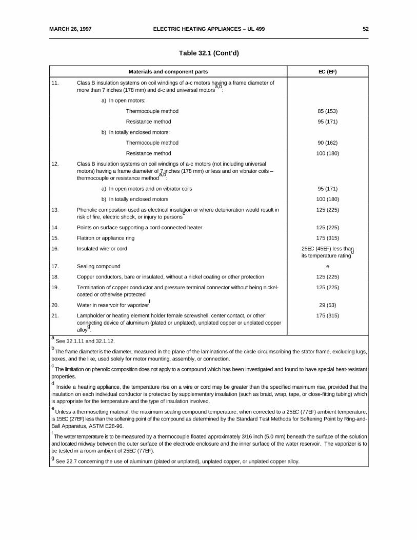
MARCH 26, 1997 ELECTRIC HEATING APPLIANCES – UL 499 52
Table 32.1 (Cont'd)
Materials and component parts EC (EF)
11. Class B insulation systems on coil windings of a-c motors having a frame diameter ofmore than 7 inches (178 mm) and d-c and universal motors :
a,b
a) In open motors:
Thermocouple method 85 (153)
Resistance method 95 (171)
b) In totally enclosed motors:
Thermocouple method 90 (162)
Resistance method 100 (180)
12. Class B insulation systems on coil windings of a-c motors (not including universalmotors) having a frame diameter of 7 inches (178 mm) or less and on vibrator coils –thermocouple or resistance method :
a,b
a) In open motors and on vibrator coils 95 (171)
b) In totally enclosed motors 100 (180)
13. Phenolic composition used as electrical insulation or where deterioration would result in 125 (225)risk of fire, electric shock, or injury to persons
c
14. Points on surface supporting a cord-connected heater 125 (225)
15. Flatiron or appliance ring 175 (315)
16. Insulated wire or cord 25EC (45EF) less thanits temperature rating
d
17. Sealing compound e
18. Copper conductors, bare or insulated, without a nickel coating or other protection 125 (225)
19. Termination of copper conductor and pressure terminal connector without being nickel- 125 (225)coated or otherwise protected
20. Water in reservoir for vaporizer 29 (53)f
21. Lampholder or heating element holder female screwshell, center contact, or other 175 (315)connecting device of aluminum (plated or unplated), unplated copper or unplated copperalloy .
g
See 32.1.11 and 32.1.12.a
The frame diameter is the diameter, measured in the plane of the laminations of the circle circumscribing the stator frame, excluding lugs,b
boxes, and the like, used solely for motor mounting, assembly, or connection.
The limitation on phenolic composition does not apply to a compound which has been investigated and found to have special heat-resistantc
properties.
Inside a heating appliance, the temperature rise on a wire or cord may be greater than the specified maximum rise, provided that thed
insulation on each individual conductor is protected by supplementary insulation (such as braid, wrap, tape, or close-fitting tubing) whichis appropriate for the temperature and the type of insulation involved.
Unless a thermosetting material, the maximum sealing compound temperature, when corrected to a 25EC (77EF) ambient temperature,e
is 15EC (27EF) less than the softening point of the compound as determined by the Standard Test Methods for Softening Point by Ring-and-Ball Apparatus, ASTM E28-96.
The water temperature is to be measured by a thermocouple floated approximately 3/16 inch (5.0 mm) beneath the surface of the solutionf
and located midway between the outer surface of the electrode enclosure and the inner surface of the water reservoir. The vaporizer is tobe tested in a room ambient of 25EC (77EF).
See 22.7 concerning the use of aluminum (plated or unplated), unplated copper, or unplated copper alloy.g
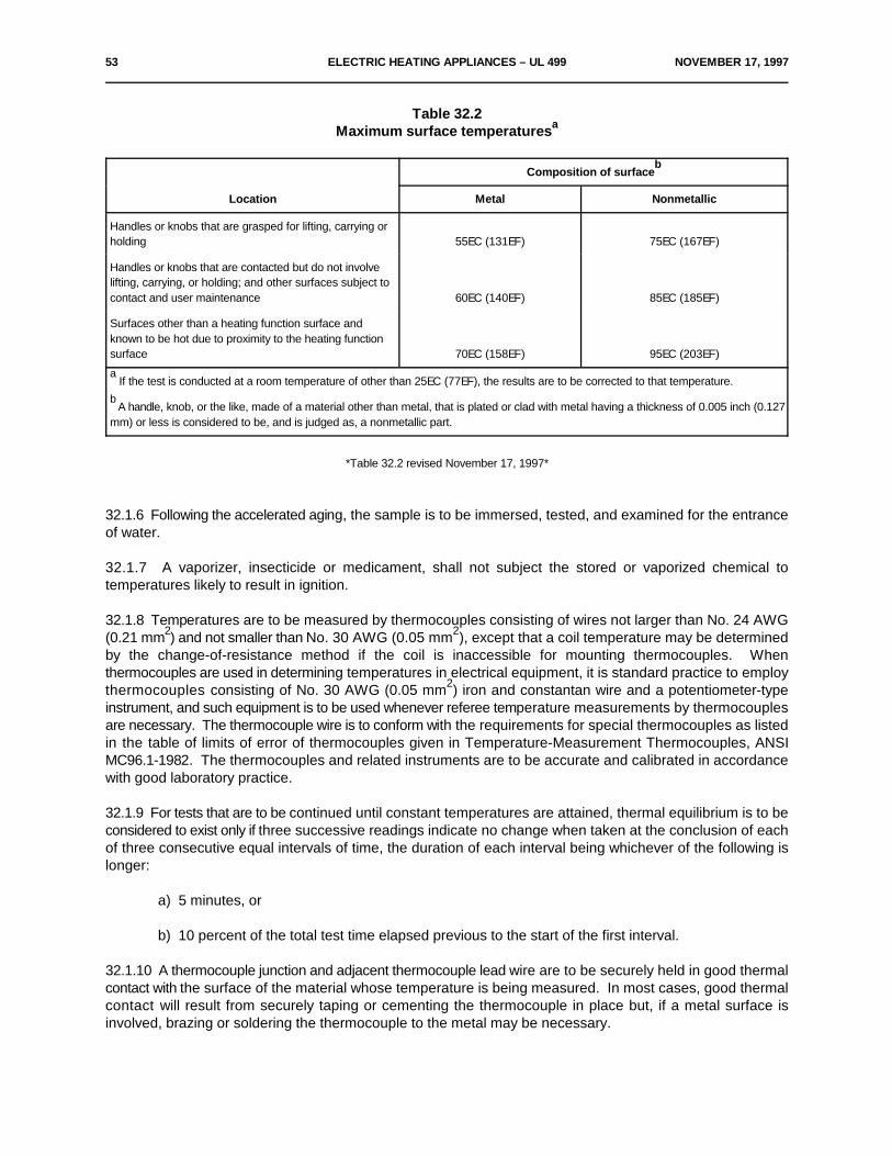
53 ELECTRIC HEATING APPLIANCES – UL 499 NOVEMBER 17, 1997
Table 32.2Maximum surface temperaturesa
Location Metal Nonmetallic
Composition of surfaceb
Handles or knobs that are grasped for lifting, carrying orholding 55EC (131EF) 75EC (167EF)
Handles or knobs that are contacted but do not involvelifting, carrying, or holding; and other surfaces subject tocontact and user maintenance 60EC (140EF) 85EC (185EF)
Surfaces other than a heating function surface andknown to be hot due to proximity to the heating functionsurface 70EC (158EF) 95EC (203EF)
If the test is conducted at a room temperature of other than 25EC (77EF), the results are to be corrected to that temperature.a
A handle, knob, or the like, made of a material other than metal, that is plated or clad with metal having a thickness of 0.005 inch (0.127b
mm) or less is considered to be, and is judged as, a nonmetallic part.
*Table 32.2 revised November 17, 1997*
32.1.6 Following the accelerated aging, the sample is to be immersed, tested, and examined for the entranceof water.
32.1.7 A vaporizer, insecticide or medicament, shall not subject the stored or vaporized chemical totemperatures likely to result in ignition.
32.1.8 Temperatures are to be measured by thermocouples consisting of wires not larger than No. 24 AWG(0.21 mm ) and not smaller than No. 30 AWG (0.05 mm ), except that a coil temperature may be determined2 2
by the change-of-resistance method if the coil is inaccessible for mounting thermocouples. Whenthermocouples are used in determining temperatures in electrical equipment, it is standard practice to employthermocouples consisting of No. 30 AWG (0.05 mm ) iron and constantan wire and a potentiometer-type2
instrument, and such equipment is to be used whenever referee temperature measurements by thermocouplesare necessary. The thermocouple wire is to conform with the requirements for special thermocouples as listedin the table of limits of error of thermocouples given in Temperature-Measurement Thermocouples, ANSIMC96.1-1982. The thermocouples and related instruments are to be accurate and calibrated in accordancewith good laboratory practice.
32.1.9 For tests that are to be continued until constant temperatures are attained, thermal equilibrium is to beconsidered to exist only if three successive readings indicate no change when taken at the conclusion of eachof three consecutive equal intervals of time, the duration of each interval being whichever of the following islonger:
a) 5 minutes, or
b) 10 percent of the total test time elapsed previous to the start of the first interval.
32.1.10 A thermocouple junction and adjacent thermocouple lead wire are to be securely held in good thermalcontact with the surface of the material whose temperature is being measured. In most cases, good thermalcontact will result from securely taping or cementing the thermocouple in place but, if a metal surface isinvolved, brazing or soldering the thermocouple to the metal may be necessary.
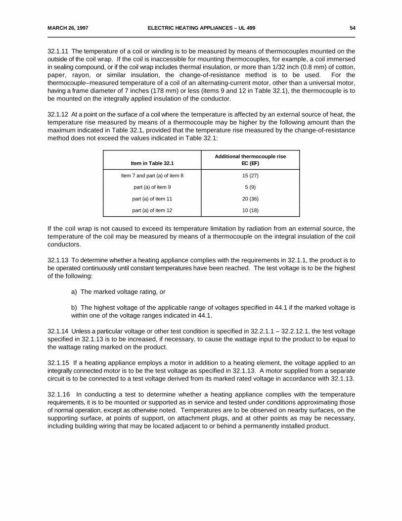
MARCH 26, 1997 ELECTRIC HEATING APPLIANCES – UL 499 54
32.1.11 The temperature of a coil or winding is to be measured by means of thermocouples mounted on theoutside of the coil wrap. If the coil is inaccessible for mounting thermocouples, for example, a coil immersedin sealing compound, or if the coil wrap includes thermal insulation, or more than 1/32 inch (0.8 mm) of cotton,paper, rayon, or similar insulation, the change-of-resistance method is to be used. For thethermocouple–measured temperature of a coil of an alternating-current motor, other than a universal motor,having a frame diameter of 7 inches (178 mm) or less (items 9 and 12 in Table 32.1), the thermocouple is tobe mounted on the integrally applied insulation of the conductor.
32.1.12 At a point on the surface of a coil where the temperature is affected by an external source of heat, thetemperature rise measured by means of a thermocouple may be higher by the following amount than themaximum indicated in Table 32.1, provided that the temperature rise measured by the change-of-resistancemethod does not exceed the values indicated in Table 32.1:
Item in Table 32.1 EC (EF)Additional thermocouple rise
Item 7 and part (a) of item 8 15 (27)
part (a) of item 9 5 (9)
part (a) of item 11 20 (36)
part (a) of item 12 10 (18)
If the coil wrap is not caused to exceed its temperature limitation by radiation from an external source, thetemperature of the coil may be measured by means of a thermocouple on the integral insulation of the coilconductors.
32.1.13 To determine whether a heating appliance complies with the requirements in 32.1.1, the product is tobe operated continuously until constant temperatures have been reached. The test voltage is to be the highestof the following:
a) The marked voltage rating, or
b) The highest voltage of the applicable range of voltages specified in 44.1 if the marked voltage iswithin one of the voltage ranges indicated in 44.1.
32.1.14 Unless a particular voltage or other test condition is specified in 32.2.1.1 – 32.2.12.1, the test voltagespecified in 32.1.13 is to be increased, if necessary, to cause the wattage input to the product to be equal tothe wattage rating marked on the product.
32.1.15 If a heating appliance employs a motor in addition to a heating element, the voltage applied to anintegrally connected motor is to be the test voltage as specified in 32.1.13. A motor supplied from a separatecircuit is to be connected to a test voltage derived from its marked rated voltage in accordance with 32.1.13.
32.1.16 In conducting a test to determine whether a heating appliance complies with the temperaturerequirements, it is to be mounted or supported as in service and tested under conditions approximating thoseof normal operation, except as otherwise noted. Temperatures are to be observed on nearby surfaces, on thesupporting surface, at points of support, on attachment plugs, and at other points as may be necessary,including building wiring that may be located adjacent to or behind a permanently installed product.
55 ELECTRIC HEATING APPLIANCES – UL 499 MARCH 26, 1997
32.1.17 A heating appliance intended to be permanently connected to the power supply or a product that iscord-connected and that is intended to be fastened in place or located in a dedicated space is to be supportedin the intended manner on black-painted wood not less than 3/8 inch (9.5 mm) thick and is to be located in acorner – vertical walls meeting at a right angle – formed by two black-painted, vertical sheets of 3/8-inch (9.5-mm) plywood having such width and height that they extend not less than 2 ft (610 mm) beyond the physicallimits of the heater. The heater is to be located as close to both walls of the corner as its construction permits,and it is to be so placed relative to the walls that maximum heating of the walls will occur, except that it may bespaced away from the walls to limit the wall temperatures from rising more than 65EC (117EF) if the heater ismarked as described in 45.9.
32.1.18 Unless otherwise indicated in the description of the test for a specific product, a cord-connectedproduct is to be supported on two layers of white tissue paper on a softwood surface.
32.1.19 An automatic temperature-regulating or -limiting control or other protective device is to be shunted outof the circuit, unless the control has been shown, in accordance with Table 38.1, to be rugged, reliable, andunlikely to be defeated by the user. The control is considered to be unlikely to be defeated if tools are requiredto gain access to the control, or a positive stop is incorporated in the control.
32.1.20 If the construction of a heating appliance is such that cooking or heating of a liquid is a determiningfactor in the temperature attained, the intended duty of a product is to be taken into consideration. Normaloperating conditions cannot be obtained, however, if certain types of products are operated continuously andin a dry condition. Accordingly, in determining whether a product complies with the requirements in 32.1.1,actual service conditions or an approximation thereof are to be employed. Unless otherwise specificallyindicated below:
a) If the appliance is controlled by an adjustable thermostat, the thermostat is to be set to givemaximum temperatures, and
b) If the product is controlled by a nonadjustable thermostat, it is to operate at whatever temperaturethe thermostat permits.
In each case, operation is to be continued until temperatures are stabilized.
32.1.21 A product that may be either open or closed in actual service, such as a heat transfer press, is to betested both open and closed to determine which condition produces the higher operating temperature. In thecase of an open-front tabletop product, where some heating operation may be performed without a tray inplace, temperatures are to be measured on the horizontal supporting surface in front of the open face of theproduct.
32.1.22 External thermal insulation, such as woven glass fiber or mineral wool, is to be removed before aheating appliance is installed in the test enclosure unless the material is bonded or permanently attached tothe product. Rubber or other material similarly subject to deterioration is to be removed from feet or othersupports if the removal of the material is likely to result in higher temperatures being attained on the product.
32.1.23 Wherever cheesecloth is mentioned in connection with either a temperature test or an abnormal test,the cloth is to be bleached cheesecloth running 14 – 15 yd/lb (approximately 28 – 30 m/kg) and having whatis known to the trade as a "count of 32 x 28" – that is, for any square inch, 32 threads in one direction and 28threads in the other direction (for any square centimeter, 13 threads in one direction and 11 threads in the otherdirection).
MARCH 26, 1997 ELECTRIC HEATING APPLIANCES – UL 499 56
32.2 Specific test conditions
32.2.1 General
32.2.1.1 For most of the common types of heating appliances, standardized normal conditions for thetemperature tests are given in 32.2.2.1 – 32.2.11.1.
32.2.2 Ceramics-baking kilns and ovens
32.2.2.1 If marked with a warning statement as indicated in 45.17, the product is to be operated until theinternal temperature reaches a value indicated in that statement, and the power supply is then to be cut off.Temperatures are to be recorded over such interval as may be necessary to determine that the maximumshave been observed. In the absence of the marking mentioned above, the product is to be operated untilobserved temperatures have become stabilized, and they are then to be recorded.
32.2.3 Charcoal ignitors
32.2.3.1 A cord-connected charcoal ignitor is to be operated until maximum temperatures are reached in abrazier-held conical bed of charcoal briquettes that is 18 inches (457 mm) in diameter and 4 inches (102 mm)high. The diameter of the brazier is to be 24 inches (610 mm) and the bed of charcoal is to be located tangentto the brazier rim. The center of the area enclosed by the heated ignitor element is to be located as close tothe center of the bed of charcoal as the length of the heating element permits but, in any case, the handle ofthe ignitor is to be outside the rim of the brazier at the point at which the charcoal bed is tangent to the rim. Atthe conclusion of the normal temperature test, operation is to be continued as described in 38.2.4.2.
32.2.4 Stock-tank de-icers, stock waterers, and the like
32.2.4.1 A device intended for heating in low-temperature air is to be operated in the intended manner whilein air at 25EC (77EF) and while in air at minus 23.0 ±3.0EC (minus 9.4 ±5.4EF). The temperature limitations areto be those indicated in Table 32.1 plus 25EC.
32.2.5 Liquid heaters and vaporizers, cord-connected
32.2.5.1 The product is to be operated continuously with water. If the product is of the immersed-electrodetype, a hard water solution of:
a) 0.5 gram of calcium sulphate (CaSO @2H O) per liter of distilled water and4 2
b) 0.25 gram of calcium sulphate per liter of distilled water plus the manufacturers' amount and typeof recommended additive
are to be used in separate tests starting with the water reservoir or container filled to its filled level mark.Operation is to be continued after temperatures have stabilized and until 75 percent of the water reservoirsupply has been dissipated, while monitoring the reservoir water temperature, see item 20 of Table 32.1.
32.2.6 Poultry and livestock brooders
32.2.6.1 If marked in accordance with 45.20, a brooder is to be tested while mounted at the height above thesupporting surface recommended by the manufacturer. A brooder not so marked is to be tested while mountedas close to the supporting surface as its construction will permit. If the product has an adjustable temperaturecontrol, it is to be set at the value recommended by the manufacturer.
57 ELECTRIC HEATING APPLIANCES – UL 499 MARCH 26, 1997
32.2.7 Soldering irons and soldering guns and desoldering tools
32.2.7.1 A product equipped with a momentary-contact switch, such as a high-speed resistance-type solderingiron or a transformer-type soldering gun, is to be tested as follows. The product is to be connected to a circuitthat provides the test voltage indicated in 32.1.13 and is to be supported at an angle of 45 degrees from thehorizontal with its tips resting in a pool of solder approximately 1/2 inch (13 mm) in diameter. It is to be operatedin cycles of 1 minute on and 4 minutes off until stabilized temperatures are attained. An iron or desoldering toolof any other type is to be operated continuously until temperatures become stabilized, while resting on its standwith the applied voltage reduced to give a temperature of 275EC (527EF) at the tip.
32.2.8 Solder pots, nonautomatic
32.2.8.1 For a nonautomatic solder pot in which means are provided to adjust the heat to values for meltingdifferent metals or alloys, and that is plainly and permanently marked to indicate which wattage setting shouldbe used for each metal or alloy, the test is to be performed as follows: the solder pot is to be operated at eachsetting until temperatures become stabilized, while charged with the metal or alloy corresponding to that setting,as indicated in the marking.
32.2.9 Warming trays
32.2.9.1 Warming trays, intended to receive only vessels on the heated surface, are to be operatedcontinuously with the thermostat set at the maximum-heat position and with the surface empty. If the thermostatcycles, the test is to be repeated with a vessel – containing water to a minimum depth of 1 inch (25 mm) –placed on the heating surface over the thermostat. The vessel will usually consist of a 6-inch (152-mm)diameter shallow pan.
32.2.10 Water heaters of the side-arm type
32.2.10.1 A water temperature of 77.0EC (170.6EF) is considered to be the highest normal value.
32.2.11 Refrigerator defrosters
32.2.11.1 No external surface of a refrigerator defroster shall exceed 100EC (180EF) rise over ambienttemperature. See 45.29.
32.2.12 Heat guns
32.2.12.1 The temperature rise of the supporting surface of a heat gun incorporating a built-in stand shall notexceed 125EC (225EF) when tested in accordance with 32.1.1 with the heat gun utilizing its stand with allpossible combinations of attachments available for the heat gun.
33 Test of Insulation Resistance and Leakage Current as a Result of Moisture
33.1 A product employing insulation material likely to be adversely affected by moisture under condition ofintended use shall be conditioned for 48 hours in moist air having a relative humidity of 88 ±2 percent at atemperature of 32.0 ±2.0EC (89.6 ±3.6EF). After the conditioning:
a) A cord-connected product rated for a nominal 120-, 208-, or 240-V supply shall comply with therequirement in 31.1 in a repeat leakage-current test, except that the test shall be discontinued whenleakage current stabilizes.
b) A product other than mentioned in (a) shall have an insulation resistance of not less than 50,000ohms between live parts and interconnected dead metal parts.
MARCH 26, 1997 ELECTRIC HEATING APPLIANCES – UL 499 58
33.2 The insulation resistance is to be measured by:
a) A magneto megohmmeter that has an open circuit output of 500 V,
b) A voltmeter having an internal resistance of at least 30,000 ohms and using a 250-V d-c circuit, or
c) Equivalent equipment.
33.3 A product that by design and intended use can be expected to be used outdoors – for example, a stock-tank de-icer, or charcoal ignitor, or heat gun – and a product such as a refrigerator defroster, which may beexposed to wet or moist conditions, when tested after being conditioned as indicated in 33.4 – 33.6:
a) If a cord-connected product rated for a nominal 120-, 208-, or 240-V supply, shall comply with therequirement in 31.1 in a repeat leakage-current test, except that the test shall be discontinued whenleakage current stabilizes.
b) If a product other than those mentioned in (a), shall have an insulation resistance of not less than50,000 ohms.
c) Shall also be capable of withstanding without breakdown for a period of 1 minute, the applicationof a 60 Hz essentially sinusoidal potential between live parts and interconnected dead-metal parts.The dielectric voltage-withstand test potential shall be 1000 V if the product is rated 250 V or less, andshall be 1000 V plus twice rated voltage if the product is rated more than 250 V.
33.4 After being conditioned as follows, and in the sequence indicated, each of two samples of a charcoalignitor is to be tested first for leakage current and then dielectric voltage-withstand as indicated in 33.3.
a) Each sample is to be placed on a horizontal thermally insulated surface and operated at the voltageindicated in 32.1.13 – 32.1.15 for 2-1/2 hours, given time to cool to room temperature, operated for anadditional 2-1/2 hours, again given time to cool to room temperature, and so forth, for a total on timeof 500 hours.
b) One unenergized sample is then to be placed in a horizontal position on a platform and subjectedfor 4 hours to a water spray applied at an angle of 45E from the vertical and adjusted to be equivalentto a beating rain. The second sample, unenergized, is also to be subjected to the spray but, beforethe spray is started, this sample is to be placed in the position most likely to result in wetting of theelectrical insulation.
33.5 After being conditioned as follows, and in the sequence indicated, each of two samples of a refrigeratordefroster is to be tested first for leakage current and then dielectric voltage-withstand as indicated in 33.3:
a) Each sample is to be placed on a horizontal thermally insulated surface and operated continuouslyfor 500 hours at the voltage indicated in 32.1.13 – 32.1.15.
b) One sample is then to be energized at rated voltage, placed in a horizontal position on a platform,and then subjected for 4 hours to a water spray applied at an angle of 45 degrees from the vertical andadjusted to be equivalent to a beating rain. The second sample is also to be energized at rated voltageand subjected to the spray but, before the spray is started, this sample is to be placed in the positionmost likely to result in wetting of the electrical insulation.
59 ELECTRIC HEATING APPLIANCES – UL 499 MARCH 26, 1997
33.6 Except for a charcoal lighter, one sample of a product that can be expected to be used outdoors is to bemounted as in actual service – the product is to be mounted in any shield or other shelter that the manufacturerprovides for use with the product. While so mounted and without being energized the product is to be subjectedfor 4 hours to a water spray applied at an angle 45E from the vertical and adjusted to be equivalent to a beatingrain. After this conditioning and while still mounted, the product is to be tested first for leakage current or forinsulation resistance and then dielectric voltage-withstand as indicated in 33.3.
Exception No. 1: A heat gun need not be subjected to the water-spray test described in 33.6 if the dew pointtest described in 33.7 – 33.9 is performed.
Exception No. 2: A heat gun need not be subjected to the water-spray test described in 33.6 if the markingdescribed in the exception to 45.30 is provided, but shall be subjected to the dew point test described in 33.7– 33.9.
33.7 A heat gun, as mentioned in the exceptions to 33.6, shall not have a leakage current greater than 2.0 mAafter being conditioned as described in 33.8 and 33.9. Following conditioning, a heat gun with a leakage currentthat exceeds 0.5 mA shall be additionally tested as follows: after a minimum of 10 hours storage at roomtemperature and humidity, or after 1 hour running on the lowest heat setting, the leakage current shall notexceed 0.5 mA.
33.8 The heat gun is to be conditioned in a cold chamber at 5.0 ±2.0EC (41.0 ±3.6EF) for at least 4 hours, thentransferred from the cold chamber to a humidity chamber at 88 ±2 percent relative humidity at 32.0 ±2.0EC(89.6 ±3.6EF). The transfer time shall not exceed 1 minute.
33.9 Immediately after being placed in the humidity chamber, the leakage current is to be measured betweenall exposed conductive surfaces and all gripping surfaces and earth ground with the heat gun connected to theintended branch-circuit supply but not operating. The leakage current shall be continuously monitored until itstabilizes or drops.
33.10 In the case of a warming tray, a volume of hard water solution made as described in 31.10 and insufficient quantity to cover the product surface to a depth of 5 mm, is to be sponged over the serving surface.The sponging operation is to consist of using the volume of water described above in a simulated cleaningoperation with the water being allowed to drain from the edges. At the conclusion of this test, the leakage-current or insulation-resistance and the dielectric voltage-withstand tests described in 33.3 are to be conducted.The leakage current is not to exceed 0.5 mA.
33.11 Except as noted in 33.12, a product that can be expected to be immersed in water for cleaning shallshow a leakage current of not more than 0.5 mA and shall be capable of withstanding a potential of 1000 Vwhen tested in accordance with 33.12 – 33.15. The test shall not result in the entrance of water into the interiorof the product such that the water might come into contact with uninsulated live parts.
33.12 A product marked to indicate that it is not intended for immersion need not comply with the requirementsin 33.11. See 45.19.
33.13 Three samples of the product are to be heated and are then to be immersed immediately in water ata temperature of 10 – 25EC (50 – 77EF). The immersion is to be complete unless the product is marked toindicate that it is intended for partial immersion only, see 45.19, in which case each product is to be immersedonly to the extent indicated. After 1 hour of immersion, the samples are to be removed from the water, driedwith a soft cloth to remove all surface moisture, including surface moisture from terminal pins, and the samplesare to be tested for leakage current as indicated in 33.3.
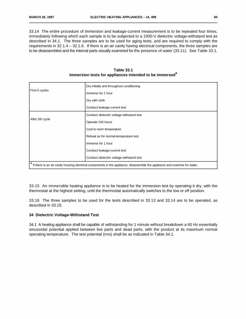
MARCH 26, 1997 ELECTRIC HEATING APPLIANCES – UL 499 60
33.14 The entire procedure of immersion and leakage-current measurement is to be repeated four times,immediately following which each sample is to be subjected to a 1000-V dielectric voltage-withstand test asdescribed in 34.1. The three samples are to be used for aging tests, and are required to comply with therequirements in 32.1.4 – 32.1.6. If there is an air cavity having electrical components, the three samples areto be disassembled and the internal parts visually examined for the presence of water (33.11). See Table 33.1.
Table 33.1Immersion tests for appliances intended to be immerseda
First 5 cyclesDry initially and throughout conditioning
Immerse for 1 hour
Dry with cloth
Conduct leakage-current test
After 5th cycleConduct dielectric voltage-withstand test
Operate 240 hours
Cool to room temperature
Reheat as for normal-temperature test
Immerse for 1 hour
Conduct leakage-current test
Conduct dielectric voltage-withstand test
If there is an air cavity housing electrical components in the appliance, disassemble the appliance and examine for water.a
33.15 An immersible heating appliance is to be heated for the immersion test by operating it dry, with thethermostat at the highest setting, until the thermostat automatically switches to the low or off position.
33.16 The three samples to be used for the tests described in 33.13 and 33.14 are to be operated, asdescribed in 33.15.
34 Dielectric Voltage-Withstand Test
34.1 A heating appliance shall be capable of withstanding for 1 minute without breakdown a 60 Hz essentiallysinusoidal potential applied between live parts and dead parts, with the product at its maximum normaloperating temperature. The test potential (rms) shall be as indicated in Table 34.1.
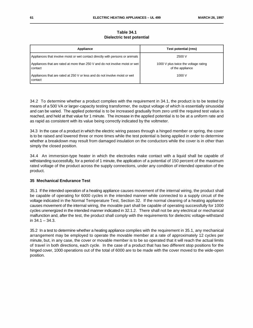
61 ELECTRIC HEATING APPLIANCES – UL 499 MARCH 26, 1997
Table 34.1Dielectric test potential
Appliance Test potential (rms)
Appliances that involve moist or wet contact directly with persons or animals 2500 V
Appliances that are rated at more than 250 V and do not involve moist or wet 1000 V plus twice the voltage ratingcontact of the appliance
Appliances that are rated at 250 V or less and do not involve moist or wet 1000 Vcontact
34.2 To determine whether a product complies with the requirement in 34.1, the product is to be tested bymeans of a 500 VA or larger-capacity testing transformer, the output voltage of which is essentially sinusoidaland can be varied. The applied potential is to be increased gradually from zero until the required test value isreached, and held at that value for 1 minute. The increase in the applied potential is to be at a uniform rate andas rapid as consistent with its value being correctly indicated by the voltmeter.
34.3 In the case of a product in which the electric wiring passes through a hinged member or spring, the coveris to be raised and lowered three or more times while the test potential is being applied in order to determinewhether a breakdown may result from damaged insulation on the conductors while the cover is in other thansimply the closed position.
34.4 An immersion-type heater in which the electrodes make contact with a liquid shall be capable ofwithstanding successfully, for a period of 1 minute, the application of a potential of 150 percent of the maximumrated voltage of the product across the supply connections, under any condition of intended operation of theproduct.
35 Mechanical Endurance Test
35.1 If the intended operation of a heating appliance causes movement of the internal wiring, the product shallbe capable of operating for 6000 cycles in the intended manner while connected to a supply circuit of thevoltage indicated in the Normal Temperature Test, Section 32. If the normal cleaning of a heating appliancecauses movement of the internal wiring, the movable part shall be capable of operating successfully for 1000cycles unenergized in the intended manner indicated in 32.1.2. There shall not be any electrical or mechanicalmalfunction and, after the test, the product shall comply with the requirements for dielectric voltage-withstandin 34.1 – 34.3.
35.2 In a test to determine whether a heating appliance complies with the requirement in 35.1, any mechanicalarrangement may be employed to operate the movable member at a rate of approximately 12 cycles perminute, but, in any case, the cover or movable member is to be so operated that it will reach the actual limitsof travel in both directions, each cycle. In the case of a product that has two different stop positions for thehinged cover, 1000 operations out of the total of 6000 are to be made with the cover moved to the wide-openposition.
MARCH 26, 1997 ELECTRIC HEATING APPLIANCES – UL 499 62
35.3 If flexing or internal electric wiring or uninsulated live parts occurs during installation or inspection ofelectrical field-wiring connections, see 10.1.1.5, then internal electric wiring or uninsulated live parts are to beflexed 50 cycles under the conditions specified in 35.4.
35.4 Prior to the flexing test required in 35.3, the terminal box or area adjacent to the component terminationleads shall be filled with the field-wiring leads, branch-circuit wiring, and the like, as would be encountered inintended use. Flexing of the component leads shall not result in damage to the electrical insulation in theflexing area or disarrangement of the electrical connections that would preclude proper storage of thecomponent connecting leads and there shall be no electrical or mechanical malfunction. After the test, theproduct shall comply with the requirements for dielectric voltage-withstand in 34.1 – 34.3.
36 Resistance to Impact
36.1 The material of a reservoir, the breakage of which may result in risk of fire or electric shock, shall havesuch properties as to meet the conditions anticipated in use.
36.2 The reservoir mentioned in the Exception to 11.3 shall withstand the applicable impact test described in36.3 or 36.6 without cracking, breaking or sustaining other damage that could cause leaking of the liquid it isintended to contain.
36.3 Each of three samples of a product that is hand-supported in normal use is to be subjected to the impactthat results from the product being dropped through a distance of 3 feet (914 mm) onto a hardwood surface.Depending upon intended usage, the product is to be dropped so as to strike the floor in the positions mostlikely to produce adverse results.
36.4 The hardwood surface mentioned in 36.3 is to consist of a layer of nominal 1-inch (25-mm) thick tongue-and-grove oak flooring mounted on two layers of 3/4-inch (19-mm) thick plywood. The hard-wood surfaceassembly is to rest on a concrete floor or the equivalent during the test.
36.5 With reference to 36.3, the test on the product is to be conducted so that each sample strikes the surfacein a position different from those of the other two samples. Three individual samples may be employed for thetests, or if the manufacturer so elects, fewer samples may be used in accordance with Figure 36.1. The overallperformance is acceptable upon acceptable completion of any one of the procedures represented in the table.If any sample is not acceptable on its first drop in any of three positions, the results of the test are unacceptable.
36.6 A product not normally hand-supported is to be subjected to an impact as required in Table 36.1 on anysurface that is susceptible to a blow during normal use. For the top surface the impact is to be produced bydropping a steel sphere, 2 inches (50.8 mm) in diameter and weighing approximately 1.18 lb (535 g), from theheight necessary to produce the specified impact as shown in Figure 36.2. The steel sphere shall strike thesurface in a location different from those in the other two impacts. For surfaces other than the top of theproduct, the steel sphere is to be suspended by a cord and allowed to swing as a pendulum, dropping throughthe vertical distance necessary to cause it to strike the surface with the specified impact as shown in Figure36.2.
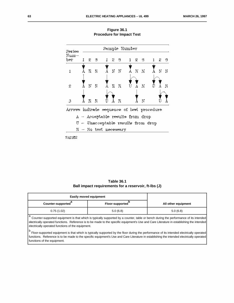
63 ELECTRIC HEATING APPLIANCES – UL 499 MARCH 26, 1997
Figure 36.1Procedure for Impact Test
Table 36.1Ball impact requirements for a reservoir, ft-lbs (J)
Easily moved equipment
All other equipmentCounter-supported Floor-supporteda b
0.75 (1.02) 5.0 (6.8) 5.0 (6.8)
Counter-supported equipment is that which is typically supported by a counter, table or bench during the performance of its intendeda
electrically operated functions. Reference is to be made to the specific equipment's Use and Care Literature in establishing the intendedelectrically operated functions of the equipment.
Floor-supported equipment is that which is typically supported by the floor during the performance of its intended electrically operatedb
functions. Reference is to be made to the specific equipment's Use and Care Literature in establishing the intended electrically operatedfunctions of the equipment.
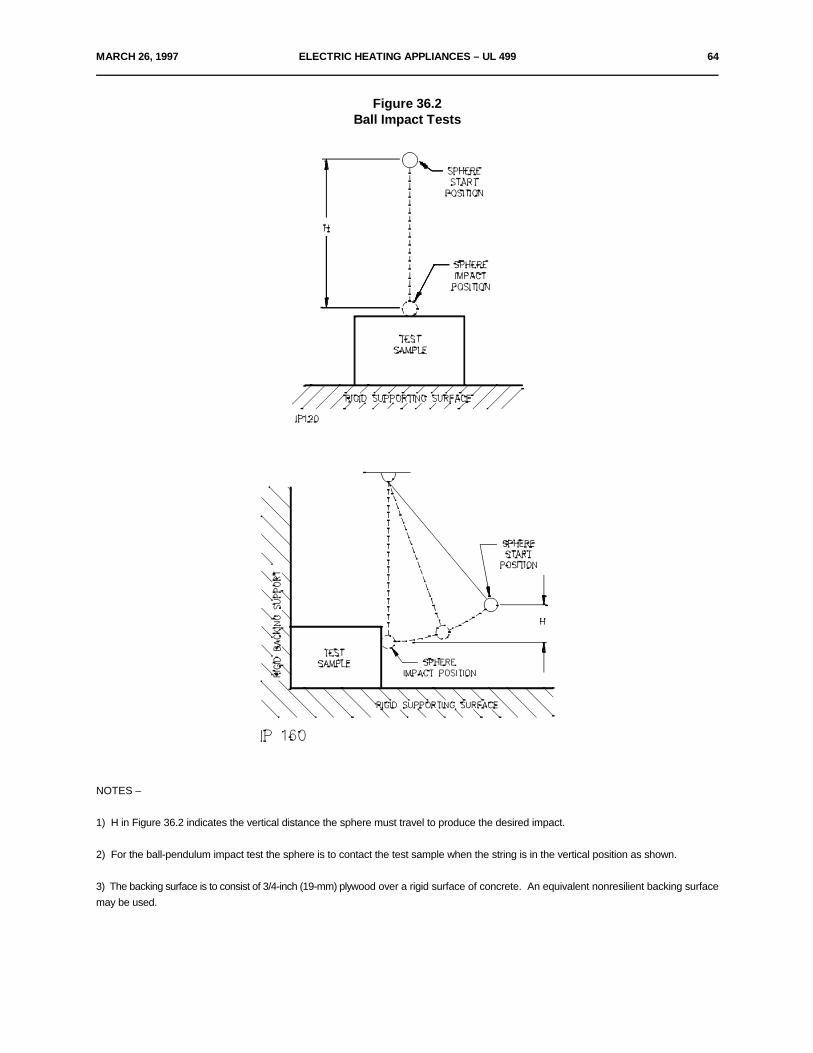
MARCH 26, 1997 ELECTRIC HEATING APPLIANCES – UL 499 64
Figure 36.2Ball Impact Tests
NOTES –
1) H in Figure 36.2 indicates the vertical distance the sphere must travel to produce the desired impact.
2) For the ball-pendulum impact test the sphere is to contact the test sample when the string is in the vertical position as shown.
3) The backing surface is to consist of 3/4-inch (19-mm) plywood over a rigid surface of concrete. An equivalent nonresilient backing surfacemay be used.
65 ELECTRIC HEATING APPLIANCES – UL 499 MARCH 26, 1997
36.7 A product is to be subjected to the applicable impact test described in 36.3 or 36.6 with or without anyattachment recommended by the manufacturer, whichever would result in the most severe test.
36.8 After the applicable Impact Test of 36.3 or 36.6 the product shall:
a) Comply with the Dielectric Voltage-Withstand Test, Section 34,
b) Comply with the Leakage Current Test requirement of 38.1.4 and,
c) Have no accessible uninsulated live parts or enamel-insulated wires as determined by theapplication of the probe shown in Figure 6.2.
37 Overflow Test
37.1 If a heating appliance – such as a vaporizer, sterilizer, or the like – incorporates a reservoir or liquid-storage chamber that is likely to be overfilled in intended use, liquid overflowing from the reservoir or chambershall not wet uninsulated live parts or enamel-insulated wires, and shall not wet electrical insulation that is likelyto be adversely affected by the liquid usually used in the reservoir or chamber.
37.2 To determine whether a product complies with the requirement in 37.1, it is to be tested as follows: wateris to be used for the test and is to be poured into the reservoir through an orifice 3/8 inch (9.5 mm) in diameter.The reservoir is to be filled to the level recommended by the manufacturer if such level is plainly marked;otherwise, the reservoir is to be filled to maximum capacity. Additional water, equal to 50 percent of the volumejust mentioned, but not more than 1 pint (470 mL), is then to be poured into the reservoir. Determination ofwhether uninsulated live parts have become wet as a result of the overflow is to be by means of visualinspection, but this may be supplemented by an insulation-resistance test, a dielectric voltage-withstand test,or both if considered to be appropriate.
38 Abnormal Operation Test
38.1 General
38.1.1 If the conditions of normal operation are not representative also of abnormal conditions likely to beobtained in actual service, a heating appliance shall not involve the risk of fire or electric shock when operatedcontinuously under such abnormal conditions.
38.1.2 To determine whether a risk of fire or electric shock actually exists, a separate burnout or abnormal testis to be conducted with the product operating continuously until the ultimate result has been observed. Unlessotherwise indicated, the test is to be conducted with the applied voltage, method of mounting and thermostatconnection in accordance with 32.1.13 – 32.1.16 and 32.1.19. In most cases, continuous operation for 7 to 8hours will be necessary to determine the ultimate result. A cord-connected product is to be placed on whitetissue paper on a soft wood surface.
38.1.3 When operated under such abnormal conditions, a product is considered to involve a risk of fire if thereis any emission of flame or molten metal, other than drops of melted solder, or if the operation of the productresults in the glowing or flaming of combustible material upon which the product may be placed or – in the caseof a permanently installed product – may be in proximity to the product as installed.

MARCH 26, 1997 ELECTRIC HEATING APPLIANCES – UL 499 66
38.1.4 After having been subjected to an abnormal test, the cord-connected heating appliance is consideredto involve a risk of electric shock if the current measured through a 500-ohm resistor between an accessiblepart and ground is more than 5 mA. The current need not be measured at terminals operating at voltage levelsthat do not involve a risk of electric shock. In the case of a product utilizing a liquid in its intended operation,the liquid container is to be filled with the hard-water solution described in 31.10 in the intended manner, priorto the current measurement. Liquid need not be added if it is obviously apparent that the product will not holdliquid. Otherwise, water in an amount equal to the capacity of the container is to be poured into the containerand the current is to be measured as quickly as possible thereafter.
38.1.5 If a motor is connected across a portion of a resistance element, the product shall not involve a risk offire or electric shock as the result of an open circuit in the portion of the element that is in parallel with themotor.
38.2 Specific test conditions
38.2.1 General
38.2.1.1 For most of the common types of heating appliances, standardized abnormal test conditions are givenin 38.2.2.1 – 38.2.17.1.
38.2.2 Products with breakable exterior surfaces
38.2.2.1 If a product, such as a warming tray, has an exterior surface of glass, ceramic, or comparably brittlematerial in or on which the heating element is mounted or that is an essential part of the enclosure of live parts,the material shall be capable of withstanding the stresses likely to be encountered in actual service.
38.2.2.2 Certain specific tests are described in 38.2.3.1 – 38.2.3.3, but other tests may be necessitated by thedesign or intended operation of the product.
38.2.3 Products with breakable surfaces
38.2.3.1 The glass or ceramic surface shall withstand without cracking or breaking the application of a clothfully saturated with water – the hard-water solution described in 31.10 – at room temperature, with the productin the fully heated condition. The quantity of water involved shall wet the surface completely.
a) A cord-connected product rated for a nominal 120-, 208-, or 240-V supply shall comply with therequirement in 31.1 in a repeat leakage-current test, except that the test shall be discontinued whenleakage current stabilizes.
b) A product other than those mentioned in (a) shall have an insulation resistance of not less than50,000 ohms.
67 ELECTRIC HEATING APPLIANCES – UL 499 MARCH 26, 1997
38.2.3.2 The glass or ceramic surface of a warming tray shall withstand without cracking or breaking theimpact of a 2-inch (50.8-mm) diameter, 1.18-lb (0.535-kg) steel ball, dropped from a height of 40.5 inches (1.03m). Four impacts shall be made at different places on the tray.
38.2.3.3 In the case of a product other than a warming tray, the glass or ceramic surface shall withstandwithout cracking or breaking the impact of a utensil loaded with 4 lb (1.81 kg) of shot and dropped from a heightof 6 inches (152 mm). The size and shape of the utensil shall be as appropriate as possible for the product,and ten impacts of the utensil shall be made.
38.2.4 Heat guns
38.2.4.1 Each of three samples of a heat gun shall be energized at rated wattage and set to operate atmaximum normal speed. While still operating, each heat gun shall be dropped three times, from a height of3 ft (0.91 m), onto a concrete surface so that the point of impact is different for each of the three drops. Afterthe third drop the units are to be examined and tested for compliance with the requirements of 38.2.4.2.
Exception No. 1: Compliance with 38.2.4.2 (a), (b), and (d) shall be determined after each drop is completed.
Exception No. 2: The heating element in a hand-supported heat gun shall be so constructed that if the wireis broken at any point there shall be no reduction of electrical spacings below the limits specified in Spacings,Section 25. If broken, no portion of the heating element wire shall be accessible to contact by the 1/4 inch (6.4mm) diameter probe (Figure 6.4) through any opening in the enclosure, while the heat gun is rotated andmoved as intended during normal use.
38.2.4.2 If a sample, after being subjected to the test specified in 38.2.4.1;
a) Permits the entry of a 1/4-inch (6.4-mm) diameter probe, Figure 6.4, into the enclosure to contactan uninsulated live part,
b) Is unable to comply with the dielectric voltage-withstand test specified in 34.1,
c) Experiences circuit interruption by component burnout other than operation of a one-time protectivedevice, or
d) Has caused the 3-A fuse to ground to open,
the result is not considered to be acceptable. If still in an operating condition, the sample is to be tested inaccordance with 38.2.4.3.
38.2.4.3 If a heat gun appears operable following the three drops, it is to be energized for 1 hour or untilultimate results are noted, whichever occurs first. Upon completion of this test, after dropping and operation,compliance with 38.2.4.2 shall be determined for each sample.
MARCH 26, 1997 ELECTRIC HEATING APPLIANCES – UL 499 68
38.2.5 Ceramics-baking kilns and ovens
38.2.5.1 A kiln or oven which bears the warning marking described in 45.17 is to be operated untiltemperatures have become constant.
38.2.6 Charcoal ignitors
38.2.6.1 Without adding charcoal, the operation of the sample used in the normal-temperature test is to becontinued for a total of 7 hours. During the test, the grounding means provided by a 3-conductor cord is to bedisconnected and the ignitor sheath is to be connected to ground through a 3-A fuse. Rupture of the sheath,opening of the fuse, or dielectric breakdown when the product is tested in accordance with 34.1 and 34.2indicates that the ignitor is not acceptable.
38.2.6.2 An ignitor is to be operated while supported on its integral stand on a softwood surface covered withtwo layers of white tissue paper.
38.2.6.3 There shall be no exposed live parts as a result of the following tests. The sheaths of charcoal or loglighters that have been subjected to the following tests shall not rupture or result in a dielectric breakdown whentested in accordance with 34.1 and 34.2.
a) A previously untested sample of the ignitor or log lighter is to be operated in air until thoroughlyheated and is then to be dropped six times from a height of 3 ft (0.91 m) onto a concrete surface whilestill connected to the power supply. In three drops the sheath is to strike the concrete first, and in threedrops the handle is to strike the concrete first.
b) A previously untested sample of the ignitor or log lighter is to be energized and its handle held firmlybetween two lightly padded surfaces with the heating element in a horizontal plane. A mass of 10 lb(4.54 kg) is to be suspended at the end of the well-heated element for 1 minute. If the element sheathbends because of this force, it shall be straightened to its original position.
38.2.7 Stock-tank de-icers, stock waterers, and the like
38.2.7.1 A device intended for heating in low-temperature air shall be operated dry in air at 25EC (77EF) andin air at minus 23.0 ±3.0EC (minus 9.4 ±5.4EF) while supported on a tissue-paper-covered softwood supportingsurface with dry, shredded newspaper placed loosely over the active part of the heating surface or surfaces.
38.2.8 Warming trays
38.2.8.1 A warming tray is to be operated with the entire serving surface covered with a double layer ofcheesecloth and with a 1-inch (25-mm) thick hair-felt pad. If the thermostat cycles, the test is to be repeatedwith only two-thirds of the serving surface covered and again with one-third of the serving surface covered. Inthe partial coverage test, the area of the tray farthest from the thermostat is to be covered. Operation undereach of the above conditions is to be continuous for a period of 7 hours.
69 ELECTRIC HEATING APPLIANCES – UL 499 MARCH 26, 1997
38.2.9 Immersion heaters
38.2.9.1 A cord-connected immersion heater is to be operated on a softwood surface covered with two layersof white tissue paper, with the sheath of the element in contact with the paper-covered surface.
38.2.10 Liquid heaters
38.2.10.1 A liquid heater is to be operated dry and with all automatic temperature controls or protective devicesshunted out of the circuit, except as noted in 32.1.19.
38.2.11 Ovens
38.2.11.1 A nonautomatic oven is to be operated without any temperature regulation.
38.2.12 Poultry and livestock brooders
38.2.12.1 The brooder is to be tested while supported on a softwood surface covered with two layers of whitetissue paper, and mounted in the 90 degree corner described in 32.1.17. The brooder is to be located as closeto the supporting surface and to both walls of the corner as its construction will permit, and is to be so orientedthat maximum heating on the walls and supporting surface will result.
38.2.13 Solder pots, nonautomatic
38.2.13.1 A nonautomatic solder pot is to be operated continuously until ultimate results are observed, whilecharged with the commonly used metal or alloy that results in highest temperatures. If the product incorporatesa means for adjusting the heat input, this is to be set at the maximum.
38.2.14 Soldering irons
38.2.14.1 A soldering iron that does not incorporate a momentary-contact switch is to be operated on its standuntil ultimate results are obtained.
38.2.15 Hot plates
38.2.15.1 A hot plate is to be operated continuously with each heating unit covered with a cast-iron circularstove plate. The plate to be used with a 6 inch (152 mm) or smaller surface unit is 7 – 8 inches (178 – 203 mm)in diameter and weighs approximately 3 lb (1.36 kg). The plate to be used with a larger surface unit is 10 – 11inches (254 – 279 mm) in diameter and weighs approximately 7 lb (3.18 kg).
38.2.16 Ceramic products
38.2.16.1 A ceramic liquid heating appliance shall not involve risk of electric shock when operated as describedin 38.2.16.2.
38.2.16.2 The product is to be filled with just enough water – the hard water solution described in 31.10 – tocover the heating element and then operated continuously, without the addition of any more water, until theheating element burns out to open the circuit, except that the time of operation is not to exceed 7 hours. Afterthe product has cooled to room temperature, it is to be half filled with water again and connected to the supplycircuit. A risk of electric shock is considered to exist if the current measured through a 500-ohm resistorbetween the water in the product and ground exceeds 5.0 mA. The current is to be measured again withreversed polarity of the supply circuit.
MARCH 26, 1997 ELECTRIC HEATING APPLIANCES – UL 499 70
38.2.16.3 If the product breaks during the heating described in 38.2.16.2, the test is to be discontinued and theproduct is not to present a risk of fire or electric shock.
38.2.16.4 An insulating washer, gasket, or the like, used as a seal or barrier between uninsulated live parts andthe liquid chamber of a liquid heating appliance shall be such that there will not be a leakage current of morethan 0.5 mA between liquid in the product and ground after a product has been operated as described in38.2.16.5.
38.2.16.5 The product is to be operated continuously for 168 hours after having been filled with the liquidusually used in the product. Liquid is to be added from time to time to keep the liquid chamber from becomingless than half full. The product is then to be subjected to a repeated leakage-current test, see 31.1, except thatthe test is to be discontinued when leakage current stabilizes.
38.2.16.6 An insulating washer or gasket as described in 38.2.16.4 shall show no visible signs of deteriorationafter being aged for 168 hours in a circulating-air oven at a temperature of 135.0 ±1.0EC (275.0 ±1.8EF).
38.2.17 Vaporizers of the resistance-wire type
38.2.17.1 A vaporizer of the resistance-wire type is to be operated dry, for not less than 4 hours or until ultimateconditions are obtained. The product is to be completely wrapped in a pad consisting of eight layers ofbleached cheesecloth, with the pad in contact with the vaporizer parts, and then placed on a softwood surface.
39 Testing of Component Switches and Control Devices
39.1 Overload
39.1.1 Motor switches
39.1.1.1 A switch or other device that controls a motor employed in a heating appliance, unless previouslyinvestigated for the application or unless so interlocked that it will not have to break the locked-rotor motorcurrent, shall be capable of performing acceptably when subjected to an overload test consisting of 50 cyclesof operation, making and breaking the locked-rotor current of the motor. There shall be neither electrical normechanical malfunction of the device, nor undue burning, pitting, or welding of the contacts.
39.1.1.2 To determine whether a switch or other control device is capable of performing acceptably in theoverload test, the product is to be connected to a grounded supply circuit of rated frequency and of voltage inaccordance with 32.1.1.13, with the rotor of the motor locked in position. During the test, exposed dead metalparts of the product are to be connected to ground through a 3-A fuse, and the current-rupturing device, ifsingle-pole, is to be located in an ungrounded conductor of the supply circuit. If the product is intended for useon direct current, or on direct current as well as alternating current, the test is to be conducted with directcurrent and exposed dead metal parts are to be so connected as to be positive with respect to a single-pole,current-rupturing device. The device is to be operated at the rate of 10 cycles per minute, except that a fasterrate of operation may be employed if agreeable to all concerned. The performance is unacceptable if the fusein the grounding connection opens during the test.
71 ELECTRIC HEATING APPLIANCES – UL 499 MARCH 26, 1997
39.1.2 Automatic controls
39.1.2.1 An automatic control for temperature regulating or temperature limiting shall be capable of performingsuccessfully for 50 cycles of operation, when the heater is connected to a supply circuit having a potential of120 percent of the voltage specified in 32.1.13. There shall be neither electrical nor mechanical malfunctionof the control, nor undue burning, pitting, or welding of the contacts.
39.1.2.2 In tests to determine whether an automatic control complies with the requirements in 39.1.2.1 and39.1.2.3, the product is to be connected to a grounded supply circuit; the enclosure of the product, if of metal,is to be connected to ground through a 3-A fuse; and the control, if single-pole, is to be connected in anungrounded conductor of the circuit. If the heater is intended for use on direct current, or on direct current aswell as on alternating current, the test is to be conducted with direct current, and the enclosure is to be soconnected as to be positive with respect to a single-pole automatic control. The device is to be operated at therate of 10 cycles per minute, except that a faster rate of operation may be employed if agreeable to allconcerned. The performance is unacceptable if the fuse in the grounding connection opens during the test.
39.1.2.3 An automatic control intended for use on direct current, which is so constructed that the startinghandle does not stay latched with the timing knob in all of its position settings, thereby resulting in a slow breakof the switch contacts upon release of the handle, shall be capable of performing successfully when tested asfollows. The switch shall be subjected to 50 cycles of operation at normal load by releasing the handle slowlyand, during the test, the metal frame of the product shall be connected to ground through a 3-A fuse to giveindication of a flashover, should this occur. This test shall be made following the overload test and precedingthe endurance test on the control. See 39.1.2.1 and 39.2.1.1.
39.2 Endurance
39.2.1 Thermostats
39.2.1.1 A thermostat shall be capable of withstanding an endurance test that, except as noted in 39.2.1.3,shall consist of the number of cycles indicated in Table 39.1. Unless it is specified that the test be made withoutload, the thermostat shall make and break the rated current of the product while connected to a circuit of ratedvoltage. There shall be neither electrical nor mechanical malfunction of the thermostat, nor undue burning,pitting, or welding of the contacts.
39.2.1.2 With reference to 39.2.1.1 and Table 39.1, thermostats are classified as follows:
a) A temperature-regulating thermostat is one that functions only to regulate the temperature of theheating appliance under intended conditions of use, and whose malfunction would not result in a riskof fire.
b) A temperature-limiting thermostat is one that functions only under conditions that produce abnormaltemperatures. The malfunction of such a thermostat might or might not result in a risk of fire.
c) A combination temperature-regulating and -limiting thermostat is one that functions to regulate thetemperature of the heating appliance under intended conditions of use, and also serves to reduce therisk of fire that might result from conditions of abnormal operation of the product.
39.2.1.3 For a medicament vaporizer of the resistance-wire type, the endurance test of a thermostat is toconsist of 100,000 cycles under load.
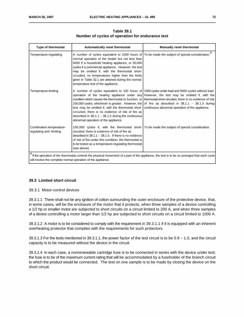
MARCH 26, 1997 ELECTRIC HEATING APPLIANCES – UL 499 72
Table 39.1Number of cycles of operation for endurance test
Type of thermostat Automatically reset thermostat Manually reset thermostat
Temperature-regulating A number of cycles equivalent to 1000 hours of To be made the subject of special consideration.normal operation of the heater but not less than6000 if a household heating appliance, or 30,000cycles if a commercial appliance. However, the testmay be omitted if, with the thermostat short-circuited, no temperatures higher than the limitsgiven in Table 32.1 are attained during the normal-temperature test of the appliance.
a
Temperature-limiting A number of cycles equivalent to 100 hours of 1000 cycles under load and 5000 cycles without load.operation of the heating appliance under any However, the test may be omitted if, with thecondition which causes the thermostat to function, or thermostat short-circuited, there is no evidence of risk100,000 cycles, whichever is greater. However, the of fire as described in 38.1.1 – 38.1.5 duringtest may be omitted if, with the thermostat short- continuous abnormal operation of the appliance.circuited, there is no evidence of risk of fire asdescribed in 38.1.1 – 38.1.5 during the continuousabnormal operation of the appliance.
Combination temperature- 100,000 cycles if, with the thermostat short- To be made the subject of special consideration.regulating and -limiting circuited, there is evidence of risk of fire as
described in 38.1.1 – 38.1.5. If there is no evidenceof risk of fire under this condition, the thermostat isto be tested as a temperature-regulating thermostat(see above).
If the operation of the thermostat controls the physical movement of a part of the appliance, the test is to be so arranged that each cyclea
will involve the complete normal operation of the appliance.
39.3 Limited short circuit
39.3.1 Motor-control devices
39.3.1.1 There shall not be any ignition of cotton surrounding the outer enclosure of the protective device, that,in some cases, will be the enclosure of the motor that it protects, when three samples of a device controllinga 1/2 hp or smaller motor are subjected to short circuits on a circuit limited to 200 A, and when three samplesof a device controlling a motor larger than 1/2 hp are subjected to short circuits on a circuit limited to 1000 A.
39.3.1.2 A motor is to be considered to comply with the requirement in 39.3.1.1 if it is equipped with an inherentoverheating protector that complies with the requirements for such protectors.
39.3.1.3 For the tests mentioned in 39.3.1.1, the power factor of the test circuit is to be 0.9 – 1.0, and the circuitcapacity is to be measured without the device in the circuit.
39.3.1.4 In each case, a nonrenewable cartridge fuse is to be connected in series with the device under test;the fuse is to be of the maximum current rating that will be accommodated by a fuseholder of the branch circuitto which the product would be connected. The test on one sample is to be made by closing the device on theshort circuit.
73 ELECTRIC HEATING APPLIANCES – UL 499 JULY 17, 1998
40 Strain Relief Test
40.1 The strain-relief means provided on an attached flexible cord, when tested in accordance with 40.2, shallbe capable of withstanding for 1 minute, without displacement, a pull of 35 lbf (156 N) applied to the cord, withthe connections within the product disconnected.
Exception: The cord on a soldering iron or wood-burning pencil having a mass of not more than 1/2 lb (0.227kg) exclusive of the cord shall withstand a pull of 20 lbf (89 N).
40.2 The strain relief means provided on leads as mentioned in the Exception to 10.1.1.5 when tested inaccordance with 40.3, shall be capable of withstanding for 1 minute without displacement a pull of 5 lbf (22 N)applied to the leads with connections at the termination disconnected.
40.3 The specified force is to be applied to the cord or leads, and the product so supported that the strain-reliefmeans will be stressed from any angle that the construction of the product permits. The strain-relief is notacceptable if, at the point of disconnection of the conductors, there is sufficient movement of the cord or leads,to indicate that stress on the connections would have resulted.
40A Push-Back Relief Test
*Added Section 40A effective July 16, 1999*
40A.1 To determine compliance with 10.2.2.3, a product shall be tested in accordance with 40A.2 withoutoccurrence of any of the following conditions:
a) The supply cord is subjected to mechanical damage;
b) The supply cord is exposed to a temperature higher than that for which it is rated;
c) Spacings, such as to a metal strain-relief clamp, are reduced below the minimum required values;or
d) Internal connections or components are damaged.
40A.2 The supply cord is to be held 1 inch (25.4 mm) from the point where the cord emerges from the productor cord bushing, when provided, and is then to be pushed back into the product. The cord is to be pushed backinto the product in 1 inch (25.4 mm) increments until the cord buckles or the force to push the cord into theproduct exceeds 6 pounds-force (26.7 N). The supply cord within the product is to be manipulated to determinecompliance with 40A.1.
41 Test for Permanence of Cord Tag for Outdoor-Use Heating Appliances with Power-Supply CordsLess than 6 Feet (1.8 m)
41.1 General
41.1.1 These tests are intended for tags employed with outdoor-use heating appliances requiring the markingof 45.33 with power-supply cords less than 6 ft (1.8 m), other than as mentioned in 45.14.
JULY 17, 1998 ELECTRIC HEATING APPLIANCES – UL 499 70A
41.1.2 To determine compliance with 45.34, representative samples that have been subjected to the testsdescribed in 41.1.4 – 41.1.7 shall meet the following requirements:
a) The tag shall resist tearing for longer than 1/16 inch (1.6 mm) at any point;
b) The tag shall not separate from the power-supply cord;
c) There shall be no permanent shrinkage, deformation, cracking, or any other condition that willrender the marking on the tag illegible; and
d) Overlamination shall remain in place and not be torn or otherwise damaged. The printing shallremain legible.
41.1.3 For each type of conditioning mentioned in 41.1.4 – 41.1.6, three samples of the tag applied to thepower-supply cord in the intended manner are to be used. If tags are applied by an adhesive, tests are to beconducted no sooner than 25 hours after application of the tag.
41.1.4 Three samples are to be tested as received.
41.1.5 Following conditioning in an air-circulating oven at 60 ±1EC (140 ±1.8EF) for 240 hours, three samplesare to be tested after 30 minutes of conditioning at a room temperature of 23 ±2EC (73.4 ±3.6EF) and 50 ±5percent relative humidity.
41.1.6 Three samples are to be tested within 1 minute after exposure for 72 hours to a humidity of 85 ±5percent at 32 ±2EC (89.6 ±3.6EF).
70B ELECTRIC HEATING APPLIANCES – UL 499 JULY 17, 1998
No Text on This Page
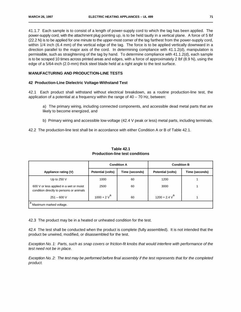
MARCH 26, 1997 ELECTRIC HEATING APPLIANCES – UL 499 71
41.1.7 Each sample is to consist of a length of power-supply cord to which the tag has been applied. Thepower-supply cord, with the attachment plug pointing up, is to be held tautly in a vertical plane. A force of 5 lbf(22.2 N) is to be applied for one minute to the upper-most corner of the tag farthest from the power-supply cord,within 1/4 inch (6.4 mm) of the vertical edge of the tag. The force is to be applied vertically downward in adirection parallel to the major axis of the cord. In determining compliance with 41.1.2(d), manipulation ispermissible, such as straightening of the tag by hand. To determine compliance with 41.1.2(d), each sampleis to be scraped 10 times across printed areas and edges, with a force of approximately 2 lbf (8.9 N), using theedge of a 5/64-inch (2.0-mm) thick steel blade held at a right angle to the test surface.
MANUFACTURING AND PRODUCTION-LINE TESTS
42 Production-Line Dielectric Voltage-Withstand Test
42.1 Each product shall withstand without electrical breakdown, as a routine production-line test, theapplication of a potential at a frequency within the range of 40 – 70 Hz, between:
a) The primary wiring, including connected components, and accessible dead metal parts that arelikely to become energized, and
b) Primary wiring and accessible low-voltage (42.4 V peak or less) metal parts, including terminals.
42.2 The production-line test shall be in accordance with either Condition A or B of Table 42.1.
Table 42.1Production-line test conditions
Appliance rating (V) Potential (volts) Time (seconds) Potential (volts) Time (seconds)
Condition A Condition B
Up to 250 V 1000 60 1200 1
600 V or less applied in a wet or moist 2500 60 3000 1condition directly to persons or animals
251 – 600 V 1000 + 2 V 60 1200 + 2.4 V 1a a
Maximum marked voltage.a
42.3 The product may be in a heated or unheated condition for the test.
42.4 The test shall be conducted when the product is complete (fully assembled). It is not intended that theproduct be unwired, modified, or disassembled for the test.
Exception No. 1: Parts, such as snap covers or friction-fit knobs that would interfere with performance of thetest need not be in place.
Exception No. 2: The test may be performed before final assembly if the test represents that for the completedproduct.
72 ELECTRIC HEATING APPLIANCES – UL 499 MARCH 26, 1997
42.5 When the product employs a solid-state component that is not relied upon to reduce the risk of electricshock and that can be damaged by the dielectric potential, the test may be conducted before the componentis electrically connected provided that a random sampling of each day's production is tested at the potentialspecified in Table 42.1. The circuitry may be rearranged for the purpose of the test to minimize the likelihoodof solid-state-component damage while retaining representative dielectric stress of the circuit.
42.6 The test equipment shall include a transformer having an essentially sinusoidal output, a means ofindicating the test potential, an audible or visual indicator of electrical breakdown, and either a manual-resetdevice to restore the equipment after electrical breakdown or an automatic-reject feature of any unacceptableunit.
42.7 If the output of the test-equipment transformer is less than 500 VA, the equipment shall include avoltmeter in the output circuit to directly indicate the test potential.
42.8 If the output of the test-equipment transformer is 500 VA or larger, the test potential may be indicated bya voltmeter in the primary circuit or in a tertiary-winding circuit, by a selector switch marked to indicate the testpotential, or, in the case of equipment having a single test-potential output, by a marking in a readily visiblelocation to indicate the test potential. When marking is used without an indicating voltmeter, the equipmentshall include a positive means, such as an indicator lamp, to indicate that the manual-reset switch has beenreset following a dielectric breakdown.
42.9 Test equipment, other than that described by 42.6 – 42.8, may be used if found to accomplish theintended factory control.
42.10 During the test a sufficient number of primary switching components shall be in the on position so thatall primary circuitry will be stressed. Both sides of the primary circuit of the product are to be connectedtogether and to one terminal of the test equipment, and the second test-equipment terminal is to be connectedto the accessible dead metal.
Exception: A product – resistive, high-impedance winding, and the like – having circuitry not subject toexcessive secondary-voltage build-up in case of electrical breakdown during the test may be tested:
a) With a single-pole primary switch, if used, in the off position; or
b) With only one side of the primary circuit connected to the test equipment when the primaryswitching components are in the on position, or when a primary switching component is not used.
43 Polarization and Grounding Continuity Tests
43.1 Continuity of grounding connection test
43.1.1 As a routine production-line test, each cord-connected appliance having a provision for grounding shallbe tested to determine grounding continuity between the grounding blade of the attachment plug and theaccessible metal parts of the appliance that are likely to become energized. See 43.3.1.

NOVEMBER 17, 1997 ELECTRIC HEATING APPLIANCES – UL 499 73
43.2 Polarization continuity test
43.2.1 As a routine production-line verification, each cord-connected heating appliance provided with a 2-wirepolarized or 3-wire grounding attachment plug shall be examined or tested for electrical continuity between theungrounded circuit supply conductor of the attachment plug (see Figure 10.1 for attachment plug bladeconnections) and all components intended to be connected to the ungrounded conductor. If the continuitycannot be readily determined by visual inspection and component checking, an electrical continuity test is tobe conducted. See 43.3.1.
43.3 Electrical indicating device
43.3.1 Any indicating device (an ohmmeter, a battery-and-buzzer combination, or the like) may be used todetermine compliance with the continuity requirements in 43.1.1 and 43.2.1.
RATINGS
44 Details
44.1 A heating appliance shall be rated in amperes, volt-amperes, or watts, and also in volts, and may be ratedfor alternating current only. The rating shall include the number of phases if the product is constructed for useon a polyphase circuit, and shall include the frequency if necessary because of motors, relay coils, or othercontrol devices. The voltage rating shall be in accordance with any appropriate single voltage or range ofvoltages, such as 100 – 120, 208, 220 – 240, 254 – 277, 416, 440 – 480, 550, 575, and 600.
44.2 A heating appliance having provision for permanent connection to the electrical supply and incorporatinga motor load of more than 1/20 hp shall also be marked in accordance with 45.2.
44.3 When a heating appliance includes an attachment-plug receptacle that is not intended as a disconnectingmeans for any part of the product or necessary accessory, and that serves as a general-use outlet, the addedload that the receptacle imposes on the product and its supply connections – not less than 660 W or 6 A – shallbe taken into consideration in determining the electrical rating of the product.
*44.3 revised November 17, 1997*
44.4 A liquid-heating appliance in which live parts are in contact with the liquid shall be rated for alternatingcurrent only.
44.5 The rating of a liquid-heating appliance of the immersed-electrode type may include a current or wattagerange to indicate the general variations that may be anticipated when the product is used with water of differentconductivity.
MARKINGS
45 Details
45.1 A heating appliance shall be permanently marked where it will be plainly visible – after installation in thecase of a permanently connected product – with the manufacturer's name, trade name, trademark, or otherdescriptive marking by which the organization responsible for the product may be identified, the catalog numberor the equivalent, and the electrical ratings. A product intended for use on alternating current only or directcurrent only shall be so marked.
74 ELECTRIC HEATING APPLIANCES – UL 499 MARCH 26, 1997
45.2 A heating appliance constructed as described in 44.2 shall also be marked with the motor load inamperes and volts.
45.3 If a manufacturer produces or assembles heating appliances at more than one factory, each finishedproduct shall have a distinctive marking – which may be in code – by which it may be identified as the productof a particular factory.
45.4 Each individual heating element or unit that is a part of a heating appliance and that is replaceable in thefield shall be plainly marked with its electrical ratings in amperes or watts, and also in volts, or with themanufacturer's part number.
45.5 A heating appliance whose acceptable performance depends upon its proper location or position shallbe marked – such as "top" and "bottom" – to indicate the way in which it is to be installed or used, unless suchposition is obvious.
45.6 If the design of a heating appliance contemplates disassembly by means of a tool for the purpose ofcleaning or similar servicing by the user, including replacement of a thermal cutoff, and, if such disassemblyinvolves the exposure of persons to unintentional contact with any usually enclosed or protected live part, theproduct shall be plainly marked with a warning that such servicing should be done only while the product isdisconnected from the supply circuit. See also 6.17.
45.7 If any point within a terminal box or wiring compartment of a permanently connected heating appliancein which field-installed conductors are intended to be connected, including such conductors themselves, attainsa temperature higher than 60EC (140EF) during the normal-temperature test, the product shall be legiblymarked "For supply connections use ___ AWG or larger wires suitable for at least ___EC (___EF)" or with anequivalent statement. The temperature value shall be in accordance with Table 45.1. The wire size need notbe included if No. 14 AWG (0.21 mm ) wire was used during the test. This wording shall be located at or near2
the point where the supply connections are to be made and shall be clearly visible during installation andexamination of the supply-wiring connections.
Table 45.1Temperature for marking
Temperature attained in terminal box or compartment during test Temperature marking
61 – 75EC (142 – 167EF) 75EC (167EF)
76 – 90EC (169 – 194EF) 90EC (194EF)
45.8 The outlet box provided with an immersion heater intended for use in water shall be marked inaccordance with 45.7.
MARCH 26, 1997 ELECTRIC HEATING APPLIANCES – UL 499 75
45.9 If a specific spacing between a heating appliance intended to be either permanently connected electricallyor fastened in place or located in a dedicated space and an adjacent surface is necessary to limit thetemperature to not more than 90EC (194EF) on the latter when the product is operated as intended, the productshall be marked "Do not install closer than ___ inches (or ___ mm) to a (vertical, horizontal, or other) surface."The value of the spacing to be used in the statement shall not be less than that necessary to limit thetemperature to not more than 90EC (194EF) on the walls when the product is tested in the corner describedin 32.1.17. The statement shall be legible and so located where clearly visible during installation andexamination of the supply-wiring connections for products intended to be permanently connected electricallyand during and after installation for products intended to be fastened in place or located in a dedicated space.
45.10 A cord-connected heating appliance that is required to have provision for grounding through the cordand plug in accordance with 26.6 shall be plainly marked "CAUTION" and the following or the equivalentstatement, "To provide continued protection against risk of electric shock, connect to properly grounded outletsonly."
45.11 Each heating appliance provided with a 2-wire polarized attachment plug shall be provided with thefollowing instructions or the equivalent: "This appliance has a polarized plug (one blade is wider than the other).To reduce the risk of electric shock, this plug is intended to fit in a polarized outlet only one way. If the plugdoes not fit fully in the outlet, reverse the plug. If it still does not fit, contact a qualified electrician. Do not modifythe plug in any way."
45.12 A household heating appliance or a commercial soldering station provided with a power-supply cord,attached or detachable, that is less than 4-1/2 ft (1.4 m) in length as described in 10.2.1.1, shall be providedwith instructions in accordance with 45.13.
45.13 The instructions required in 45.12 are to include the following information:
a) A short power-supply cord (or short detachable power-supply cord) is provided to reduce the risksresulting from becoming entangled in or tripping over a longer cord.
b) Extension cords (or longer detachable power-supply cords) are available and may be used if careis exercised in their use.
c) If an extension cord (or a long detachable power-supply cord) is used:
1) The marked electrical rating of the detachable power-supply cord or extension cord shouldbe at least as great as the electrical rating of the appliance,
2) If the appliance is of the grounded type, the extension cord should be a grounding-type 3-wire cord, and
3) The longer cord should be arranged so that it will not drape over the countertop or tabletopwhere it can be tripped over, snagged, or pulled on unintentionally (especially by children).
45.14 A stock-tank water heater, bucket heater, de-icer, and similar type product that is used out of doors andis provided with a power-supply cord, shall be marked with the signal word "WARNING" and the following orthe equivalent statement, "Store indoors after winter season. Inspect cord before using. Do not use extensioncords. Read all instructions."
76 ELECTRIC HEATING APPLIANCES – UL 499 MARCH 26, 1997
45.15 The instructions mentioned in 45.14 shall include a paragraph stating "CAUTION" and the following orequivalent statement, "To provide continued protection against electric shock:
a) Have a qualified electrician install a properly grounded receptacle outlet, acceptable for outdooruse and protected from snow and rain, immediately adjacent to the location where the heater will beused,
b) Route the supply cord and locate the heater so as to be protected from damage by live stock,
c) Do not use extension cords,
d) Inspect cord before using,
e) Unplug heater at receptacle outlet when not in use or before removing from tank, and
f) Store heater indoors after winter season."
45.16 Heating appliances intended for outdoor use with power-supply cords less than 6 ft (1.8 m), other thanas mentioned in 45.14, shall be provided with instructions that include 45.13 (b) and (c) and the followinginformation:
a) Outdoor extension cords should be used with outdoor use products and are surface marked withsuffix letter "W-A" and with a tag stating "Suitable for Use with Outdoor Appliances".
b) A statement indicating that the connection to an extension cord should be kept dry and off theground.
c) Store product indoors when not in use – out of the reach of children.
d) Do not clean this product with a water spray or the like. (This statement may be omitted if theresults of a special water hose spray test are acceptable.)
45.17 If the normal-temperature test of a ceramics-baking oven (kiln) is concluded when the internaltemperature of the oven has reached a specified value as described in 32.2.2.1, the oven shall have a legiblemarking, that will be readily visible to the operator after the product has been installed as intended, warning thatthe power supply to the product should be cut off when the temperature of the interior reaches the specifiedvalue.
45.18 An insecticide vaporizer shall be provided with a warning statement, either as a marking on the productitself or included in an instruction booklet packed with the product, cautioning the user that there may be dangerif toxic materials are dispensed in a kitchen where there is uncovered food, or in occupied sleeping quarters.
45.19 A heating appliance of the type that can be expected to be immersed in water for cleaning purposesshall be marked "Do not immerse in water" or with an equivalent wording, unless the product has beeninvestigated for water immersion in accordance with 32.1.4 and 33.11. If the product is intended for partialimmersion but not for complete immersion, it shall be marked "Do not immerse beyond this point" or with anequivalent wording to show the point beyond that it should not be immersed.
MARCH 26, 1997 ELECTRIC HEATING APPLIANCES – UL 499 77
45.20 If the normal-temperature test of a poultry or livestock brooder is conducted with the product mountedat a greater height above the supporting surface than the minimum permitted by its construction, the productshall be marked to indicate that it should be mounted at such height or higher for operation. This marking shallbe legible, permanent in character, and so located as to be visible.
45.21 If the guard of a poultry or livestock brooder is removed for shipment, the product shall be marked witha visible, legible marking cautioning against using the product unless the guard is in place.
45.22 A heating appliance that is intended for installation by a nonmetal-enclosed wiring system only shall bemarked to indicate that it must be installed with such a wiring system. The marking shall be so located that itwill be visible while power-supply connections to the product are being made.
45.23 A product having provision for permanent connection to multiple power supplies shall bear a cautionarymarking to indicate that fact. The marking shall be on the outside of the product where visible after installationof the product. The marking shall be made at each point at which a power-supply connection is to be made.The product shall be marked with the word "CAUTION" and the following or the equivalent statement, "Thisproduct has more than one power-supply connection point. Disconnect all power supplies before servicing."
45.24 A product that is intended for use with a thermostatically controlled appliance plug shall be permanentlymarked "Use only (manufacturer) (designation) temperature-controlling plug" or with an equivalent wording.
45.25 A product intended for use with a power source as described in 10.2.1.14 and 10.2.1.15 shall be legiblymarked with the following or an equivalent statement, "(Name and model number of the product) for use withpower source number ___." A power source intended for use with a product as described in 10.2.1.14 and10.2.1.15 shall be legibly marked with the following or an equivalent statement, "Power source for use with only(name and model number of the product)."
45.26 If required overcurrent protective devices or contactors are provided as a separate assembly, see 17.7and 24.6, the product shall be marked to indicate that it is to be used only with this separate assembly.
45.27 A drying heater that is intended for paint drying in auto repair and paint shops shall be permanentlymarked with the following statement, "DANGER – To reduce the risk of explosion, do not use in paint spraybooths or within 10 feet of paint spraying operations." The marking shall be readily visible after the heater isin the position of intended use. This marking or the equivalent shall also appear in the operating and direction-for-use instructions.
45.28 A product that is to be installed or used in conformity with provisions of the National Electrical Code andwhere there may be some question to the installer or user, shall be provided with information, which may bein the form of a description marked on or provided with the product, to identify the acceptability of the productfor the specific application, purpose, or environment.
45.29 A refrigerator defroster shall be permanently and legibly marked where visible to the user with the word"CAUTION" and the following or the equivalent statement, "To reduce risk of fire, do not operate unattended;use with care on or near plastic surfaces." The word "CAUTION" shall be in uppercase letters not less than1/8 inch (3.2 mm) high, and the remaining letters in the marking shall not be less than 1/16 inch (1.6 mm) high.

78 ELECTRIC HEATING APPLIANCES – UL 499 MARCH 26, 1997
45.30 A heat gun shall be marked with the word "WARNING" and the following or the equivalent: "To reducethe risk of fire or electric shock, do not expose this product to rain or moisture. Store indoors. Read instructionmanual before using." The marking shall be permanent. The signal word WARNING shall be printed in uppercase letters or emphasized to distinguish it from the rest of the text and shall be not less than 3/32 inch (2.4mm) high. The remainder of the text shall be in letters not less than 1/16 inch (1.6 mm) high if the letters havea contrasting color to the background. Letters that are molded or stamped in a material not having acontrasting background color shall have a height of not less than 3/32 inch (2.4 mm) and raised or lowereddepth of not less than 0.020 inch (0.51 mm).
Exception: The marking specified in 45.30 need not be provided if the heat gun is marked "FOR INDOOR USEONLY" or with an equivalent wording. The marking shall be permanent, in a color contrasting with thebackground, or if molded or stamped raised or lowered for not less than 0.020 inch (0.51 mm) and in lettersno less than 3/32 inch (2.4 mm) high.
45.31 The instruction manual for a heat gun shall include the following or equivalent statements:
a) "Hidden areas such as behind walls, ceilings, floors, soffit boards and other panels may containflammable materials that could be ignited by the heat gun when working in these locations. Theignition of these materials may not be readily apparent and could result in property damage and injuryto persons.
When working in these locations, keep the heat gun moving in a back-and-forth motion. Lingering orpausing in one spot could ignite the panel or the material behind it."
b) "IMPORTANT SAFETY INSTRUCTIONS
READ THESE INSTRUCTIONS
WARNING: Extreme care should be taken when stripping paint. The peelings, residue and vaporsof paint may contain lead, which is poisonous. Any pre-1977 paint may contain lead and paint appliedto homes prior to 1950 is likely to contain lead. Once deposited on surfaces, hand to mouth contactcan result in the ingestion of lead. Exposure to even low levels of lead can cause irreversible brain andnervous system damage; young and unborn children are particularly vulnerable.
Before beginning any paint removal process you should determine whether the paint you are removingcontains lead. This can be done by your local health department or by a professional who uses a paintanalyzer to check the lead content of the paint to be removed. LEAD-BASED PAINT SHOULD ONLYBE REMOVED BY A PROFESSIONAL AND SHOULD NOT BE REMOVED USING A HEAT GUN.
Persons removing paint should follow these guidelines:
1) Move the work piece outdoors. If this is not possible, keep the work area well ventilated.Open the windows and put an exhaust fan in one of them. Be sure the fan is moving the airfrom inside to outside.
2) Remove or cover any carpets, rugs, furniture, clothing, cooking utensils and air ducts.
3) Place drop cloths in the work area to catch any paint chips or peelings. Wear protectiveclothing such as extra work shirts, overalls and hats.

MARCH 26, 1997 ELECTRIC HEATING APPLIANCES – UL 499 79
4) Work in one room at a time. Furnishings should be removed or placed in the center of theroom and covered. Work areas should be sealed off from the rest of the dwelling by sealingdoorways with drop cloths.
5) Children, pregnant or potentially pregnant women and nursing mothers should not bepresent in the work area until the work is done and all clean up is complete.
6) Wear a dust respirator mask or a dual filter (dust and fume) respirator mask which hasbeen approved by the Occupational Safety and Health Administration (OSHA), the NationalInstitute of Safety and Health (NIOSH), or the United States Bureau of Mines. These masksand replaceable filters are readily available at major hardware stores. Be sure the mask fits.Beards and facial hair may keep masks from sealing properly. Change filters often.DISPOSABLE PAPER MASKS ARE NOT ADEQUATE.
7) Use caution when operating the heat gun. Keep the heat gun moving as excessive heatwill generate fumes which can be inhaled by the operator.
8) Keep food and drink out of the work area. Wash hands, arms and face and rinse mouthbefore eating or drinking. Do not smoke or chew gum or tobacco in the work area.
9) Clean up all removed paint and dust by wet mopping the floors. Use a wet cloth to cleanall walls, sills and any other surface where paint or dust is clinging. DO NOT SWEEP, DRYDUST OR VACUUM. Use a high phosphate detergent or trisodium phosphate (TSP) to washand mop areas.
10) At the end of each work session put the paint chips and debris in a double plastic bag,close it with tape or twist ties and dispose of properly.
11) Remove protective clothing and work shoes in the work area to avoid carrying dust intothe rest of the dwelling. Wash work clothes separately. Wipe shoes off with a wet rag that isthen washed with the work clothes. Wash hair and body thoroughly with soap and water.
SAVE THESE INSTRUCTIONS"
Exception: The instructions in (b) need not be included in the instruction manual if the heat gunexhaust barrel is so constructed that the heat gun cannot be used to strip paint.
45.32 The marking provided on an electrically energized product that generates steam shall be clearly marked"Not for Space Heating Purposes" or equivalent wording. The product, carton, and literature marking shall notrefer to the steam generator as a "boiler".
45.33 A cord-connected outdoor-use heating appliance with a power-supply cord less than 6 ft (1.8 m), otherthan as mentioned in 45.14, shall be marked: "CAUTION – To reduce the risk of electric shock, keep extensioncord connection dry and off the ground", or with an equivalent wording following the word "CAUTION".
45.34 The marking described in 45.33 may be provided on a tag that is permanently attached to the power-supply cord. The tag material and means of attachment to the power-supply cord shall comply with therequirements in Test for Permanence of Cord Tag for Outdoor-Use Heating Appliances with Power-SupplyCords Less than 6 Feet (1.8 m), Section 41. The tag and the printing thereon shall be resistant to water.
80 ELECTRIC HEATING APPLIANCES – UL 499 MARCH 26, 1997
45.35 An appliance whose surface temperatures exceed the limits specified in Table 32.2, (see 28.3), shallbe marked with the word "CAUTION" and the following or equivalent wording: "Hot Surface. Avoid Contact."The marking shall be located on or adjacent to the surface in question.
45.36 A product that passes water through a filter media before consumption shall be marked, either on theproduct or in the instruction booklet provided, with the following or equivalent: "The physiological effects of theoperation of this appliance, beneficial or otherwise, have not been investigated by__________________________ (Name, or abbreviation of name, of organization that investigated theappliance for compliance with this Standard)".
45.37 Steam generating products provided with multiple vessels shall be permanently marked adjacent toeach steam outlet "DANGER" followed by the following or equivalent: "To Reduce Risk of Explosion, Do NotInterconnect Steam Outlets. A Separate Steam Line Must be Provided for Each Steam Outlet."
46 Instructions
46.1 A product that requires warning, cautionary, or other specific markings as indicated in Markings, Details,Section 45 shall be provided with instructions that duplicate the texts of the required markings and elaborateon the potential risks involved.
Exception: The information specified in 45.1 and 45.2 need not be provided in the instruction booklet.
ELECTRODE-TYPE HEATING APPLIANCES
47 Scope
47.1 These requirements cover portable electrode-type heating appliances intended for household use thatare constructed to be employed on nominal 120-V branch circuits. It does not cover electrode-type cosmeticproducts, except for accessories that may be provided with a heating appliances.
48 General
48.1 In addition to complying with Sections 49 – 55, the products shall comply with all applicable requirementsin this Standard.
49 Construction
49.1 A facial sauna attachment for use with a multipurpose electrode-type heating appliance shall include aguard, barrier assembly or an equivalent means to restrict the emission of hot water droplets into the facial areaof the product during intended use. The barrier assembly shall be constructed of materials acceptable for andmounted in the manner required for the enclosure of live parts.
49.2 The interposed barrier assembly may consist of two or more layers arranged to provide a baffle effect forall openings.
MARCH 26, 1997 ELECTRIC HEATING APPLIANCES – UL 499 81
50 Operation Test
50.1 An electrode-type heating appliance with a facial sauna attachment when subjected to the operation testin 50.2, shall be such that:
a) There is neither appreciable distortion nor any cracking of any of its parts,
b) There is no evidence of arcing or tracking over the surface or through insulating material,
c) There is no evidence of glowing or flaming,
d) There is no spitting of water in the area where the user's face may be located, and
e) No more than five fuses are opened by a single product.
50.2 Three samples assembled as for intended use are to be subjected to the following test. A test solutionof 4 g/L of sodium chloride (NaCl) in distilled water is to be prepared. The product is to be connected to a 150-V a-c supply through a 20-A time-delay fuse and filled to the intended fill level from a nonconducting containerwith the test solution. After the current has reduced to an average value of less than 20 percent of ratedcurrent, the unit is to remain connected to the supply for an additional 10 minutes. Without emptying orcleaning, the unit is then to be filled to the fill level with distilled, deionized, or tap water having a resistivitygreater than 20,000 ohm-centimeters. The cycling is to be continued for a total of 30 complete cycles. Afterthe 30th cycle, the unit is to be de-energized and filled with tap water and then emptied. The preceding stepsare then to be repeated nine times starting with the filling using the saline test solution, to obtain 300 cycles ofoperation. In cases where there is loss of solution salt, sodium chloride is to be added to the distilled, deionized,or tap water so that the operating portion of a cycle does not exceed 300 percent of the time consumed by theinitial operating cycle. If the fuse blows at any time during the test, the product is to be emptied and filled withtap water, allowed to stand for 5 seconds and then emptied. The unit is then to be filled with the test solutionand the test continued. In each filling care is to be taken to fill only to the recommended fill level and not tooverfill the samples.
50.3 An electrode-type heating appliance other than mentioned in 50.1 and 51.1, when subjected to theoperation test in 50.4, shall be such that:
a) There is neither distortion nor any cracking of any of its parts,
b) There is no evidence of arcing or tracking over the surface or through insulating material,
c) There is no evidence of glowing or flaming,
d) There is no continuous spitting of water beyond the outer perimeter of the product, and
e) Not more than three fuses are opened by a single product.
50.4 Three samples are to be subjected to the test indicated in 50.2 except that the test solution is to be 3 g/Lof sodium chloride in distilled water.
82 ELECTRIC HEATING APPLIANCES – UL 499 MARCH 26, 1997
51 Vaporizer-Operation Test
51.1 An electrode-type vaporizer when subjected to the operation test in 51.2 shall be such that:
a) There is neither appreciable distortion nor any cracking of any of its parts,
b) There is no evidence of arcing or tracking over the surface or through insulating material,
c) There is no evidence of glowing or flaming,
d) There is no continuous spitting of water more than 6 inches (152 mm) from the outer perimeter ofthe vaporizer when measured on the supporting surface, and
e) Not more than three fuses are opened by a single product.
51.2 Three samples are to be subjected to the following test. A test solution of 2 g/L of sodium chloride (NaCl)in distilled water is to be prepared. The product is to be connected to a 150-V a-c supply through a 20-A time-delay fuse and filled to the intended level from a nonconducting container with the test solution. After thecurrent has reduced to an average value of less than 20 percent of rated current, the unit is to remainconnected to the supply for an additional hour. Without emptying or cleaning, the unit is then to be filled to thefilled level with distilled, deionized, or tap water having a resistivity greater than 20,000 ohm-centimeters. Thecycling is to be continued for a total of five complete cycles. After the fifth cycle, the unit is to be de-energized.The electrode unit is then to be removed and immersed up to the full mark in tap water. The upper and loweropenings are to be covered and the unit inverted once. The electrode unit is then to be righted and the waterallowed to drain through the lower hole. The reservoir is to be rinsed thoroughly with tap water. The electrodeunit is to be reinserted and the unit refilled with the sodium chloride solution. This procedure is to be repeatednine times for a total of 50 operating cycles. If the fuse opens at any time during the test, the electrode unit andreservoir are to be rinsed as described above and the product refilled with the sodium chloride solution.
52 Leakage Current Test
52.1 A vaporizer shall be constructed so that when filled to the "filled" level mark with a hard water solution of0.5 gram of calcium sulfate (CaSO @2H O) per liter of distilled water, the leakage current measured at any point4 2that can be contacted by the articulate probe in Figure 6.2 does not exceed 0.5 mA. The vaporizer shall beoperated normally (assembled) or with the electrode unit or any part such as a fill cap moved to any possibleposition that can be maintained unattended and still provide for normal operation. The fill cap may be left inits normal (closed) position if marked in accordance with 54.2(c). See 52.9.
52.2 A vaporizer shall not present a risk of electric shock when the electrode unit and its housing (if removablewithout the use of tools) is partially removed from the hard-water solution. The vaporizer shall be consideredto involve a risk of electric shock if the current from any point, including the hard solution, when contacted bythe probe specified in 52.1 is more than 5 mA, when measured through a 500-ohm resistor. The current shallbe measured with the vaporizer connected to the normal supply circuit. The current shall be measured againwith reverse polarity of the supply circuit.
52.3 During the test covered in 52.2, a reservoir, the material of which has not been found acceptable for theintended application, is to be disregarded and the measurement taken directly from the hard-water solution bylocating the electrode unit in any position of operation, or whatever other means may be necessary.
MARCH 26, 1997 ELECTRIC HEATING APPLIANCES – UL 499 83
52.4 An electrode-type appliance other than a vaporizer shall be constructed so that with the applianceassembled and filled for use in its intended manner, there are no openings in the enclosure or guard whichwould permit contact with the energized water by use of:
a) The articulate probe illustrated in Figure 6.2 or the rod illustrated in Figure 6.4 and
b) As judged by the requirements in 6.13 and 6.15.
52.5 The leakage current available from accessible surfaces (including those moistened by the liquid) of anelectrode type heating appliance other than a vaporizer under any intended condition of operation shall not begreater than 0.5 mA when the unit is operated with a hard-water solution made as described in 52.1. In thecase of a bottle warmer, a bottle completely wrapped in metal foil is to be placed in the product. See 52.9.
52.6 During the tests covered in 52.4, 52.5 and 52.7, a guard or enclosure the material of which has not beenfound acceptable for the particular application is to be removed.
52.7 An electrode-type appliance other than a vaporizer shall have a leakage current not exceeding 0.5 mAwhen measured under conditions described in (a) and (b):
a) The water container of an appliance at room temperature is to be filled with a volume of the hardwater solution – made as specified in 52.1 – equal to 150 percent of the maximum intended amountrecommended by the manufacturer. The leakage current to ground is to be measured with the unitoperating while tipped in any direction and at any angle not exceeding 30 degrees from its normaloperating position to cause maximum leakage current. The probe employed in the measurement shallbe a copper alloy rod with an insulated handle. The rod is to be:
1) Sized to represent the probe in Figure 6.2 or 6.4 and
2) Applied as determined by 6.13 and 6.15. See 52.9.
b) The test in (a) is to be repeated, except that the appliance is to be mounted in its normal operatingposition and filled with twice the maximum volume of the specified hard-water solution.
52.8 If the appliance is provided with a polarized attachment plug, the current measured as described in 52.7shall not exceed 0.5 mA with the plug inserted in the receptacle either in the intended position, or with thepolarity reversed.
52.9 During the tests outlined in 52.1 – 52.8:
a) The supply voltage is to be 120 V, and
b) The leakage current is to be measured as described in 31.1 – 31.7, except that the leakage currentis to be continuously monitored until it stabilizes or decreases.
53 Disassembly and Reassembly Test
53.1 If the instructions involve disassembly of any parts for cleaning, it shall be determined that the unit isunlikely to be reassembled in a manner that will result in a risk of fire, electric shock, or injury to persons.
84 ELECTRIC HEATING APPLIANCES – UL 499 MARCH 26, 1997
54 Markings
54.1 An electrode-type vaporizer employing Type STP-1, SP-1, SPT-2, or SP-2 No. 18 AWG (0.82 mm )2
supply cord shall have a permanent warning marking consisting of the word "CAUTION" and the following orequivalent statement, "This unit's supply cord may overheat and involve a risk of fire unless cord is unraveledin use."
54.2 The product shall be marked with the following:
a) A filled level marking that can easily be compared to the actual water level during filling, or if otherthan a vaporizer, with instructions for the use of an integral measuring container or other measuringmeans for filling. If the measuring container is not integral with the product, the amount shall beexpressed in standard measurements in addition to the use of any measuring container provided.
b) Instructions for filling, cleaning, and rinsing the unit and any instructions for additives to be used.
c) The word "CAUTION" and the following or equivalent statement, "To provide continued protectionagainst the risk of electric shock:
1) Disconnect the supply cord before filling, rinsing, or cleaning.
2) Do not fill above the filled level mark" (or (2) "Do not fill with more than ___ cups of water").
In case of a fill cap mentioned in 52.1, the marking shall appear at the fill opening.
54.3 An electrode-type heating appliance employed for warming or cooking foods – such as bottle warmers,egg cookers, and the like – shall be marked with word "CAUTION" and the following or equivalent statement,"For protection against the risk of electric shock, do not put metal containers or utensils in this appliance."
54.4 A vaporizer shall be marked with the word "CAUTION" and the following or the equivalent statement, "Toprovide continued protection against excessive reservoir water temperatures that may cause burns on upsettingunit, follow instructions on filling, cleaning, and rinsing."
54.5 Unless a facial steamer (sauna) attachment meets the requirements of 49.1 and 50.1, it shall be markedwith the word "CAUTION" and the following or equivalent statement, "This product may cause burns fromspraying of hot water from unit unless rinsed and cleaned in accordance with the instructions."
54.6 Cautionary markings and instructions shall be permanent and legible and shall be located on a part thatcannot be removed without impairing the operation of the product.
54.7 Cautionary marking and instructions intended to instruct the operator shall be legible and clearly visibleto the operator during use of the product. Other such markings for servicing instructions should be legible andclearly visible when such servicing is being accomplished.
MARCH 26, 1997 ELECTRIC HEATING APPLIANCES – UL 499 85
54.8 Markings intended to warn against a risk of injury to persons shall be prefixed by the word "CAUTION"in letters not less than 3/32 inch (2.4 mm) high.
54.9 A marking that is required to be permanent shall be molded, die-stamped, paint-stenciled, stamped oretched on metal, indelibly stamped lettering, or a pressure-sensitive label secured by adhesive that isacceptable for the particular application (see 56.1 – 56.7). Usage, handling, storage, and the like, of theproduct will be considered in the determination of the permanence of the marking.
55 Operating Instructions
55.1 Operating instructions shall be provided with the product that include the following:
a) Information regarding potential risks of fire, electric shock, or injury to persons that may exist dueto use of the product. The instructions shall caution the user to place the product and connected cordso that the product is not likely to be upset.
b) Information regarding the potential risks of electric shock due to overfilling or cleaning the productand removal of the heating element portion of the vaporizer without disconnecting the power-supplycord.
c) Instructions regarding cleaning the product including any need for disassembly (and reassembly)and any need for the use of additives.
56 Label Adhesion Tests
56.1 Pressure sensitive labels or labels secured by cement or adhesive which have been subjected to the testsoutlined in 56.2 – 56.7 shall meet the following conditions:
a) Each label shall demonstrate good adhesion and the edges shall not be curled.
b) The label shall resist defacement or removal as demonstrated by scraping across the test panelwith a flat metal blade 1/32 inch (0.8 mm) thick, held at a right angle to the test panel.
c) The printing shall be legible and shall not be defaced by rubbing with thumb or finger pressure.
56.2 For each of the four types of conditioning mentioned in 56.3 and 56.5 – 56.7, three samples of the labelare to be applied to the same test surface employed in the intended application. The labels are to be appliedto the test surface no less than 24 hours prior to testing.
56.3 Three samples of the labels are to be evaluated as received.
56.4 Evaluation of samples is to be made at the end of each test as indicated in 56.5 – 56.7:
a) Immediately following removal from each test medium, and
b) After exposure to room temperature for 24 hours following removal from each test medium.
56.5 Three samples of the labels under test are to be placed in a full-draft circulating-air oven maintained atthe temperature indicated in Table 56.1 for 240 hours.
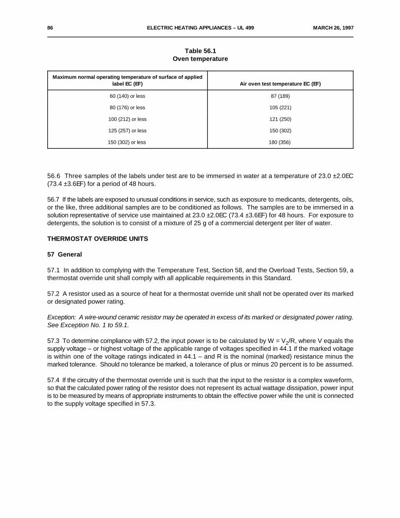
86 ELECTRIC HEATING APPLIANCES – UL 499 MARCH 26, 1997
Table 56.1Oven temperature
Maximum normal operating temperature of surface of appliedlabel EC (EF) Air oven test temperature EC (EF)
60 (140) or less 87 (189)
80 (176) or less 105 (221)
100 (212) or less 121 (250)
125 (257) or less 150 (302)
150 (302) or less 180 (356)
56.6 Three samples of the labels under test are to be immersed in water at a temperature of 23.0 ±2.0EC(73.4 ±3.6EF) for a period of 48 hours.
56.7 If the labels are exposed to unusual conditions in service, such as exposure to medicants, detergents, oils,or the like, three additional samples are to be conditioned as follows. The samples are to be immersed in asolution representative of service use maintained at 23.0 ±2.0EC (73.4 ±3.6EF) for 48 hours. For exposure todetergents, the solution is to consist of a mixture of 25 g of a commercial detergent per liter of water.
THERMOSTAT OVERRIDE UNITS
57 General
57.1 In addition to complying with the Temperature Test, Section 58, and the Overload Tests, Section 59, athermostat override unit shall comply with all applicable requirements in this Standard.
57.2 A resistor used as a source of heat for a thermostat override unit shall not be operated over its markedor designated power rating.
Exception: A wire-wound ceramic resistor may be operated in excess of its marked or designated power rating.See Exception No. 1 to 59.1.
57.3 To determine compliance with 57.2, the input power is to be calculated by W = V /R, where V equals the2supply voltage – or highest voltage of the applicable range of voltages specified in 44.1 if the marked voltageis within one of the voltage ratings indicated in 44.1 – and R is the nominal (marked) resistance minus themarked tolerance. Should no tolerance be marked, a tolerance of plus or minus 20 percent is to be assumed.
57.4 If the circuitry of the thermostat override unit is such that the input to the resistor is a complex waveform,so that the calculated power rating of the resistor does not represent its actual wattage dissipation, power inputis to be measured by means of appropriate instruments to obtain the effective power while the unit is connectedto the supply voltage specified in 57.3.
MARCH 26, 1997 ELECTRIC HEATING APPLIANCES – UL 499 87
58 Temperature Test
58.1 Unless the resistor is securely positioned to prevent it from contacting polymeric enclosure material, thepolymeric material shall be acceptable for the maximum temperature measured on the resistor body underintended operating conditions.
Exception: The temperature rating of the polymeric material may be less than the maximum temperaturemeasured on the resistor during the normal temperature test if five samples of the thermostat override unit areoperated for 1000 hours with the resistor in contact with or as close as possible to the polymeric enclosurematerial. There shall be no undue distortion, melting or ignition of the enclosure.
58.2 A resistor is considered to be securely positioned if its mounting means provides a reasonable degree ofresistance to shifting or motion during rough handling including dropping three samples, three times each, ontoa hardwood surface from a height of 3 ft (0.9 m), and during manipulation of the supply cord in any direction.Suspension of the resistor by only its integral pigtail leads is not considered to be securely positioned unlessit can be demonstrated that spacing to the enclosure can be consistently maintained during production.
59 Overload Tests
59.1 Units that utilize a resistor as a heat source shall be subjected to the following overload tests.
Exception No. 1: A wire-wound ceramic resistor may be considered for exclusion from 59.2 – 59.5 whenoperated not in excess of its marked or designated power rating.
Exception No. 2: Other types of resistors may be considered for exclusion from 59.2 – 59.5 if their reliabilityof performance has been demonstrated for the service conditions encountered in the end-use application –percent wattage dissipation and surface temperature. Evidence that the resistors comply with the applicablesections of Military Specification MIL-R-39008, "Resistors, Fixed, Composition (Insulated), EstablishedReliability", and have a failure-rate designation "R" (failure-rate of 0.01 percent per 1000 hours), would beregarded as demonstration of reliability of performance.
59.2 Five samples of a thermostat override unit, that have been operated for 1000 hours under intendedoperating conditions, shall each be mounted on a vertical surface that is covered with a double layer of whitetissue paper. A horizontal 3/8 inch (9.5 mm) thick, minimum 1 ft (0.3 m) deep and minimum 2 ft (0.6 m) wideplywood surface is to be mounted 12 inches (305 mm) below the thermostat override unit to simulate mountingdirectly above a bookcase or desk. The horizontal 3/8 inch (9.5 mm) plywood is to be covered with a doublelayer of cheesecloth. A 3 by 2 by 6 inches (76 by 51 by 152 mm) box simulating a room thermostat enclosure,constructed of 3/8 inch thick plywood, covered with a double layer of cheesecloth is to be mounted above thethermostat override unit at the minimum distance recommended in the installation instructions. The longestdimension of the box is to be parallel with the top of the thermostat override unit enclosure. If no minimumspacing is indicated, the thermostat override unit shall be mounted as close as possible to the simulatedthermostat test box, see Figure 59.1 for details.
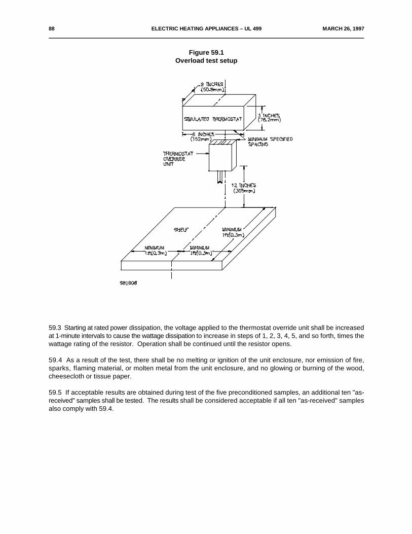
88 ELECTRIC HEATING APPLIANCES – UL 499 MARCH 26, 1997
Figure 59.1Overload test setup
59.3 Starting at rated power dissipation, the voltage applied to the thermostat override unit shall be increasedat 1-minute intervals to cause the wattage dissipation to increase in steps of 1, 2, 3, 4, 5, and so forth, times thewattage rating of the resistor. Operation shall be continued until the resistor opens.
59.4 As a result of the test, there shall be no melting or ignition of the unit enclosure, nor emission of fire,sparks, flaming material, or molten metal from the unit enclosure, and no glowing or burning of the wood,cheesecloth or tissue paper.
59.5 If acceptable results are obtained during test of the five preconditioned samples, an additional ten "as-received" samples shall be tested. The results shall be considered acceptable if all ten "as-received" samplesalso comply with 59.4.
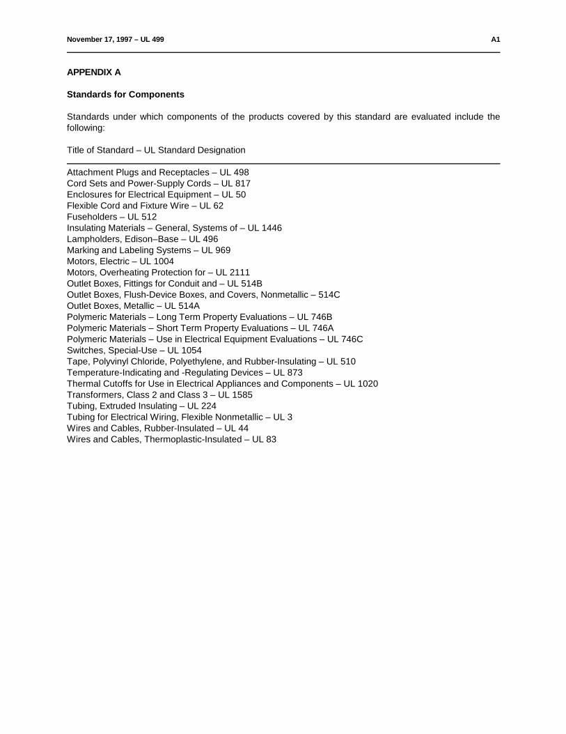
November 17, 1997 – UL 499 A1
APPENDIX A
Standards for Components
Standards under which components of the products covered by this standard are evaluated include thefollowing:
Title of Standard – UL Standard Designation
Attachment Plugs and Receptacles – UL 498Cord Sets and Power-Supply Cords – UL 817Enclosures for Electrical Equipment – UL 50Flexible Cord and Fixture Wire – UL 62Fuseholders – UL 512Insulating Materials – General, Systems of – UL 1446Lampholders, Edison–Base – UL 496Marking and Labeling Systems – UL 969Motors, Electric – UL 1004Motors, Overheating Protection for – UL 2111 Outlet Boxes, Fittings for Conduit and – UL 514BOutlet Boxes, Flush-Device Boxes, and Covers, Nonmetallic – 514COutlet Boxes, Metallic – UL 514APolymeric Materials – Long Term Property Evaluations – UL 746BPolymeric Materials – Short Term Property Evaluations – UL 746APolymeric Materials – Use in Electrical Equipment Evaluations – UL 746CSwitches, Special-Use – UL 1054Tape, Polyvinyl Chloride, Polyethylene, and Rubber-Insulating – UL 510Temperature-Indicating and -Regulating Devices – UL 873Thermal Cutoffs for Use in Electrical Appliances and Components – UL 1020Transformers, Class 2 and Class 3 – UL 1585Tubing, Extruded Insulating – UL 224Tubing for Electrical Wiring, Flexible Nonmetallic – UL 3Wires and Cables, Rubber-Insulated – UL 44Wires and Cables, Thermoplastic-Insulated – UL 83
A2 March 26, 1997 – UL 499
No Text on This Page
July 17, 1998 – UL 499 sr1
Superseded requirements for
the Standard for
Electric Heating Appliances
UL 499, Twelfth Edition
The requirements shown are the current requirements that have been superseded by requirements in revisionsissued for this Standard. To retain the current requirements, do not discard the following requirements untilthe future effective dates are reached.
10.2.2.3 Means shall be provided to restrict an attached power supply cord from being pushed into theenclosure of a product through the cord-entry hole if such displacement is likely to subject the cord tomechanical damage or to expose the cord to a temperature higher than that for which it is acceptable, or if itis likely to reduce spacings, such as to a metal strain-relief clamp, below the minimum acceptable values.
sr2 July 17, 1998 – UL 499
No Text on This Page