Embed Size (px)
Citation preview
Operating, Maintenance &Parts Manual
20900
SLC Series
The use of any hoist presents some risk of personal injuryor property damage. That risk is greatly increased if properinstructions and warnings are not followed. Before usingthis hoist, each operator should become thoroughly familiarwith all warnings, instructions, and recommendations in thismanual. Retain this manual for future reference and use.
Forward this manual to the hoist operator.Failure to operate the equipment as directed in the manualmay cause injury.
Should you have any questions or have problems with thisproduct, please refer to pages 20 and 21.
Follow all instructions and warnings forinspecting, maintaining and operating this hoist.
Ele
ctri
c Chain
Capacities
250 lbs (113 kg) 300 lbs (136 kg)500 lbs (226 kg) 600 lbs (272 kg)
1,000 lbs (453 kg)
Before using the hoist, fill in the information below. Refer to thehoist identification plate.
Model Number
Serial Number
Purchase Date
Voltage
SAFETY PRECAUTIONS
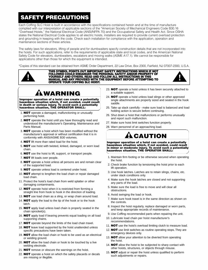
1. NOT operate a damaged, malfunctioning or unusually performing hoist.
2. NOT operate the hoist until you have thoroughly read andunderstood the manufacturer’s Operating, Maintenance andParts Manual.
3. NOT operate a hoist which has been modified without themanufacturer’s approval or without certification that it is inconformity with ANSI/ASME B30 volumes.
4. NOT lift more than rated load for the hoist.
5. NOT use hoist with twisted, kinked, damaged, or worn loadchain.
6. NOT use the hoist to lift, support, or transport people.
7. NOT lift loads over people.
8. NOT operate a hoist unless all persons are and remain clearof the supported load.
9. NOT operate unless load is centered under hoist.
10. NOT attempt to lengthen the load chain or repair damaged load chain.
11. Protect the hoist’s load chain from weld splatter or otherdamaging contaminants.
12. NOT operate hoist when it is restricted from forming astraight line from hook to hook in the direction of loading.
13. NOT use load chain as a sling, or wrap chain around load.
14. NOT apply the load to the tip of the hook or to the hooklatch.
15. NOT apply load unless load chain is properly seated in the chain sprocket(s).
16. NOT apply load if bearing prevents equal loading on all loadsupporting chains.
17. NOT operate beyond the limits of the load chain travel.
18. NOT leave load supported by the hoist unattended unlessspecific precautions have been taken.
19. NOT allow the load chain or hook to be used as an electricalor welding ground.
20. NOT allow the load chain or hook to be touched by a live welding electrode.
21. NOT remove or obscure the warnings on the hoist.
22. NOT operate a hoist on which the safety placards or decalsare missing or illegible.
23. NOT operate a hoist unless it has been securely attached toa suitable support.
24. NOT operate a hoist unless load slings or other approvedsingle attachments are properly sized and seated in the hooksaddle.
25. Take up slack carefully - make sure load is balanced and loadholding action is secure before continuing.
26. Shut down a hoist that malfunctions or performs unusuallyand report such malfunction.
27. Make sure hoist limit switches function properly.
28. Warn personnel of an approaching load.
1. Maintain firm footing or be otherwise secured when operating the hoist.
2. Check brake function by tensioning the hoist prior to each lift operation.
3. Use hook latches. Latches are to retain slings, chains, etc.under slack conditions only.
4. Make sure the hook latches are closed and not supportingany parts of the load.
5. Make sure the load is free to move and will clear allobstructions.
6. Avoid swinging the load or hook.
7. Make sure hook travel is in the same direction as shown on the controls.
8. Inspect the hoist regularly, replace damaged or worn parts,and keep appropriate records of maintenance.
9. Use Coffing recommended parts when repairing the unit.
10. Lubricate load chain per hoist manufacturer’srecommendations.
11. NOT use the hoist’s overload limiting clutch to measure load.
12. NOT use limit switches as routine operating stops. They areemergency devices only.
13. NOT allow your attention to be diverted from operating the hoist.
14. NOT allow the hoist to be subjected to sharp contact withother hoists, structures, or objects through misuse.
15. NOT adjust or repair the hoist unless qualified to performsuch adjustments or repairs.
Improper operation of a hoist can create a potentiallyhazardous situation which, if not avoided, could resultin death or serious injury. To avoid such a potentiallyhazardous situation, THE OPERATOR SHALL:
Improper operation of a hoist can create a potentiallyhazardous situation which, if not avoided, could resultin minor or moderate injury. To avoid such a potentiallyhazardous situation, THE OPERATOR SHALL:
Each Coffing SLC Hoist is built in accordance with the specifications contained herein and at the time of manufacturecomplied with our interpretation of applicable sections of the *American Society of Mechanical Engineers Code B30.16“Overhead Hoists,” the National Electrical Code (ANSI/NFPA 70) and the Occupational Safety and Health Act. Since OSHAstates the National Electrical Code applies to all electric hoists, installers are required to provide current overload protectionand grounding in keeping with the code. Check each installation for compliance with the application, operation andmaintenance sections of these articles.
The safety laws for elevators, lifting of people and for dumbwaiters specify construction details that are not incorporated intothe hoists. For such applications, refer to the requirements of applicable state and local codes, and the American NationalSafety Code for elevators, dumbwaiters, escalators and moving walks (ASME A17.1). We cannot be responsible forapplications other than those for which the equipment is intended.
*Copies of this standard can be obtained from ASME Order Department, 22 Law Drive, Box 2300, Fairfield, NJ 07007-2300, U.S.A.
THIS SYMBOL POINTS OUT IMPORTANT SAFETY INSTRUCTIONS WHICH IF NOT FOLLOWED COULD ENDANGER THE PERSONAL SAFETY AND/OR PROPERTY OF YOURSELF AND OTHERS. READ AND FOLLOW ALL INSTRUCTIONS IN THIS MANUAL AND ANY PROVIDED WITH THE EQUIPMENT BEFORE ATTEMPTING TO OPERATE YOUR COFFING SLC HOIST.
1
REPAIR/REPLACEMENT POLICYAll SLC Hoists are inspected and performance tested priorto shipment. If any properly maintained hoist develops aperformance problem, due to a material or workmanshipdefect, as verified by Coffing Hoists, repair or replacementof the unit will be made to the original purchaser withoutcharge. This repair/replacement policy applies only to SLCHoists installed, maintained and operated as outlined in thismanual, and specifically excludes hoists subject to normalwear, abuse, improper installation, improper or inadequatemaintenance, hostile environmental effects and unauthorizedrepairs/modifications.
We reserve the right to change materials or design if, in ouropinion, such changes will improve our product. Abuse,repair by an unauthorized person, or use of non-originalreplacement parts voids the guarantee and could lead todangerous operation. For full Terms of Sale, see Sales OrderAcknowledgment. Also, refer to the back cover forLimitations of Warranties, Remedies and Damages, andIndemnification and Safe Operation.
ACCESSORIESChain Container
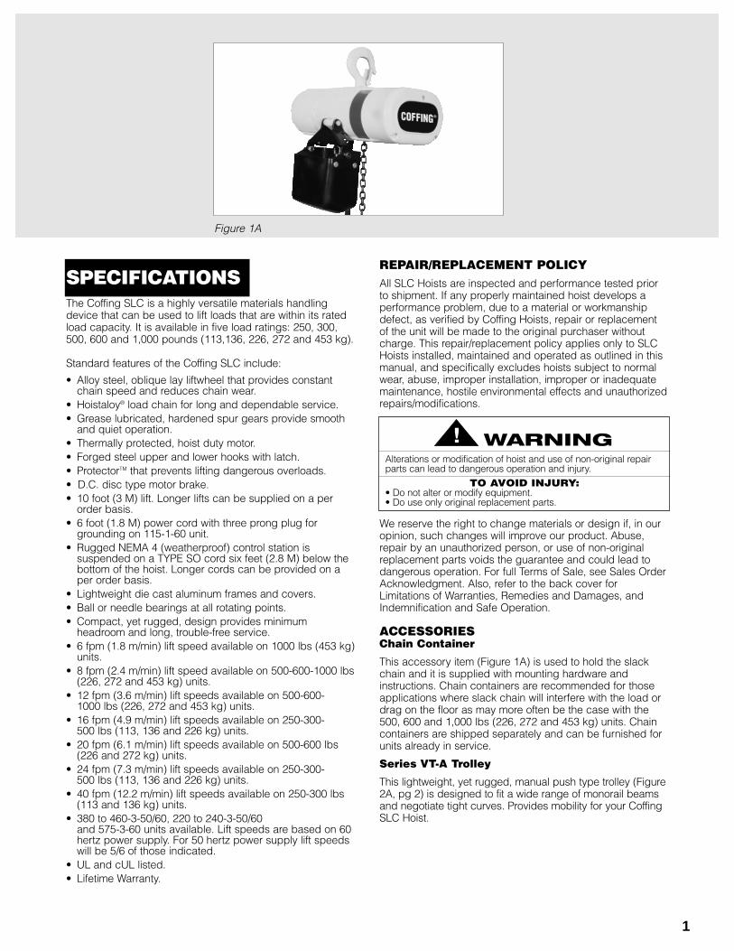
This accessory item (Figure 1A) is used to hold the slackchain and it is supplied with mounting hardware andinstructions. Chain containers are recommended for thoseapplications where slack chain will interfere with the load ordrag on the floor as may more often be the case with the500, 600 and 1,000 lbs (226, 272 and 453 kg) units. Chaincontainers are shipped separately and can be furnished forunits already in service.
Series VT-A Trolley
This lightweight, yet rugged, manual push type trolley (Figure2A, pg 2) is designed to fit a wide range of monorail beamsand negotiate tight curves. Provides mobility for your CoffingSLC Hoist.
The Coffing SLC is a highly versatile materials handlingdevice that can be used to lift loads that are within its ratedload capacity. It is available in five load ratings: 250, 300,500, 600 and 1,000 pounds (113,136, 226, 272 and 453 kg).
Standard features of the Coffing SLC include:
• Alloy steel, oblique lay liftwheel that provides constantchain speed and reduces chain wear.
• Hoistaloy® load chain for long and dependable service.• Grease lubricated, hardened spur gears provide smooth
and quiet operation.• Thermally protected, hoist duty motor.• Forged steel upper and lower hooks with latch.• ProtectorTM that prevents lifting dangerous overloads.• D.C. disc type motor brake.• 10 foot (3 M) lift. Longer lifts can be supplied on a per
order basis.• 6 foot (1.8 M) power cord with three prong plug for
grounding on 115-1-60 unit. • Rugged NEMA 4 (weatherproof) control station is
suspended on a TYPE SO cord six feet (2.8 M) below thebottom of the hoist. Longer cords can be provided on aper order basis.
• Lightweight die cast aluminum frames and covers.• Ball or needle bearings at all rotating points.• Compact, yet rugged, design provides minimum
headroom and long, trouble-free service. • 6 fpm (1.8 m/min) lift speed available on 1000 lbs (453 kg)
units.• 8 fpm (2.4 m/min) lift speed available on 500-600-1000 lbs
(226, 272 and 453 kg) units. • 12 fpm (3.6 m/min) lift speeds available on 500-600-
1000 lbs (226, 272 and 453 kg) units.• 16 fpm (4.9 m/min) lift speeds available on 250-300-
500 lbs (113, 136 and 226 kg) units.• 20 fpm (6.1 m/min) lift speeds available on 500-600 lbs
(226 and 272 kg) units.• 24 fpm (7.3 m/min) lift speeds available on 250-300-
500 lbs (113, 136 and 226 kg) units.• 40 fpm (12.2 m/min) lift speeds available on 250-300 lbs
(113 and 136 kg) units.• 380 to 460-3-50/60, 220 to 240-3-50/60
and 575-3-60 units available. Lift speeds are based on 60hertz power supply. For 50 hertz power supply lift speedswill be 5/6 of those indicated.
• UL and cUL listed.• Lifetime Warranty.
Figure 1A
Alterations or modification of hoist and use of non-original repairparts can lead to dangerous operation and injury.
TO AVOID INJURY:• Do not alter or modify equipment.• Do use only original replacement parts.
SPECIFICATIONS
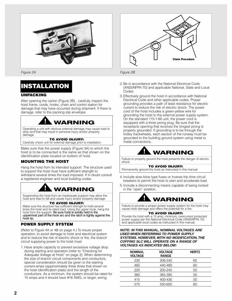
UNPACKINGAfter opening the carton (Figure 2B) , carefully inspect thehoist frame, cords, hooks, chain and control station fordamage that may have occurred during shipment. If there isdamage, refer to the packing slip envelope.
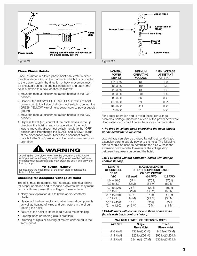
Make sure that the power supply (Figure 3A) to which thehoist is to be connected is the same as that shown on theidentification plate located on bottom of hoist.
MOUNTING THE HOISTHang the hoist from its intended support. The structure usedto support the hoist must have sufficient strength towithstand several times the load imposed. If in doubt consulta registered engineer and local building codes.
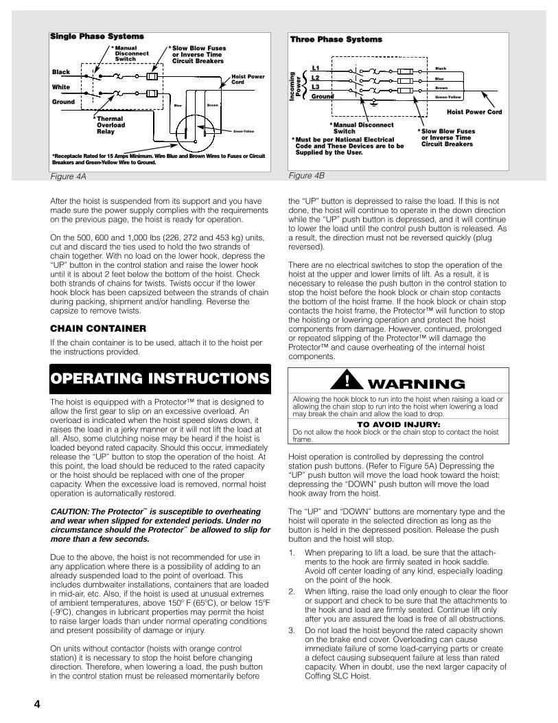
POWER SUPPLY SYSTEM(Refer to Figure 4A or 4B on page 4.) To insure properoperation, to avoid damage to hoist and electrical systemand to reduce the risk of electric shock or fire, the branchcircuit supplying power to the hoist must:
1. Have ample capacity to prevent excessive voltage dropduring starting and operation (refer to “Checking forAdequate Voltage at Hoist” on page 3). When determiningthe size of branch circuit components and conductors,special consideration should be given to the startingcurrent-amps (approximately three times that shown onthe hoist identification plate) and the length of theconductors. As a minimum, the system should be rated for15 amps and it should have #16 AWG, or larger, wiring.
2
Operating a unit with obvious external damage may cause load todrop and that may result in personal injury and/or propertydamage.
TO AVOID INJURY:Carefully check unit for external damage prior to installation.
Figure 2A Figure 2B
Claim Procedure
2. Be in accordance with the National Electrical Code(ANSI/NFPA-70) and applicable National, State and LocalCodes.
3. Effectively ground the hoist in accordance with NationalElectrical Code and other applicable codes. Propergrounding provides a path of least resistance for electriccurrent to reduce the risk of electric shock. The powercord of the hoist includes a green-yellow wire forgrounding the hoist to the external power supply system.On the standard 115-1-60 unit, the power cord isequipped with a three prong plug. Be sure that thereceptacle opening that receives the longest prong isproperly grounded. If grounding is to be through thetrolley trackwheels, each section of the runway must begrounded to the building ground system using metal tometal connections.
4. Include slow blow type fuses or inverse trip time circuitbreakers to permit the hoist to start and accelerate load.
5. Include a disconnecting means capable of being lockedin the “open” position.
NOTE: IN THIS MANUAL, NOMINAL VOLTAGES AREUSED WHEN REFERRING TO POWER SUPPLYSYSTEMS. HOWEVER, WITH NO MODIFICATION, THECOFFING SLC WILL OPERATE ON A RANGE OFVOLTAGES AS INDICATED BELOW:
NOMINAL VOLTAGE HERTZVOLTAGE RANGE
230 208-240 60460 440-480 60220 200-240 50380 365-395 50415 400-430 50575 550-600 60
Suspending the hoist from an inadequate support may allow thehoist and load to fall and cause injury and/or property damage.
TO AVOID INJURY:Make sure the structure has sufficient strength to hold severaltimes the hoist and its rated load. Using the upper hook, hang thehoist from the support. BBee ssuurree hhooiisstt iiss ssoolliiddllyy hheelldd iinn tthheeuuppppeerrmmoosstt ppaarrtt ooff tthhee hhooookk aarrcc aanndd tthhee llaattcchh iiss ttiigghhttllyy aaggaaiinnsstt tthheehhooookk ttiipp..
Failure to properly ground the hoist presents the danger of electricshock.
TO AVOID INJURY:Permanently ground the hoist as instructed in this manual.
INSTALLATION
Failure to provide a proper power supply system for the hoist maycause hoist damage and offers the potential for a fire.
TO AVOID INJURY:Provide the hoist with a 15 amp, minimum, overcurrent protectedpower supply per the National Electrical Code (ANSI/NFPA 70)and applicable local codes as instructed in this manual.
3
Figure 3A Figure 3B
Power supply
Same
Making sure the hoist will operate onthe power supply system
Nameplate
Three Phase Hoists
Since the motor in a three phase hoist can rotate in eitherdirection, depending on the manner in which it is connectedto the power supply, the direction of hook movement mustbe checked during the original installation and each timehoist is moved to a new location as follows:
1. Move the manual disconnect switch handle to the “OFF”position.
2. Connect the BROWN, BLUE AND BLACK wires of hoistpower cord to load side of disconnect switch. Connect theGREEN-YELLOW wire of hoist power cord to power supplyground.
3. Move the manual disconnect switch handle to the “ON”position.
4. Depress the � (up) control. If the hook moves in the updirection, the hoist is ready for operation. If the hooklowers, move the disconnect switch handle to the “OFF”position and interchange the BLACK and BROWN leadsat the disconnect switch. Move the disconnect switchhandle to the “ON” position and the hoist is now ready foroperation.
Checking for Adequate Voltage at Hoist
The hoist must be supplied with adequate electrical powerfor proper operation and to reduce problems that may resultfrom insufficient power (low voltage). These include:
• Noisy hoist operation due to brake and/or contactorchatter.
• Heating of the hoist motor and other internal componentsas well as heating of wires and connectors in the circuitfeeding the hoist.
• Failure of the hoist to lift the load due to motor stalling.• Blowing fuses or tripping circuit breakers.• Dimming of lights or slowing of motors connected to the
same circuit.
NOMINAL MINIMUM * MIN. VOLTAGEPOWER OPERATING AT INSTANTSUPPLY VOLTAGE OF START115-1-60 108 103208-3-60 187 172220-3-50 198 182230-3-60 207 190380-3-50 365 336415-3-50 399 367460-3-60 414 380575-3-60 518 506
For proper operation and to avoid these low voltageproblems, voltage (measured at end of the power cord whilelifting rated load) should be as the above chart indicates.
*The drop in voltage upon energizing the hoist shouldnot be below the value listed.
Low voltage can also be caused by using an undersizedextension cord to supply power to the hoist. The followingcharts should be used to determine the size wires in theextension cord in order to minimize the voltage dropbetween the power source and the hoist.
115-1-60 units without contactor (hoists with orangecontrol station)
LENGTH MAXIMUM LENGTH OF CONTROL OF EXTENSION CORD BASED
CORD ON SIZE OF WIREft(M) #16 AWG #14 AWG #12 AWG
1.0 to 10.0 105 ft 170 ft 270 ft(0.3 to 3.0) (32 M) (51 M) (82 M)10.1 to 20.0 75 ft 120 ft 190 ft(3.1 to 6.0) (22 M) (36 M) (58 M)20.1 to 30.0 45 ft 70 ft 110 ft(6.1 to 9.0) (14 M) (21 M) (33 M)30.1 to 40.0 15 ft 20 ft 35 ft(9.1 to 12.0) (4.5 M) (6 M) (11 M)
115-1-60 units with contactor and three phase units(hoists with black control station).
MAXIMUM LENGTH OF EXTENSION CORDWire Size Single Three
Phase Hoist Phase Hoist#16 AWG 135 feet(40 M) 245 feet(73 M)#14 AWG 220 feet(66 M) 395 feet(120 M)#12 AWG 354 feet(107 M) 630 feet(192 M)
Allowing the hook block to run into the bottom of the hoist whenraising a load or allowing the chain stop to run into the bottom ofthe hoist when lowering a load may break the chain and allow theload to drop.
TO AVOID INJURY:Do not allow the hook block or the chain stop to contact thebottom of the hoist.
COFFING
Upper Hook
Loose End ofChain
Chain Stop
ControlStation
Lower Hook
Power Cord
4
Hoist PowerCord
Green-Yellow
* Manual Disconnect Switch
Black
White
Ground
*Slow Blow Fusesor Inverse Time Circuit Breakers
*Thermal OverloadRelay
*Receptacle Rated for 15 Amps Minimum. Wire Blue and Brown Wires to Fuses or CircuitBreakers and Green-Yellow Wire to Ground.
BrownBlue
Hoist Power Cord
*Slow Blow Fusesor Inverse Time Circuit Breakers
*Must be per National Electrical Code and These Devices are to be Supplied by the User.
*Manual Disconnect Switch
Black
Blue
Brown
Green-Yellow
TThhrreeee PPhhaassee SSyysstteemmss
L1L2L3GroundIn
com
ing
Pow
er
Figure 4A Figure 4B
After the hoist is suspended from its support and you havemade sure the power supply complies with the requirementson the previous page, the hoist is ready for operation.
On the 500, 600 and 1,000 lbs (226, 272 and 453 kg) units,cut and discard the ties used to hold the two strands ofchain together. With no load on the lower hook, depress the“UP” button in the control station and raise the lower hookuntil it is about 2 feet below the bottom of the hoist. Checkboth strands of chains for twists. Twists occur if the lowerhook block has been capsized between the strands of chainduring packing, shipment and/or handling. Reverse thecapsize to remove twists.
CHAIN CONTAINERIf the chain container is to be used, attach it to the hoist perthe instructions provided.
The hoist is equipped with a Protector™ that is designed toallow the first gear to slip on an excessive overload. Anoverload is indicated when the hoist speed slows down, itraises the load in a jerky manner or it will not lift the load atall. Also, some clutching noise may be heard if the hoist isloaded beyond rated capacity. Should this occur, immediatelyrelease the “UP” button to stop the operation of the hoist. Atthis point, the load should be reduced to the rated capacityor the hoist should be replaced with one of the propercapacity. When the excessive load is removed, normal hoistoperation is automatically restored.
CAUTION: The Protector™ is susceptible to overheatingand wear when slipped for extended periods. Under nocircumstance should the Protector™ be allowed to slip formore than a few seconds.
Due to the above, the hoist is not recommended for use inany application where there is a possibility of adding to analready suspended load to the point of overload. Thisincludes dumbwaiter installations, containers that are loadedin mid-air, etc. Also, if the hoist is used at unusual extremesof ambient temperatures, above 150º F (65ºC), or below 15ºF(-9ºC), changes in lubricant properties may permit the hoistto raise larger loads than under normal operating conditionsand present possibility of damage or injury.
On units without contactor (hoists with orange controlstation) it is necessary to stop the hoist before changingdirection. Therefore, when lowering a load, the push buttonin the control station must be released momentarily before
the “UP” button is depressed to raise the load. If this is notdone, the hoist will continue to operate in the down directionwhile the “UP” push button is depressed, and it will continueto lower the load until the control push button is released. Asa result, the direction must not be reversed quickly (plugreversed).
There are no electrical switches to stop the operation of thehoist at the upper and lower limits of lift. As a result, it isnecessary to release the push button in the control station tostop the hoist before the hook block or chain stop contactsthe bottom of the hoist frame. If the hook block or chain stopcontacts the hoist frame, the Protector™ will function to stopthe hoisting or lowering operation and protect the hoistcomponents from damage. However, continued, prolongedor repeated slipping of the Protector™ will damage theProtector™ and cause overheating of the internal hoistcomponents.
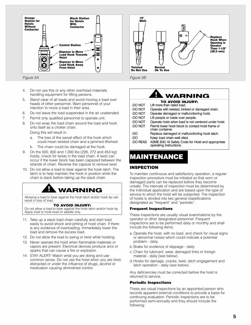
Hoist operation is controlled by depressing the controlstation push buttons. (Refer to Figure 5A) Depressing the“UP” push button will move the load hook toward the hoist;depressing the “DOWN” push button will move the loadhook away from the hoist.
The “UP” and “DOWN” buttons are momentary type and thehoist will operate in the selected direction as long as thebutton is held in the depressed position. Release the pushbutton and the hoist will stop.
1. When preparing to lift a load, be sure that the attach-ments to the hook are firmly seated in hook saddle.Avoid off center loading of any kind, especially loadingon the point of the hook.
2. When lifting, raise the load only enough to clear the flooror support and check to be sure that the attachments tothe hook and load are firmly seated. Continue lift onlyafter you are assured the load is free of all obstructions.
3. Do not load the hoist beyond the rated capacity shownon the brake end cover. Overloading can causeimmediate failure of some load-carrying parts or createa defect causing subsequent failure at less than ratedcapacity. When in doubt, use the next larger capacity ofCoffing SLC Hoist.
Allowing the hook block to run into the hoist when raising a load orallowing the chain stop to run into the hoist when lowering a loadmay break the chain and allow the load to drop.
TO AVOID INJURY:Do not allow the hook block or the chain stop to contact the hoistframe.
OPERATING INSTRUCTIONS
SSiinnggllee PPhhaassee SSyysstteemmss
INSPECTIONTo maintain continuous and satisfactory operation, a regularinspection procedure must be initiated so that worn ordamaged parts can be replaced before they becomeunsafe. The intervals of inspection must be determined bythe individual application and are based upon the type ofservice to which the hoist will be subjected. The inspectionof hoists is divided into two general classificationsdesignated as “frequent” and “periodic”.
Frequent Inspections
These inspections are usually visual examinations by theoperator or other designated personnel. Frequentinspections are to be performed daily or monthly and shallinclude the following items:
a. Operate the hoist, with no load, and check for visual signsor abnormal noises which could indicate a potentialproblem - daily.
b.Brake for evidence of slippage - daily.c. Chain for lubricant, wear, damaged links or foreign
material - daily (see below).d.Hooks for damage, cracks, twist, latch engagement and
latch operation - daily (see below).
Any deficiencies must be corrected before the hoist isreturned to service.
Periodic Inspections
These are visual inspections by an appointed person whorecords apparent external conditions to provide a basis forcontinuing evaluation. Periodic inspections are to beperformed semi-annually and they should include thefollowing:
5
4. Do not use this or any other overhead materialshandling equipment for lifting persons.
5. Stand clear of all loads and avoid moving a load overheads of other personnel. Warn personnel of yourintention to move a load in their area.
6. Do not leave the load suspended in the air unattended.7. Permit only qualified personnel to operate unit.8. Do not wrap the load chain around the load and hook
onto itself as a choker chain.Doing this will result in:a. The loss of the swivel effect of the hook which
could mean twisted chain and a jammed liftwheel.b. The chain could be damaged at the hook.
9. On the 500, 600 and 1,000 lbs (226, 272 and 453 kg)hoists, check for twists in the load chain. A twist canoccur if the lower block has been capsized between thestrands of chain. Reverse the capsize to remove twist.
10. Do not allow a load to bear against the hook latch. Thelatch is to help maintain the hook in position while thechain is slack before taking up the slack chain.
11. Take up a slack load chain carefully and start loadeasily to avoid shock and jerking of hoist chain. If thereis any evidence of overloading, immediately lower theload and remove the excess load.
12. Do not allow the load to swing or twist while hoisting.13. Never operate the hoist when flammable materials or
vapors are present. Electrical devices produce arcs orsparks that can cause a fire or explosion.
14. STAY ALERT! Watch what you are doing and usecommon sense. Do not use the hoist when you are tired,distracted or under the influence of drugs, alcohol ormedication causing diminished control.
Allowing a load to bear against the hook latch and/or hook tip canresult in loss of load.
TO AVOID INJURY:Do not allow a load to bear against the hook latch and/or hook tip.Apply load to hook bowl or saddle only.
Figure 5A Figure 5B
TO AVOID INJURY:--DDOO NNOOTT LLiifftt mmoorree tthhaann rraatteedd llooaadd..--DDOO NNOOTT OOppeerraattee wwiitthh ttwwiisstteedd,, kkiinnkkeedd oorr ddaammaaggeedd cchhaaiinn..--DDOO NNOOTT OOppeerraattee ddaammaaggeedd oorr mmaallffuunnccttiioonniinngg hhooiisstt..--DDOO NNOOTT LLiifftt ppeeooppllee oorr llooaaddss oovveerr ppeeooppllee.. --DDOO NNOOTT OOppeerraattee hhooiisstt wwhheenn llooaadd iiss nnoott cceenntteerreedd uunnddeerr hhooiisstt..--DDOO NNOOTT PPeerrmmiitt lloowweerr hhooookk bblloocckk ttoo ccoonnttaacctt hhooiisstt ffrraammee oorr
cchhaaiinn ccoonnttaaiinneerr..--DDOO RReeppllaaccee ddaammaaggeedd oorr mmaallffuunnccttiioonniinngg hhooookk llaattcchh..--DDOO KKeeeepp llooaadd cchhaaiinn wweellll ooiilleedd..--DDOO RREEAADD AASSMMEE BB3300..1166 SSaaffeettyy CCooddee ffoorr HHooiisstt aanndd aapppprroopprriiaattee
ooppeerraattiinngg iinnssttrruuccttiioonnss..
ReplaceHook WhenOpening isGreaterThan 1-1/8"(28.5 mm)
Normal Ok To Use
TwistedDo Not Use
10°MAX.
UP
DOWN
OrangeStation forHoistsWithoutContactor
Black Stationfor HoistsWith Contactor
Control Station
Depress to MoveLoad Hook TowardsHoist Depress to MoveLoad Hook AwayFrom Hoist
MAINTENANCE
6
Figure 6A Figure 6B
a. All items listed under frequent inspections.b.External evidence of loose screws.c. External evidence of worn, corroded, cracked or distorted
hook block, gears, bearings, chain stop and hook retainer.d.External evidence of damage or excessive wear of the
liftwheel or sheave (double reeved unit). Widening anddeepening of pockets may cause chain to lift-up in thepockets and cause binding between liftwheel and chainguide or between lower sheave and hook block. Checkchain guide for wear or burring where the chain enters thehoist. Severely worn or damaged parts should bereplaced.
e. External evidence of excessive wear of brake parts - seepage 8.
f. Check the control station push buttons to make sure theyoperate freely and spring back when released.
g.Check power cord, control cord and control station fordamaged insulation.
h. Check for pitting and any deterioration of contactorcontacts (hoists with black control station).
i. Check the chain pin or dead end pin and chain stop forwear and cracks.
j. Check for lubricant leaks at gasket between main frameand gear housing. Tighten gear housing screws to stopleak. If leak persists, replace gasket.
k. Inspect splines on first pinion shaft and motor coupling forsigns of wear or deterioration. Replace splined parts ifworn or damaged.
NOTE: To perform some of the periodic inspections, it isnecessary to partially disassemble the hoist. Refer toDisassembly - Assembly starting on page 12.
Any deficiencies noted must be corrected before the hoist isreturned to service. Also, the external conditions may showthe need for more detailed inspection which, in turn, mayrequire the use of nondestructive-type testing.
Any parts that are deemed unserviceable are to be replacedwith new parts before the unit is returned to service. It is veryimportant that the unserviceable parts be destroyed toprevent possible future use as a repair item and properlydisposed of.
Hook Inspection
Hooks damaged from chemicals, deformations or cracks orthat have more than a 10° twist from the plane of the unbenthook or excessive opening must be replaced.
Any hook that is twisted or has excessive throat openingindicates abuse or overloading of the unit. Other load-sustaining components of the hoist should be inspected fordamage.
On latch type hooks, check to make sure that the latch is notdamaged or bent and that it operates properly with sufficientspring pressure to keep the latch tightly against the tip of thehook and allow the latch to spring back to the tip whenreleased. If the latch does not operate properly. It should bereplaced. See Figure 5B, pg. 5 to determine when the hookmust be replaced.
LOAD CHAINChain should feed smoothly into and away from the hoist orhook block (500, 600 and 1,000 lbs, 226, 272 and 453 kgunits). If chain binds, jumps or is noisy, first clean andlubricate it (see below). If trouble persists, inspect chain andmating parts for wear, distortion or other damage.
Chain Inspection
First clean chain with a non-caustic/non-acid type solventand make a link by link inspection for nicks, gouges, twistedlinks, weld spatter, corrosion pits, striations (minute parallellines), cracks in weld areas, wear and stretching. Chain withany one of these defects must be replaced.
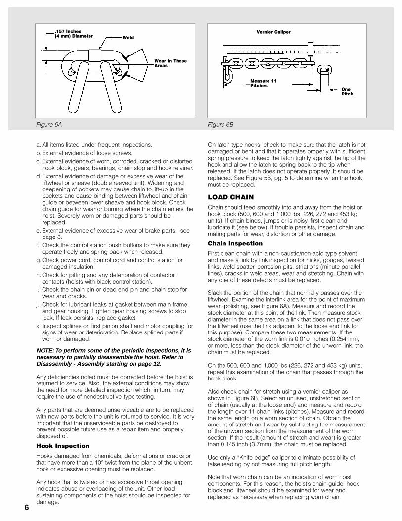
Slack the portion of the chain that normally passes over theliftwheel. Examine the interlink area for the point of maximumwear (polishing, see Figure 6A). Measure and record thestock diameter at this point of the link. Then measure stockdiameter in the same area on a link that does not pass overthe liftwheel (use the link adjacent to the loose end link forthis purpose). Compare these two measurements. If thestock diameter of the worn link is 0.010 inches (0.254mm),or more, less than the stock diameter of the unworn link, thechain must be replaced.
On the 500, 600 and 1,000 lbs (226, 272 and 453 kg) units,repeat this examination of the chain that passes through thehook block.
Also check chain for stretch using a vernier caliper asshown in Figure 6B. Select an unused, unstretched sectionof chain (usually at the loose end) and measure and recordthe length over 11 chain links (pitches). Measure and recordthe same length on a worn section of chain. Obtain theamount of stretch and wear by subtracting the measurementof the unworn section from the measurement of the wornsection. If the result (amount of stretch and wear) is greaterthan 0.145 inch (3.7mm), the chain must be replaced.
Use only a “Knife-edge” caliper to eliminate possibility offalse reading by not measuring full pitch length.
Note that worn chain can be an indication of worn hoistcomponents. For this reason, the hoist’s chain guide, hookblock and liftwheel should be examined for wear andreplaced as necessary when replacing worn chain.
Weld.157 Inches(4 mm) Diameter
Wear in TheseAreas
Vernier Caliper
Measure 11Pitches
OnePitch
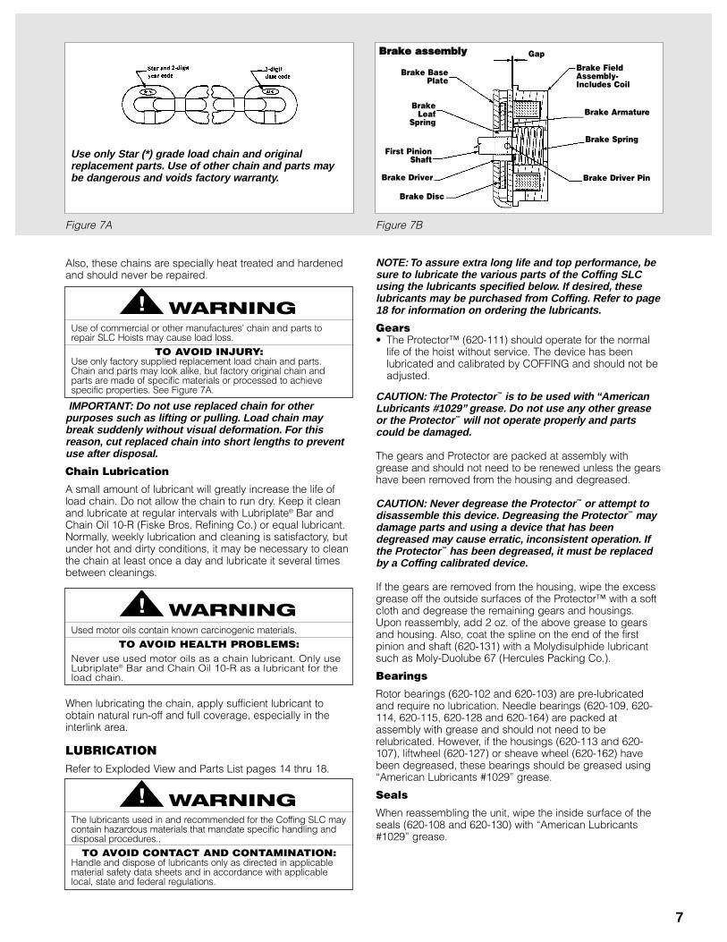
Figure 7A Figure 7B
7
Also, these chains are specially heat treated and hardenedand should never be repaired.
IMPORTANT: Do not use replaced chain for otherpurposes such as lifting or pulling. Load chain maybreak suddenly without visual deformation. For thisreason, cut replaced chain into short lengths to preventuse after disposal.
Chain Lubrication
A small amount of lubricant will greatly increase the life ofload chain. Do not allow the chain to run dry. Keep it cleanand lubricate at regular intervals with Lubriplate® Bar andChain Oil 10-R (Fiske Bros. Refining Co.) or equal lubricant.Normally, weekly lubrication and cleaning is satisfactory, butunder hot and dirty conditions, it may be necessary to cleanthe chain at least once a day and lubricate it several timesbetween cleanings.
When lubricating the chain, apply sufficient lubricant toobtain natural run-off and full coverage, especially in theinterlink area.
LUBRICATIONRefer to Exploded View and Parts List pages 14 thru 18.
Use only Star (*) grade load chain and originalreplacement parts. Use of other chain and parts maybe dangerous and voids factory warranty.
Use of commercial or other manufactures’ chain and parts torepair SLC Hoists may cause load loss.
TO AVOID INJURY:Use only factory supplied replacement load chain and parts.Chain and parts may look alike, but factory original chain andparts are made of specific materials or processed to achievespecific properties. See Figure 7A.
Used motor oils contain known carcinogenic materials.
TO AVOID HEALTH PROBLEMS:Never use used motor oils as a chain lubricant. Only useLubriplate® Bar and Chain Oil 10-R as a lubricant for theload chain.
NOTE: To assure extra long life and top performance, besure to lubricate the various parts of the Coffing SLCusing the lubricants specified below. If desired, theselubricants may be purchased from Coffing. Refer to page18 for information on ordering the lubricants.
Gears• The Protector™ (620-111) should operate for the normal
life of the hoist without service. The device has beenlubricated and calibrated by COFFING and should not beadjusted.
CAUTION: The Protector™ is to be used with “AmericanLubricants #1029” grease. Do not use any other greaseor the Protector™ will not operate properly and partscould be damaged.
The gears and Protector are packed at assembly withgrease and should not need to be renewed unless the gearshave been removed from the housing and degreased.
CAUTION: Never degrease the Protector™ or attempt todisassemble this device. Degreasing the Protector™ maydamage parts and using a device that has beendegreased may cause erratic, inconsistent operation. Ifthe Protector™ has been degreased, it must be replacedby a Coffing calibrated device.
If the gears are removed from the housing, wipe the excessgrease off the outside surfaces of the Protector™ with a softcloth and degrease the remaining gears and housings.Upon reassembly, add 2 oz. of the above grease to gearsand housing. Also, coat the spline on the end of the firstpinion and shaft (620-131) with a Molydisulphide lubricantsuch as Moly-Duolube 67 (Hercules Packing Co.).
Bearings
Rotor bearings (620-102 and 620-103) are pre-lubricatedand require no lubrication. Needle bearings (620-109, 620-114, 620-115, 620-128 and 620-164) are packed atassembly with grease and should not need to berelubricated. However, if the housings (620-113 and 620-107), liftwheel (620-127) or sheave wheel (620-162) havebeen degreased, these bearings should be greased using“American Lubricants #1029” grease.
Seals
When reassembling the unit, wipe the inside surface of theseals (620-108 and 620-130) with “American Lubricants#1029” grease.
The lubricants used in and recommended for the Coffing SLC maycontain hazardous materials that mandate specific handling anddisposal procedures..
TO AVOID CONTACT AND CONTAMINATION:Handle and dispose of lubricants only as directed in applicablematerial safety data sheets and in accordance with applicablelocal, state and federal regulations.
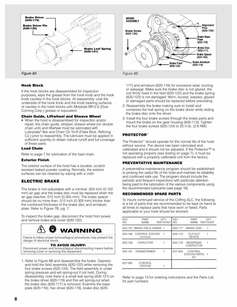
Brake BasePlate
Brake FieldAssembly-Includes Coil
Brake Armature
Brake Spring
Gap
Brake Driver Pin
Brake Leaf
Spring
First PinionShaft
Brake Driver
Brake Disc
BBrraakkee aasssseemmbbllyy
8
Hook Block
If the hook blocks are disassembled for inspectionpurposes, wipe the grease from the hook knob and the hookknob cavities in the hook blocks. At reassembly, coat theunderside of the hook knob and the knob bearing surfacesof cavities in the hook blocks with Molykote BR-2-S (DowCorning Corp.) grease or equivalent.
Chain Guide, Liftwheel and Sheave Wheel• When the hoist is disassembled for inspection and/or
repair, the chain guide, stripper, sheave wheel (on doublechain unit) and liftwheel must be lubricated withLubriplate® Bar and Chain Oil 10-R (Fiske Bros. RefiningCo.) prior to reassembly. The lubricant must be applied insufficient quantity to obtain natural runoff and full coverageof these parts.
Load Chain
Refer to page 7 for lubrication of the load chain.
Exterior Finish
The exterior surface of the hoist has a durable, scratchresistant baked powder coating. Normally, the exteriorsurfaces can be cleaned by wiping with a cloth.
ELECTRIC BRAKE
The brake is non-adjustable with a nominal .004 inch (0.102mm) air gap and the brake disc must be replaced when theair gap reaches .012 inch (0.305 mm). The brake spacershould be no more than .012 inch (0.305 mm) thicker thanthe combined thickness of the brake disc and armatureplate. Refer to Figure 7B, pg. 7.
To inspect the brake gap, disconnect the hoist from powerand remove brake end cover (620-132).
1. Refer to Figure 8B and disassemble the brake. Depressand hold the field assembly (620-122) while removing thefour brake screws (620-124). The field assembly is underspring pressure and will spring-out if not held. Duringdisassembly, note there is a small leaf spring (620-121) onthe brake driver (620-119) and this will spring-out whenthe brake disc (620-117) is removed. Examine the baseplate (620-116), hex driver (620-119), brake disc (620-
117) and armature (620-118) for excessive wear, scoringor warpage. Make sure the brake disc is not glazed, thecoil firmly fixed in the field (620-122) and the brake spring(620-123) is not damaged. Worn, scored, warped, glazedor damaged parts should be replaced before preceding.
2. Reassemble the brake making sure to install andcompress the leaf spring on the brake driver while slidingthe brake disc onto the driver.
3. Install the four brake screws through the brake parts andmount the brake on the gear housing (620-113). Tightenthe four brake screws (620-124) to 25 in.lb. (2.8 NM).
PROTECTOR™
The Protector™ should operate for the normal life of the hoistwithout service. The device has been lubricated andcalibrated and it should not be adjusted. If the Protector™ isnot operating properly (see testing on page 7), it must bereplaced with a properly calibrated unit from the factory.
PREVENTATIVE MAINTENANCE
A preventative maintenance program should be establishedto prolong the useful life of the hoist and maintain its reliabilityand continued safe use. The program should include theperiodic and frequent inspections with particular attentionbeing paid to the lubrication of the various components usingthe recommended lubricants (see page 18).
RECOMMENDED SPARE PARTS
To insure continued service of the Coffing SLC, the followingis a list of parts that are recommended to be kept on hand atall times to replace parts that have worn or failed. Partsapplicable to your hoist should be stocked.
KEY. PART QTY. KEY PART QTYNO. NAME PER HOIST NO. NAME PER HOIST
620-122 BRAKE FIELD ASSEM. 1 620-117 BRAKE DISC 1
620-186 CONTROL STATION 1 620-110 CUT-OUT 1(ORANGE) DEVICE
620-106 CAPACITOR 1 620-178 REVERSING 1CONTACTOR
620-181 TRANSFORMER 1 627-563 CONTROL STATION PARTS 1
KIT
627-565 CONTROL STATION 1
Refer to page 13 for ordering instructions and the Parts Listfor part numbers.
Failure to follow proper lockout/tagout procedures may present thedanger of electrical shock.
TO AVOID INJURY:Disconnect power and lockout/tagout disconnecting means beforeremoving cover or servicing this equipment.
Figure 8A
Brake Leaf Spring(620-121)
Brake Driver(620-119)
Figure 8A Figure 8B
Brake Driver Pin(620-120)
9
A. No voltage at hoist.
B. Open control circuit due to loose connections or broken wires in circuit; motorthermal protector open; control station contacts not closing; open or shortedwinding in transformer; transformer thermal cut-out open; mechanical binding incontactor; open or shorted winding in contactor coil.
C. Wrong voltage or frequency.
D. Low voltage.
E. Brake not releasing due to open or shorted coil, defective diodes or brake discbinding.
F. Excessive load.
G. Phase failure (single phasing-three phase units only) - open circuit, grounded orfaulty connection in one line of power supply system, hoist wiring, contactor, motorleads or windings.
A. Check for blown fuse or tripped circuit breaker or open disconnect switch in mainline or branch circuit. Replace fuse, reset circuit breaker or close switch.
B. Check electrical continuity through motor thermal protector. If it is open, allowmotor to cool. If this does not correct the trouble, use wiring diagram to checkelectrical continuity of wiring, transformer, contactor and control station contacts.Repair wiring or replace defective part.
C. Make sure that the power supply to hoist is the same as that shown on theidentification plate on bottom of hoist.
D. Check power supply system to make sure it complies with the requirements listedunder “power supply system” starting on page 2.
E. Check coil continuity, diodes (see page 10) and connections. Make sure brakedisc slides freely on brake driver and brake spring is not broken. Replace coil(brake field), repair connections, remove burrs from brake driver so that brake discslides freely and/or replace brake spring.
F. Reduce load to capacity limit as indicated on identification and capacity labels onhoist.
G. Check for electrical continuity and repair or replace defective part.
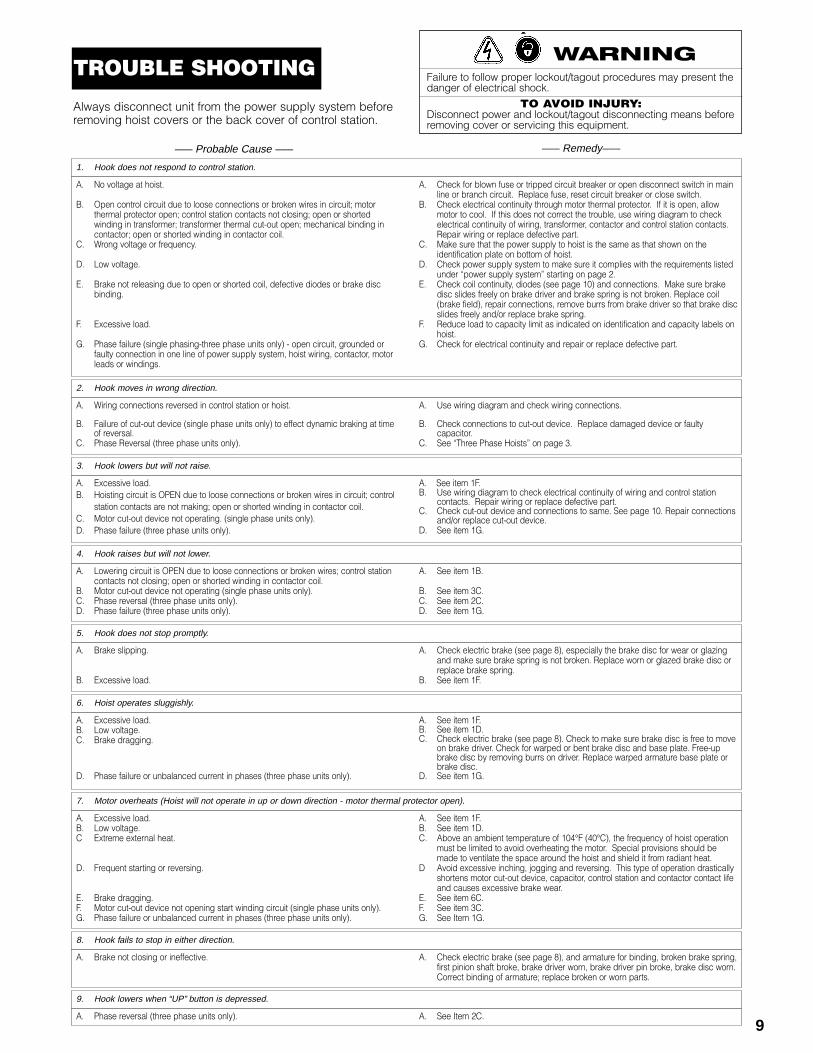
1. Hook does not respond to control station.
A. Wiring connections reversed in control station or hoist.
B. Failure of cut-out device (single phase units only) to effect dynamic braking at timeof reversal.
C. Phase Reversal (three phase units only).
A. Use wiring diagram and check wiring connections.
B. Check connections to cut-out device. Replace damaged device or faultycapacitor.
C. See “Three Phase Hoists” on page 3.
2. Hook moves in wrong direction.
A. Excessive load.B. Hoisting circuit is OPEN due to loose connections or broken wires in circuit; control
station contacts are not making; open or shorted winding in contactor coil.C. Motor cut-out device not operating. (single phase units only).D. Phase failure (three phase units only).
A. See item 1F.B. Use wiring diagram to check electrical continuity of wiring and control station
contacts. Repair wiring or replace defective part.C. Check cut-out device and connections to same. See page 10. Repair connections
and/or replace cut-out device.D. See item 1G.
3. Hook lowers but will not raise.
A. Lowering circuit is OPEN due to loose connections or broken wires; control stationcontacts not closing; open or shorted winding in contactor coil.
B. Motor cut-out device not operating (single phase units only).C. Phase reversal (three phase units only).D. Phase failure (three phase units only).
A. See item 1B.
B. See item 3C.C. See item 2C.D. See item 1G.
4. Hook raises but will not lower.
A. Brake slipping.
B. Excessive load.
A. Check electric brake (see page 8), especially the brake disc for wear or glazingand make sure brake spring is not broken. Replace worn or glazed brake disc orreplace brake spring.
B. See item 1F.
5. Hook does not stop promptly.
A. Excessive load.B. Low voltage.C. Brake dragging.
D. Phase failure or unbalanced current in phases (three phase units only).
A. See item 1F.B. See item 1D.C. Check electric brake (see page 8). Check to make sure brake disc is free to move
on brake driver. Check for warped or bent brake disc and base plate. Free-upbrake disc by removing burrs on driver. Replace warped armature base plate orbrake disc.
D. See item 1G.
6. Hoist operates sluggishly.
A. Excessive load.B. Low voltage.C Extreme external heat.
D. Frequent starting or reversing.
E. Brake dragging.F. Motor cut-out device not opening start winding circuit (single phase units only).G. Phase failure or unbalanced current in phases (three phase units only).
A. See item 1F.B. See item 1D.C. Above an ambient temperature of 104°F (40°C), the frequency of hoist operation
must be limited to avoid overheating the motor. Special provisions should bemade to ventilate the space around the hoist and shield it from radiant heat.
D Avoid excessive inching, jogging and reversing. This type of operation drasticallyshortens motor cut-out device, capacitor, control station and contactor contact lifeand causes excessive brake wear.
E. See item 6C.F. See item 3C.G. See Item 1G.
7. Motor overheats (Hoist will not operate in up or down direction - motor thermal protector open).
A. Brake not closing or ineffective. A. Check electric brake (see page 8), and armature for binding, broken brake spring,first pinion shaft broke, brake driver worn, brake driver pin broke, brake disc worn.Correct binding of armature; replace broken or worn parts.
8. Hook fails to stop in either direction.
A. Phase reversal (three phase units only). A. See Item 2C.
9. Hook lowers when “UP” button is depressed.
Always disconnect unit from the power supply system beforeremoving hoist covers or the back cover of control station.
Failure to follow proper lockout/tagout procedures may present thedanger of electrical shock.
TO AVOID INJURY:Disconnect power and lockout/tagout disconnecting means beforeremoving cover or servicing this equipment.
––– Probable Cause ––– ––– Remedy–––
TROUBLE SHOOTING
CoilsVoltage Current Nominal D.C.
Draw (Amps) Resistance (Ohms)Contactor 115 0.02 765Coils 48 0.2 98.4Brake *115 - *272Field **220 - 1120
***280 - 1608Cut-out 115 0.1 Terminals 3 to 4: 0.3Device 220 N.A. Terminals 3 to 4: 0.8
*To measure 115 volt brake coil resistance, carefully cut andpeel back the shrink tubing on the brake coil leads toexpose the diodes. Trace the leads from the coil to thediodes. Connect the ohmmeter leads at the coil side of thediodes (refer to the wiring diagram) and measure theresistance. If coil is ok, reinsulate the brake coil leads anddiodes using electrical tape. Diodes are checked byconnecting the ohmmeter to the ends of the brake coilleads, checking for an open or short circuit, reversing theconnections to the ohmmeter and again checking for anopen or short circuit. If there is an indication of an open orshort circuit with the original and reversed connections,diodes are defective and the brake field (620-122), whichincludes the diodes, must be replaced. Usable diodes areindicated by continuity with the original connections and anopen circuit when the connections are reversed or, an opencircuit with the original connection and continuity withreversed connections.
**220 volt brake coil is used on 220-3-50/60 and, 380-3-50,415-3-50 and 460-3-60 hoists.
***280 volt brake is used on 575-3-60 hoists.
10
Open or Short Circuit in Electrical Components
Open circuits in electrical components may be detected byisolating the component and checking for continuity usingan ohmmeter. Short circuits are indicated by D.C. resistancesubstantially below the nominal D.C. resistance. Motorcurrent draw should be measured at the end of the powercord while the hoist is raising rated load. Check cut-outdevice (on single phase units only) by measuring coilresistance (terminals 3 and 4) and making sure the contact(terminals 2 and 4) is open.
Electrical Data for Components
S t a t o r sVolts-Phase-Hertz Full Load Current Nominal D.C.
(Amps) Resistance(Ohms)
110 to 120-1-50/60 2.7 Yellow to Red: 7.7Blue to Black: 6.2
220-3-50 1.1 White to Red: 26.8230-3-60 0.6 White to Black: 26.8
Red to Black: 26.8380-3-50 0.63 White to Red: 72.6415-3-50 0.58 White to Black: 72.6460-3-60 0.88 Red to Black: 72.6575-3-60 0.4 White to Red:140.0
White to Black:140.0Red to Black:140.0
TransformersPrimary 220/380v. 230/460v. 460v. 575v. 575v.Secondary 48v. 115v. 48v. 115v. 48v.Leads Nominal D.C. Resistance (ohms)Black to Purple 11.7 71.0 11.9 73 98White to Red 228.0 224.0 White to Yellow 614.0 902.0 - - -Red to Yellow 384.0 682.0 - - -White to Orange - - 916.0 1100 1100
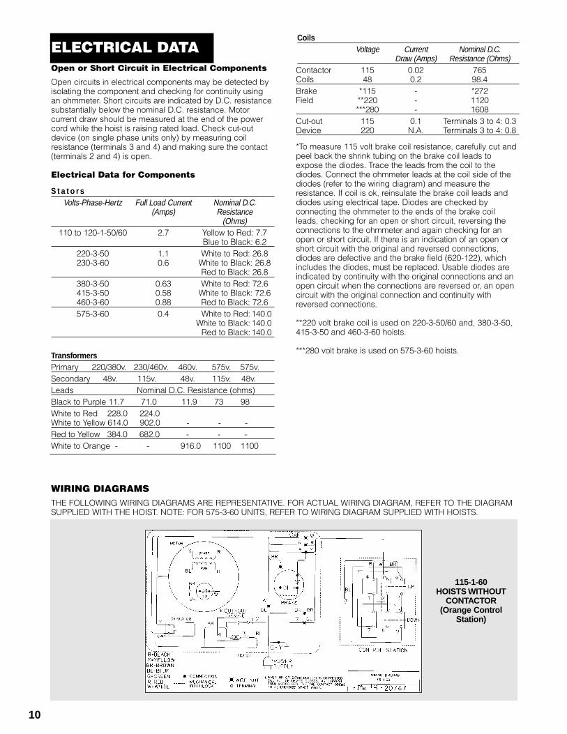
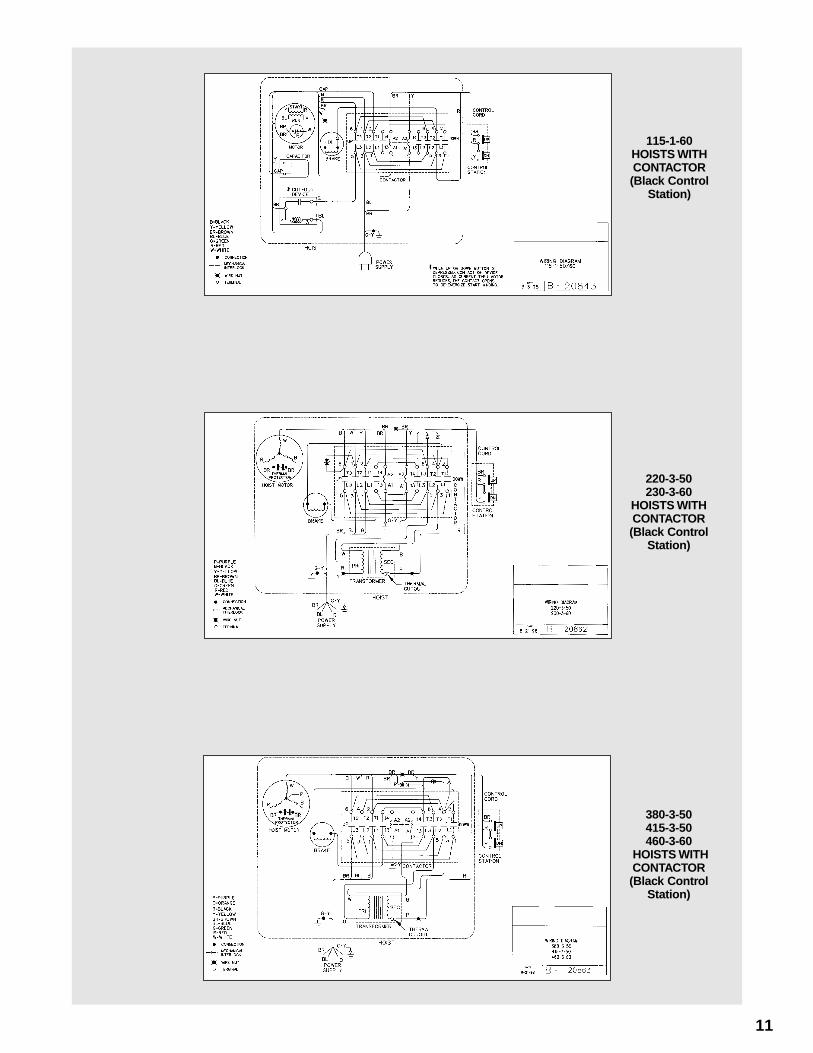
WIRING DIAGRAMSTHE FOLLOWING WIRING DIAGRAMS ARE REPRESENTATIVE. FOR ACTUAL WIRING DIAGRAM, REFER TO THE DIAGRAMSUPPLIED WITH THE HOIST. NOTE: FOR 575-3-60 UNITS, REFER TO WIRING DIAGRAM SUPPLIED WITH HOISTS.
115-1-60 HOISTS WITHOUT
CONTACTOR(Orange Control
Station)
ELECTRICAL DATA
11
115-1-60 HOISTS WITHCONTACTOR (Black Control
Station)
220-3-50230-3-60
HOISTS WITHCONTACTOR (Black Control
Station)
380-3-50415-3-50460-3-60
HOISTS WITHCONTACTOR (Black Control
Station)
12
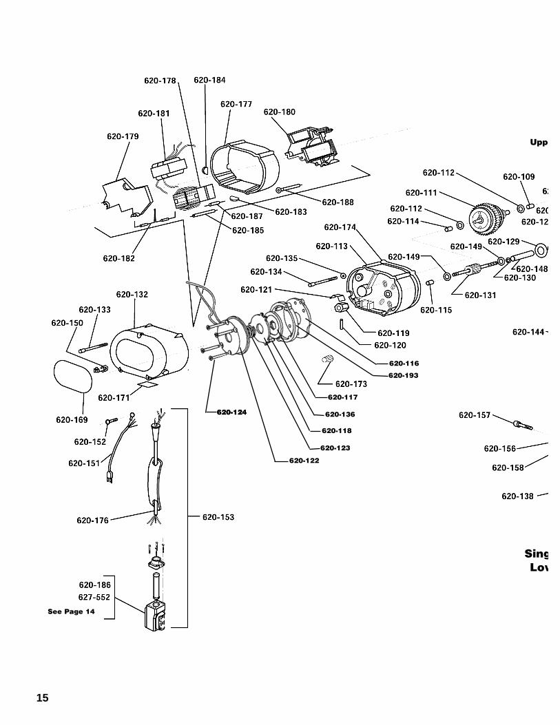
When disassembling and assembling the Coffing SLC, referto the exploded view and the parts list on pages 14 thru 18.These show the proper relationship of the parts, the namesof the parts and the required quantities of the parts. Inaddition, please observe the following:
1. Needle bearings are pressed into the gear housing(620-113), main frame (620-107), liftwheel (620-127)and lower sheave wheel (620-162). Unless they are tobe replaced, do not attempt to remove these bearings.
2. A liftwheel seal (620-108) is pressed into the main frame(620-107) and a seal (620-130) is pressed into the endof the liftwheel shaft (620-148). Be careful that theseseals are not cut or damaged during disassembly andreassembly.
3. Refer to page 8 for disassembly, inspection andreassembly of the brake.
4. When removing the brake driver (620-119), it must besupported while driving out the retainer pin (620-120).At reassembly, it must also be supported and theretainer pin must be driven in so that it is below thesurface of the driver. File away any burrs and use thebrake disc (620-117) as a gauge to make sure it willslide freely on the driver.
5. Do not attempt to disassemble the Protector™ - refer topage 8.
6. Refer to page 7 for lubrication instructions.7. See next section for load chain removal and installation.8. Tighten the various screws as follows:
KEY-NO. PART NAME SEATING TORQUELB. IN. NM
620-126 Pin Retainer Plate Screw 25 2.8620-154 Motor Cover Screw 25 2.8620-134 Gear Housing Screw 25 2.8620-133 Brake End Cover Screw 25 2.8620-168 Dead End Plate Screw 125 14.1620-140 Hook Retainer Screw 10 1.1620-157 Hook Block Screw
500 and 600 lbs (226 and 272 kg) units 50 5.6250 and 300 lbs (113 and 136 kg) units 125 14.1
620-152 Power Cord Ground Screw 20 2.2
9. When removing the stator (620-100), first remove thebrake end cover (620-132). Disconnect stator leadsfrom the wiring or contactor. At the other end, removethe motor end cover (620-105). On single phase units,use an insulated screw driver to short between the bareterminals of the capacitor to discharge it. A spark maybe produced. Disconnect wiring to the capacitor and
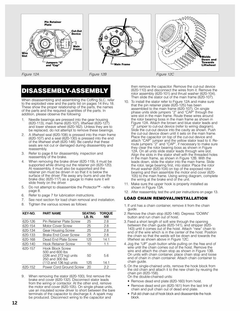
then remove the capacitor. Remove the cut-out device(620-110) and disconnect the wires from it. Remove therotor assembly (620-101) and thrust washer (620-104).Then slide the stator out of the main frame (620-107).
10. To install the stator refer to Figure 12A and make surethat the pin retainer plate (620-125) has beenassembled to the main frame (620-107). On singlephase units slide jumpers “2” and “CAP” through thewire slot in the main frame. Route these wires aroundthe rotor bearing boss in the main frame as shown inFigure 12A. Attach the brown and blue stator leads and“2” jumper to cut-out device (refer to wiring diagram).Slide the cut-out device into the cavity as shown. Pushthe cut-out device down until it sets on the main frame.Place the capacitor on top of the cut-out device andattach “CAP” jumper and the yellow stator lead to it. Re-route jumpers “2” and “CAP”, if necessary to make surethey clear the rotor bearing boss as shown in Figure12A. On all units slide stator leads through wire slot.Align the slots in the stator shell with the threaded holesin the main frame, as shown in Figure 12B. With theleads down, slide the stator into the main frame. Slidethe rotor, large bearing first, into stator. Place the rotorthrust washer (620-104) on top of the exposed rotorbearing and then assemble the motor end cover (620-105) to the main frame. Using wiring diagram, completethe wiring at the brake end of the unit.
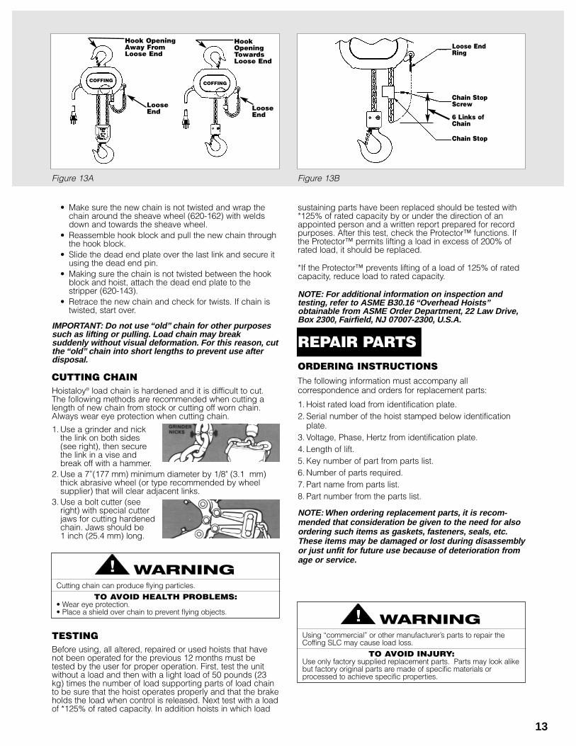
11. Make sure the upper hook is properly installed asshown in Figure 13A.
12. After reassembly, test the unit per instructions on page 13.
LOAD CHAIN REMOVAL/INSTALLATION
1. If unit has a chain container, remove it from the chainguide.
2. Remove the chain stop (620-146). Depress “DOWN”button and run chain out of hoist.
3. Feed a short length of soft wire through the openingbetween the chain guide (620-141), and stripper (620-143) until it comes out of the hoist. Attach “new” chain toend of the wire which is in the center of the hoist. Positionthe chain so that the welds will be down and towards theliftwheel as shown above in Figure 12C.
4. Jog the “UP” push button while pulling on the free end ofwire until the chain comes out of the hoist. Remove thewire and attach the chain stop as shown in Figure 13B.On units with chain container, place chain stop and looseend of chain in chain container. Attach chain container tochain guide.
5. On the single-chained units, remove the hook block fromthe old chain and attach it to the new chain by reusing thechain pin (620-158).On the double-chained units:• Remove dead end plate (620-160) from hoist.• Remove dead end pin (620-161) from the last link of
chain and pull chain out of dead end plate.• Pull old chain out of hook block and disassemble the hook
block.
Figure 12A Figure 12B Figure 12C
WireSlot
Pin RetainerPlate
Cut-OutDevice
MainFrame
Jumpers “2”and “Cap” Main Frame
DISASSEMBLY-ASSEMBLY
WeldsDown andTowardsLiftwheel
13
• Make sure the new chain is not twisted and wrap thechain around the sheave wheel (620-162) with weldsdown and towards the sheave wheel.
• Reassemble hook block and pull the new chain throughthe hook block.
• Slide the dead end plate over the last link and secure itusing the dead end pin.
• Making sure the chain is not twisted between the hookblock and hoist, attach the dead end plate to thestripper (620-143).
• Retrace the new chain and check for twists. If chain istwisted, start over.
IMPORTANT: Do not use “old” chain for other purposessuch as lifting or pulling. Load chain may breaksuddenly without visual deformation. For this reason, cutthe “old” chain into short lengths to prevent use afterdisposal.
CUTTING CHAINHoistaloy® load chain is hardened and it is difficult to cut.The following methods are recommended when cutting alength of new chain from stock or cutting off worn chain.Always wear eye protection when cutting chain.
1. Use a grinder and nickthe link on both sides(see right), then securethe link in a vise andbreak off with a hammer.
2. Use a 7”(177 mm) minimum diameter by 1/8" (3.1 mm)thick abrasive wheel (or type recommended by wheelsupplier) that will clear adjacent links.
3. Use a bolt cutter (seeright) with special cutterjaws for cutting hardenedchain. Jaws should be 1 inch (25.4 mm) long.
TESTINGBefore using, all altered, repaired or used hoists that havenot been operated for the previous 12 months must betested by the user for proper operation. First, test the unitwithout a load and then with a light load of 50 pounds (23kg) times the number of load supporting parts of load chainto be sure that the hoist operates properly and that the brakeholds the load when control is released. Next test with a loadof *125% of rated capacity. In addition hoists in which load
sustaining parts have been replaced should be tested with*125% of rated capacity by or under the direction of anappointed person and a written report prepared for recordpurposes. After this test, check the Protector™ functions. Ifthe Protector™ permits lifting a load in excess of 200% ofrated load, it should be replaced.
*If the Protector™ prevents lifting of a load of 125% of ratedcapacity, reduce load to rated capacity.
NOTE: For additional information on inspection andtesting, refer to ASME B30.16 “Overhead Hoists”obtainable from ASME Order Department, 22 Law Drive,Box 2300, Fairfield, NJ 07007-2300, U.S.A.
ORDERING INSTRUCTIONSThe following information must accompany allcorrespondence and orders for replacement parts:
1. Hoist rated load from identification plate.2. Serial number of the hoist stamped below identification
plate.3. Voltage, Phase, Hertz from identification plate.4. Length of lift.5. Key number of part from parts list.6. Number of parts required.7. Part name from parts list.8. Part number from the parts list.
NOTE: When ordering replacement parts, it is recom-mended that consideration be given to the need for alsoordering such items as gaskets, fasteners, seals, etc.These items may be damaged or lost during disassemblyor just unfit for future use because of deterioration fromage or service.
Cutting chain can produce flying particles.
TO AVOID HEALTH PROBLEMS:• Wear eye protection.• Place a shield over chain to prevent flying objects.
Using “commercial” or other manufacturer’s parts to repair theCoffing SLC may cause load loss.
TO AVOID INJURY:Use only factory supplied replacement parts. Parts may look alikebut factory original parts are made of specific materials orprocessed to achieve specific properties.
Figure 13A Figure 13B
Loose EndRing
Chain StopScrew
6 Links ofChain
Chain Stop
Hook OpeningAway FromLoose End
LooseEnd
HookOpeningTowardsLoose End
LooseEnd
COFFING COFFING
REPAIR PARTS
14
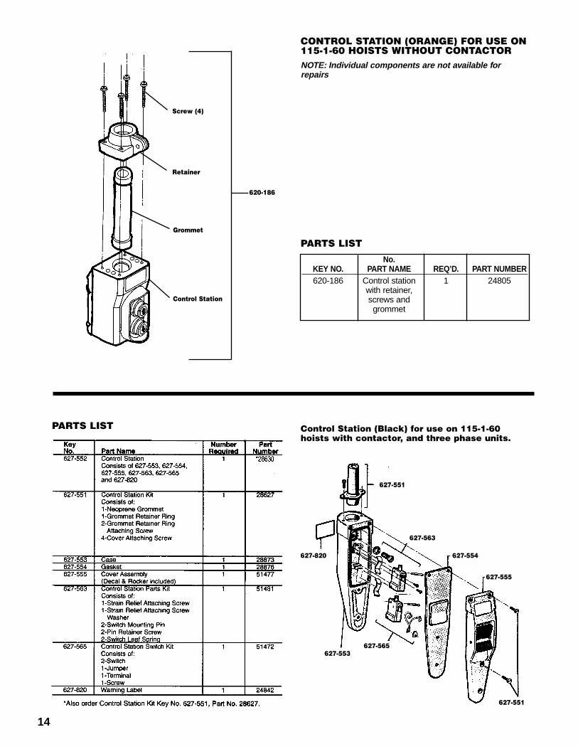
620-186
Grommet
Control Station
Retainer
Screw (4)
627-551
627-563
627-554
627-555
627-551
627-565627-553
627-820
No.KEY NO. PART NAME REQ’D. PART NUMBER620-186 Control station 1 24805
with retainer,screws andgrommet
CONTROL STATION (ORANGE) FOR USE ON115-1-60 HOISTS WITHOUT CONTACTORNOTE: Individual components are not available forrepairs
Control Station (Black) for use on 115-1-60hoists with contactor, and three phase units.
PARTS LIST
PARTS LIST

19
NOTES
15
620-123
620-124
620-122
620-118
620-136
620-117
620-193
620-116
See Page 14
620-124
(Uppe
SingLow
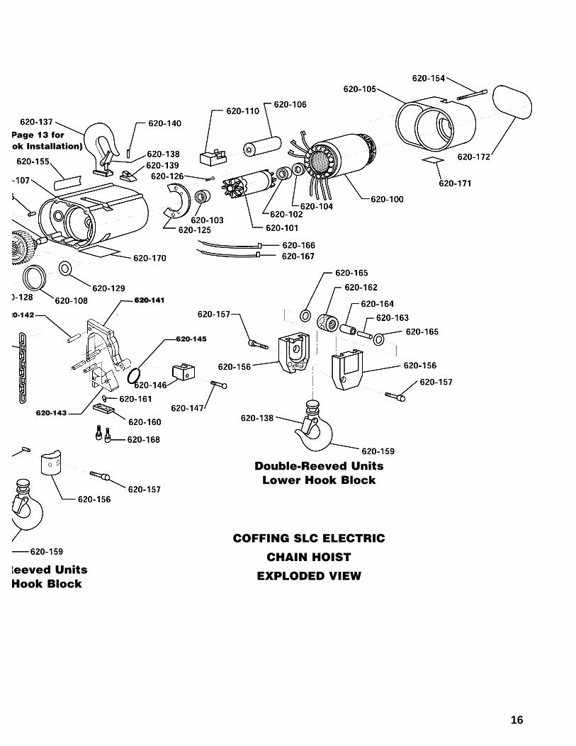
16
COFFING SLC ELECTRIC
CHAIN HOIST
EXPLODED VIEW
20-142
620-145
620-141620-141
620-143
Page 13 for ok Installation)
Reeved UnitsHook Block
Double-Reeved UnitsLower Hook Block
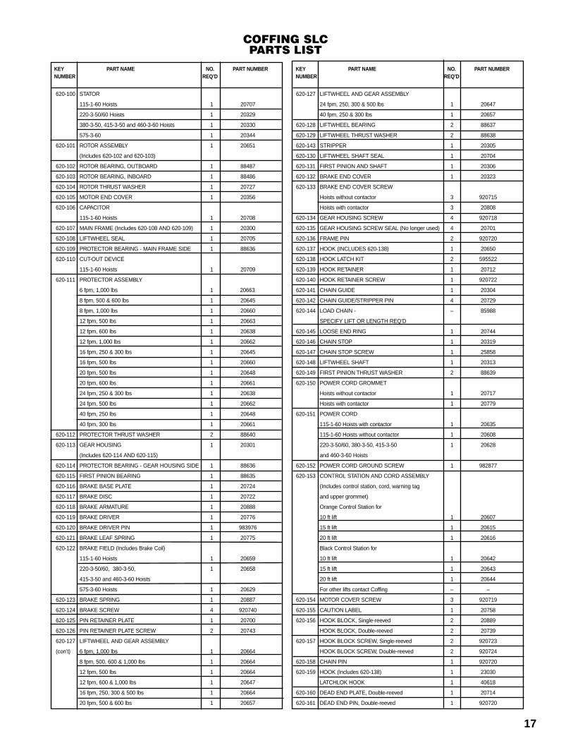
620-100 STATOR
115-1-60 Hoists 1 20707
220-3-50/60 Hoists 1 20329
380-3-50, 415-3-50 and 460-3-60 Hoists 1 20330
575-3-60 1 20344
620-101 ROTOR ASSEMBLY 1 20651
(Includes 620-102 and 620-103)
620-102 ROTOR BEARING, OUTBOARD 1 88487
620-103 ROTOR BEARING, INBOARD 1 88486
620-104 ROTOR THRUST WASHER 1 20727
620-105 MOTOR END COVER 1 20356
620-106 CAPACITOR
115-1-60 Hoists 1 20708
620-107 MAIN FRAME (Includes 620-108 AND 620-109) 1 20300
620-108 LIFTWHEEL SEAL 1 20705
620-109 PROTECTOR BEARING - MAIN FRAME SIDE 1 88636
620-110 CUT-OUT DEVICE
115-1-60 Hoists 1 20709
620-111 PROTECTOR ASSEMBLY
6 fpm, 1,000 lbs 1 20663
8 fpm, 500 & 600 lbs 1 20645
8 fpm, 1,000 lbs 1 20660
12 fpm, 500 lbs 1 20663
12 fpm, 600 lbs 1 20638
12 fpm, 1,000 lbs 1 20662
16 fpm, 250 & 300 lbs 1 20645
16 fpm, 500 lbs 1 20660
20 fpm, 500 lbs 1 20648
20 fpm, 600 lbs 1 20661
24 fpm, 250 & 300 lbs 1 20638
24 fpm, 500 lbs 1 20662
40 fpm, 250 lbs 1 20648
40 fpm, 300 lbs 1 20661
620-112 PROTECTOR THRUST WASHER 2 88640
620-113 GEAR HOUSING 1 20301
(Includes 620-114 AND 620-115)
620-114 PROTECTOR BEARING - GEAR HOUSING SIDE 1 88636
620-115 FIRST PINION BEARING 1 88635
620-116 BRAKE BASE PLATE 1 20724
620-117 BRAKE DISC 1 20722
620-118 BRAKE ARMATURE 1 20888
620-119 BRAKE DRIVER 1 20776
620-120 BRAKE DRIVER PIN 1 983976
620-121 BRAKE LEAF SPRING 1 20775
620-122 BRAKE FIELD (Includes Brake Coil)
115-1-60 Hoists 1 20659
220-3-50/60, 380-3-50, 1 20658
415-3-50 and 460-3-60 Hoists
575-3-60 Hoists 1 20629
620-123 BRAKE SPRING 1 20887
620-124 BRAKE SCREW 4 920740
620-125 PIN RETAINER PLATE 1 20700
620-126 PIN RETAINER PLATE SCREW 2 20743
620-127 LIFTWHEEL AND GEAR ASSEMBLY
(con’t) 6 fpm, 1,000 lbs 1 20664
8 fpm, 500, 600 & 1,000 lbs 1 20664
12 fpm, 500 lbs 1 20664
12 fpm, 600 & 1,000 lbs 1 20647
16 fpm, 250, 300 & 500 lbs 1 20664
20 fpm, 500 & 600 lbs 1 20657
17
620-127 LIFTWHEEL AND GEAR ASSEMBLY
24 fpm, 250, 300 & 500 lbs 1 20647
40 fpm, 250 & 300 lbs 1 20657
620-128 LIFTWHEEL BEARING 2 88637
620-129 LIFTWHEEL THRUST WASHER 2 88638
620-143 STRIPPER 1 20305
620-130 LIFTWHEEL SHAFT SEAL 1 20704
620-131 FIRST PINION AND SHAFT 1 20306
620-132 BRAKE END COVER 1 20323
620-133 BRAKE END COVER SCREW
Hoists without contactor 3 920715
Hoists with contactor 3 20808
620-134 GEAR HOUSING SCREW 4 920718
620-135 GEAR HOUSING SCREW SEAL (No longer used) 4 20701
620-136 FRAME PIN 2 920720
620-137 HOOK (INCLUDES 620-138) 1 20650
620-138 HOOK LATCH KIT 2 595522
620-139 HOOK RETAINER 1 20712
620-140 HOOK RETAINER SCREW 1 920722
620-141 CHAIN GUIDE 1 20304
620-142 CHAIN GUIDE/STRIPPER PIN 4 20729
620-144 LOAD CHAIN - – 85988
SPECIFY LIFT OR LENGTH REQ’D
620-145 LOOSE END RING 1 20744
620-146 CHAIN STOP 1 20319
620-147 CHAIN STOP SCREW 1 25858
620-148 LIFTWHEEL SHAFT 1 20313
620-149 FIRST PINION THRUST WASHER 2 88639
620-150 POWER CORD GROMMET
Hoists without contactor 1 20717
Hoists with contactor 1 20779
620-151 POWER CORD
115-1-60 Hoists with contactor 1 20635
115-1-60 Hoists without contactor 1 20608
220-3-50/60, 380-3-50, 415-3-50 1 20628
and 460-3-60 Hoists
620-152 POWER CORD GROUND SCREW 1 982877
620-153 CONTROL STATION AND CORD ASSEMBLY
(Includes control station, cord, warning tag
and upper grommet)
Orange Control Station for
10 ft lift 1 20607
15 ft lift 1 20615
20 ft lift 1 20616
Black Control Station for
10 ft lift 1 20642
15 ft lift 1 20643
20 ft lift 1 20644
For other lifts contact Coffing – –
620-154 MOTOR COVER SCREW 3 920719
620-155 CAUTION LABEL 1 20758
620-156 HOOK BLOCK, Single-reeved 2 20889
HOOK BLOCK, Double-reeved 2 20739
620-157 HOOK BLOCK SCREW, Single-reeved 2 920723
HOOK BLOCK SCREW, Double-reeved 2 920724
620-158 CHAIN PIN 1 920720
620-159 HOOK (Includes 620-138) 1 23030
LATCHLOK HOOK 1 40618
620-160 DEAD END PLATE, Double-reeved 1 20714
620-161 DEAD END PIN, Double-reeved 1 920720
KEY PART NAME NO. PART NUMBERNUMBER REQ’D
KEY PART NAME NO. PART NUMBERNUMBER REQ’D
COFFING SLC PARTS LIST
KEY PART NAME NO. PART NUMBERNUMBER REQ’D
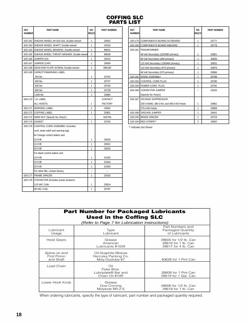
620-179 COMPONENTS BOARD-OUTBOARD 1 20777
620-180 COMPONENTS BOARD-INBOARD 1 20778
620-181 TRANSFORMER
48 Volt Secondary (220/380 primary) 1 20851
48 Volt Secondary (460 primary) 1 20834
115 Volt Secondary (230/460 primary) 1 20831
115 Volt Secondary (575 primary) 1 20876
48 Volt Secondary (575 primary) 1 20866
620-182 DIODE ASSEMBLY 1 20789
620-183 CONTROL CORD PLUG 1 20780
620-184 POWER CORD PLUG 1 20781
620-185 CONTACTOR JUMPER – 20332
(Specify No. Req’d.)
620-187 VOLTAGE SUPPRESSOR
230-3-50/60, 380-3-50, and 460-3-60 Hoists 1 20861
575-3-60 Hoists 1 20869
620-188 GROUND JUMPER 1 20641
620-193 BRAKE SPACER 1 20723
620-194 RED STRIPE** 2 20902
18
620-162 SHEAVE WHEEL W/ 620-164, Double-reeved 1 20652
620-163 SHEAVE WHEEL SHAFT, Double-reeved 1 20318
620-164 SHEAVE WHEEL BEARING, Double-reeved 1 88641
620-165 SHEAVE WHEEL THRUST WASHER, Double-reeved 2 88639
620-166 JUMPER (#2) 1 20610
620-167 JUMPER (CAP) 1 20609
620-168 DEAD END PLATE SCREW, Double-reeved 2 986185
620-169 CAPACITY/WARNING LABEL
250 lbs 1 20762
300 lbs 1 20737
500 lbs 1 20763
600 lbs 1 20738
1,000 lbs 1 20884
620-170 I.D. LABEL CONTACT
ALL HOISTS 1 FACTORY
620-171 WARNING LABEL 2 24842
620-172 COFFING LABEL 1 20901
620-173 WIRE NUT (Specify No. Req’d.) – 920756
620-174 GASKET 1 20755
620-176 CONTROL CORD ASSEMBLY (includes
cord, strain relief and warning tag)
for Orange control station and
10 ft lift 1 20630
15 ft lift 1 20631
20 ft lift 1 20632
For black control station and
10 ft lift 1 51503
15 ft lift 1 51504
20 ft lift 1 51505
For other lifts, contact factory – –
620-177 FRAME SPACER 1 20333
620-178 CONTACTOR (includes power jumpers)
115 VAC Coils 1 20814
48 VAC Coils 1 20787
COFFING SLCPARTS LIST
Part Number for Packaged LubricantsUsed in the Coffing SLC
(Refer to Page 7 for Lubrication Instructions)
When ordering lubricants, specify the type of lubricant, part number and packaged quantity required.
Part Numbers andLubricant Type Packaged Quantity
Usage Lubricant of Lubricants
Hoist Gears Grease 28605 for 1/2 lb. CanAmerican 28616 for 1 lb. Can
Lubricants #1029 28617 for 4 lb. Can
Spline on end Oil-Graphite MixtureFirst Pinion Hercules Packing Co.and Shaft Moly-Duolube 67 40628 for 1 Pint Can
Load Chain OilFiske Bros.
Lubriplate® Bar and 28608 for 1 Pint CanChain Oil #10R 28619 for 1 Gal. Can
Lower Hook Knob GreaseDow Corning 28606 for 1/2 lb. Can
Molykote BR-2-S 28618 for 1 lb. Can
KEY PART NAME NO. PART NUMBERNUMBER REQ’D
** Indicates Not Shown
20
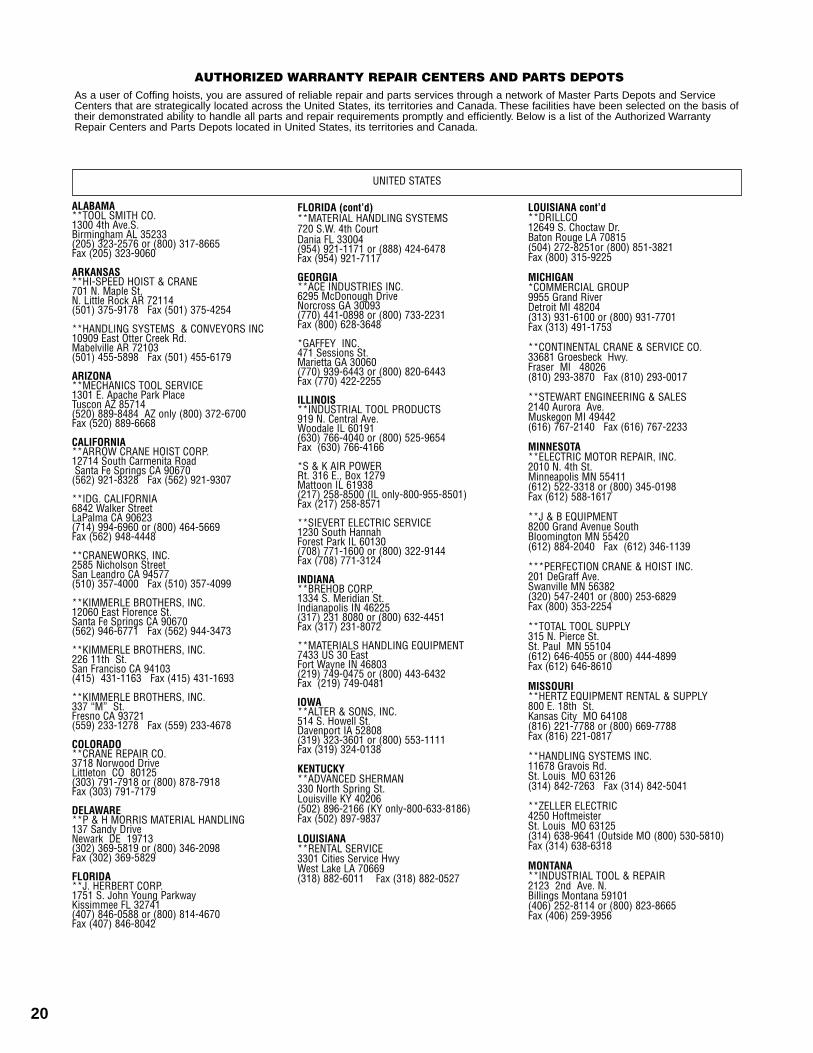
AUTHORIZED WARRANTY REPAIR CENTERS AND PARTS DEPOTS As a user of Coffing hoists, you are assured of reliable repair and parts services through a network of Master Parts Depots and ServiceCenters that are strategically located across the United States, its territories and Canada. These facilities have been selected on the basis oftheir demonstrated ability to handle all parts and repair requirements promptly and efficiently. Below is a list of the Authorized WarrantyRepair Centers and Parts Depots located in United States, its territories and Canada.
UNITED STATES
FLORIDA (cont’d)**MATERIAL HANDLING SYSTEMS 720 S.W. 4th CourtDania FL 33004(954) 921-1171 or (888) 424-6478 Fax (954) 921-7117
GEORGIA**ACE INDUSTRIES INC.6295 McDonough DriveNorcross GA 30093(770) 441-0898 or (800) 733-2231 Fax (800) 628-3648
*GAFFEY INC. 471 Sessions St.Marietta GA 30060 (770) 939-6443 or (800) 820-6443 Fax (770) 422-2255
ILLINOIS**INDUSTRIAL TOOL PRODUCTS919 N. Central Ave.Woodale IL 60191(630) 766-4040 or (800) 525-9654 Fax (630) 766-4166
*S & K AIR POWERRt. 316 E., Box 1279Mattoon IL 61938(217) 258-8500 (IL only-800-955-8501) Fax (217) 258-8571
**SIEVERT ELECTRIC SERVICE 1230 South HannahForest Park IL 60130(708) 771-1600 or (800) 322-9144 Fax (708) 771-3124
INDIANA**BREHOB CORP.1334 S. Meridian St. Indianapolis IN 46225(317) 231 8080 or (800) 632-4451 Fax (317) 231-8072
**MATERIALS HANDLING EQUIPMENT7433 US 30 EastFort Wayne IN 46803 (219) 749-0475 or (800) 443-6432 Fax (219) 749-0481
IOWA**ALTER & SONS, INC. 514 S. Howell St.Davenport IA 52808(319) 323-3601 or (800) 553-1111 Fax (319) 324-0138
KENTUCKY**ADVANCED SHERMAN330 North Spring St. Louisville KY 40206(502) 896-2166 (KY only-800-633-8186) Fax (502) 897-9837
LOUISIANA**RENTAL SERVICE3301 Cities Service HwyWest Lake LA 70669(318) 882-6011 Fax (318) 882-0527
ALABAMA**TOOL SMITH CO.1300 4th Ave.S. Birmingham AL 35233 (205) 323-2576 or (800) 317-8665 Fax (205) 323-9060
ARKANSAS**HI-SPEED HOIST & CRANE 701 N. Maple St, N. Little Rock AR 72114(501) 375-9178 Fax (501) 375-4254
**HANDLING SYSTEMS & CONVEYORS INC 10909 East Otter Creek Rd. Mabelville AR 72103(501) 455-5898 Fax (501) 455-6179
ARIZONA**MECHANICS TOOL SERVICE 1301 E. Apache Park Place Tuscon AZ 85714(520) 889-8484 AZ only (800) 372-6700 Fax (520) 889-6668
CALIFORNIA**ARROW CRANE HOIST CORP. 12714 South Carmenita RoadSanta Fe Springs CA 90670
(562) 921-8328 Fax (562) 921-9307
**IDG. CALIFORNIA 6842 Walker StreetLaPalma CA 90623 (714) 994-6960 or (800) 464-5669Fax (562) 948-4448
**CRANEWORKS, INC.2585 Nicholson StreetSan Leandro CA 94577 (510) 357-4000 Fax (510) 357-4099
**KIMMERLE BROTHERS, INC. 12060 East Florence St.Santa Fe Springs CA 90670(562) 946-6771 Fax (562) 944-3473
**KIMMERLE BROTHERS, INC.226 11th St.San Franciso CA 94103(415) 431-1163 Fax (415) 431-1693
**KIMMERLE BROTHERS, INC.337 “M” St.Fresno CA 93721(559) 233-1278 Fax (559) 233-4678
COLORADO**CRANE REPAIR CO.3718 Norwood DriveLittleton CO 80125(303) 791-7918 or (800) 878-7918 Fax (303) 791-7179
DELAWARE**P & H MORRIS MATERIAL HANDLING 137 Sandy Drive Newark DE 19713 (302) 369-5819 or (800) 346-2098 Fax (302) 369-5829
FLORIDA**J. HERBERT CORP. 1751 S. John Young ParkwayKissimmee FL 32741 (407) 846-0588 or (800) 814-4670 Fax (407) 846-8042
LOUISIANA cont’d**DRILLCO12649 S. Choctaw Dr. Baton Rouge LA 70815(504) 272-8251or (800) 851-3821 Fax (800) 315-9225
MICHIGAN*COMMERCIAL GROUP9955 Grand RiverDetroit MI 48204(313) 931-6100 or (800) 931-7701 Fax (313) 491-1753
**CONTINENTAL CRANE & SERVICE CO.33681 Groesbeck Hwy. Fraser Ml 48026 (810) 293-3870 Fax (810) 293-0017
**STEWART ENGINEERING & SALES2140 Aurora Ave.Muskegon MI 49442 (616) 767-2140 Fax (616) 767-2233
MINNESOTA**ELECTRIC MOTOR REPAIR, INC. 2010 N. 4th St.Minneapolis MN 55411(612) 522-3318 or (800) 345-0198 Fax (612) 588-1617
**J & B EQUIPMENT8200 Grand Avenue South Bloomington MN 55420(612) 884-2040 Fax (612) 346-1139
***PERFECTION CRANE & HOIST INC.201 DeGraff Ave.Swanville MN 56382(320) 547-2401 or (800) 253-6829 Fax (800) 353-2254
**TOTAL TOOL SUPPLY 315 N. Pierce St. St. Paul MN 55104(612) 646-4055 or (800) 444-4899 Fax (612) 646-8610
MISSOURI**HERTZ EQUIPMENT RENTAL & SUPPLY800 E. 18th St.Kansas City MO 64108 (816) 221-7788 or (800) 669-7788 Fax (816) 221-0817
**HANDLING SYSTEMS INC.11678 Gravois Rd. St. Louis MO 63126(314) 842-7263 Fax (314) 842-5041
**ZELLER ELECTRIC4250 Hoftmeister St. Louis MO 63125(314) 638-9641 (Outside MO (800) 530-5810) Fax (314) 638-6318
MONTANA**INDUSTRIAL TOOL & REPAIR2123 2nd Ave. N. Billings Montana 59101(406) 252-8114 or (800) 823-8665 Fax (406) 259-3956
21
UNITED STATES
NEW JERSEY**SISSCO 186 Route 206 South Sommerville NJ 08876(908) 359-9767 or (800) 392-0146 Fax (908) 359-9773
NEW YORK**ABC ELECTRIC 24-25 46th Street.Long Island City NY 11103(718) 956-0000 or (N.Y. only-800-562-1919) FAX (718) 956-4455
**BEATON INDUSTRIAL, INC.6083 Trenton Rd.Utica NY 13502 (315) 797-9346 (N.Y. only-800-724-4052) Fax (315) 797-9321
**VOLLAND ELECTRIC EQUIPMENT CO.75 Innsbruck Drive Buffalo NY 14227(716) 656-9900 Fax (716) 656-8899
NORTH CAROLINA**CAROLINA HOIST3310 E. Wendover Avenue Greensboro NC 27405(336) 375-6050 or (800) 326-3655 Fax (336) 375-6053
**SOUTHERN ELECTRIC SERVICE 2225 Freedom Drive Charlotte NC 28266 (704) 372- 4832 or (800) 487-3726 Fax (704) 342-2604
OHIO**CRANE AMERICA - H. W.HOUSE 920 Deneen AvenueMonroe OH 45050( 513) 539-9770 or (800) 331-5326 Fax (513) 539-9577
**AMERICRANE & HOIST CORP.13224 Enterprise AvenueCleveland OH 44135(216) 267-9100 or (800) 652-1932 Fax (216) 267-9131
*SAMSEL SUPPLY CO.1285 Old River Road Cleveland OH 44113(216) 241-0333 or (800) 892-8012 Fax (216) 241-3426
OKLAHOMA**GAFFEY INC. 6951 E.12th StreetTulsa OK 74112(918) 836-6827 or (800) 331-3916 Fax (918) 835-6138
OREGON **GENERAL TOOL & SUPPLY CO.2705 N.W. Nicolai Portland OR 97210(503) 226-3411 or (800) 783-3411 Fax (503) 778-5518
PENNSYLVANIA**GLOBE ELECTRIC CO.200 23rd StreetPittsburgh PA 15215(412) 781-2677 or (800) 850-4440 Fax (412) 781-1812
*KEYSTONE CRANE & HOIST CO. 861 S. Washington Road McMurray PA 15317(724) 746-5080 Fax (724) 746-5082
PENNSYLVANIA (cont’d)**MCDAL CORP. 475 East Church RoadKing of Prussia PA 19406(610) 277-5484 or (800) 626-2325 Fax (610) 277-4690
**REPAIR UNLIMITED 1730 Rockwell Road Abington PA 19001(215) 657-3335 or (800) 369-5891 Fax (215) 784-0343
RHODE ISLAND **MOTORS , HOIST & CONTROLS INC. 179 Railroad Street Woonsocket RI 02895 (401) 767-4568 Fax (401) 767-4567
SOUTH CAROLINA **ENGINEERED SYSTEMS, INC.1121 Duncan-Reidville RoadDuncan SC 29334 (864) 879-7438 or (800) 879-7438 Fax (864) 848-3143
TENNESSEE**HOIST & CRANE CO.2508 Perimeter PlaceNashville TN 37214 (615) 242-3383 Fax (615) 255- 4379
**HI-SPEED ELECTRICAL CO.3013 Thomas StreetMemphis TN 38127(901) 357-6231 Fax (901) 357-6238
TEXAS**ABEL EQUIPMENT CO., INC.3710 Cavalier DriveGarland TX 75042(972) 272-7706 Fax (800) 272-2235
**GAFFEY, INC. 4301 Garland DriveFt. Worth TX 76117 (817) 281-1994 or (800) 284-4233 Fax (817) 581-7831
**GAFFEY, INC.4003 S. County Road 1297
Odessa TX 79765(915) 563-2897 or (800) 733-0006 Fax (915) 563-4703
**GAFFEY, INC. 1436 N. Duck Creek RoadCleveland TX 77327 (281) 443-6690 or (800) 233-8179 Fax (281) 592-6984
**HYDRAULIC EQUIPMENT SER.1021 N. San Jacinto StreetHouston TX 77002 (713) 228-4073 Fax (713) 228-0931
*INDUSTRIAL HOIST SERVICES Rt. 4 - 1100 South BrooksBrazoria TX 77422 (409) 798-7077 or (800) 766-7077 Fax (409) 798-1963
UTAH **ROCKY MOUNTAIN WIRE ROPE & RIG.2421 South 2570 West Salt Lake City UT 84119(801) 972-4972 or (800) 615-3193
Fax (801) 974-0621 *PARTS DEPOT & REPAIR CENTERS
**PARTS DEPOT & WARRANTY REPAIR CENTER
***PARTS DEPOT
VIRGINIA **FOLEY MATERIAL HANDLING CO.11327 Va. Crane Drive Ashland VA 23005 (804) 798-1343 Fax (804) 798-7843
WASHINGTON **B & J INDUSTRIAL SUPPLY5601 1st Avenue S. Seattle WA 98108(206) 762-4430 or (800) 767-4430 Fax (206) 762-5329
WISCONSIN**ALFERI INDUSTRIAL SALES & SERVICE346 Smith Street Neenah WI 54956 (920) 722-6483 Fax (920) 722-6489
*LIFT INC. 6667 W. Mill RoadMilwaukee WI 53218 (414) 353-5353 or (800) 728-5438 Fax (414) 353-4444
*TRESTER HOIST & EQUIPMENT 4465 124th Street Unit CBrookfield WI 53005 (262) 790-0700 or (800) 234-6098 Fax (262) 790-1009
ALBERTA*KRISTIAN ELECTRIC4215-64 Avenue SECalgary Alberta T2C 2C8(403) 292-9111
BRITISH COLUMBIA***AIR BRAKE REPAIR144 W. 5th AvenueVancouver British Columbia V5Y 1H7(604) 879-7754
MANITOBA***B & B DYNAMO575 McTavish StreetWinnipeg Manitobe R2J 2W5(204) 237-6066
ONTARIO**TORONTO ELECTRIC72 Crockford BlvdScarborough Ontario M1R 3C4(416) 755-7716
**PRO-CRANE HOIST REPAIRS INC.2050 Speers Road, Unit 2Oakville Ontario L6L 2X8(905) 825-2586
QUEBEC**LEGER7995 17th AvenueMontreal Quebec H1Z 5R2(514) 376-3050
**UPTOWN LtEE460 Hubert StreetLaval Quebec H7G 2Y9(514) 667-1859
CANADA
Country Club Road • P.O. Box 779Wadesboro, NC 28170 U.S.A
Phone 800-477-5003 • 704-694-2156 Fax 800-374-6853
Alterations or modifications of equipment and use ofnon-factory repair parts can lead to dangerousoperation and injury.
TO AVOID INJURY:• Do not alter or modify equipment• Do not use equipment to lift, support or otherwise
transport people• Do not suspend unattended loads over people
LIFETIME WARRANTYEvery hoist is thoroughly inspected and testedprior to shipment from the factory. Should anyproblems develop, return the complete hoistprepaid to your nearest Coffing® AuthorizedWarranty Repair Station. If inspection reveals thatthe problem is caused by defective workmanshipor material, repairs will be made without chargeand the hoist will be returned, transportationprepaid.
This warranty does not apply where:(1) deterioration is caused by normal wear, abuse,improper or inadequate power supply, eccentric orside loading, overloading, chemical or abrasiveactions, improper maintenance or excessive heat;(2) problems resulted from repairs, modifications
or alterations made by persons other than factoryor Coffing® Authorized Warranty Repair Stationpersonnel; (3) the hoist has been abused ordamaged as a result of an accident; (4) repairparts or accessories other than those supplied by Coffing® are used on the hoist. Equipment andaccessories not of the seller’s manufacture arewarranted only to the extent that they arewarranted by the manufacturer.EXCEPT AS STATED HEREIN, COFFINGHOISTS® MAKES NO OTHERWARRANTIES, EXPRESSED OR IMPLIED,INCLUDING WARRANTIES OFMERCHANTABILITY AND FITNESS FOR APARTICULAR PURPOSE.
© 2000 Coffing Hoists® Printed in USA11/00


![automecanico.comautomecanico.com/auto2043/altima001.pdf · TIMING CHAIN [QR25DE] 13028 Essocuxs . Apply Genuine RTV Silicone Sealant or equivalent. Refer to Gl Section. Lubricate](https://img.pdfslide.us/doc/110x75/5b034dc37f8b9ab9598f21ad/chain-qr25de-13028-essocuxs-apply-genuine-rtv-silicone-sealant-or-equivalent.jpg)